PT Series Operator & Parts Manual - McConnel
PT Series Operator & Parts Manual - McConnel
PT Series Operator & Parts Manual - McConnel
You also want an ePaper? Increase the reach of your titles
YUMPU automatically turns print PDFs into web optimized ePapers that Google loves.
2. REMEDIES AND PROCEDURES2.01. The warranty is not effective unless the Selling Dealer registers the machine, via the <strong>McConnel</strong>web site and confirms the registration to the purchaser by completing the confirmation form inthe operator’s manual.2.02. Any fault must be reported to an authorised <strong>McConnel</strong> dealer as soon as it occurs. Continueduse of a machine, after a fault has occurred, can result in further component failure for which<strong>McConnel</strong> Ltd cannot be held liable.2.03. Repairs should be undertaken within two days of the failure. Claims submitted for repairsundertaken more than 2 weeks after a failure has occurred, or 2 days after the parts weresupplied will be rejected, unless the delay has been authorised by <strong>McConnel</strong> Ltd.2.04. All claims must be submitted, by an authorised <strong>McConnel</strong> Service Dealer, within 30 days of thedate of repair.2.05. Following examination of the claim and parts the manufacture will pay, at their discretion, forany valid claim the cost of any parts and an appropriate labour allowance if applicable.2.06. The submission of a claim is not a guarantee of payment.2.07. Any decision reached by <strong>McConnel</strong> Ltd. is final.3. LIMITATION OF LIABILITY3.01. The manufacturer disclaims any express (except as set forth herein) and implied warrantieswith respect to the goods including, but not limited to, merchantability and fitness for a particularpurpose.3.02. The manufacturer makes no warranty as to the design, capability, capacity or suitability for useof the goods.3.03. Except as provided herein, the manufacturer shall have no liability or responsibility to thepurchaser or any other person or entity with respect to any liability, loss, or damage caused oralleged to be caused directly or indirectly by the goods including, but not limited to, any indirect,special, consequential, or incidental damages resulting from the use or operation of the goodsor any breach of this warranty. Notwithstanding the above limitations and warranties, themanufacturer’s liability hereunder for damages incurred by the purchaser or others shall notexceed the price of the goods.3.04. No action arising out of any claimed breach of this warranty or transactions under this warrantymay be brought more than one (1) year after the cause of the action has occurred.4. MISCELLANEOUS4.01. The manufacturer may waive compliance with any of the terms of this limited warranty, but nowaiver of any terms shall be deemed to be a waiver of any other term.4.02. If any provision of this limited warranty shall violate any applicable law and is held to beunenforceable, then the invalidity of such provision shall not invalidate any other provisionsherein.4.03. Applicable law may provide rights and benefits to the purchaser in addition to those providedherein.
DECLARATION OF CONFORMITYConforming to EU Machinery Directive 2006/42/ECWe,McCONNEL LIMITED, Temeside Works, Ludlow, Shropshire SY8 1JL, UKHereby declare that:The Product; Tractor Mounted Pasture TopperProduct Code; <strong>PT</strong>P6, <strong>PT</strong>P9Serial No. & Date ………………………………… Type …………………………Manufactured in; United KingdomComplies with the required provisions of the Machinery Directive 2006/42/ECThe machinery directive is supported by the following harmonized standards; BS EN ISO 14121-1 (2007) Safety of machinery - Risk assessment, Part 1:Principles Part 2: practical guide and examples of methods. BS EN ISO 12100-1 (2010) Safety of machinery - Part 1: Basic terminology andmethodology Part 2: Technical principles. BS EN 349(1993)+ A1 (2008) Safety of machinery - Minimum distances to avoid theentrapment with human body parts. BS EN 953 (1998) Safety of machinery - Guards General requirements for thedesign and construction of fixed and movable guards. BS EN 982(1996)+ A1 (2008) Safety requirements for fluid power systems and theircomponents. HydraulicsMcCONNEL LIMITED operates an ISO 9001:2008 quality management system,certificate number: FM25970.This system is continually assessed by the;British Standards Institution (BSI), Beech House, Milton Keynes, MK14 6ES, UKBSI is accredited by UK Accreditation Service, accreditation number: UKAS 003.The EC declaration only applies if the machine stated above is used inaccordance with the operating instructions.Signed …………………................ Responsible PersonCHRISTIAN DAVIES on behalf of McCONNEL LIMITEDStatus: General Manager Date: May 2011
ROTARY MOWER INSPECTION AND MAINTENANCEA daily equipment inspection of the tractor and mower should be conducted before theequipment is used. You may use the inspection sheets to assist with these dailyinspections. Any damaged or missing guards should be repaired or replaced beforeoperating the mower. Failure to repair the damaged shield can result in objects beingthrown from the mower and possibly hitting the operator or bystander.Inspect the Mower for Safe Operating ConditionMake sure the driveline guards and shielding are in place and in good repair. Inspect the chain guards, flexible and/or solid defector thrown object shielding toassure that they are in place on the front and rear of the mower deck and in goodrepair. Repair or replace any damaged or missing thrown object shields.Remove all debris and cut material from the deck and around the gearboxes. Ensure the mower cutting height is set high enough to reduce the possibility of themower blades contacting the ground. Actual height will be dependent on the groundconditions. Increase the height when working in rough or undulating conditions. Inspect for broken, chipped, bent, missing, or severely worn blades. Replacedamaged blades before operating the mower. Ensure the blade retaining bolts andfasteners are secure and tight.Lubricate the driveline universal joints and telescoping members daily. Inspect the wheel lug bolt/nuts to assure that they are tight. If mower is equipped with pneumatic tires, make sure they have the required airpressure. Inspect for worn or damaged decals and safety instructions. Replace unreadable,damaged or missing safety decals. Follow the operator’s manual(s) inspection and maintenance instructions forlubricating parts, and keeping thrown object shielding, driveline guards, rotatingparts shields, mower blades and decals in good repair.Inspect the Tractor for Safe Operating Condition: Inspect the controls, lights, SMVs (Slow Moving Vehicle sign), seat belts, andROPS to assure that they are in place and in good working order.Be sure the tires, wheels, lug bolts/nuts are in good condition.Make sure the tractor brakes and steering are in proper operating condition.Follow the operator’s manual(s) inspection and maintenance procedures forkeeping the tractor in good and safe condition before operating.The inspection sheet on the following page should be kept in this book as a record. Asecond sheet is included for you to cut out and photocopy or the inspection sheets can bedown loaded from our web site at;http://www.mcconnel.com/support/aftersales/default.aspx?nav=After Sales
MOUNTED ROTARY MOWER PRE-OPERATION InspectionMower ID ________________Date: _______________ Shift: _______________WARNINGBefore conducting the inspection, make sure the tractor engine is off, the key removed, allrotation has stopped and the tractor is in park with the parking brake engaged. Make surethe mower is resting on the ground or securely blocked up.ItemThe <strong>Operator</strong>’s <strong>Manual</strong> is in the Canister on the mowerAll Warning Decals are in place, clean and legibleThe mower decks are clear of cut grass and debrisChain Guards/Deflectors are in place & in good conditionDriveline/Gearbox shields/guards are in good conditionDriveline clutches are in good condition, not frozenDriveline telescoping members & u-joints are lubricatedDriveline yokes are securely attached to tractor & mowerGearbox mounting bolts are tightBlade carrier retaining nut is tightBlades are not chipped, cracked, bent or worn outBlade bolts are tightSide skirts and skids are in good conditionThere are no holes or cracks in the machine deckWheel nuts are tightAll linkage mounting pins are securely fastenedLift height is restricted to prevent <strong>PT</strong>O hitting the deckCondition atstart of shiftSpecific Comments if not O.K.<strong>Operator</strong>s Signature: ___________________________________________DO NOT OPERATE an UNSAFE TRACTOR or MOWER
TRACTOR PRE-OPERATION InspectionPower Arm ID ________________ Date: _______________ Shift: _______________WARNING Before conducting the inspection, make sure the tractor engine is off, the key is removedall rotation has stopped and the tractor is in park with the parking brake engaged. Anyimplement attached to the tractor is firmly on the ground.ItemThe flashing lights function properly.All lights are clean and working correctlyAll cab windows are clean and wipers working correctlyThe SMV sign, where required, is clean and visible.The tyres are in good condition with correct pressure.The wheel nuts are tight.The tractor brakes are in good condition.The steering linkage is in good condition.There are no visible oil leaks.The hydraulic controls function properly.The ROPS or ROPS cab is in good condition.The seatbelt is in place and in good condition.The 3-point hitch is in good condition.The drawbar/pick up hook is secure & in good conditionThe <strong>PT</strong>O master shield is in place.The engine oil level is full.The brake fluid level is full.The power steering fluid level is full.The fuel level is adequate.The engine coolant fluid level is full.The radiator & oil cooler are free of debris.The air filter is in good conditionCondition atstart of shiftSpecific Comments if not O.K.<strong>Operator</strong>s Signature: ___________________________________________DO NOT OPERATE an UNSAFE TRACTOR or MOWER
McCONNEL LIMITEDTemeside WorksLudlowShropshire SY8 1JLEnglandTelephone: 01584 873131www.mcconnel.com
LIST OF CONTENTSPage No.Operation SectionIntroduction 1Features 3Specifications 4Safety Information 5Safety Decals 9Safety Decal Locations 10Tractor Requirements 11Unpacking the Machine 12Tractor Preparation 15Attaching the Machine 16<strong>PT</strong>O Driveshaft Installation 22Machine Disconnection & Storage 23Transporting the Machine 24Moving from Transport to Work Position 26‘Running Up’ the Machine 27Machine Operation 28Shear Bolt Protection 31Cleaning the Machine 32Maintenance 33Recommended Lubricants 42Torques Settings 42Troubleshooting Guide 43<strong>Parts</strong> SectionDeck Assembly – <strong>PT</strong>180 46Hitch Frame & Arm Assembly – <strong>PT</strong>240 48Deck & Drive Covers Assembly – <strong>PT</strong>240 49Deck Assembly – <strong>PT</strong>270 50Drive Cover Assembly – <strong>PT</strong>270 51Skids Assembly – <strong>PT</strong>180 52Skids Assembly – <strong>PT</strong>240/270 53Drive Assembly – <strong>PT</strong>180 54<strong>PT</strong>O Driveshaft – <strong>PT</strong>180 55<strong>PT</strong>O & Drive Assembly – <strong>PT</strong>240 56Drive Assembly – <strong>PT</strong>270 57<strong>PT</strong>O Driveshaft – <strong>PT</strong>270 58Rotor & Blades – <strong>PT</strong>180 59Rotors & Blades – <strong>PT</strong>240 60Rotors & Blades – <strong>PT</strong>270 61Basic Decal Kit – <strong>PT</strong>180 62Basic Decal Kit – <strong>PT</strong>240/270 63Specific Decal Kit – <strong>PT</strong>180 64Specific Decal Kit – <strong>PT</strong>240 65Specific Decal Kit – <strong>PT</strong>270 66Stacking Legs – <strong>PT</strong>180/240/270 67
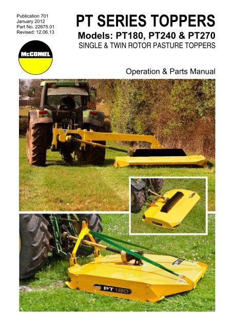
INTRODUCTION<strong>McConnel</strong> <strong>PT</strong>180, <strong>PT</strong>240 & <strong>PT</strong>270 machines are tractor mounted rotary mowers primarilydesigned for the topping of grass pasture land after grazing, or for weed and thistle controlon agricultural land. The machines are not designed for grass mowing, or for the cutting ofset-aside, or brush/woodland clearance.<strong>PT</strong>180 and <strong>PT</strong>270 models are ‘inline machines for working directly behind the tractor withcutting widths of 1.8m and 2.75m respectively. On <strong>PT</strong>180 models the deck can be mountedto its attachment frame in a choice of 3 positions to allow semi-offset working.The <strong>PT</strong>240 model is a fully offset machine for working directly to the side of the tractor andfeatures a cutting width of 2.4m.<strong>PT</strong>180 machines are equipped with a single rotor and <strong>PT</strong>240 and <strong>PT</strong>270 are equipped withtwin rotors that rotate in opposite directions.Model & Components Identification<strong>PT</strong>180 Model ►A) Machine Body/DeckB) GearboxC) SkidD) HeadstockE) <strong>PT</strong>O ShaftF) Transport Straps<strong>PT</strong>270 Model ►A) Machine Body/DeckB) Top Cover*C) SkidD) Lift Arm BracketsE) <strong>PT</strong>O Shaft* Gearboxes & Driveshaftsbeneath this cover1
<strong>PT</strong>240 ModelA) Machine Body/DeckB) GearboxC) SkidD) BeamE) Top Covers (Shown removed to display drive components)F) <strong>PT</strong>O ShaftG) Driveshafts & CouplingsH) Headstock / Linkage FrameI ) Transport LatchJ) RamBlade Unit Components ►A) Rotor HubB) Blade CarrierC) Blades<strong>PT</strong>270 model shown2
FEATURES<strong>PT</strong>180 Modelo Working width of 1.80mo Three position bolt on headstocko Inline or semi-offset cutting positionso Deep cranked free swinging bladeso 540-RPM <strong>PT</strong>O Shaft driveo Shear bolt protectiono Over-run protection on <strong>PT</strong>Oo Single rotoro Side skidso Easily adjustable cutting heighto Lower link floatation<strong>PT</strong>240 Modelo Working width of 2.40mo Three-point Linkage Mountedo Fully offset cutting positiono Hydraulic breakback safety systemo Deep cranked free swinging bladeso 540-RPM <strong>PT</strong>O Shaft driveo Shear bolt protectiono Over-run protection on <strong>PT</strong>Oo Twin rotoro Side skidso Easily adjustable cutting heighto Floatation system<strong>PT</strong>270 Modelo Working width of 2.75mo Easy hitch lift arm bracketso Inline cutting positionso Deep cranked free swinging bladeso 540-RPM <strong>PT</strong>O Shaft driveo Shear bolt protectiono Over-run protection on <strong>PT</strong>Oo Twin rotoro Side skidso Easily adjustable cutting heighto Lower link floatation3
SPECIFICATIONSDescription <strong>PT</strong>180 Model <strong>PT</strong>240 Model <strong>PT</strong>270 ModelMaximum Cutting Width 1.8m (5’11”) 2.4m (7’11”) 2.75m (9’)Minimum Power Requirement 30HP (22kW) 45HP (33kW) 45HP (33kW)Machine Weight 500kg 565kg 565kgAttachment Type 3-point Linkage 3-point Linkage 3-point LinkageCutting Height 24 – 114mm 24 – 114mm 24 – 114mmCutting Capacity (Max. Diameter) 30mm 30mm 30mmOverall Machine Width 2.0m (6’7”) 2.6m (8’6”) 2.94m (9’8”)<strong>PT</strong>O Speed 540RPM 540RPM 540RPMProtection Shear Bolt Shear Bolt Shear BoltOffset Capability Yes (Semi) Yes (Fully) NoNumber of Rotors 1 2 2Number of Blade Carriers 1 2 2Number of Blades 2 4 4Blade Tip Speed 4500m/min 4620m/min 4620m/minBlade Overlap N/A 50mm 50mmNumber of Skids 2 2 2Note: All weights, dimensions and power requirements are approximate and are for guidance purposes only.4
SAFETYThere are obvious and potential hazards in the operation of this mower. The blades of thismower can propel objects for a great distance at very high speeds. Serious injury or evendeath may occur unless care is taken to ensure the safety of the operator, bystanders orpassersby in the area.KEEP CLEARBefore attempting to operate this machine the owner and the operator should read,understand and heed the following information. Serious injury or death may occur if thesafety advice given here is ignored. In addition to this safety advice, good ‘common sense’will go a long way towards avoiding hazardous situations and reduce the risk of danger.Rotary mowers are capable under adverse conditions of throwing objects greatdistances (100 yards or more) and causing serious injury or death.STOP MOWING IF PASSERSBY ARE WITHIN 100 YARDS (91 metres)unless: Front and rear deflectors, chain guards or bands are fitted and are in goodworkable condition. Mower sections or wings are running close to, and parallel to, the groundwithout exposed blades. Passersby are outside the existing thrown-object zone. All areas have been thoroughly inspected and foreign materials such asrocks, cans, glass and general ‘risk’ debris have been removed.NOTE: Where grass and weeds are high enough to obscure debris that could be struck bythe blades, the area should be inspected and debris removed, mowed at an intermediateheight, and re-inspected closely to remove any remaining debris and mowed again at thedesired final height. (In addition to the safety aspect of this procedure it will also reduce wearand tear on the mower drive-train, spread cut materials better, eliminate ‘streaking’ andmake the final cut more uniform).All guards, bands, deflectors, driveline shields and gearbox shields should beused and maintained in good working condition at all times. They should becarefully inspected daily for missing or broken cable, chain links, shields orguards. Missing, broken or worn items must be replaced before attempting touse the machine to reduce the possibility of injury from thrown objects orentanglement.Extreme care should be taken when operating near loose objects such asgravel, rocks, wire and other debris. Foreign objects should be removed fromthe work site or avoided to prevent machine damage and/or bodily injury oreven death.The rotating parts of this machine have been designed and tested for ruggeduse. However, they could fail upon impact with heavy solid objects such assteel guardrails and concrete abutments. Such impact could cause the brokenobjects to be thrown outward at very high velocities. To reduce the possibility ofproperty damage, serious injuries, or even death, never allow the cuttingblades to contact such objects.5
The operator and all support personnel should wear ‘hard hats’, ‘safety shoes’and ‘safety glasses’ at all times for protection from injury by falling objects anditems thrown by the machine.Operate the mower only with a tractor equipped with an approved ‘roll overprotection system (ROPS). Always wear your seat belt. Serious injury or evendeath could result from falling off the tractor – particularly during a turnoverwhen the operator could be pinned under the ROPS or the tractor.Before leaving the tractor seat always engage the brake and/or set the tractortransmission in parking gear. Disengage the <strong>PT</strong>O, stop the engine, remove thekey and wait for all moving parts to stop. Place the tractor shift lever into a lowrange or parking gear to prevent the tractor from rolling. Never mount ordismount a moving tractor. Operate the tractor controls from the tractor seatonly.Many varied objects such as wire, cable, rope or chains can become entangledin the operating parts of mower head. These items could then swing outsidethe housing at greater velocities than the blades. Such a situation is extremelyhazardous. Inspect the cutting area for any such objects and remove prior tomowing. Never allow the cutting blades to contact such items.Be particularly careful in transport. Turn curves or go up hills only at a lowspeed and at a gradual steering angle. Ensure that at least 20% of the tractor’sweight is on the front wheels to maintain safe steering. Slow down on rough oruneven surfaces.Ensure that all necessary signs are correctly displayed, and clearly visible,when working or transporting on or near a public highway. (Contact your LocalHighway Authority to ensure you are fully conversant with your responsibilitieson this subject). Use flashing warning lights when working or transporting on ornear a public highway to indicate to other road users a potential hazard.Always abide by local traffic regulations.Ensure all moving parts of the machine are regularly inspected for wear andreplaced with authorised service parts if an excessive amount of wear ispresent.Always use shear bolts recommended by <strong>McConnel</strong>.Ensure the machine is regularly inspected for loose fasteners, worn or brokenparts and loose or leaky fittings. Ensure all pins are fitted with cotter pins andwashers. Serious injury can result from failure to maintain this machine in goodworking order.6
Never leave the machine in the raised transport position – the machine couldfall inadvertently and cause injury or death to anyone who might be under themachine.Never clean or adjust <strong>PT</strong>O driven equipment with the tractor engine running.Kill the engine and pocket the key before attempting any maintenance on themachine.Never allow riders on either the tractor or the mower - falling off can kill.Never allow children to operate, ride on, or come close to the mower or thetractor.Never work under the mower deck, framework or any raised component unlessthe mower has been securely supported and blocked using suitable substantialitems to prevent sudden or inadvertent falling which could cause serious injuryor even death.Never operate the tractor and mower until you have read, and fully understood,the operation manual and are conversant with all the safety instructions statedhere. Ensure you read all safety messages found on both the tractor and themower.Ensure you maintain all safety decals in good readable condition. If a decalshould for any reason become illegible order a replacement immediately beforepermitting the machine to be used.Never run a tractor engine in a closed building without adequate ventilation.The exhaust fumes can be hazardous to your health.7
Ensure that a <strong>PT</strong>O shield is installed when using <strong>PT</strong>O-driven equipment andalways replace the <strong>PT</strong>O shield if damaged.PROLONGED EXPOSURE TO LOUD NOISE MAY CAUSE PERMANENTHEARING LOSS! Tractors with or without mowers attached can often be noisyenough to cause permanent or partial hearing loss. We recommend thathearing protection be worn at all times when the noise level experienced in theoperator’s position exceeds 80db. Noise in excess of 85db on a long-termbasis can cause permanent total hearing loss. Where the tractor is fitted with a‘quiet cab’ it is recommended that the windows are kept closed at all timeswhilst operating this machine.In addition to the safety messages stated here the machine is fitted with warning decals thatare designed to bring to the attention of the operator the potential dangers that exist whilstusing the machine. However, these cannot replace correct proper training and totalawareness of all the dangers involved in using a machine of this type, and the nature of thework it does. BE ALERT, PAY ATTENTION – SOMEONE’S LIFE MAY BE AT STAKE!WHEN THIS SYMBOL IS DISPLAYED:BE ALERTPAY ATTENTIONSOMEONE’S LIFE IS AT STAKE8
SAFETY & INSTRUCTIONAL DECALS IDENTIFICATIONRead and Comply with <strong>Operator</strong>’s <strong>Manual</strong>Read and understand the <strong>Operator</strong>’s <strong>Manual</strong> before attaching andoperating this machine.Stop the Tractor before Working on the MachineAlways let the tractor come to a stop, and remove the starter keybefore you adjust, lubricate, repair or carry out any maintenance workon the machine.Keep a Safe Distance from the MachineDanger of flying objects when machine is working. Bystanders mustkeep a safe distance when the machine is being used.Beware of Rotating Blades.Danger of cutting or severing of limbs under covered rotating parts. Donot reach or probe under the machine when it is driven by the tractor.Machine Lifting PointsWhen lifting the machine with other than approved tractor attachmentpoints, use the marked lifting points for safe and balanced lifting.Input <strong>PT</strong>O SpeedThe rated <strong>PT</strong>O speed for this machine is 540 rpm. For optimumperformance, the machine should be driven at this speed. Under nocircumstances should this speed be exceeded.Risk of Hand EntanglementRotating parts under cover.9
LOCATION OF SAFETY & INSTRUCTIONAL DECALS<strong>PT</strong>180 Model<strong>PT</strong>240 & <strong>PT</strong>270 Models<strong>PT</strong>270 illustratedNOTE: On <strong>PT</strong>240 models the lifting points are located on each corner of the machine and not as illustrated above.10
TRACTOR REQUIREMENTSWARNING: The tractor must have adequate weight and capacity to lift and carry themachine. Local legislation governing this ratio must be observed. The correct ratio betweentractor and machine ensures correct braking functions and manoeuvrability. An incorrectratio between tractor and machine can be dangerous.<strong>PT</strong>180 Model ►<strong>PT</strong>180 machines are connected to thetractor on the 3 point hitch, and willaccept either CAT 1 or CAT 2 linkages.The tractor must also be equipped with alevelling box. If the tractor is fitted with aswinging drawbar, this should be set inits shortest mode or removedcompletely. The tractor should beequipped with a six-splined <strong>PT</strong>O andrevolve at 540 rpm.<strong>PT</strong>180<strong>PT</strong>240 Model ►<strong>PT</strong>240 machines are connected to thetractor on the 3 point hitch, and willaccept only CAT 2 linkages. The tractormust also be equipped with a levellingbox. If the tractor is fitted with a swingingdrawbar, this should be set in its shortestmode or removed completely. Thetractor should be equipped with a sixsplined<strong>PT</strong>O and revolve at 540 rpm.<strong>PT</strong>240<strong>PT</strong>270 Model ►<strong>PT</strong>270 machines are connected to thetractor on the 2 point hitch, and willaccept only CAT 2 linkages. The tractormust also be equipped with a levellingbox. If the tractor is fitted with a swingingdrawbar, this should be set in its shortestmode or removed completely.The tractor should be equipped with asix-splined <strong>PT</strong>O and revolve at 540 rpm.<strong>PT</strong>27011
UNPACKING THE MACHINE – <strong>PT</strong>180 ModelsWARNING: Only use approved lifting equipment which is correctly fastened to the machine -this will increase your personal safety. Failure to follow the safety instructions could resultin accidents and serious injuries.Using a ForkliftGuides are provided on the machine to enable movement by forklift. It is essential that theblade carrier and blades are positioned parallel with the fork lift tines. The tines should befully inserted, angled downwards slightly, with the tips engaging underneath the crossmember.CAUTION: Failure to position the blade carrier and blades correctly can result in damage to the machine.Location of forklift lifting points.Remove <strong>PT</strong>O shaft from storage position.Remove stacking / transport legs (if fitted).Remove blade restrainer wires / cable ties.On despatch from the factory the rotors and blades of the machine will be secured withrestraining wires and/or cable ties to stop them moving during delivery; these restrainingwires must be removed before using the machine.WARNING: Before attempting to access the underside of the machine, ensure it isadequately and safely supported. Do not rely on the tractor’s hydraulics. Use safetysupports that have a minimum Safe Working Load (SWL) of 1.5 tonnes.With the machine suitably supported, remove all rotor and blade restraining wires and/or ties.Inspect the underside of the machine to ensure it is undamaged, and check all blades rotatefreely and do not foul on the body.12
UNPACKING THE MACHINE – <strong>PT</strong>240 ModelsWARNING: Only use approved lifting equipment which is correctly fastened to the machine -this will increase your personal safety. Failure to follow the safety instructions could resultin accidents and serious injuries.Handling the MachineThe machine should be lifted using suitable overhead lifting gear specifically designed forhandling loads of this nature. Ensure lifting equipment has a SWL of 1.5 tonnes minimum.The machine must only be lifted using all four approved lifting points, the locations of whichare indicated in the illustration above.Ensure the machine is evenly balanced before attempting to raise the machine and keep allbystanders at a safe distance from the raised load.Remove the <strong>PT</strong>O shaft from its storage position and place it safely away from the machine.Remove stacking / transport legs (if fitted).Remove blade restrainer wires / cable ties.On despatch from the factory the rotors and blades of the machine will be secured withrestraining wires and/or cable ties to stop them moving during delivery; these restrainingwires must be removed before using the machine.WARNING: Before attempting to access the underside of the machine, ensure it isadequately and safely supported. Do not rely on the tractor’s hydraulics. Use safetysupports that have a minimum Safe Working Load (SWL) of 1.5 tonnes.With the machine suitably supported, remove all rotor and blade restraining wires and/or ties.Inspect the underside of the machine to ensure it is undamaged, and check all blades rotatefreely and do not foul on the body.13
UNPACKING THE MACHINE – <strong>PT</strong>270 ModelsWARNING: Only use approved lifting equipment which is correctly fastened to the machine -this will increase your personal safety. Failure to follow the safety instructions could resultin accidents and serious injuries.Using a ForkliftAccess to two fork guides are providedthrough the lift arm channels at the front ofthe machine. This enables movement ofthe complete unit by forklift.Forklift lifting points – through lift arm channels.Remove <strong>PT</strong>O shaft from its storage position.Remove stacking / transport legs (if fitted).Remove blade restrainer wires / cable ties.On despatch from the factory the rotors and blades of the machine will be secured withrestraining wires and/or cable ties to stop them moving during delivery; these restrainingwires must be removed before using the machine.WARNING: Before attempting to access the underside of the machine, ensure it isadequately and safely supported. Do not rely on the tractor’s hydraulics. Use safetysupports that have a minimum Safe Working Load (SWL) of 1.5 tonnes.With the machine suitably supported, remove all rotor and blade restraining wires and/or ties.Inspect the underside of the machine to ensure it is undamaged, and check all blades rotatefreely and do not foul on the body.14
TRACTOR PREPARATIONWARNING: Ensure that all operators have read and thoroughly understood all the safetyprocedures. For further information refer to the relevant sections of this manual.WARNING: When connecting the machine to a tractor there is a risk of personal injury.Failure to follow the safety instructions could result in serious injuries to either yourself orothers. Therefore, when connecting the machine and the tractor you should: Make sure the tractor cannot roll. Make sure that the tractor and the machine have compatible category attachments. Never stand between the tractor and the machine during attachment. Use the hydraulic three point linkage slowly and carefully. When carrying out an attachment you must make sure that the machine is placed on a firm andlevel surface.Remove tractor drawbar or position it to one side so it does not foul on the <strong>PT</strong>O shaft15
ATTACHING THE MACHINE – <strong>PT</strong>180 ModelsAttachment of the machine should be performed on a firm level site - the procedure forattachment is as follows;Support the ‘A’ frame and remove the 3 link pinsbefore reversing the tractor up to the machine -adjust lift arm height to align with the pin holes onthe machine.Turn off the tractor, apply parking brake andremove the starting key. Attach lower lift armsand ‘A’ frame to the machine using the Cat I/IIpins supplied.Raise ‘A’ frame into the position shown and fit thetop link. Adjust the length of the link to removeany slack and to tension the transport strap,without lifting the rear of the machine off theground.Start the tractor and raise the machine on the liftarms until the gearbox <strong>PT</strong>O shaft of the machineand the tractor <strong>PT</strong>O are at their shortest distanceapart. Turn off the tractor, apply parking brakeand remove the starter key.16
Adjust the tractor stabiliser chains/bars to removeany lateral movement when the machine is in theraised position.Connect the end of the <strong>PT</strong>O shaft that has theshear bolt to the machine’s gearbox. Secure the<strong>PT</strong>O guard retraining chain to a suitable locationon the machine.Connect the other end of the <strong>PT</strong>O shaft to thetractor’s <strong>PT</strong>O drive. Secure the <strong>PT</strong>O guardretraining chain to a suitable location on thetractor.NOTE: On initial installation the <strong>PT</strong>O shaft lengthmay need adjusting to suit this particularapplication; refer to <strong>PT</strong>O driveshaft installationpage for details of this procedure.With the <strong>PT</strong>O shaft correctly connected, raise themachine to a safe transport position. Ensure aclearance of at least 100mm between theunderside of the shaft and the body of themachine whilst in the transport position. Lock the‘lift arm stop’ in this position.Check that there is no lateral movement on themachine when it is in the raised position; adjustthe stabiliser chains/bars if required.CAUTION: Raising the tractor lift arms too high may cause damage to the <strong>PT</strong>O shaft if thetractor was to drive over any bumps and the machine was to bounce on the lift arms.WARNING: Read all the safety instructions carefully before driving on the public road andalways comply with the local law concerning lights, warning and safety signs. The driverand/or the owner of the machine have the responsibility of complying with the local RoadTraffic Acts.Always ensure tractor manoeuvrability is not adversely affected by any attached machinery; the steeringaxle of the tractor should be loaded with at least 20% of the tractor’s dead weight.Carrying of passengers on the machine is strictly prohibited.17
ATTACHING THE MACHINE – <strong>PT</strong>240 ModelsAttachment of the machine should be performed on a firm level site - the procedure forattachment is as follows;Remove the top link pin (1) and the two Cat IIpins (2 & 3).Reverse tractor slowly up to the machine - adjustthe lift arm height to align with the pin holes. Turnoff the tractor, apply the parking brake andremove the starter key. Attach lower link arms tothe machine using the Cat II pins supplied andsecure with lock pins.NOTE: Adjust and attach the Left Hand Lift Arm by using the tractor Levelling Box if necessary.Attach the tractor top link to the single hole in thetop of the headstock using the top link pinprovided and secure with lock pin.Start the tractor and raise the machine on the liftarms until the gearbox <strong>PT</strong>O shaft of the machineand the tractor <strong>PT</strong>O are at their shortest distanceapart. Turn off the tractor, apply parking brakeand remove the starter key.Adjust the tractor stabiliser chains/bars toremove any lateral movement when the machineis in the raised position.18
Remove parking leg pin and raise the leg clear ofthe ground – replace pin and secure with lock pin.Connect the end of the <strong>PT</strong>O shaft that has theshear bolt to the machine. Secure the <strong>PT</strong>O guardretraining chain to a suitable location on themachine.Connect the other end of the <strong>PT</strong>O shaft to thetractor’s <strong>PT</strong>O drive. Secure the <strong>PT</strong>O guardretraining chain to a suitable location on thetractor.NOTE: On initial installation the <strong>PT</strong>O shaft lengthmay need adjusting to suit this particularapplication; refer to <strong>PT</strong>O driveshaft installationpage for details of this procedure.Connect the hydraulic hose fittings to the tractorspool valve.Unpack the Transport Latch Pull Cord and routeit into the tractor cab through the rear window – itshould be located in a position that is within easyreach of the operator from the tractor seat.Ensure the routing of the cord is such that it allowssufficient slack to avoid accidental or unintentionaloperation, and that it remains clear of all movingcomponents on both the tractor and the machineat all times.19
ATTACHING THE MACHINE – <strong>PT</strong>270 ModelsAttachment of the machine should be performed on a firm level site - the procedure forattachment is as follows;Remove the two Cat II link pins and reverse thetractor up to the machine - adjust the height ofthe lift arms so they align with the pin holes onthe machine.Carefully reverse the tractor fully in to locate thelift arms within the receiving channels of themachine and attach in position using the Cat IIpins supplied. The machine has 3 pin positions –select the one that gives approximately 50mmclearance between lower lift arm and machine.NOTE: An insufficient amount of clearance will prevent the machine from ‘floating’ correctly.Start the tractor and raise the machine on the lift arms until the gearbox <strong>PT</strong>O shaft of the machineand the tractor’s <strong>PT</strong>O drive are at their shortest distance apart. Turn off the tractor, apply the parkingbrake and remove the starter key.Adjust the tractor stabiliser chains/bars so thereis no lateral movement when the machine is inthe raised position.Connect the end of the <strong>PT</strong>O shaft that has theshear bolt to the machine’s gearbox. Secure the<strong>PT</strong>O guard retraining chain to a suitable locationon the machine.20
Connect the other end of the <strong>PT</strong>O shaft to thetractor’s <strong>PT</strong>O drive. Secure the <strong>PT</strong>O guardretraining chain to a suitable location on thetractor.NOTE: On initial installation the <strong>PT</strong>O shaftlength may need adjusting to suit this particularapplication; refer to <strong>PT</strong>O driveshaft installationpage for details of this procedure.With the <strong>PT</strong>O shaft correctly connected, raisethe machine to a safe transport position. Ensurea clearance of at least 100mm between theunderside of the shaft and the body of themachine whilst in the transport position. Lockthe ‘lift arm stop’ in this position.Check that there is no lateral movement on themachine when it is in the raised position; adjustthe stabiliser chains/bars if required.CAUTION: Raising the tractor lift arms too high may cause damage to the <strong>PT</strong>O shaft if thetractor was to drive over any bumps and the machine was to bounce on the lift arms.WARNING: Read all the safety instructions carefully before driving on the public road andalways comply with the local law concerning lights, warning and safety signs. The driverand/or the owner of the machine have the responsibility of complying with the local RoadTraffic Acts.Always ensure tractor manoeuvrability is not adversely affected by any attached machinery; the steeringaxle of the tractor should be loaded with at least 20% of the tractor’s dead weight.Carrying of passengers on the machine is strictly prohibited.21
<strong>PT</strong>O DRIVESHAFT INSTALLATIONThe <strong>PT</strong>O driveshaft attaches between the tractor and the machine gearbox to transfer thepower required to the run and operate the machine – it is important to achieve the correctshaft length to avoid risk of it ‘bottoming out’ when raising or lowering the machine.The procedure for measuring and cutting the shaft is as follows;Measuring the <strong>PT</strong>O ShaftWith the machine attached to the tractorin the working position measure thehorizontal distance ‘A’ from the tractor’s<strong>PT</strong>O to the input shaft on the machinesgearbox and subtract 75mm (3”) – thisfigure is the required shaft length.Place the fully closed <strong>PT</strong>O shaft on theground and measure its overall length, ifthe shaft is shorter than the requiredlength you can use it without the needto shorten - providing it allows for aminimum 150mm (6”) overlap whenfitted.If the shaft is longer subtract therequired shaft length plus an additional75mm (3”) - the resulting figure is theexcess length that will need to beremoved from each half of the shaft.Cutting the <strong>PT</strong>O ShaftSeparate the two halves and using themeasurement obtained above shortenboth the plastic guarding and the innersteel profile tubes of each shaft by thissame amount. De-burr the cut tubeswith a file to remove rough or sharpedges and thoroughly clean to removeswarf before greasing, assembling andfitting the shaft.NOTE: For subsequent use with different tractors the shaft should be measured again tocheck suitability – there must be a minimum shaft overlap of 150mm (6”).<strong>PT</strong>O MaintenanceTo increase the working life of the <strong>PT</strong>O shaft it should be periodically checked, cleaned andlubricated – refer to the manufacturer’s manual provided with the shaft for further details onthis subject.22
MACHINE DISCONNECTION & STORAGEDisconnecting the MachineDisconnection of the machine is a reversal of the attachment procedure – refer to theattachment sections for details.WARNING:There is an increased risk of injury when disconnecting the machine from the tractor.Before attempting to disconnect the machine, make sure that: The machine is placed on a firm and level surface. The tractor cannot roll after being disconnected. The tractor has stopped, the parking brake is applied and the starter key is removed. The machine has come to a complete stop before commencing work. Bystanders are kept at a safe distance from the machine and tractor. Before leaving the machine ensure it is left in a safe condition. Do not allow children to play on or near the machine, even when it is disconnected; there aremoveable components on the machine that can risk injury.Machine StorageAt the end of the season the machine should be readied for winter storage. The storagelocation is ideally in a dry well ventilated building that will offer the machine protection fromthe elements. Before placing the machine into storage the following tasks should beperformed; Clean the machine thoroughly. Check that the machine's safety equipment is not worn or damaged - replace if required. Clean and lubricate the <strong>PT</strong>O shaft and store it in a safe dry environment to avoid risk ofdamage or corrosion. Repair or replace any damaged components. Replace any defective components. Check and tighten all bolts. Lubricate the machine following the lubrication program. Repair any paint damage and replace any missing decals.When storing or parking the machine always ensure it is left in a safe condition without riskof harm or injury to persons or animals, if necessary use suitable props or blocks to supportthe machine.23
TRANSPORTING THE MACHINEFor transportation between work sites the machine should be raised to a suitable carryingheight and the tractors ‘lift arms stops’ locked at that position; on <strong>PT</strong>180 & <strong>PT</strong>270 modelsensure a minimum clearance distance of 100mm is retained between the underside of the<strong>PT</strong>O shaft and the body of the machine - see photos below.<strong>PT</strong>180 – <strong>PT</strong>O shaft clearance required for transport<strong>PT</strong>270 – <strong>PT</strong>O shaft clearance required for transportCAUTION: Raising the tractor lift arms too high may cause damage to the <strong>PT</strong>O shaft if thetractor was to drive over any bumps and the machine was to bounce on the lift arms.<strong>PT</strong>240 – Transport PositionWARNING: Read all the safety instructions carefully before driving on the public road andalways comply with the local law concerning lights, warning and safety signs. The driverand/or the owner of the machine have the responsibility of complying with the local RoadTraffic Acts.Always ensure tractor manoeuvrability is not adversely affected by any attached machinery; the steeringaxle of the tractor should be loaded with at least 20% of the tractor’s dead weight.Carrying of passengers on the machine is strictly prohibited.Before Driving on Public RoadsThe machine should be raised on the lift arms to the transport position and the followingchecks made: Is the machine correctly coupled with all securing pins and clips in position? Does the machine have any loose or unsecured parts? Are the tractor’s lights, indicators and beacon working correctly and are they all clearlyvisible? Are there any bystanders or children in the immediate area? If so, ask them to clear thearea before moving off.24
Driving on Public Roads Check the area around the machine before you start. Be aware of children in the dangerarea of the machine. Do not exceed 30 km/h. Adjust the speed according to the road conditions. Avoid sudden sideways movement with the machine attached. Make sure that steering and braking ability are not compromised. Take care when turning corners as the machine may swing out into the path of other roadusers.25
MOVING FROM TRANSPORT TO WORK POSITION – <strong>PT</strong>240 ModelsEnsure that the machine and the <strong>PT</strong>O shaft have been correctly connected to the tractor. Forfurther information refer to the ‘Machine Attachment’ section.Ensure that the immediate surroundings will not cause a restriction to the moving andchecking of the machine.Ensure there are no children, bystanders or animals within the immediate area of themachine.With the machine raised clear of the ground byapproximately 100mm pull the transport latchrelease cord and carefully operate the hydraulicspool valve to retract the hydraulic ram, this willpull the swing arm through 90° and place thedeck of the machine in the work position on theright hand side of the tractor.Lower the machine so the skids are resting onthe ground, apply handbrake and turn off thetractor engine.Remove the top link pin from the single hole onthe headstock and reposition the top link withthe pin in the slotted hole directly below; this willallow better floatation when operating themachine.NOTE: To operate the machine with the hydraulic safety breakback feature, the hydraulic spool levershould be in “float” position. This gives free flow of oil return to the tractor should an obstacle beencountered.WARNING: Failure to operate without free float return to the tractor may result in seriousdamage to your machine.The procedure for moving the machine from working position to transport position is the reverse ofthe above procedure. The Transport Latch will automatically lock the swing arm in position when theram is fully extended.WARNING: At no time should the machine be moved from working to transport positionwhilst the <strong>PT</strong>O is engaged, or the machine is running down. Ensure the rotors are at acomplete standstill before moving swing arm. Failure to observe this guidance is likely tocause serious driveline damage.26
‘RUNNING UP’ THE MACHINEBefore UseWARNING:Ensure that all operators have read and thoroughly understood all the safetyprocedures. For further information refer to the relevant sections of this manual.Running the Machine for the First TimeEnsure that the machine and the <strong>PT</strong>O shaft have been correctly connected to thetractor as stated in the ‘machine attachment sections’ of this manual.Select a safe open area in which to ‘run-up’ and check the machine. Ensure thereare no children, bystanders or animals in the immediate area when the machine isrun for the first time.After the machine has been attached to the tractor for the first time, it should be tested toensure it operates correctly before putting it to work. Use the following procedure whenrunning the machine for the first time.1. Lower the machine so the skids are resting on the ground and the machine is level.2. With the tractor at low revs, gently engage the <strong>PT</strong>O until the machine is running.3. Carefully increase the <strong>PT</strong>O speed to 540 rpm.4. Check that the machine runs smoothly and without vibration.5. Raise the machine to the transport position.6. Check again that the machine runs smoothly and without vibration.7. Lower the machine to ground level again.8. Gently reduce the tractor revs to idle, and disengage the <strong>PT</strong>O.9. Apply the parking brake and stop the tractor.If any faults are identified, refer to the ‘Troubleshooting Guide’; if a solution is still not foundconsult your local <strong>McConnel</strong> Dealer for assistance.27
MACHINE OPERATIONOperating the MachineUpon arrival at the location to be topped, lower the machine fully so that both skids are saton the ground.<strong>PT</strong>180 models only; adjust top link to slackenoff transport strap (approximately 50mm play).<strong>PT</strong>240 models only; ensure top link is locatedand secured by pin in slotted hole on headstock. Lift the machine so it clears the ground by approximately 100mm then gently engage the<strong>PT</strong>O and run at tick-over speed. Lower the machine to the ground, and increase the <strong>PT</strong>O speed to 540 rpm. Select a forward speed that is suitable for the ground conditions and the type of materialto be cut. Check the machine is ‘floating’ correctly. Ensure on <strong>PT</strong>240 models that the top link isattached with its pin in the slotted hole on the headstock to allow better flotation.NOTE: When turning at headlands, lift the machine so the skids just clear the ground.This will reduce field damage in wet conditions. If the stubble height is not correct, adjust the skid height accordingly - refer to ‘MachineSettings and Adjustments’.Stopping the MachineWhen stopping the machine, use the following procedure: Reduce forward speed and bring the tractor to a halt. Keep the machine lowered onto the ground. Reduce engine revs to idle speed, and disengage the <strong>PT</strong>O. When the rotor has stopped turning, raise the machine to the transport position.28
Machine Settings & AdjustmentsWARNING: Before working on any component of an attached machine, ensure that thetractor engine is turned off and the starter key removed to prevent anyone else fromstarting the tractor whilst it is being worked on.WARNING: Always ‘park up’ on a suitable firm, level surface with the parking brake applied, and ensurethe machine has come to a complete stop before adjusting or setting the machine.WARNING: Before attempting to access the underside of the machine, ensure it is adequately and safelysupported. Do not rely on the tractor’s hydraulics. Use safety supports that have a minimum SafeWorking Load (SWL) of 1.5 tonnes.Cutting Height AdjustmentThe cutting height of the pasture topper can be adjusted to cut at heights from 30mm to150mm. This is achieved by moving the bolt-on skids at each side of the machine to thedesired height position – see photo below.WARNING: Request assistance when removing and replacing the skids, they are heavy andmay cause injury.To adjust the cutting height: Raise the machine on the tractor lift arms and support it on suitable safety supports. Remove the nuts, bolts and washers securing the skid to the machine. Reposition the skid to the new desired position; use the cutting height decals on the sideof the machine (indicated in the photo above) as a guide. Fit and tighten all nuts and bolts securely, see ‘Torque Settings’. Repeat the process for the other skid, ensuring that both skids are at the same heightsetting. Raise the machine on the lift arms and remove the safety supports.Re-try the machine and re-adjust the skid height if the cutting height is still not suitable.29
Headstock Position (<strong>PT</strong>180 Models only)<strong>PT</strong>180 models can be offset to the right in 2 increments of 112mm. This means the machinecan be used so that only one tractor wheel is running on uncut material in front of themachine and may also be useful for cutting underneath low cover, for example at the edgesof hedgerows.1. Normal position2. Offset Position #1 (112mm to the right)3. Offset Position #2 (224mm to the right)NOTE: In the normal position the<strong>PT</strong>O shafts on the tractor and on themachine will be in line.Adjusting Headstock PositionThe procedure for adjusting the headstock position is as follows;Disconnect the machine from the tractor.Lower the ‘A’ frame. Remove all nuts, bolts and washers that secure the left and right headstock brackets tothe machine.Reposition the headstock assembly at the desired position.Re-fit all nuts, bolts and washers and tighten securely, see ‘Torque Settings’.Re-attach the machine to the tractor.30
SHEAR BOLT PROTECTIONThe <strong>PT</strong>O shaft is fitted with a shear bolt overloadprotection to prevent damage to the machine if anobstacle is encountered during operation. Theshear bolt is located at the machine end of the<strong>PT</strong>O shaft.Shear Bolt location ►The procedure below should be followed whenreplacing or inspecting the shear bolt.Inspecting and/or Replacing the Shear Bolt Disengage the <strong>PT</strong>O. Park up and lower the machine on a firm level site. Switch off the tractor, apply the parking brakes and remove the starting key. Release the <strong>PT</strong>O guard restraining chains and disconnect the <strong>PT</strong>O shaft from the tractorend first, and then from the machine; this will now give access to the shear bolt forinspection and replacement. Inspect the machine, shaft and work area for possible causes of failure. Check that theblades rotate freely and are not fouling on the body. Remove any bolt remains from the universal joint, and replace the shear bolt with thecorrect grade replacement. Tighten the bolt to the correct torque setting. Re-connect the shaft to the machine and then to the tractor and attach the guardrestraining chains. Re-start the machine using the same procedure as for ‘Running the Machine for the FirstTime’ to check that it operates correctly.CAUTION: Only use the same size and grade of shear bolt as originally suppliedwith the machine - refer to the parts manual for genuine replacements.NOTE: Four spare shear bolts and nuts are supplied with the machine; these are to befound on the top of the ‘A’ frame assembly.31
CLEANING THE MACHINECleaning ProcedureWARNING: Always pay attention to the area and environment when carrying out anycleaning work; this will reduce the risk of injury to you and others.Before cleaning: Check the area around the machine for hazardous or loose material.Lower the machine to the ground.Apply the parking brake and stop the tractor.Remove the starter key from the tractor.Disconnect the <strong>PT</strong>O shaft.If the machine needs to be raised for cleaning ensure it is safely and suitably supported.Always wear Personal Protective Equipment (PPE). Wear the correct protective gear for body and face when cleaning the machine, this willprotect you from dirt and oil splashes. Insufficient protection of body and face can lead tosevere skin and eye injuries.Cleaning AgentsCAUTION: Some cleaning products contain chemicals that are hazardous to theenvironment. Always take precautions to prevent spillage of fluids while cleaning.CAUTION: Only use pH neutral cleaning agents when cleaning the machine. pH neutralcleaning agents give your machine maximum protection. Cleaning agents with either highor low pH value can be corrosive on plastic, rubber and varnished surfaces.CAUTION: High pressure cleaning equipment may be used to clean the machine but mustbe used with care to avoid risk of damaging paintwork and decals. Areas around thebearings should be cleaned using gentle squirts of water.After cleaning allow the machine to dry off completely and lubricate it fully before using it forwork or placing it into storage.32
MAINTENANCERegular MaintenanceRegular maintenance carried out at the intervals specified in the maintenance chart belowwill ensure that the machine operates correctly and safely and minimise operational downtime. See following page for maintenance safety before attempting to work on the machine.After 1 Hour of Use (New Machine) Check all gearbox mounting bolts for tightness - tighten if required. Check mounting bolts on blade carrier(s) - tighten if required. Check headstock mounting bolts for tightness - tighten if required.After 10 Hours of Use (New Machine) Check gearbox oil level(s) - top up if required. Check blades for damage. Check blade bushes for wear. Check headstock mounting bolts for tightness - tighten if required.Maintenance Schedule<strong>PT</strong>O ShaftMACHINE COMPONENTMAINTENANCE INTERVALWeekly Fortnightly Monthly AnnuallyInspect and lubricate – refer to manufacturer’s manual ● ●Centre GearboxesCheck mounting bolts – tighten if required ● ●Check oil level – top up if required ● ●Replace oil – drain and refillOuter Gearboxes (where applicable)Check mounting bolts – tighten if required ● ●Check oil level – top up if required ● ●Replace oil – drain and refillBlade CarrierCheck mounting bolts – tighten if required ● ●BladesCheck for damage or wear ● ●Check bushes for wear ● ●Headstock (where applicable)Check mounting bolts – tighten if required ● ●Flexible Couplings (where applicable)Check for cracks and damage ● ●FastenersCheck tightness and condition of fasteners and fittings ● ●Power Take Off (<strong>PT</strong>O) ShaftRefer to the <strong>PT</strong>O Shaft Manufacturer’s instructions for adjusting or servicing this component;the instruction booklet will be attached to the new shaft on delivery of the machine.33●●
Maintenance SafetyWARNING: Before attempting to access the underside of the machine, ensure it isadequately and safely supported. Do not rely on the tractor’s hydraulics. Use safetysupports that have a minimum Safe Working Load (SWL) of 1.5 tonnes.WARNING: Repair and maintenance work should only be performed if you have the necessaryprofessional knowledge, the proper tools and comply with the following guidance: Always park the machine on a suitable firm, level surface with the parking brake applied. Ensure the tractor engine is turned off and the starter key removed to prevent anyoneelse from starting the tractor while it is being worked on. Disconnect the <strong>PT</strong>O shaft. Never work between the tractor and the machine if the machine has not been secured. Always use original spare parts on the machine.Lubricating Oil PrecautionsWARNING: Avoid excessive skin contact with used oil. Used oil contains potentiallyharmful contaminants which may cause skin cancer or other serious skin disorders. Avoidexcessive skin contact with used lubricating oils and always adhere to the healthprotection precautions.Avoid prolonged and repeated contact with oils, particularly used engine oils.Wear protective clothing, including impervious gloves where practicable. Avoid contaminating clothes with oil (particularly those next to the skin). Overalls must becleaned regularly. Discard heavily soiled clothing and oil impregnated footwear.First aid treatment should be obtained immediately for open cuts and wounds. Apply barrier creams before each work period, to help prevent lubricating oil fromcontaminating the skin. Use moisturisers after cleaning; preparations containing lanolin help replace the skin'snatural oils which have been removed.If skin disorders develop, obtain medical advice without delay. Wear eye protection (e.g. goggles or a face shield) if there is a risk of eye contamination.Eye wash facilities should be provided in close vicinity of the work area.NOTE: Used oil must be collected in a suitable container and delivered to a registered disposal company,where the oil will be processed according to the governing regulations.34
Gearbox Maintenance – <strong>PT</strong>180 ModelGearbox Mountings BoltsCheck the gearbox mounting nuts and bolts at the intervals stated in the maintenanceschedule and retighten if required. Locations of the mounting nuts and bolts are indicated inthe photo below left.Gearbox mounting nuts and bolts location 1) Oil Filler Plug 2) Oil Level PlugOil LevelCheck the gearbox oil level at the intervals stated in the maintenance schedule; ensure themachine is lowered to the ground and located on a firm level site to perform this task.Checking the oil level in the gearbox is by removal of the Oil Level Plug, indicated ‘2’ in thephoto above right, the level is correct when the oil is up to the bottom of the level plug orifice.If the gearbox requires ‘topping up’ add oil via the filler plug indicated ‘1’ in the photo until itstarts to seep from the level plug orifice; replace both plugs securely to complete the task.Gearbox oil levels must be checked on a fortnightly basis during the season and the oilcompletely drained and replaced annually.Draining & RefillingTo drain oil from the gearbox it is necessary to remove the gearbox from the machine.Remove both the filler and the level plugs and invert the gearbox over a suitable container toallow the oil to drain completely. Replace the gearbox on the machine before refilling to thelevel stated above. Refer to recommended lubricants page for gearbox oil specifications.35
Gearboxes & Couplings Maintenance – <strong>PT</strong>240 & <strong>PT</strong>270 ModelsThe <strong>PT</strong>270 machine is equipped with 3 gearboxes, a single central gearbox and two outergearboxes; these are all housed beneath the top cover of the machine. <strong>PT</strong>240 machines arealso equipped with 3 gearboxes as per above but also feature an additional primary gearboxlocated on the mainframe.Access to the gearboxes is by unhooking the two bonnet catches on the front of the coverand tilting it rearwards on its hinges.Gearboxes Mounting BoltsCheck the mounting nuts and bolts of all gearboxes at the intervals stated in themaintenance schedule and retighten if required.Locations of the mounting nuts and bolts are indicated in the photos below.Centre Gearbox Mounting Bolts LocationOuter Gearbox Mounting Bolts Location (RH shown)1) Bonnet Catch 2) Gearbox (RH) 3) Top CoverPrimary Gearbox Mounting Bolts - <strong>PT</strong>240 Models only36
Oil LevelCheck the gearboxes oil levels at the intervals stated in the maintenance schedule; ensurethe machine is lowered to the ground and located on a firm level site to perform this task.Checking the oil level in the gearboxes is by removal of the Oil Level Plug, indicated ‘2’ in thephotos below, the level is correct when the oil is up to the bottom of the level plug orifice. Ifthe gearbox requires ‘topping up’ add oil via the filler plug indicated ‘1’ in the photos until itstarts to seep from the level plug orifice; replace both plugs securely to complete the task.Centre Gearbox Plug LocationsOuter Gearbox Plug Locations (RH shown)1) Oil Filler Plug 2) Oil Level Plug 1) Oil Filler Plug 2) Oil Level PlugPrimary Gearbox Plug Locations (<strong>PT</strong>240 Model only) Primary Gearbox Drain Plug (<strong>PT</strong>240 Model only)1) Oil Filler Plug 2) Oil Level PlugNOTE: The primary gearbox can be drained of oil with the gearbox in situ; it does require removal from the frame.Gearbox oil levels must be checked on a fortnightly basis during the season and the oilcompletely drained and replaced annually.37
Draining & RefillingTo drain oil from any of the deck mounted gearboxes it is necessary to first remove it fromthe machine – refer to removal procedure below.With the relevant gearbox off the machine, remove both the filler and the level plugs andinvert the gearbox over a suitable container to allow the oil to drain completely. Replace thegearbox on the machine before refilling to the level stated previously. Refer to recommendedlubricants page for gearbox oil specifications.The primary gearbox that is fitted to the mainframe on <strong>PT</strong>240 models can be drained in situ;the machine should be raised and safely supported and a suitable container placed underthe gearbox before removing both the oil filler plug and the drain plug and allowing the oil todrain. Replace the oil to the correct level using the same method as described for previousgearboxes.1) Top Cover2) RH Outer Gearbox3) Short Driveshaft Clamping Bolt4) Flexible Coupling5) Long Driveshaft6) Centre Gearbox7) LH Outer GearboxGearboxes Removal ProcedureRemove the six flexible coupling mounting bolts.Remove the relevant short driveshaft clamping bolt.Slide the long driveshaft towards the central gearbox.Slide the short driveshaft towards the relevant outer gearbox.Remove the flexible coupling and both driveshafts and store them safely.Lift and support the machine on safety supports. With assistance, support the blade carrier, remove the split pin and rotor castle nut andremove the rotor from the splined gearbox output shaft - refer to the illustration on the‘Blade Carrier’ page of this maintenance section.. With assistance, remove the four nuts and mounting bolts securing the gearbox to themachine.Carefully remove the gearbox.Gearboxes ReplacementReplacement of the gearboxes is a reversal of the removal procedure – ensure mountingbolts and castle nuts are tightened as specified in the ‘Specific Torque Settings’ chart.38
Flexible Couplings1) Short driveshaft clamp bolt (2 off)2) Flexible coupling (2 off)3) Flexible coupling mounting bolts (12 off)4) Long driveshaft (2 off)Check each flexible coupling for damage and cracks. Replace if any damage is found.Check the tightness of the short driveshaft clamping bolt and coupling mounting bolts to thecorrect torque. Repeat with the other drive coupling. Refer to ‘Specific Torque Settings’chart.WARNING: Ensure that the opposing blade carriers and blades are at 90° to each other afterany maintenance that requires removing or replacing drive couplings.39
Blade Carrier & Blade MaintenanceWARNING: Ensure that the machine is safely supported using suitable lifting and supportequipment before attempting to work beneath a machine – never use or rely on the tractor’shydraulic system to support the machine.Blade Carrier Removal Lift and support the machine on safety supports. With assistance, support the blade carrier, remove the split pin and rotor castle nut andremove the rotor from the splined gearbox output shaft. Refer to photo below. With assistance, remove the four nuts and mounting bolts securing the gearbox to themachine. Remove the gearbox.1) Blade Carrier mounting bolts and nuts2) Rotor hub castle nutBlade Carrier ReplacementReplacement is the reverse of removal procedure stated above - tighten the mounting boltsand castle nut as specified in ‘Specific Torque Settings’ chart.Blade Carrier MaintenanceCheck the rotor hub for slack. Some settlement may occur after the first hours of working.Re-tighten the castle nut one quarter of a turn at a time, and back off until the split pin can befitted. Repeat until the slackness is removed. Check the blade carrier mounting bolts fortightness - Refer to ‘Specific Torque Settings’ chart.40
Blades & BushesThe cutting blades are mounted in hardened bushes and are free-swinging to reduce shockload and damage to the transmission.Blades and blade bushes should be inspected for wear/damage the intervals stated in themaintenance schedule.Replace blades that are bent, excessively nicked, damaged, or when they are worn beyondthe shape of their original profile. Always replace blades immediately when their level ofwear or damage causes rotor vibration; continued use of the machine in this condition couldcause damage to gearbox and/or drive components. Blades must always be replaced inopposing pairs to retain rotor balance.Replace bushes and blade fixings immediately should excessive signs of wear or damage bedetected.1) Retaining Bolt2) Blade3) Retaining Nut4) Hardened Bush5) Blade CarrierWARNING: Ensure that the machine is safely supported using suitable lifting and supportequipment before attempting to work beneath a machine – never use or rely on the tractor’shydraulic system to support the machine.Blade & Blade Bush RemovalRemove the retaining bolt and nut and dismantle the blade and bush.Blade and/or Blade Bush ReplacementReplace the blade and/or the bush and reassemble to the carrier with a new nut and bolt.Tighten the retaining bolt and nut bolt as specified in ‘Specific Torque Settings’ chart.NOTE: On Twin Rotor machines the cutting blades on the left and right blade carriers are notinterchangeable.41
LUBRICANTSRecommended LubricantsSupplier Gearbox(es) Grease Nipples Roller ChainsBPEnergear Hypo80W-90 EPEnergrease L2MPenetrating oilCastrol Multitrax 80W/140EPX 80W/90EPX 85W/140Castrol MS 3Castrol APS 2Chain greaseSTAT Oil Gearway G4 80W-90 MP Grease (Moly) Super oil for chain sawsQ8 Q 8 T 55 80W/90 Q 8 Rembrandt Moly S2 Q 8 Giotto/Q 8 Wagner 220Mobil Oil Mobilube HD 80W/90 Mobilgrease Special Mobilvactra No. 2Shell Spirax HD 80W/90 Retinax A Malleus HDXTexaco Geartex EP-C 9-W/90 Molytex 2Way LubricantMolytex EP 2OK OK Gearoil GL 5 80W/90 OK Molygrease OK Compound 2Hydro Hypoid Gearoil 80W/90 Moly D Grease Moly chain wheel greaseTORQUE SETTINGS<strong>PT</strong>180 MODELS Specific Torque Settings ▼General Torque Settings ▼Fastener Torque Setting (Nm) Thread Diameter Nm +10% -0<strong>PT</strong>O Shaft Shearbolt 26 5mm 6Gearbox Mounting Bolts 225 6mm 10Blade Carrier Bolts 225 8mm 26Cutting Blade Bolts 225 10mm 52Rotor Hub Castle Nut Refer to blade carrier page 12mm 9014mm 144<strong>PT</strong>240 & <strong>PT</strong>270 MODELS Specific Torque Settings ▼ 16mm 225Fastener Torque Setting (Nm) 20mm 436<strong>PT</strong>O Shaft Shearbolt 26 22mm 594Outer Gearbox Mounting Bolts 225Centre Gearbox Mounting Bolts 90Flexible Coupling Bolts 90Blade Carrier Bolts 225Cutting Blade Bolts 225Rotor Hub Castle NutRefer to blade carrier page42
TROUBLESHOOTING GUIDEThe charts below are intended to help in diagnosing and rectifying any problems withyour machine. If the problem persists, please consult your supplier or contact yourlocal dealer for advice.Troubleshooting Chart - <strong>PT</strong>180 MachinesFault Possible Cause RemedyShear bolt failure on start up Tractor revs too high Reduce revs to idle before engaging <strong>PT</strong>OShear bolt failure on start up Incorrect shear bolt Check the shear bolt is the correct grade andsizeShear-bolt failure in operation Obstacle encountered Inspect ground for stones, stumps, etc. beforereplacing with the correct grade of boltExcessive vibration Broken or missing blade Check blades and replace with new if necessaryUneven stubble Travelling too fast Reduce forward speedRagged stubble Blunt blades Replace bladesScalping ground Skids set too low Reset skid heightExcessive ground markingTopper not following groundcontours correctlyCheck transport strap and adjust top link ifnecessaryUncut material Heavy crop Reduce forward speed, or cut twiceTroubleshooting Chart - <strong>PT</strong>240 & <strong>PT</strong>270 MachinesFault Possible Cause RemedyShear bolt failure on start up Tractor revs too high Reduce revs to idle before engaging <strong>PT</strong>OShear bolt failure on start up Incorrect shear bolt Check the shear bolt is the correct grade andsizeShear-bolt failure in operation Obstacle encountered Inspect ground for stones, stumps, etc. beforereplacing with the correct grade of boltExcessive vibration Broken or missing blade Check blades and replace with new if necessaryExcessive vibrationCracked or damagedflexible couplingCheck couplings and replace with new ifnecessaryClashing blades Incorrect blade timing Check the blade timing is 90° out of phase andcorrect if necessaryUneven stubble Travelling too fast Reduce forward speedRagged stubble Blunt blades Replace bladesScalping ground Skids set too low Reset skid heightExcessive ground markingTopper not following groundcontours correctlyCheck transport strap and adjust top link ifnecessaryUncut material Heavy crop Reduce forward speed, or cut twice43
PARTS MANUAL<strong>PT</strong>180 / 240 / 270PASTURE TOPPERS45
DECK MODULE – <strong>PT</strong>180 ModelsModule(s): 1096501McCONNEL46
DECK MODULE – <strong>PT</strong>180 ModelsModule(s): 1096501McCONNELREF. QTY. PART No. DESCRI<strong>PT</strong>ION1096501 DECK MODULE - <strong>PT</strong>1801 1 1096401 DECK2 1 1096421 'A' FRAME / HEADSTOCK3 4 9213104 BOLT4 1 1096422 LINKAGE PIN (TOP)5 1 0431217 LINCH PIN6 4 9163004 NYLOC NUT7 1 1096423 LIFTING STRAP8 2 1096424 BOW SHACKLE9 4 9163008 NYLOC NUT10 8 1096425 WASHER11 1 1096426 LINKAGE BRACKET - LEFT12 1 1096427 LINKAGE BRACKET - RIGHT13 2 1096428 LINKAGE PIN (LOWER)14 4 9313118 SETSCREW15 2 1096429 CIRCLIP16 2 1096430 'R' CLIP17 2 1096431 PIVOT BOSS18 2 9313055 SETSCREW19 1 9163005 NYLOC NUT47
HITCH FRAME & ARM MODULE – <strong>PT</strong>240 ModelsModule(s): 1096517McCONNELREF. QTY. PART No. DESCRI<strong>PT</strong>ION1096517 FRAME & ARM MODULE - <strong>PT</strong>2401 1 1096460 HITCH FRAME2 1 1096462 SIDE ARM3 1 1096464 PARKING LEG4 1 1096466 LEG PIN5 1 1096467 BREAKBACK VALVE6 1 1096468 SLEW RAM7 3 1096422 TOP LINK PIN8 2 1096436 LOWER LINK PIN9 1 1096470 SAFETY LATCH10 1 1096472 LATCH SPRING11 1 1096473 ARM PIVOT PIN12 1 1096474 PIVOT THRUST WASHER13 1 1096475 ADJUSTER STRUT14 2 1096476 ADJUSTER SPRING15 2 1096477 ADJUSTER WASHER16 4 1096478 ADJUSTER NUT17 2 1096479 DECK PIVOT BUSH18 2 1096480 ARM PIVOT BUSH48
DECK & COVERS MODULES – <strong>PT</strong>240 ModelsModule(s): 1096519, 1096521McCONNELREF. QTY. PART No. DESCRI<strong>PT</strong>ION1096519 DECK MODULE - <strong>PT</strong>2401 1 1096453 DECK2 2 1096457 COVER SUPPORT BRACKET3 1 1096458 DECK PIVOT PIN4 1 1096459 SUSPENSION PIVOT PINREF. QTY. PART No. DESCRI<strong>PT</strong>ION1096521 COVERS MODULE - <strong>PT</strong>2401 1 1096455 COVER - LEFT2 1 1096456 COVER - RIGHT49
DECK MODULE – <strong>PT</strong>270 ModelsModule(s): 1096502McCONNELREF. QTY. PART No. DESCRI<strong>PT</strong>ION1096502 DECK MODULE - <strong>PT</strong>2701 1 1096402 DECK2 2 1096434 LIFT ARM BRACKET3 2 1096435 BOLT4 2 2770427 NYLOC NUT5 2 1096436 LOWER LINK PIN6 2 0431217 LINCH PIN7 4 9313044 SETSCREW8 4 9163004 NYLOC NUT9 4 1096437 PLUG50
COVER MODULE – <strong>PT</strong>270 ModelsModule(s): 1096503McCONNELREF. QTY. PART No. DESCRI<strong>PT</strong>ION1096503 COVER MODULE - <strong>PT</strong>2701 1 1096438 TOP COVER2 2 9163005 NYLOC NUT3 2 9313055 SETSCREW4 6 1096439 WASHER5 10 9313022 SETSCREW6 2 1096440 BONNET CATCH7 10 05.287.09 NYLOC NUT8 4 1096432 BOLT9 4 9163004 NYLOC NUT51
SKIDS MODULE – <strong>PT</strong>180 ModelsModule(s): 1096515McCONNELREF. QTY. PART No. DESCRI<strong>PT</strong>ION1096515 SKIDS MODULE - <strong>PT</strong>1801 2 1096418 SKID2 8 9300122 SETSCREW3 8 1096420 WASHER4 8 9163006 NYLOC NUT52
SKIDS MODULE – <strong>PT</strong>240 & <strong>PT</strong>270 ModelsModule(s): 1096516McCONNELREF. QTY. PART No. DESCRI<strong>PT</strong>ION1096516 SKIDS MODULE - <strong>PT</strong>240 & <strong>PT</strong>2701 2 1096419 SKID2 8 9300122 SETSCREW3 8 1096420 WASHER4 8 9163006 NYLOC NUT53
DRIVE MODULE – <strong>PT</strong>180 ModelsModule(s): 1096507McCONNELREF. QTY. PART No. DESCRI<strong>PT</strong>ION1096507 DRIVE MODULE - <strong>PT</strong>1801 1 1096403 GEARBOX2 4 9163007 NYLOC NUT3 8 1096404 WASHER4 4 9213107 BOLT5 1 1096405 SPLIT PIN6 1 1096406 CASTLE NUT54
<strong>PT</strong>O MODULE – <strong>PT</strong>180 ModelsModule(s): 1096509McCONNELREF. QTY. PART No. DESCRI<strong>PT</strong>ION1096509 <strong>PT</strong>O MODULE - <strong>PT</strong>1801 1 T7063 <strong>PT</strong>O SHAFT c/w SHEAR BOLT 10964072 1 9163004 NYLOC NUT3 1 1096407 SHEAR BOLT4 4 9313044 SETSCREW5 4 9100204 SPRING WASHER6 4 1096408 WASHER7 1 1096409 <strong>PT</strong>O CONE55
<strong>PT</strong>O & DRIVE MODULE – <strong>PT</strong>240 ModelsModule(s): 1096522McCONNELREF. QTY. PART No. DESCRI<strong>PT</strong>ION1096522 <strong>PT</strong>O & DRIVE MODULE - <strong>PT</strong>2401 1 1096481 PRIMARY <strong>PT</strong>O SHAFT1 1096432 Shear Bolt for <strong>PT</strong>O Shaft 10964812 3 1096409 <strong>PT</strong>O GUARD CONE3 1 1096441 GEARBOX4 1 1096482 SECONDARY <strong>PT</strong>O SHAFT5 1 1096483 GEARBOX (TWIN SHAFT)6 1 1096484 DRIVE SHAFT7 1 1096445 FLEXIBLE COUPLING8 1 1096444 DRIVE SHAFT (SHORT)9 1 21459.02 GEARBOX (SINGLE SHAFT)56
DRIVE MODULE – <strong>PT</strong>270 ModelsModule(s): 1096508McCONNELREF. QTY. PART No. DESCRI<strong>PT</strong>ION1096508 DRIVE MODULE - <strong>PT</strong>2701 1 1096441 GEARBOX (CENTRE)2 4 9313066 SETSCREW3 20 1096420 WASHER4 4 9100206 SPRING WASHER5 2 21459.02 GEARBOX (OUTER)6 8 9163007 NYLOC NUT7 8 1096404 WASHER8 8 9200025 BOLT9 2 1096406 CASTLE NUT10 2 1096405 SPLIT PIN11 2 1096443 DRIVE SHAFT (LONG)12 2 1096444 DRIVE SHAFT (SHORT)13 14 9213166 BOLT14 14 9163006 NYLOC NUT15 2 1096445 FLEXIBLE COUPLING57
<strong>PT</strong>O MODULE – <strong>PT</strong>270 ModelsModule(s): 1096510McCONNELREF. QTY. PART No. DESCRI<strong>PT</strong>ION1096510 <strong>PT</strong>O MODULE - <strong>PT</strong>2701 1 21040.03 <strong>PT</strong>O SHAFT c/w SHEAR BOLT 10964322 1 9163004 NYLOC NUT3 1 1096432 SHEAR BOLT4 4 9313044 SETSCREW5 4 9100204 SPRING WASHER6 4 1096408 WASHER7 1 1096409 <strong>PT</strong>O CONE58
ROTOR MODULE – <strong>PT</strong>180 ModelsModule(s): 1096505McCONNELREF. QTY. PART No. DESCRI<strong>PT</strong>ION1096505 ROTOR MODULE - <strong>PT</strong>1801 1 1096411 ROTOR HUB2 1 1096412 BLADE CARRIER3 2 1096415 BLADE4 6 1096410 BOLT5 2 1096414 PIVOT BUSH6 6 1096413 LOCKNUT59
ROTOR MODULE – <strong>PT</strong>240 ModelsModule(s): 1096504McCONNELREF. QTY. PART No. DESCRI<strong>PT</strong>ION1096504 ROTOR MODULE - <strong>PT</strong>2401 2 1096441 ROTOR HUB2 2 1096485 BLADE CARRIER3 4 1096414 BLADE PIVOT BUSH4 2 1096416 BLADE (LH)5 2 1096415 BLADE (RH)6 2 1096406 CASTLE NUT60
ROTOR MODULE – <strong>PT</strong>270 ModelsModule(s): 1096506McCONNELREF. QTY. PART No. DESCRI<strong>PT</strong>ION1096506 ROTOR MODULE - <strong>PT</strong>2701 2 1096415 BLADE (RH)2 2 1096416 BLADE (LH)3 12 1096410 BOLT4 12 1096413 NYLOC NUT5 2 1096411 ROTOR HUB6 2 1096417 BLADE CARRIER7 4 1096414 PIVOT BUSH61
BASIC DECAL KIT – <strong>PT</strong>180 ModelsModule(s): 1096511McCONNELREF. QTY. PART No. DESCRI<strong>PT</strong>ION1096511 BASIC DECAL KIT - <strong>PT</strong>1801 2 09.821.19 DECAL - ROTATING BLADES UNDER DECK2 2 8770357 DECAL - STAND CLEAR OF FLYING OBJECTS3 4 8770342 DECAL - LIFT POINT4 1 8770358 DECAL - REMOVE KEY BEFORE MAINTENANCE5 1 8770340 DECAL - READ OPERATOR'S MANUAL6 2 1096446 DECAL - CUTTING HEIGHT7 1 09.811.04 DECAL - 540 <strong>PT</strong>O62
BASIC DECAL KIT – <strong>PT</strong>240 & 270 ModelsModule(s): 1096512McCONNEL<strong>PT</strong>270 model illustrated - locations of decals may vary slightly on <strong>PT</strong>240 modelREF. QTY. PART No. DESCRI<strong>PT</strong>ION1096512 BASIC DECAL KIT - <strong>PT</strong>240 & <strong>PT</strong>2701 2 09.821.19 DECAL - ROTATING BLADES UNDER DECK2 2 8770357 DECAL - STAND CLEAR OF FLYING OBJECTS3 4 8770342 DECAL - LIFT POINT4 1 8770358 DECAL - REMOVE KEY BEFORE MAINTENANCE5 1 8770340 DECAL - READ OPERATOR'S MANUAL6 1 8770361 DECAL - HAND ENTANGLEMENT7 2 1096446 DECAL - CUTTING HEIGHT8 1 09.811.04 DECAL - 540 <strong>PT</strong>O63
SPECIFIC DECAL KIT – <strong>PT</strong>180 ModelsModule(s): 1096727McCONNELREF. QTY. PART No. DESCRI<strong>PT</strong>ION1096727 SPECIFIC DECAL KIT - <strong>PT</strong>1801 3 1290976 DECAL - <strong>PT</strong>1802 1 D138 DECAL - CW BLADE ROTATION3 1 1335246 SERIAL No. PLATE4 4 7103230 POP RIVET64
SPECIFIC DECAL KIT – <strong>PT</strong>240 ModelsModule(s): 1096729McCONNELREF. QTY. PART No. DESCRI<strong>PT</strong>ION1096729 SPECIFIC DECAL KIT - <strong>PT</strong>2701 3 1291014 DECAL - <strong>PT</strong>2702 1 D138 DECAL - CW BLADE ROTATION3 1 D137 DECAL - CCW BLADE ROTATION4 1 1335246 SERIAL No. PLATE5 4 7103230 POP RIVET65
SPECIFIC DECAL KIT – <strong>PT</strong>270 ModelsModule(s): 1096728McCONNELREF. QTY. PART No. DESCRI<strong>PT</strong>ION1096728 <strong>PT</strong>270 DECAL KIT1 3 1290977 DECAL - <strong>PT</strong>2702 1 D137 DECAL - CCW BLADE ROTATION3 1 D138 DECAL - CW BLADE ROTATION4 1 1335246 SERIAL No. PLATE5 4 7103230 POP RIVET66
STACKING LEGS – <strong>PT</strong>180, <strong>PT</strong>240 & <strong>PT</strong>270 ModelsModule(s): N/AMcCONNELREF. QTY. PART No. DESCRI<strong>PT</strong>IONSTACKING LEGS - <strong>PT</strong>180 / 240 / 270 Models1 4 1096433 STACKING LEG2 8 9313076 SETSCREW3 8 1096420 WASHER4 8 9163006 NYLOC NUT67
<strong>McConnel</strong> Limited, Temeside Works, Ludlow, Shropshire SY8 1JL. England.Telephone: 01584 873131. Facsimile: 01584 876463. www.mcconnel.com


