SHAKAERATOR - Operator Manual - McConnel
SHAKAERATOR - Operator Manual - McConnel
SHAKAERATOR - Operator Manual - McConnel
- No tags were found...
You also want an ePaper? Increase the reach of your titles
YUMPU automatically turns print PDFs into web optimized ePapers that Google loves.
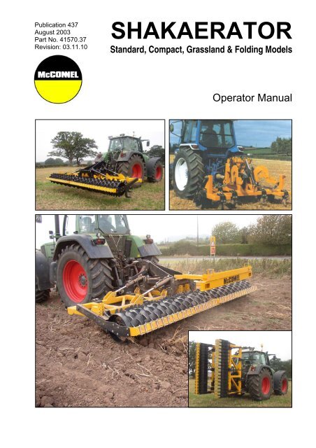
Publication 437August 2003Part No. 41570.37Revision: 03.11.10<strong>SHAKAERATOR</strong>Standard, Compact, Grassland & Folding Models<strong>Operator</strong> <strong>Manual</strong>
IMPORTANTVERIFICATION OF WARRANTY REGISTRATIONDEALER WARRANTY INFORMATION & REGISTRATION VERIFICATIONIt is imperative that the selling dealer registers this machine with <strong>McConnel</strong> Limited beforedelivery to the end user – failure to do so may affect the validity of the machine warranty.To register machines go to the <strong>McConnel</strong> Limited web site at www.mcconnel.com, logonto ‘Dealer Inside’ and select the ‘Machine Registration button’ which can be found inthe Service Section of the site. Confirm to the customer that the machine has beenregistered in the section below.Should you experience any problems registering a machine in this manner please contactthe <strong>McConnel</strong> Service Department on 01584 875848.Registration VerificationDealer Name: ……………………..…………………………………………………………….Dealer Address: …….………………………………………………………………………….Customer Name: ……………………..…………………………………………………………Date of Warranty Registration: ……/……/...…… Dealer Signature: ………………..……NOTE TO CUSTOMER / OWNERPlease ensure that the above section above has been completed and signed by the sellingdealer to verify that your machine has been registered with <strong>McConnel</strong> Limited.IMPORTANT: During the initial ‘bedding in’ period of a new machine it is the customer’s responsibilityto regularly inspect all nuts, bolts and hose connections for tightness and re-tighten if required. Newhydraulic connections occasionally weep small amounts of oil as the seals and joints settle in – wherethis occurs it can be cured by re-tightening the connection – refer to torque settings chart below. Thetasks stated above should be performed on an hourly basis during the first day of work and at leastdaily thereafter as part of the machines general maintenance procedure.TORQUE SETTINGS FOR HYDRAULIC FITTINGSHYDRAULIC HOSE ENDSPORT ADAPTORS WITH BONDED SEALSBSP Setting Metric BSP Setting Metric1/4” 18 Nm 19 mm 1/4” 34 Nm 19 mm3/8” 31 Nm 22 mm 3/8” 47 Nm 22 mm1/2” 49 Nm 27 mm 1/2” 102 Nm 27 mm5/8” 60 Nm 30 mm 5/8” 122 Nm 30 mm3/4” 80 Nm 32 mm 3/4” 149 Nm 32 mm1” 125 Nm 41 mm 1” 203 Nm 41 mm1.1/4” 190 Nm 50 mm 1.1/4” 305 Nm 50 mm1.1/2” 250 Nm 55 mm 1.1/2” 305 Nm 55 mm2” 420 Nm 70 mm 2” 400 Nm 70 mm
WARRANTY POLICYWARRANTY REGISTRATIONAll machines must be registered, by the selling dealer with <strong>McConnel</strong> Ltd, before delivery to the enduser. On receipt of the goods it is the buyer’s responsibility to check that the Verification of WarrantyRegistration in the <strong>Operator</strong>’s <strong>Manual</strong> has been completed by the selling dealer.1. LIMITED WARRANTIES1.01. All machines supplied by <strong>McConnel</strong> Limited are warranted to be free from defects in materialand workmanship from the date of sale to the original purchaser for a period of 12 months,unless a different period is specified.1.02. All spare parts supplied by <strong>McConnel</strong> Limited are warranted to be free from defects in materialand workmanship from the date of sale to the original purchaser for a period of 6 months.1.03. The manufacturer will replace or repair for the purchaser any part or parts found, uponexamination at its factory, to be defective under normal use and service due to defects inmaterial or workmanship. Returned parts must be complete and unexamined.1.04. This warranty does not apply to any part of the goods, which has been subjected to improper orabnormal use, negligence, alteration, modification, fitment of non-genuine parts, accidentdamage, or damage resulting from contact with overhead power lines, damage caused byforeign objects (e.g. stones, iron, material other than vegetation), failure due to lack ofmaintenance, use of incorrect oil or lubricants, contamination of the oil, or which has served itsnormal life. This warranty does not apply to any expendable items such as blades, flails, flapkits, skids, soil engaging parts, shields, guards, wear pads or pneumatic tyres.1.05. Temporary repairs and consequential loss - i.e. oil, downtime and associated parts arespecifically excluded from the warranty.1.06. Warranty on hoses is limited to 12 months and does not include hoses which have sufferedexternal damage. Only complete hoses may be returned under warranty, any which have beencut or repaired will be rejected.1.07. Machines must be repaired immediately a problem arises. Continued use of the machine after aproblem has occurred can result in further component failures, for which <strong>McConnel</strong> Ltd cannotbe held liable, and may have safety implications.1.08. Except as provided herein, no employee, agent, dealer or other person is authorised to give anywarranties of any nature on behalf of <strong>McConnel</strong> Ltd.1.09. For machine warranty periods in excess of 12 months the following additional exclusions shallapply:1) Hoses, external seals, exposed pipes and hydraulic tank breathers.2) Filters.3) Rubber mountings.4) External electric wiring.1.10. All service work, particularly filter changes, must be carried out in accordance with themanufacturer’s service schedule. Failure to comply will invalidate the warranty. In the event of aclaim, proof of the service work being carried out may be required.NB Warranty cover will be invalid if any non-genuine parts have been fitted or used. Use ofnon-genuine parts may seriously affect the machine’s performance and safety. <strong>McConnel</strong> Ltdcannot be held responsible for any failures or safety implications that arise due to the use ofnon-genuine parts.
2. REMEDIES AND PROCEDURES2.01. The warranty is not effective unless the Selling Dealer registers the machine, via the <strong>McConnel</strong>web site and confirms the registration to the purchaser by completing the confirmation form inthe operator’s manual.2.02. Any fault must be reported to an authorised <strong>McConnel</strong> dealer as soon as it occurs. Continueduse of a machine, after a fault has occurred, can result in further component failure for which<strong>McConnel</strong> Ltd cannot be held liable.2.03. Repairs should be undertaken within two days of the failure. Claims submitted for repairsundertaken more than 2 weeks after a failure has occurred, or 2 days after the parts weresupplied will be rejected, unless the delay has been authorised by <strong>McConnel</strong> Ltd.2.04. All claims must be submitted, by an authorised <strong>McConnel</strong> Service Dealer, within 30 days of thedate of repair.2.05. Following examination of the claim and parts the manufacture will pay, at their discretion, forany valid claim the cost of any parts and an appropriate labour allowance if applicable.2.06. The submission of a claim is not a guarantee of payment.2.07. Any decision reached by <strong>McConnel</strong> Ltd. is final.3. LIMITATION OF LIABILITY3.01. The manufacturer disclaims any express (except as set forth herein) and implied warrantieswith respect to the goods including, but not limited to, merchantability and fitness for a particularpurpose.3.02. The manufacturer makes no warranty as to the design, capability, capacity or suitability for useof the goods.3.03. Except as provided herein, the manufacturer shall have no liability or responsibility to thepurchaser or any other person or entity with respect to any liability, loss, or damage caused oralleged to be caused directly or indirectly by the goods including, but not limited to, any indirect,special, consequential, or incidental damages resulting from the use or operation of the goodsor any breach of this warranty. Notwithstanding the above limitations and warranties, themanufacturer’s liability hereunder for damages incurred by the purchaser or others shall notexceed the price of the goods.3.04. No action arising out of any claimed breach of this warranty or transactions under this warrantymay be brought more than one (1) year after the cause of the action has occurred.4. MISCELLANEOUS4.01. The manufacturer may waive compliance with any of the terms of this limited warranty, but nowaiver of any terms shall be deemed to be a waiver of any other term.4.02. If any provision of this limited warranty shall violate any applicable law and is held to beunenforceable, then the invalidity of such provision shall not invalidate any other provisionsherein.4.03. Applicable law may provide rights and benefits to the purchaser in addition to those providedherein.
EC DECLARATION OF CONFORMITYConforming to EEC Machinery Directive 98/37/EC*We,McCONNEL LIMITED,Temeside Works, LudlowShropshire, SY8 1ND. England.Declare under our sole responsibility that:Tractor Mounted CultivatorThe product (type) ……………………………………………………………………………………………………………………………………………………………….SH20, SH25, SH30, SH37, SH45, SA40 & SF50.Product Code …………………………………………………………………………..Serial No. & Date ……………………………………. Type …………………………Manufactured by the above company/* ………………………………………………………………………………………………………………………………….(* insert business name and full address if not stated above)Complies with the required provisions of the Machinery Directive 98/37/EC, * previouslyDirective 89/392/EEC as amended by Directives 91/368/EEC, 93/44/EEC and 93/68/EEC.The machinery directive is supported by;• BS EN ISO 12100:2003 Safety of Machinery. This standard is made up of twoparts; Part 1 Terminology, methodology, Part 2 Technical Specifications.• BS EN 1050 Safety of machinery - Principles of risk assessment.• and other national standards associated with its design and construction as listed inthe Technical File.The Machinery Directive is fully implemented into UK law by means of the Supply ofMachinery (Safety) Regulations 1992 (SI 1992/3073) as amended by The Supply ofMachinery (Safety) (Amendment) Regulations 1994 (SI 1994/2063).Signed …………………………..…………………………………………………….……..on behalf of McCONNEL LIMITEDResponsible PersonStatus: Chief Design Engineer Date: March 2009
LIST OF CONTENTSGeneral Information 2Specifications 3Introduction 4Safety Information 6Fitting 8Operation 14Auxiliary Equipment 18Folding Models 24Grassland Models 25Maintenance 311
GENERAL INFORMATIONRead this manual before fitting or operating the machine. Whenever any doubt existscontact your dealer or the <strong>McConnel</strong> Service Department for assistance.Use only ‘<strong>McConnel</strong> Genuine Parts’ on <strong>McConnel</strong> equipment and machineryDEFINITIONS - The following definitions apply throughout this manual:WARNING:An operating procedure, technique etc., which can result in personal injury or loss of life ifnot observed carefully.CAUTION:An operating procedure, technique etc., which can result in the damage of either machineor equipment if not observed carefully.NOTE:An operating procedure, technique etc., which is considered essential to emphasise.LEFT AND RIGHT HAND:This term is applicable to the machine when fitted to the tractor and viewed from the rear.This also applies to tractor references.Note: The illustrations in this manual are for instructional purposes only and may on occasion notshow some components in their entirety. In some instances an illustration may appear slightlydifferent to that of your particular model but the general procedure will be the same. E&OA.MACHINE & DEALER INFORMATIONRecord the Serial Number of your machine on this page and always quote this number whenordering parts. Whenever information concerning the machine is requested remember also to statethe make and model of tractor to which the machine is fitted.Machine Serial Number:Machine Model details:Dealer Name:Dealer Address:Dealer Telephone No:Dealer Email Address:Installation Date:2
SPECIFICATIONSStandard Rigid Frame Models• Available in various working widths from 2.0M up to 4.5M• Choice of 540RPM or 1000RPM vibrator unit• 600mm (24”) legs• Choice of points for shallow or deep cultivating• Option of adjustable depth wheels on certain models• Linkage kit provision on models 2.5m upwards• Shearbolt safety• Choice of Smooth, Oxford or Packer RollersCompact Models• Available in 3.0M and 4.0M working widths• Hydraulic vibration unit• 600mm (24”) legs• Choice of points for shallow or deep cultivating• Close fitting tractor coupling• Linkage arms allow for fitting of additional implements• Ratchet adjustable depth control wheels standard on 4.0m models• Choice of Smooth, Oxford or Packer RollersGrassland Models• Available in 2.0M & 2.5M working widths• Depth adjusting rear roller• Choice of 540RPM or 1000RPM vibrator unit• Choice of points for shallow or deep cultivating• Choice of 600mm (24”) fixed or 750mm (30”) breakback legs• Choice of mechanical or hydraulic breakback systemFolding Models• Available in 4.0M and 5.0M versions• Hydraulically operated folding mechanism for ease of transport• Hydraulic vibration unit• 750mm (30”) adjustable legs• Choice of points for shallow or deep cultivation• Slipper points as standard for ease of fitting• Points protector for added safety & protection• Lighting bar as standard with points protector storage facility• Packer Roller fitted as standard3
INTRODUCTION<strong>McConnel</strong> Shakaerators are multi-purpose cultivators available in various forms and sizes.They are not just ‘another linkage-mounted toolbar’; they are suitable and capable of beingutilized in the following ways:• In its simplest form it may be used as a heavy-duty cultivator.• With land wheels added for depth control it is suitable for shallow cultivations,scarifying and fallow operations.• With a power driven vibrator unit it is an all-purpose cultivation tool that gives an earthshattering effect when pan-busting or breaking new ground.• With PTO through-drive facility, power driven implements hydraulically mounted onthe rear of the main frame can be utilized for ‘seedbed’ preparation thereforeeffectively employing a one-pass technique for minimum compaction and rapidpreparation.• With ratchet operated depth control, but without through-drive facility, ground engagingimplements such as the Oxford or Flexicoil Roller may be mounted thus making itsuitable for clod breaking or for land re-settlement when operating on grass land.Frame SpecificationsCurrently within the range there are six sizes of frame available.Frame Size No. of Shanks (Legs) Guide to drawbar h.p. req.2.0 metre 5 Shank From 60 h.p.2.5 metre 7 Shank From 75 h.p.3.0 metre 9 Shank From 100 h.p.3.7 metre 11 Shank From 120 h.p.4.5 metre 13 Shank From 140 h.p.5.0 metre* 10 Shank From 200 h.p.* Folding modelProvision is made on the 2.5m, 3.0m, 3.7m and 4.5m models to be equipped with PTOthrough drive facility and hydraulic linkage for the independent mounting of an additionalimplement. An additional mounting bracket is available for the 4.5 metre frame model toallow for the mounting a second slave ram - this can be supplied as an optional extra.Folding Model Lifting Point LocationsThe illustration opposite shows the location of the lifting pointsfor optimum balance on a Folding Shakaerator when it is in theupright (folded) position with components attached.Suitable substantial lifting equipment capable of supporting theweight of the machine must always be used and the operationshould only be carried out on a firm level site.Bystanders should be kept at a safe distance from the machineat all times whist carrying out this procedure.4
ConstructionThe combination of the clamp and shank and the clamp plate permits the rigid attachmentof the shank to the toolbar using high tensile steel bolts and nuts. In the event of animmovable underground obstruction being encountered, as a safety feature, the thread ofthe nuts strip allowing the shank to ‘swing’ back.Through Drive Vibrator UnitOn all machines vibrator units may be bolted to the flange plates on the frame and areprovisioned for through drive, which is supplied as standard. There are three options ofthrough drive shaft – these are as follow:1) 540 rpm - 6 Spline.2) 1000 rpm - 1⅜” diameter (21 Spline).3) 1000 rpm - 1¾” diameter (20 Spline).IMPORTANT: On Grassland models where a grass disc assembly is fitted in the centre ofthe frame directly below the through drive, the through drive assembly must be fitted withthe flywheel nearest the rear of the frame to avoid the components colliding duringoperation - failure to observe this will result in damage to components.CAUTION!Always ensure Through Drive is fitted to the machine with the flywheel nearestthe rear of the frame when a centrally mounted Grass Disc is attached.ShanksAll standard rigid frame models use 24” clamp type shanks with a choice of either ‘knockon’ or ‘slipper’ type points. As an option grassland models are available with eithermechanical or hydraulic ‘breakback’ legs – ‘breakback’ legs are fitted with 30” shanks.Folding models use a 30” Adjustable Shearpin Shank only.5
Shank OptionsFixed Frame Models:• 24” Shank for ‘Knock On’ Points• 24” Shank for ‘Slipper’ PointsGrassland ‘Breakback Leg’ Models:• 30” Shank for ‘Slipper’ PointsFolding Models:• 30” Adjustable Shank for ‘Slipper’ PointAdjustable ShanksThe 30” shanks used on the folding models are height adjustable via combinations of holepositions located at the top of the shank; this allows the working depth of the machine tobe varied to suit particular requirements or conditions. The same shanks are utilized ongrassland models fitted with breakback legs, but it is important to stress that when used onthese models they should not be height adjusted as the working depth is controlled by therear roller only and any adjustment of the shanks would result in them fouling on the rearroller when they breakback.The correct front and rear hole height positions when used on grassland models areindicated A & B below:Shank hole positions for Grassland ‘Breakback’ ModelsCAUTION: Do not use hole positions other than those indicated above on Grassland models– failure to observe this can result in the shank fouling the rear roller during breakback.PointsAll shanks use a choice of two types of points as listed below;• Wide points for shallow cultivation down to a depth of approx 12”• Narrow points for deep cultivation down to a depth of approx 24”All folding models use ‘slipper’ points only whereas standard fixed frame models can useeither ‘knock on’ or ‘slipper’ type points dependant on the type of shank they are to befitted to.NOTE: ‘Slipper’ and ‘knock on’ points are not inter-changeable – they will only fit thespecific type of shank they were designed for.6
SAFETY SECTIONThis machine has the potential to be extremely dangerous - in the wrong hands it can killor maim; It is therefore imperative that both owner and operator of the machine reads andunderstands the following section to ensure they are fully aware of the dangers that do, ormay exist, and their responsibilities surrounding the use and operation of the machine.When the machine is not in use it should be lowered to rest on the ground. In the event ofany fault being detected with the machine’s operation it must be stopped immediately andnot used again until the fault has been corrected by a qualified technician.▲ ALWAYS ensure all operators have read and understood the operation and safetyinformation in the manual before using the machine.▲ ALWAYS inspect the work area for possible dangers or risk before starting work.▲ ALWAYS ensure all guards are in place and are kept in good condition – they are therefor your protection and the safety of others.▲ ALWAYS keep clear of any moving or rotating components.▲ ALWAYS ensure that nuts holding the shanks to the machine frame are on theunderside.▲ ALWAYS stop a working machine when other people enter a work area and onlyrestart when the area is clear of any risk.▲ ALWAYS wear protective eye shields when striking points.▲ ALWAYS ensure point protectors are fitted to folding models when in the transport orstorage position.▲ ALWAYS be alert – if any help is being given during the coupling or uncoupling ofmachines or any other equipment ensure the assistant is kept clear of risk ofentrapment.▲ NEVER wear loose or flapping clothing near a working machine▲ NEVER permit anyone to ride on the machine, whether in transport or in work.▲ NEVER approach a working machine or attempt any kind of maintenance on a workingmachine.▲ NEVER work under a machine that is unsupported or raised on the tractors hydrauliclift – always use suitable substantial supports placed under the machine on a firm levelwork area.▲ NEVER allow bystanders near a working machine – ensure they remain at a safedistance from the machine.▲ NEVER permit children to play on a machine even when removed from the tractor andstored.7
FITTINGTractor Power RequirementsIt is impossible to give any hard and fast figures on horsepower requirements asground conditions can vary enormously. The figures quoted in the frame specificationsection are advisory only and the removal or addition of one or two shanks might benecessary to obtain the optimum performance from the tractor.A marked increased in the draft requirement will be necessary under moist conditionswhen the vibrations are more readily absorbed by the damp soil.Front End WeightIt may be found to advantageous to apply front-end weight to some smaller and mediumpowered tractors. The amount of weight necessary can only be determined by localcircumstances. It should be borne in mind that any tendency of the tractor to rise on thefront end will produce a corresponding lowering of hitch points and in doing so, the angleof penetration of the shanks is further increased.Tractor LinkageIt is essential that only the correct linkage arms for each particular tractor are used with theShakaerator. The arms have been properly matched with the horsepower of the tractorand should be more than ‘just’ adequate. Nothing on the Shakaerator offers protectionagainst the failure of unmatched, repaired, badly worn, weak or below category tractorlinkage.Failure of either of the tractor's draft links can cause the tractor to run away from oneend of the implement or in the case of the top link, the implement to tip forwards. Theresult could mean that the PTO shaft assumes an impossible angle that may bend it ortear out the yokes or their bearings. Even the PTO stub shaft in the tractor and thedrive spline of the vibrator unit could be damaged.Under no circumstances should tractors operate in tandem to gain extra traction. It is farmore practicable to make two or three passes over the ground with one tractor whileincreasing the depth on each pass.StabilizersThe implement must be capable of some side-to-side movement in relation to the tractortherefore stabilizer chains or sway bars must be adjusted to allow for this. They shouldhowever be tightened up to prevent side sway when traveling on the highway. In fieldoperations stabilizer bars that hold the implement rigid should not be used.Draft ControlUse of draft control is beneficial to traction in reducing wheel slip thereby also reducingtyre wear and saving fuel. Refer to individual tractors instruction book for detailed guidanceon the best location for top link fitting.For mounting the cultivator on linkage behind crawler tractors, the draft links should beallowed to 'float' - provision for this is usually made in the hydraulic control valve.Do not use position control for regulation of depth. This should be done with the aid ofdepth wheels or rear roller.8
PTO AngleThe angle of operation of universal drive shafts has recommended limits. On tractors withlow PTO output shafts the angle becomes acute when the implement is lifted to itsmaximum travel. This should not present a hazard as the PTO drive should be disengagedbefore lifting the implement clear of the ground or alternatively the lift height should berestricted.The vibrator unit on current machines is bolted to two flange plates. The vibrator can beadjusted vertically by selecting the most suitable holes in the plates, which give theminimum deflection of the shaft when in operation. It should be noted that the rear coverplate on the through drive unit can be turned over to increase the adjustment range.Machine AssemblyThe Shakaerator is despatched with the vibration unit mounted in position on the frameand, where applicable, the land wheels fixed in the stowage position. The remainingitems, shanks, clamps, slippers, PTO shaft, nuts and bolts etc., are despatchedseparately.• Place the frame (tower up) on an even flat surface.• Place the top link attachment bracket, with linkage pin holes forward and inclinedupwards in the centre of the tower cross-bar. Fasten in position with clamp plate,bolts, washers and the self locking nuts. The washer must always go on the clampplate.Nuts must be tightenedevenly and care taken toensure there is maximumsurface contact between theclamp and frame. Finaltightening of the nuts shouldbe diagonally and notexceed 60 ft lbs torque.NOTE:4.5 metre frames only - thetop link attachment isassembled to the framewithout using washers.IMPORTANT: On some tractors, which have extra long draft links, there is a risk of thetop link only having a few threads of engagement when the machine is mounted. Shouldthis be the case, it is permissible to mount the top hitch bracket in an inverted positionfor greater thread engagement.• On 2.0m, 2.5m and 3.0m machines, raise the front of the frame approximately 5”(125mm) from the ground, attach the linkage arm attachment brackets, holes forwardand inclined upwards 5” (125mm) outside the tower uprights and clamp in position.• Attach the frame of the Shakaerator to the tractor's three point linkage with the pinsand linch pins provided; use the highest hole in the bottom hitch bracket unless thereis a clearance problem, this is to give adequate top link force for draft control.10
Depth WheelsThe depth wheels, where applicable, are hinge mounted and are adjusted by means of ahandled ratchet.‘Knock On’ PointsThe points must now be assembled on the shanks. It must be decided which type of pointto fit, Longlife or Delta, the choice of which will primarily be dependant on the depth ofcultivation required. Check that the point socket is empty of any form of debris. The pointmust be tapped firmly onto the Shakaerator shank foot until the indentation in the shanksocket engages the raised 'pip' cast in the shank.If, by using reasonable force, the point will not engage far enough onto the shank foot, it ispermissible to grind the corners of the shank until sufficient engagement is obtained. Careshould be taken not to over grind, which would result in a loose fit and possible loss of thepoint when working.NOTE: Older machines that were fitted with ‘knock on’ type points were dispatched with along handled hammer, the head of which was made of mild steel so there was littlelikelihood of chipping the hardened steel point when striking it during fitting. As an addedprecaution eye shields were also supplied with the machines; when fitting these types ofpoints eye shields must always be worn.When fitting points to shanks already fixed to the machine stand to the rear or to one sideof the frame when using the hammer, do not crouch beneath the frame.‘Slipper’ PointsAttachment of the ‘slipper’ type point is achieved by sliding the point onto the foot of theshank, which, when in position may be angled downwards at the front to permit the ‘toe’ ofthe wear shin to locate between the shank and the upper rear of the point – the shin mayrequire ‘tapping’ into position to ensure a tight fit is achieved, the top of the shin is thensecured into position on the shank with its fixing bracket, nut and bolt.NOTE: Ensure when ordering replacement points that the correct type of points are orderedto suit the shanks as they are not interchangable with each other – a ‘slipper’ point will notfit a ‘knock on’ type shank and visa versa.WARNING: Always ensure protective eye shield are worn when ‘knocking’points onto shanks.Fitting Shank Assemblies (Legs)The shank set-up is governed by the work to be done. Normal shank arrangement is tohave one more assembly mounted on the rear toolbar than on the front.The shank assemblies should be fitted to the toolbar in the required position and the nutstightened evenly and diagonally to a torque setting of 225-255 ft.lbs (305-350Nm).PTO ConnectionConnect up the PTO shaft ensuring that it does not 'bottom out' in any position.11
SHANK POSITIONS – Series 2 models12
General View (Standard Model)13
OPERATIONSpeedWhen first putting the Shakaerator into operation, the tractor's forward speed should belimited to less than 3mph (5kph) with the engine speed adjusted to give a PTO shaftspeed of 540RPM. Forward speed can be gradually increased later as experience withthe machine is gained.The points should be on or in the ground before the PTO is engaged and similarly shouldbe disengaged before lifting the points out of the ground. On tractors that share acommon drive to both the hydraulic lift and PTO engine speed should be reduced to aminimum and the machine lifted only as far as is necessary.Depth ControlTo achieve maximum depth with a lower draft requirement it is possible where necessaryto make more than one pass over the ground increasing the depth each time.Alternatively, some shanks can be removed.Calibration marks are cast into the sides of the shanks; centimetres on one side andinches on the other to assist the operator in maintaining more precise depth control.These are approximate calibrations and, obviously, will vary as the points wear.In setting the depth, it may be an advantage to pull the points into the earth to the depthrequired without engaging the PTO drive, the depth wheels can then be lowered to theground.In matching the holes on the adjustment pins, select the nearest one, shallower, than thedepth required; the normal action of the point is to pull in deeper. The wheels exert apositive, but not heavy pressure to hold the point from penetrating further. Even so, it issometimes necessary to reset the depth wheels to a shallower notch after the start ofdigging as the wheels will generally sink into the disturbed earth and increase the depthof penetration.Depending on which points are selected and how they are used, the Shakaerator can doat least some of the work of a sub-soiler, a chisel plough and a cultivator. Its greatest useis to loosen soil that has been compacted to a higher density then is desirable foroptimum crop production. This compaction may be at the surface, deep compaction or asa pan. The latter is a thin impervious layer caused by a plough or other implementsmearing the soil whilst working in wet conditions.For folding and grassland models the working depth is determined by the height settingof the rear roller(s).Point SettingsNarrow points (Longlife Points)These are the normal choice for deep cultivation - the points will lift and shatter the soilstructure with low draft and minimum mixing.Wide points (Delta Points)Wide points will break up a bigger area of ground and can therefore be spaced furtherapart - this is particularly useful for shallow cultivations.Any set up of the Shakaerator working at depths below cultivation, i.e. below 8"(200mm), has the great advantage of loosening the soil without mixing or inverting. Clodsare not formed or brought to the surface.14
Working DepthThe depth to which the Shakaerator can best be used depends entirely on soil type andmoisture content, the combination of these factors produces a critical depth, below thisdepth less soil is loosened and the tractor draught force is considerably greater. Down tothe critical depth the breakout pattern is similar to figure 1. Below the critical depth figure2 applies. This can often be recognised from the surface but is very clearly seen bydigging the profile.Figure 1 is the pattern produced by the narrow points and figure 3 is the pattern of thewide points – the wide points produce a much greater loosened area.Figure 4 shows the wide point working below the critical depth. This critical depth withthe wide points may be lower than for the narrow points.The reason for this critical depth is that in for example figure 3 the soil has beenloosened upwards because that is the direction of least resistance. In figure 4 theresistance to upwards movement is greater and it is easier for the soil to compactsideways than to loosen upwards. The very small amount of loosened soil at the top ofthe tine is because the loosening has been done by only the width of the shank. Thesides of the compacted channel may be smeared and it is obvious that this is a verydetrimental condition in which to leave the soil.15
Tine SpacingThe tine spacing is related to the working depth for each type of point. With the narrowpoints the spacing should be 1.2 - 1.5 times the depth. This gives the least draughtforce and most even surface finish (Fig.5) with complete break up of the soil profile.Figure 6 shows the same tines too far apart giving incomplete break up. With the widepoints the spacing can be 2 - 2.2 times the working depth (Fig.7).Shallow Leading TinesDraught force can be reduced and the amount of soil loosened increased by usingshallow tines in front of long ones. The 460mm shanks should be mounted to each sideof the 610mm shank and not directly in front. Figure 8 shows an ideal setup.16
Re-compactionLoosened soil is extremely prone to re-compaction by subsequent traffic especially in wetconditions when loosening can be achieved by using wide points and shallow leading tinesbut any re-compaction will be more severe than the original problem. For this reason it isnot a good idea to use two passes in different directions but to try to combine the two inone pass with for example shallow leading tines.If power is inadequate to cover the full width of the toolbar it is better to remove theshanks in the middle of the frame, which will leave an undisturbed strip of ground in thecentre. On the return bout across the field the tractor wheels should be positioned on theunmoved strip to complete the cultivation on a straddle and overlap principle.Underground ObstructionsIf a point becomes jammed in a root or rock operating the vibrator slowly and alternativelyattempting to raise and lower the frame can sometimes free it. Should this fail, engagereverse gear and with the vibrator unit still operating back-up slightly. This will usuallyrelease the shank but a check should be made immediately to ensure that the point hasnot remained embedded in the obstruction.Fail-SafeMost types of 'fail-safe' arrangement on farm machinery such as shear bolts, pins, slipclutches etc., are designed to protect the implement in the event of overloading orstriking an obstruction. On the Shakaerator however, the 'fail-safe' is designed to protectthe tractor. The two top bolts and nuts securing the clamp shanks to the frame aredesigned to ‘fail’ if a really solid obstruction is met.It is vital that only ‘Genuine <strong>McConnel</strong> Parts’ are used for the replacement of boltsand nuts, as they are of special grades specific to the design requirement. In actionthe threads of the two upper nuts will shear off, the shank may then twist around thetoolbar. To release, the shank should be swung back into its normal position and theupper nuts, bolts and washers replaced.There is a possibility that the nuts will fail if the bolts are loose, if the hardened steelclip washers are omitted from the top of the clamp plates or if the speed is excessive inrough ground.It is most important that only the correct nuts and bolts are used, they should bechecked regularly and retightened. Only an accurate and tight fit of the clamps on thetoolbars provides the ideal transmission of vibration to the points. On initial start up allnuts and bolts should be checked for tightness after one hour’s operation or in the caseof very rough ground, after the first fifteen minutes. Nuts should be tightened uniformlyand as tight as possible using a normal spanner. Extra leverage should not be usedotherwise the thread within the nuts could be weakened and strip.17
AUXILIARY EQUIPMENTTrailed ImplementsAttachments that can be fitted behind the Shakaerator such as the roller do not requirehydraulic linkage. The depth control wheels are removed and the ratchet adjusters areused on the trailed implement to control depth.When coupling the tractor to the Shakaerator use the lowest practicable hitch point, andwhere possible, turn the mounting bracket over to achieve this. Use the highest possiblehitch point for the top link mounting. Forces applied through the top link are reducedwhen operated in this way and the risk of top link failure is minimised.Where it is not possible to obtain the geometry with the tractor's existing top link, a<strong>McConnel</strong> Heavy Duty Top Link Assembly (Part Number 7115275) is available. Closedlength (pin centres) 800mm (2’ 7½”) open length 1150mm (3’ 8½”).If there is ever any doubt of the strength or serviceability of the tractor's top link, then a<strong>McConnel</strong> top link should be used. Any failure of the top link could result in seriousdamage to the through-drive assembly.OperationTo correctly set the machine for use the roller should be raised – the Shakaerator is thendrawn forward into the ground. When the points have reached the required depth the rollershould be lowered to the ground.18
Shear PinsAs the roller is mechanically held in position by the ratchet adjusters, no movementrelevant to the main frame is possible. When the roller run over a large rock or stump itsaction would try to lift the shanks out of the ground. If it fails to do so, the body of the rollerwould be damaged or bent. To avoid this accidental damage special shear pins are fittedin the lower link ends to the ratchet adjusters. In the event of these shear pins being‘sheared’, do not substitute an ordinary bolt or metal rod.BallastIf extra weight is required when using the roller, water ballast can be added. Precautionagainst frost should be taken in cold climates by either storing in a frost free building ordraining the roller.Hydraulic LinkageTo enable an implement being worked in conjunction with the Shakaerator to becontrolled independently, an optional hydraulic linkage kit is available to accommodatealmost any Cat.ll three-point linkage implement. Using a single acting ram, the linkage ispowered by an external services supply from the tractor. Stabilizer chains are suppliedas standard and optional Cat.1 or 11 top link ends supplied as required.The drop stops bolts on to the inside face of the draft link and by inverting, give two fixedheight working positions for the link ends. It is also advantageous as the combination canbe lifted at the end of the row using just the tractor's linkage without altering the existingalignment of the PTO shaft.For hitching the implement or for operating without stops the top bolt can be loosened,the bottom one removed and the stop pivoted down and out of the way. The bottom boltis replaced which then acts as a latch to prevent the stop swinging back into a 'foul'position.Hydraulic Linkage Kit- allows independent control of additional implements19
Hydraulic Lift Assister Ram (Optional Extra)On 3.7m and 4.5m frames only, additional lugs are welded to accommodate an assisterram when an extra heavy implement is to be mounted. The extra hydraulic hose requiredis junctioned into the initial supply with a 'T' piece.It should be noted that all linkage rocker shafts are provisioned for accepting the rod endof any extra ram leaving it for the customer to weld additional lugs to the frame if it isenvisaged that a very heavy implement is to be attached to any of the alternative frames.Hydraulic Lift Assister Ram KitPower Driven ImplementsGreat care should be taken when using a power driven implement behind the Shakaeratorto ensure that the implement’s drive shaft is not subjected to acute angles when in motion.The tractor's PTO shaft must be disengaged before lifting the unit on the linkage. Toaccommodate a variation in shaft operating heights for different implements the whole ofthe through-drive assembly can be raised or lowered by means of a range of adjustmentholes on the vertical mounting plates. Caution should also be exercised that theimplement's drive shaft does not 'bottom out' when raised to its maximum on the linkage.Also check the full range of operation of the linkage to ensure that the drive shaft does notfoul any part of either implement.20
Power Take Off GuardAt all times when an auxiliary implement is not in use the stub shaft guard should besecured in position.When operating auxiliary equipment the following applies:The rear section of the stub shaft guard is removed. As shown, the guard is suitable for thecentral and top mounting positions of the through drive shaft. For the lower position theguard mounting plate is inverted and the top guard assembled on secondary flange 'A'provided. Remember these guards are a legal requirement and on no account should theShakaerator be used on its own or in a combination without the relevant guards securely inposition.Illustration Note: The illustration above shows an early through drive – current machineswill have a shorter through drive shaft with a shorter spring and the rear bearing andbearing back block inboard of the through drive mounting plate.21
Turf DiscsSpring loaded turf discs are available, which are supplied as an option, when it is desiredto create a minimal surface disturbance in pastureland. The normal application is tomount the discs on the front toolbar in a position where they will slice the turfimmediately in front of the following shank.Turf discs are normally used with a roller. It is not possible to use the outermost discmounting position with wheels installed. A typical arrangement of four discs and shankson a 3m frame is shown below. Up to six discs and shanks can be used on a 4.5mframe.In some circumstances it is possible to fit a disc in the centre, but in this positionclearance beneath the frame is limited, so that the maximum working depth would bereduced.22
Shin GuardsShin guards can be strapped to the leading edge of the shank. They are easily fitted orremoved after releasing the point and removing the nut and bolt that secures them at thetop of the shank.Shin GuardCAUTION! Do not attempt to hard face or otherwise weld the shank - this woulddestroy the shank’s properties.Shanks are made from extremely tough abrasive resistant steel and are subjected to aspecial heat treatment during manufacture. Do not attempt to hard face or otherwise weldthe shank as this will destroy the shank’s properties. Owners are reminded that nowarranty can be entertained on shanks that show evidence of welding.Shin guards, which can be supplied as an option, are made of special hard steel that willreadily accept hard-face welding reinforcement.23
FOLDING MODELSFolding models can be raised into the upright position for ease of transportation andstorage, both ‘wings’ of the machine are raised simultaneously – they cannot be raisedindependently of each other – when unfolding ensure the point protection guards havebeen removed and stowed in their storage location on the light bar before releasing the‘locking’ latch and lowering the wings into the work position.WARNING: Ensure there is sufficient space around the machine beforeattempting to unfold it, and that all persons are kept at a safe distance frommachine.NEVER FOLD OR UNFOLD A MACHINE WITH PERSONS ON OR NEAR IT – ENSUREBYSTANDERS ARE KEPT A MINIMUM DISTANCE OF 5 METRES WHILST UNFOLDING THEMACHINE.Roller Height Adjustment (Folding Models)With the machine raised clear of the ground select the highest desired position on theadjustment bracket for the roller to achieve and insert the ‘roller height pin’ into a suitablehole for that height on the adjustment bracket, this will need to be repeated at both ends ofeach roller, ensuring the same respective hole is selected on each. The machine may beworked with just these higher roller height pins inserted - this will allow continual rollingand compaction of the surface ‘riding’ any machine undulations up to a point where themachine is removed from the ground.Alternately after inserting the higher pins the machine can be lowered, the points drawninto the ground to the desired depth, and lower pins located through the roller arms andframe to ‘lock’ the rollers to a determined height – in this mode the rollers will be ‘fixed’therefore raising the machine will also raise the rollers.WARNING! It is vital that the rollers are locked into the lowest possible positionwith their pins before folding the machine – failure to observe this will result inthe rollers contacting each other causing damage to the machinePoint Protection GuardsFolding models are supplied as standard with ‘Point Protector Guards’ these attach ontoeach rows of points with spring fixings. These guards are supplied not only to protect themachine from accidental collision damage but more importantly for the safety of othersespecially when transporting the machine on the highway or in public places.It is therefore good practice and a wise precaution to ensure they are fitted at all timeswhilst the machine is in transport or when stored. When the machine is being worked theprotectors can be stowed in their storage housing on the lighting bar.24
GRASSLAND MODELSRoller HeightThe working depth of grassland models is determined and regulated by the height at whichthe rear roller is set. A selection of holes in the roller bracket attachment point on eachside the rear of the frame allows for a choice of height settings at which to set the roller.After selecting the desired height the ‘dog legged’ roller brackets are locked in positionwith the pins and lynch pins provided. Pin position ‘A’ indicated in the illustration belowregulates the upper height and pin position ‘B’ the lower height. Ensure at all times thatmatching hole positions are selected on each side of the machine.NOTE: It is advisable during transportation of the machine that the roller is locked ‘tight’ inposition to avoid risk of the roller bouncing when traveling over rough terrain – this willreducing stress on components and increase stability of the carrying vehicle.25
Point TypesNarrow points (Longlife Points)These are the normal choice for deepcultivation; the points will lift and shatter thesoil structure with low draft and minimummixing.Longlife PointWide points (Delta Points)Wide points will break up a bigger area ofground and can therefore be spaced furtherapart; particularly useful for shallowcultivations.Delta Point‘Knock On’ Point Attachment – 24” Leg Models onlyGrassland Shakaerators with 24” Legs are fitted with ‘knock on’ type points. The machinesare despatched with a special long handled hammer and safety glasses specifically for usein fitting these types of points; the head of the hammer is made of mild steel to reduce thepossibility of ‘chipping’ the hardened points when striking them during fitment.‘Knock On’ Point FitmentCheck that the point socket is empty of any form of debris. The point must be tapped firmlyonto the Shakaerator shank foot until the indentation in the shank socket engages theraised 'pip' cast in the shank.If, by using reasonable force, the point will not engage far enough onto the shank foot, it ispermissible to grind the corners of the shank until sufficient engagement is obtained. Careshould be taken not to over grind, which would result in a loose fit and possible loss of thepoint when working.WARNING! When fitting these types of points eye shields must always be worn.When fitting points to shanks already fixed to the machine stand to the rear or to one sideof the frame when using the hammer, do not crouch beneath the frame.‘Slipper Point’ Attachment – 30” Leg Models onlyGrassland Shakaerators use<strong>McConnel</strong> ‘Slipper’ Points whichare securely held in position oneach leg by a Grassland Clamp(Part Number 21347.03) asshown opposite.It is important to ensure correctfitment of the clamp and point tothe leg.Incorrect fitment can result inthe point coming loose or adriftduring work.The correct procedure for fitment is shown on the following page.26
Grassland Clamp & Point Fitment – 30” Leg Models onlySlacken off clamp block retaining nut.Screw adjuster bolt to its fully in position.Locate clamp onto base of the leg with adjuster bolt to the rear - do not secure at this stage.Locate slipper point over toe of leg as far as it will go ensuring tight contact on underside ofleg - slide the nose of the clamp fully into the upper slot of the point as far as possible.Tighten adjuster bolt and clamp block retaining nut to achieve a tight secure fitment.27
Breakback Protection SystemsThere are 2 types of breakback protection systems available for the GrasslandShakaerator; these are Mechanical Breakback or Auto-Reset Breakback.NOTE: Early Auto-Reset machines utilised hydraulic accumulators and rams to providebreakback - from late 2010 onwards this system is superseded by self-contained gasstruts.Mechanical Breakback SystemThis system works on a shear bar method wherea contact force with an object in excess of ameasured limit will shear the locking bar of theleg allowing it freedom to pivot backwards andupwards, thus protecting major components fromdamage. Each shear bar has a total of 4 ‘lives’before a replacement will be required.The ‘4 Lives’ Shear Bar (Part No. 22520.54)NOTE: It is important when replacing shear bars that genuine <strong>McConnel</strong> replacements (Part No. 22520.54) areused as these are specially designed to shear under a pre-determined force. Use of non-genuine parts willrisk expensive damage to the machine and/or tractor. Under no circumstances should the shear bolt bereplaced by a bolt or a metal rod.Hydraulic Auto-Reset Breakback System (EarlyMachines)This system provides protection via hydraulic rams andaccumulators; each leg is held in the work position by ahydraulic ram pressurized by pre-charged accumulators.When an object is struck producing a force in excess of ameasured limit, the oil in the rams is forced back into theaccumulators allowing the leg to breakback. Once theobstruction has been passed the accumulators will return theoil to re-pressurize the ram which then automatically returnsthe leg into the work position.DANGER! Keep clear of hydraulic legs when they arein the breakback position, residual pressure in thesystem may cause them to move without warning.28
Pressurising the Hose SystemThe hose system from the tractor spool valve should be pressurised to 30-40BAR, aninline pressure gauge is fitted for both measuring and checking of the pressure. Pressurisethe system by operation of the tractor spool valve until the correct pressure is reached, thespool valve must be set tominimum flow during thisprocedure to allow control of theflow rate into the system andalso prevent the relief valve frombeing ‘overwhelmed’ with oil.Once the correct pressure isachieved the tractor spool valveshould be returned to theneutral position.The pressure should always bechecked prior to work and atregular intervals thereafter toensure pressure remains withinthe specified limits.ShanksShanks are made from extremely tough abrasive resistant steel and are subjected to aspecial heat treatment during manufacture. Do not attempt to hard face or otherwise weldthe shank as this will destroy the shank’s properties. Owners are reminded that nowarranty can be entertained on shanks that show evidence of welding.Shin guards, which can be supplied as an option, are made of special hard steel that willreadily accept hard-face welding reinforcement.CAUTION! Do not attempt to hard face or otherwise weld the shanks - this willdestroy the shank’s properties.Hydraulic System (Hydraulic Breakback Models only)The hydraulic system for hydraulic breakback models comprise of single acting ramsplumbed into three hose runs. The circuit is primed at the factory prior to delivery of themachine and will only require bleeding when hydraulic components are replaced.Bleeding the Hydraulic SystemBefore attempting to bleed the system the oil safety note below should be read and theadvice strictly adhered to.The 3 rams located at the ends of the hose runs are fitted with end caps, these will be the2 outer rams and the centre ram. With the supply hoses attached to the tractor, loosen theend caps of the 3 rams – do not loosen too much, ½ turn should be sufficient to allow theair to escape. Start the oil flow and observe the end caps, when oil begins to escape fromthe end caps, stop the flow and re-tighten the end caps.NOTE: Suitable containers should be used to catch any oil that escapes from the system –dispose of oil as advised by the manufacturer.Oil SafetyAlways wear suitable eye, hand and body protection when working withhydraulic oils – refer to the oil manufacturers’ safety information for furtherdetails and advice.Escaping oil under pressure is extremely dangerous – never check for leakswith your hand, use a piece of cardboard or similar material held at arms length.29
AccumulatorsMachines with hydraulic breakaway utilise tandem accumulators that are pre-charged withnitrogen when they leave the factory. Valves are located on the top of the accumulatorcylinders for charging purposes only – do not open the valves or release the pressure;re-charging the accumulators requires the correct use of specialised equipment and mustonly be performed by the manufacturer or dealers qualified in this subject.Gas StrutsLater version auto-reset machines are equipped with Nitrogen filled Gas Struts; these arefactory pre-charged to 100Bar and will not require any intervention or maintenance by theoperator. The filling valve located on the base of the strut must not be opened or interferedwith under any circumstances – any adjustments or maintenance to this component mustonly be carried out by specialists or the manufacturer.30
MAINTENANCEService and MaintenanceMaintenance of the Shakaerator is limited to annually cleaning and re-packing the wheelbearings with grease, regularly checking the points for security and the clamp bolts fortightness. Rear roller and roller bracket greasing points should be lubricated on a dailybasis prior to work and before storage of the machine.Power Take Off ShaftThe PTO drive shaft and its guarding should be regularly examined to ensure that it is ingood condition. The two halves of the plastic guard should be checked on a daily basis toensure that they spin freely on the shaft. Ensure that all PTO shaft guard are fitted withtorque chains to stop them from spinning with the shaft. Lubricate the shaft as indicated inthe individual shaft leaflet provided with this component.Vibrator UnitThis unit is used on all machines. The vibrator weight is carried by a shaft mounted in ‘selfaligning’sealed ball bearings at each end. The bearings are housed in cast blocks inwhich the grease fitting is located. Grease passes into an annulus machined in the blockfrom where it is forced into the bearing through a hole in the periphery of the outer racebearing.CAUTION: It is of the greatest importance that these bearings are greased very sparingly.Excessive grease will blow out the seals and allow dust and dirt to enter the bearing anddamage it. Once per season using a single stroke from a small push type domestic greasegun should be sufficient.The vibrator weight is mounted on the shaft and allowed limited movement bycompression of a spring against friction discs. Neither the bushes on which the weightrotates or the friction discs at either end should be lubricated. The tension applied on thefriction discs is correct when the spring has been compressed to a length of 2⅞” (70mm).CAUTION: Regularly check the tightness of the through drive mounting bolts. Anymovement can elongate the bolt holes and damage the bearing blocks. Tighten to a torqueof 200 ft.lbs (275Nm).31
<strong>McConnel</strong> Limited, Temeside Works, Ludlow, Shropshire SY8 1JL. England.Telephone: 01584 873131. Facsimile: 01584 876463. www.mcconnel.com


