GE FANUC CONTROL - Flint Machine Tools, Inc.
GE FANUC CONTROL - Flint Machine Tools, Inc.
GE FANUC CONTROL - Flint Machine Tools, Inc.

You also want an ePaper? Increase the reach of your titles
YUMPU automatically turns print PDFs into web optimized ePapers that Google loves.
<strong>GE</strong> <strong>FANUC</strong> <strong>CONTROL</strong><br />
MAINTENANCE MANUAL<br />
FADAL MACHINING CENTERS, LLC<br />
<strong>FANUC</strong> MAINTENANCE MANUAL<br />
Corporate Office ...................................... phone (818) 407-1400............................. fax (818) 407-0020<br />
Service / Parts......................................... phone (818) 727-2100............................. fax (818) 407-1004<br />
Programming Support ............................. phone (818) 727-2100............................. fax (818) 407-0061<br />
support@fadal.com<br />
20701 Plummer Street, Chatsworth, California 91311 USA
FADAL MACHINING CENTERS<br />
AUGUST 2005
TABLE OF CONTENTS<br />
<strong>FANUC</strong> MAINTENANCE MANUAL<br />
1.0 SPECIFICATIONS . . . . . . . . . . . . . . . . . . . . . . . . . . . . . . . . . . . . . . . . . . . . . . . . . . . . . . . . . . . . . . . . . . . 1<br />
1.1 ILLUSTRATIONS & DATA FOR ALL VMC MODELS . . . . . . . . . . . . . . . . . . . . . . . . . . . . . . . . . . . . . . .2<br />
1.1.1 VMC 2216 . . . . . . . . . . . . . . . . . . . . . . . . . . . . . . . . . . . . . . . . . . . . . . . . . . . . . . . . . . . . . . . . . . . . . . . . . . . . . . . . . . . . . . 2<br />
1.1.2 VMC 3016. . . . . . . . . . . . . . . . . . . . . . . . . . . . . . . . . . . . . . . . . . . . . . . . . . . . . . . . . . . . . . . . . . . . . . . . . . . . . . . . . . . . . . 4<br />
1.1.3 VMC 4020 . . . . . . . . . . . . . . . . . . . . . . . . . . . . . . . . . . . . . . . . . . . . . . . . . . . . . . . . . . . . . . . . . . . . . . . . . . . . . . . . . . . . . . 6<br />
1.1.4 VMC 6030 . . . . . . . . . . . . . . . . . . . . . . . . . . . . . . . . . . . . . . . . . . . . . . . . . . . . . . . . . . . . . . . . . . . . . . . . . . . . . . . . . . . . . . 8<br />
1.1.5 VMC 8030 . . . . . . . . . . . . . . . . . . . . . . . . . . . . . . . . . . . . . . . . . . . . . . . . . . . . . . . . . . . . . . . . . . . . . . . . . . . . . . . . . . . . . .10<br />
1.1.6 VMC 3020 . . . . . . . . . . . . . . . . . . . . . . . . . . . . . . . . . . . . . . . . . . . . . . . . . . . . . . . . . . . . . . . . . . . . . . . . . . . . . . . . . . . . . .12<br />
1.1.7 VMC 4525 . . . . . . . . . . . . . . . . . . . . . . . . . . . . . . . . . . . . . . . . . . . . . . . . . . . . . . . . . . . . . . . . . . . . . . . . . . . . . . . . . . . . . .14<br />
1.1.8 VMC 6535 . . . . . . . . . . . . . . . . . . . . . . . . . . . . . . . . . . . . . . . . . . . . . . . . . . . . . . . . . . . . . . . . . . . . . . . . . . . . . . . . . . . . . .16<br />
1.2 FADAL BOLT TORQUE SPECIFICATIONS . . . . . . . . . . . . . . . . . . . . . . . . . . . . . . . . . . . . . . . . . . . . . 18<br />
1.2.1 2216 & 3016 TABLE . . . . . . . . . . . . . . . . . . . . . . . . . . . . . . . . . . . . . . . . . . . . . . . . . . . . . . . . . . . . . . . . . . . . . . . . . . . . . .19<br />
1.2.2 3020 & 4525 TABLE . . . . . . . . . . . . . . . . . . . . . . . . . . . . . . . . . . . . . . . . . . . . . . . . . . . . . . . . . . . . . . . . 20<br />
1.2.3 4020 TABLE . . . . . . . . . . . . . . . . . . . . . . . . . . . . . . . . . . . . . . . . . . . . . . . . . . . . . . . . . . . . . . . . . . . . . 21<br />
1.2.4 6030 TABLE . . . . . . . . . . . . . . . . . . . . . . . . . . . . . . . . . . . . . . . . . . . . . . . . . . . . . . . . . . . . . . . . . . . . . 22<br />
1.2.5 8030 TABLE . . . . . . . . . . . . . . . . . . . . . . . . . . . . . . . . . . . . . . . . . . . . . . . . . . . . . . . . . . . . . . . . . . . . . 23<br />
1.2.6 6535 TABLE . . . . . . . . . . . . . . . . . . . . . . . . . . . . . . . . . . . . . . . . . . . . . . . . . . . . . . . . . . . . . . . . . . . . . . . . . . . . . . . . . . . .24<br />
1.2.7 T-SLOTS FOR ALL TABLES. . . . . . . . . . . . . . . . . . . . . . . . . . . . . . . . . . . . . . . . . . . . . . . . . . . . . . . . . . . 25<br />
1.3 RECOMMENDED MAINLINE FUSES / CIRCUIT BREAKERS . . . . . . . . . . . . . . . . . . . . . . . . . . . . . . 26<br />
2.0 PRE-INSTALLATION PROCEDURES . . . . . . . . . . . . . . . . . . . . . . . . . . . . . . . . . . . . . . . . . . . . . . . . . . . 27<br />
2.1 FOUNDATION . . . . . . . . . . . . . . . . . . . . . . . . . . . . . . . . . . . . . . . . . . . . . . . . . . . . . . . . . . . . . . . . . . . . 28<br />
2.2 SHIPPING DIMENSIONS . . . . . . . . . . . . . . . . . . . . . . . . . . . . . . . . . . . . . . . . . . . . . . . . . . . . . . . . . . . 32<br />
2.3 POSITIONING . . . . . . . . . . . . . . . . . . . . . . . . . . . . . . . . . . . . . . . . . . . . . . . . . . . . . . . . . . . . . . . . . . . . 33<br />
2.4 AIR SUPPLY . . . . . . . . . . . . . . . . . . . . . . . . . . . . . . . . . . . . . . . . . . . . . . . . . . . . . . . . . . . . . . . . . . . . . 34<br />
2.5 ELECTRICAL GROUNDING . . . . . . . . . . . . . . . . . . . . . . . . . . . . . . . . . . . . . . . . . . . . . . . . . . . . . . . . . 35<br />
2.5.1 PRIMARY GROUNDING . . . . . . . . . . . . . . . . . . . . . . . . . . . . . . . . . . . . . . . . . . . . . . . . . . . . . . . . . . . . . 35<br />
2.5.2 SUPPLEMENTAL GROUNDING . . . . . . . . . . . . . . . . . . . . . . . . . . . . . . . . . . . . . . . . . . . . . . . . . . . . . . . . 35<br />
2.6 CHECKING GROUNDING INTEGRITY OF FADAL VMCS. . . . . . . . . . . . . . . . . . . . . . . . . . . . . . . . . . 37<br />
2.6.1 SPECIFICATION -GROUNDING FOR THE FADAL MACHINE . . . . . . . . . . . . . . . . . . . . . . . . . . . . . . . . . . . . . . . . . . . . .37<br />
2.6.2 INSPECTION - CHECK GROUND WIRE COMING INTO VMC . . . . . . . . . . . . . . . . . . . . . . . . . . . . . . . . . . . . 37<br />
2.6.3 VERIFICATION - CHECK GROUNDING INTEGRITY WITH FLUKE METER . . . . . . . . . . . . . . . . . . . . . . . . . . . . 37<br />
2.6.4 ELECTRICAL SERVICE . . . . . . . . . . . . . . . . . . . . . . . . . . . . . . . . . . . . . . . . . . . . . . . . . . . . . . . . . . . . . . 38<br />
2.6.5 PREFERRED SERVICE . . . . . . . . . . . . . . . . . . . . . . . . . . . . . . . . . . . . . . . . . . . . . . . . . . . . . . . . . . . . . . . . . . . . . . . . . . .38<br />
2.6.6 ALTERNATE SERVICE . . . . . . . . . . . . . . . . . . . . . . . . . . . . . . . . . . . . . . . . . . . . . . . . . . . . . . . . . . . . . . 38<br />
2.6.7 WIRING . . . . . . . . . . . . . . . . . . . . . . . . . . . . . . . . . . . . . . . . . . . . . . . . . . . . . . . . . . . . . . . . . . . . . . . . 39<br />
AUGUST 2005 TABLE OF CONTENTS i
FADAL MACHINING CENTERS<br />
2.6.8 CONDUIT . . . . . . . . . . . . . . . . . . . . . . . . . . . . . . . . . . . . . . . . . . . . . . . . . . . . . . . . . . . . . . . . . . . . . . .40<br />
3.0 INSTALLATION PROCEDURE . . . . . . . . . . . . . . . . . . . . . . . . . . . . . . . . . . . . . . . . . . . . . . . . . . . . . . . . .41<br />
3.1 MACHINE INSTALLATION & HOOK-UP . . . . . . . . . . . . . . . . . . . . . . . . . . . . . . . . . . . . . . . . . . . . . . . .42<br />
3.1.1 UNPACKING . . . . . . . . . . . . . . . . . . . . . . . . . . . . . . . . . . . . . . . . . . . . . . . . . . . . . . . . . . . . . . . . . . . . . . . . . . . . . . . . . . . 42<br />
3.1.2 PLACING THE VMC . . . . . . . . . . . . . . . . . . . . . . . . . . . . . . . . . . . . . . . . . . . . . . . . . . . . . . . . . . . . . . . . .42<br />
3.1.3 AIR SUPPLY . . . . . . . . . . . . . . . . . . . . . . . . . . . . . . . . . . . . . . . . . . . . . . . . . . . . . . . . . . . . . . . . . . . . . . . . . . . . . . . . . . . 43<br />
3.1.4 POWER CHECK . . . . . . . . . . . . . . . . . . . . . . . . . . . . . . . . . . . . . . . . . . . . . . . . . . . . . . . . . . . . . . . . . . .44<br />
3.2 TRANSFORMER TAPPING . . . . . . . . . . . . . . . . . . . . . . . . . . . . . . . . . . . . . . . . . . . . . . . . . . . . . . . . . .48<br />
3.3 SINGLE PHASE INPUT POWER . . . . . . . . . . . . . . . . . . . . . . . . . . . . . . . . . . . . . . . . . . . . . . . . . . . . .49<br />
3.4 PHASE CONVERTER ROTARY . . . . . . . . . . . . . . . . . . . . . . . . . . . . . . . . . . . . . . . . . . . . . . . . . . . . . .50<br />
3.5 LEVELING . . . . . . . . . . . . . . . . . . . . . . . . . . . . . . . . . . . . . . . . . . . . . . . . . . . . . . . . . . . . . . . . . . . . . . .51<br />
3.5.1 FOR ALL BOX WAY VMCS . . . . . . . . . . . . . . . . . . . . . . . . . . . . . . . . . . . . . . . . . . . . . . . . . . . . . . . . . . . .51<br />
3.6 HOLD DOWN CLAMPS . . . . . . . . . . . . . . . . . . . . . . . . . . . . . . . . . . . . . . . . . . . . . . . . . . . . . . . . . . . . .54<br />
3.7 OPTICAL FIBER CABLE HANDLING . . . . . . . . . . . . . . . . . . . . . . . . . . . . . . . . . . . . . . . . . . . . . . . . . .55<br />
3.8 COUPLER INSTALLATION ON AXIS MOTOR OR BALLSCREW . . . . . . . . . . . . . . . . . . . . . . . . . . . .56<br />
3.9 PENDANT INSTALLATION . . . . . . . . . . . . . . . . . . . . . . . . . . . . . . . . . . . . . . . . . . . . . . . . . . . . . . . . . .59<br />
3.10 <strong>GE</strong>NERAL . . . . . . . . . . . . . . . . . . . . . . . . . . . . . . . . . . . . . . . . . . . . . . . . . . . . . . . . . . . . . . . . . . . . . .62<br />
3.11 CHIP CONVEYOR . . . . . . . . . . . . . . . . . . . . . . . . . . . . . . . . . . . . . . . . . . . . . . . . . . . . . . . . . . . . . . . .63<br />
3.11.1 INSTALLATION PROCEDURE . . . . . . . . . . . . . . . . . . . . . . . . . . . . . . . . . . . . . . . . . . . . . . . . . . . . . . . . . . . . . . . . . . . 63<br />
3.11.2 CHIP CONVEYOR POWER AND <strong>CONTROL</strong>S. . . . . . . . . . . . . . . . . . . . . . . . . . . . . . . . . . . . . . . . . . . . . . . . . . . . . . . 64<br />
4.0 MACHINE MAINTENANCE . . . . . . . . . . . . . . . . . . . . . . . . . . . . . . . . . . . . . . . . . . . . . . . . . . . . . . . . . . . .67<br />
4.1 SCHEDULED MAINTENANCE . . . . . . . . . . . . . . . . . . . . . . . . . . . . . . . . . . . . . . . . . . . . . . . . . . . . . . .68<br />
4.1.1 MAINTENANCE & LUBRICATION SCHEDULE . . . . . . . . . . . . . . . . . . . . . . . . . . . . . . . . . . . . . . . . . . . . . . .68<br />
4.1.2 LUBRICATION OF THE WAYS . . . . . . . . . . . . . . . . . . . . . . . . . . . . . . . . . . . . . . . . . . . . . . . . . . . . . . . . . . . . . . . . . . . . 69<br />
4.1.3 COOLING FANS . . . . . . . . . . . . . . . . . . . . . . . . . . . . . . . . . . . . . . . . . . . . . . . . . . . . . . . . . . . . . . . . . . . . . . . . . . . . . . . . 70<br />
4.1.4 SPINDLE & BALLSCREW COOLING SYSTEM . . . . . . . . . . . . . . . . . . . . . . . . . . . . . . . . . . . . . . . . . . . . . . . . . . . . . . . . 71<br />
4.1.5 PUMP FILTER . . . . . . . . . . . . . . . . . . . . . . . . . . . . . . . . . . . . . . . . . . . . . . . . . . . . . . . . . . . . . . . . . . . .71<br />
4.1.6 TANK RESERVOIR . . . . . . . . . . . . . . . . . . . . . . . . . . . . . . . . . . . . . . . . . . . . . . . . . . . . . . . . . . . . . . . . .72<br />
4.1.7 FLUIDS . . . . . . . . . . . . . . . . . . . . . . . . . . . . . . . . . . . . . . . . . . . . . . . . . . . . . . . . . . . . . . . . . . . . . . . . . . . . . . . . . . . . . . . 73<br />
4.1.8 DUAL ARM TOOL CHAN<strong>GE</strong>R . . . . . . . . . . . . . . . . . . . . . . . . . . . . . . . . . . . . . . . . . . . . . . . . . . . . . . . . . . . . . . . . . . . . . 74<br />
4.1.9 SCHEDULED MAINTENANCE FOR DUAL ARM TOOL CHAN<strong>GE</strong>R . . . . . . . . . . . . . . . . . . . . . . . . . . . . . . . . . . . . . . . . 74<br />
4.2 TESTS FOR CE SAFEGUARDS ON FADAL MACHINES . . . . . . . . . . . . . . . . . . . . . . . . . . . . . . . . . .76<br />
4.3 CHIP CONVEYOR . . . . . . . . . . . . . . . . . . . . . . . . . . . . . . . . . . . . . . . . . . . . . . . . . . . . . . . . . . . . . . . . .78<br />
4.3.1 MAINTENANCE SCHEDULE CHIP CONVEYOR . . . . . . . . . . . . . . . . . . . . . . . . . . . . . . . . . . . . . . . . . . . . . . . . . . . . . . 78<br />
4.3.2 STOPPING THE CHIP CONVEYOR ON US AND CE MACHINES . . . . . . . . . . . . . . . . . . . . . . . . . . . . . . . . . . . . . . . . . 79<br />
ii TABLE OF CONTENTS MAN-0121 R1
<strong>FANUC</strong> MAINTENANCE MANUAL<br />
4.3.3 RESTARTING THE CHIP CONVEYOR . . . . . . . . . . . . . . . . . . . . . . . . . . . . . . . . . . . . . . . . . . . . . . . . . . . . . . . . . . . . . . . 79<br />
4.3.4 OBSERVANCE AND INSPECTION . . . . . . . . . . . . . . . . . . . . . . . . . . . . . . . . . . . . . . . . . . . . . . . . . . . . . . . . . . . . . . . . . . 79<br />
5.0 <strong>FANUC</strong> <strong>CONTROL</strong> . . . . . . . . . . . . . . . . . . . . . . . . . . . . . . . . . . . . . . . . . . . . . . . . . . . . . . . . . . . . . . . . . . 81<br />
5.1 SCREEN DISPALYED IMMEDIATELY AFTER POWER IS TURNED ON . . . . . . . . . . . . . . . . . . . . . . 82<br />
5.1.1 SLOT STATUS DISPLAY . . . . . . . . . . . . . . . . . . . . . . . . . . . . . . . . . . . . . . . . . . . . . . . . . . . . . . . . . . . . . . . . . . . . . . . . . . 82<br />
5.1.2 SETTING MODULE SCREEN . . . . . . . . . . . . . . . . . . . . . . . . . . . . . . . . . . . . . . . . . . . . . . . . . . . . . . . . . . . . . . . . . . . . . . 83<br />
5.1.3 CONFIGURATION DISPLAY OF SOFTWARE . . . . . . . . . . . . . . . . . . . . . . . . . . . . . . . . . . . . . . . . . . . . . . . . . . . . . . . . . 84<br />
5.2 SYSTEM CONFIGURATION SCREEN . . . . . . . . . . . . . . . . . . . . . . . . . . . . . . . . . . . . . . . . . . . . . . . . 85<br />
5.2.1 DISPLAY METHOD . . . . . . . . . . . . . . . . . . . . . . . . . . . . . . . . . . . . . . . . . . . . . . . . . . . . . . . . . . . . . . . . . . . . . . . . . . . . . . 85<br />
5.2.2 CONFIGURATION OF PCBS . . . . . . . . . . . . . . . . . . . . . . . . . . . . . . . . . . . . . . . . . . . . . . . . . . . . . . . . . . . . . . . . . . . . . . . 85<br />
5.2.3 MODULLE CONFIGURATION SCREEN . . . . . . . . . . . . . . . . . . . . . . . . . . . . . . . . . . . . . . . . . . . . . . . . . . . . . . . . . . . . . . 86<br />
5.3 SCREEN DISPLAY . . . . . . . . . . . . . . . . . . . . . . . . . . . . . . . . . . . . . . . . . . . . . . . . . . . . . . . . . . . . . . . . 87<br />
5.3.1 INPUT SIGNAL OR OUTPUT SIGNAL TO BE RECORDED IN THE OPERATION HISTORY . . . . . . . . . . . . . . . . . . . 89<br />
5.4 CNC STATE DISPLAY . . . . . . . . . . . . . . . . . . . . . . . . . . . . . . . . . . . . . . . . . . . . . . . . . . . . . . . . . . . . . 91<br />
5.5 OPERATING MONITOR . . . . . . . . . . . . . . . . . . . . . . . . . . . . . . . . . . . . . . . . . . . . . . . . . . . . . . . . . . . . 93<br />
5.5.1 DISPALY METHOD . . . . . . . . . . . . . . . . . . . . . . . . . . . . . . . . . . . . . . . . . . . . . . . . . . . . . . . . . . . . . . . . . . . . . . . . . . . . . . 93<br />
5.6 MAINTENANCE INFORMATION SCREEN . . . . . . . . . . . . . . . . . . . . . . . . . . . . . . . . . . . . . . . . . . . . . 94<br />
5.6.1 SCREEN DISPLAY AND OPERATION . . . . . . . . . . . . . . . . . . . . . . . . . . . . . . . . . . . . . . . . . . . . . . . . . . . . . . . . . . . . . . . 94<br />
5.6.2 MAINTENANCE INFORMATION INPUT/OUTPUT . . . . . . . . . . . . . . . . . . . . . . . . . . . . . . . . . . . . . . . . . . . . . . . . . . . . . . 96<br />
5.7 POWER MOTION MANA<strong>GE</strong>R . . . . . . . . . . . . . . . . . . . . . . . . . . . . . . . . . . . . . . . . . . . . . . . . . . . . . . . 98<br />
5.7.1 PARAMETER . . . . . . . . . . . . . . . . . . . . . . . . . . . . . . . . . . . . . . . . . . . . . . . . . . . . . . . . . . . . . . . . . . . . . . . . . . . . . . . . . . . 98<br />
5.7.2 SCREEN DISPLAY . . . . . . . . . . . . . . . . . . . . . . . . . . . . . . . . . . . . . . . . . . . . . . . . . . . . . . . . . . . . . . . . . . . . . . . . . . . . . . . 99<br />
5.7.3 PARAMETER INPUT/OUTPUT . . . . . . . . . . . . . . . . . . . . . . . . . . . . . . . . . . . . . . . . . . . . . . . . . . . . . . . . . 105<br />
5.8 PERIODIC MAINTENANCE SCREENS . . . . . . . . . . . . . . . . . . . . . . . . . . . . . . . . . . . . . . . . . . . . . . . . 107<br />
5.8.1 OVERVIEW . . . . . . . . . . . . . . . . . . . . . . . . . . . . . . . . . . . . . . . . . . . . . . . . . . . . . . . . . . . . . . . . . . . . . . . . . . . . . . . . . . . .107<br />
5.8.2 SCREEN DISPLAY AND SETTING . . . . . . . . . . . . . . . . . . . . . . . . . . . . . . . . . . . . . . . . . . . . . . . . . . . . . . . . . . . . . . . . . .107<br />
5.8.3 STATUS SCREEN DISPLAY AND SETTING . . . . . . . . . . . . . . . . . . . . . . . . . . . . . . . . . . . . . . . . . . . . . . . . . . . . . . . . . .108<br />
5.9 LANGUA<strong>GE</strong> SETUP . . . . . . . . . . . . . . . . . . . . . . . . . . . . . . . . . . . . . . . . . . . . . . . . . . . . . . . . . . . . . . . 113<br />
5.10 FINAL FILES BACKUP PROCEDURE . . . . . . . . . . . . . . . . . . . . . . . . . . . . . . . . . . . . . . . . . . . . . . . . 119<br />
6.0 OPTIONS SETUP . . . . . . . . . . . . . . . . . . . . . . . . . . . . . . . . . . . . . . . . . . . . . . . . . . . . . . . . . . . . . . . . . . . 123<br />
6.1 <strong>FANUC</strong> SOFTWARE INSTALLATION PROCEDURE . . . . . . . . . . . . . . . . . . . . . . . . . . . . . . . . . . . . . 124<br />
6.1.1 OPTION INSTALLATION PROCESS . . . . . . . . . . . . . . . . . . . . . . . . . . . . . . . . . . . . . . . . . . . . . . . . . . . . . 124<br />
6.2 MACHINE COLD START SETUP . . . . . . . . . . . . . . . . . . . . . . . . . . . . . . . . . . . . . . . . . . . . . . . . . . . . 129<br />
6.3 TOOL OFFSET SETUP . . . . . . . . . . . . . . . . . . . . . . . . . . . . . . . . . . . . . . . . . . . . . . . . . . . . . . . . . . . . 132<br />
6.3.1 TOOL OFFSET 200 PAIRS . . . . . . . . . . . . . . . . . . . . . . . . . . . . . . . . . . . . . . . . . . . . . . . . . . . . . . . . . . . . . . . . . . . . . . . .132<br />
6.3.2 TOOL OFFSET 400 PAIRS . . . . . . . . . . . . . . . . . . . . . . . . . . . . . . . . . . . . . . . . . . . . . . . . . . . . . . . . . . . . . . . . . . . . . . . .132<br />
6.3.3 TOOL OFFSET 499 PAIRS . . . . . . . . . . . . . . . . . . . . . . . . . . . . . . . . . . . . . . . . . . . . . . . . . . . . . . . . . . . . . . . . . . . . . . . .133<br />
AUGUST 2005 TABLE OF CONTENTS iii
FADAL MACHINING CENTERS<br />
6.3.4 TOOL OFFSET 999 PAIRS . . . . . . . . . . . . . . . . . . . . . . . . . . . . . . . . . . . . . . . . . . . . . . . . . . . . . . . . . . . . . . . . . . . . . . . 134<br />
6.4 MULTI STEP SKIP . . . . . . . . . . . . . . . . . . . . . . . . . . . . . . . . . . . . . . . . . . . . . . . . . . . . . . . . . . . . . . . . .136<br />
6.5 OPTION SETUP PROCEDURE FOR K BITS . . . . . . . . . . . . . . . . . . . . . . . . . . . . . . . . . . . . . . . . . . . .137<br />
6.6 MACHINE TIME STAMP . . . . . . . . . . . . . . . . . . . . . . . . . . . . . . . . . . . . . . . . . . . . . . . . . . . . . . . . . . . .143<br />
6.7 MOUNTING AND REMOVING OPTION BOARD . . . . . . . . . . . . . . . . . . . . . . . . . . . . . . . . . . . . . . . . .145<br />
6.7.1 MOUNTING AND REMOVING MAIN CPU BOARD AND FULL-SIZE OPTION BOARD . . . . . . . . . . . . . . . . . . . . .145<br />
6.7.2 MOUNTING AND REMOVING A MINI–SLOT OPTION BOARD (EXCEPT DEVICENET BOARD) . . . . . . . . . . . . . .146<br />
6.7.3 MOUNTING AND REMOVING THE BACK PANEL . . . . . . . . . . . . . . . . . . . . . . . . . . . . . . . . . . . . . . . . . . . . . . . . . . . . . 147<br />
6.7.4 REPLACING THE FUSE OF THE <strong>CONTROL</strong> UNIT . . . . . . . . . . . . . . . . . . . . . . . . . . . . . . . . . . . . . . . . . . . .148<br />
6.7.5 REPLACING THE BATTERY . . . . . . . . . . . . . . . . . . . . . . . . . . . . . . . . . . . . . . . . . . . . . . . . . . . . . . . . . . .149<br />
6.7.6 REPLACING A FAN UNIT . . . . . . . . . . . . . . . . . . . . . . . . . . . . . . . . . . . . . . . . . . . . . . . . . . . . . . . . . . . . .152<br />
6.7.7 REPLACING THE FUSE OF LCD UNIT . . . . . . . . . . . . . . . . . . . . . . . . . . . . . . . . . . . . . . . . . . . . . . . . . . . . . . . . . . . . . . 153<br />
6.7.8 REPLACING THE LCD BACKLIGHT . . . . . . . . . . . . . . . . . . . . . . . . . . . . . . . . . . . . . . . . . . . . . . . . . . . . . . . . . . . . . . . . 154<br />
6.7.9 HEAT <strong>GE</strong>NERATION OF THE UNITS . . . . . . . . . . . . . . . . . . . . . . . . . . . . . . . . . . . . . . . . . . . . . . . . . . . . .157<br />
7.0 AUTOMATIC TOOL CHAN<strong>GE</strong>RS . . . . . . . . . . . . . . . . . . . . . . . . . . . . . . . . . . . . . . . . . . . . . . . . . . . . . . .159<br />
7.1 OPERATION . . . . . . . . . . . . . . . . . . . . . . . . . . . . . . . . . . . . . . . . . . . . . . . . . . . . . . . . . . . . . . . . . . . . .160<br />
7.1.1 PROGRAMMING . . . . . . . . . . . . . . . . . . . . . . . . . . . . . . . . . . . . . . . . . . . . . . . . . . . . . . . . . . . . . . . . . . .160<br />
7.1.2 TOOL CHAN<strong>GE</strong> SEQUENCE . . . . . . . . . . . . . . . . . . . . . . . . . . . . . . . . . . . . . . . . . . . . . . . . . . . . . . . . . . .160<br />
7.1.3 ATC FAULT MESSA<strong>GE</strong>S . . . . . . . . . . . . . . . . . . . . . . . . . . . . . . . . . . . . . . . . . . . . . . . . . . . . . . . . . . . . . . . . . . . . . . . . 161<br />
7.2 ADJUSTMENTS . . . . . . . . . . . . . . . . . . . . . . . . . . . . . . . . . . . . . . . . . . . . . . . . . . . . . . . . . . . . . . . . . . .162<br />
7.2.1 Z AXIS COLD START ADJUSTMENT . . . . . . . . . . . . . . . . . . . . . . . . . . . . . . . . . . . . . . . . . . . . . . . . . . . . . . . . . . . . . . . 162<br />
7.2.2 SPRING CONFIGURATION 16, 21 & 30 TOOL CHAN<strong>GE</strong>RS . . . . . . . . . . . . . . . . . . . . . . . . . . . . . . . . . . . . . . . . . . . . 164<br />
7.2.3 ATC TURRET SLIDE ADJUSTMENT . . . . . . . . . . . . . . . . . . . . . . . . . . . . . . . . . . . . . . . . . . . . . . . . . . . . . . . . . . . . . . . 164<br />
7.2.4 TOOL TURRET ROTATIONAL ADJUSTMENT . . . . . . . . . . . . . . . . . . . . . . . . . . . . . . . . . . . . . . . . . . . . . . . . . . . . . . . . 166<br />
7.3 ATC MOTOR REPLACEMENT PROCEDURE . . . . . . . . . . . . . . . . . . . . . . . . . . . . . . . . . . . . . . . . . . .167<br />
7.3.1 REPLACING THE TURRET MOTOR ON A <strong>GE</strong>NEVA WHEEL ATC . . . . . . . . . . . . . . . . . . . . . . . . . . . . . . . . . .167<br />
7.3.2 TURRET FACTOR SETTING . . . . . . . . . . . . . . . . . . . . . . . . . . . . . . . . . . . . . . . . . . . . . . . . . . . . . . . . . . .168<br />
7.3.3 PULLEY ALIGNMENT . . . . . . . . . . . . . . . . . . . . . . . . . . . . . . . . . . . . . . . . . . . . . . . . . . . . . . . . . . . . . . . . . . . . . . . . . . . 168<br />
7.4 DUAL ARM TOOL CHAN<strong>GE</strong>R . . . . . . . . . . . . . . . . . . . . . . . . . . . . . . . . . . . . . . . . . . . . . . . . . . . . . . . .170<br />
7.4.1 TOOL CHAN<strong>GE</strong>R SPECIFICATIONS . . . . . . . . . . . . . . . . . . . . . . . . . . . . . . . . . . . . . . . . . . . . . . . . . . . . .170<br />
7.4.2 SUB-ASSEMBLIES. . . . . . . . . . . . . . . . . . . . . . . . . . . . . . . . . . . . . . . . . . . . . . . . . . . . . . . . . . . . . . . . . . . . . . . . . . . . . . 171<br />
7.4.3 INSTALLATION & TESTING . . . . . . . . . . . . . . . . . . . . . . . . . . . . . . . . . . . . . . . . . . . . . . . . . . . . . . . . . . . . . . . . . . . . . . 174<br />
7.4.4 SCHEDULED MAINTENANCE . . . . . . . . . . . . . . . . . . . . . . . . . . . . . . . . . . . . . . . . . . . . . . . . . . . . . . . . . . . . . . . . . . . . . 180<br />
7.5 DATC TOOL CHAN<strong>GE</strong>R ADJUSTMENT PROCEDURE . . . . . . . . . . . . . . . . . . . . . . . . . . . . . . . . . . . .182<br />
7.6 50 TAPER DUAL ARM TOOL CHAN<strong>GE</strong>R . . . . . . . . . . . . . . . . . . . . . . . . . . . . . . . . . . . . . . . . . . . . . . ..185<br />
7.6.1 TOOL CHAN<strong>GE</strong>R SPECIFICATIONS . . . . . . . . . . . . . . . . . . . . . . . . . . . . . . . . . . . . . . . . . . . . . . . . . . . . . . . . . . . . . . . 185<br />
7.6.2 SUB-ASSEMBLIES . . . . . . . . . . . . . . . . . . . . . . . . . . . . . . . . . . . . . . . . . . . . . . . . . . . . . . . . . . . . . . . . . . . . . . . . . . . . . . 185<br />
7.6.3 INSTALLATION . . . . . . . . . . . . . . . . . . . . . . . . . . . . . . . . . . . . . . . . . . . . . . . . . . . . . . . . . . . . . . . . . . . . 190<br />
7.6.4 INSTALLATION NOTICE . . . . . . . . . . . . . . . . . . . . . . . . . . . . . . . . . . . . . . . . . . . . . . . . . . . . . . . . . . . . . . . . . . . . . . . . . 191<br />
7.6.5 TROUBLESHOOTING . . . . . . . . . . . . . . . . . . . . . . . . . . . . . . . . . . . . . . . . . . . . . . . . . . . . . . . . . . . . . . . . . . . . . . . . . . . 192<br />
7.6.6 MAINTENANCE . . . . . . . . . . . . . . . . . . . . . . . . . . . . . . . . . . . . . . . . . . . . . . . . . . . . . . . . . . . . . . . . . . . . . . . . . . . . . . . . 194<br />
iv TABLE OF CONTENTS MAN-0121 R1
<strong>FANUC</strong> MAINTENANCE MANUAL<br />
7.6.7 DUAL ARM TOOL CHAN<strong>GE</strong>R - ARM INSTALLATION . . . . . . . . . . . . . . . . . . . . . . . . . . . . . . . . . . . . . . . . . . . . . . . . . . . 194<br />
7.6.8 INSERTING THE ARM ASSEMBLY . . . . . . . . . . . . . . . . . . . . . . . . . . . . . . . . . . . . . . . . . . . . . . . . . . . . . . . . . . . . . . . . . . 194<br />
7.6.9 DUAL ARM TOOL CHAN<strong>GE</strong>R ALIGNMENT . . . . . . . . . . . . . . . . . . . . . . . . . . . . . . . . . . . . . . . . . . . . . . . . . . . . . . . . . . . 196<br />
8.0 AXES DRIVE SYSTEM . . . . . . . . . . . . . . . . . . . . . . . . . . . . . . . . . . . . . . . . . . . . . . . . . . . . . . . . . . . . . . . 197<br />
8.1 ROTARY TABLES, 4TH AXIS . . . . . . . . . . . . . . . . . . . . . . . . . . . . . . . . . . . . . . . . . . . . . . . . . . . . . . . . 198<br />
8.1.1 PRE-INSTALLATION . . . . . . . . . . . . . . . . . . . . . . . . . . . . . . . . . . . . . . . . . . . . . . . . . . . . . . . . . . . . . . . . . . . . . . . . . . . . . 198<br />
8.1.2 REMOVE THE ROTARY TABLE FROM THE SHIPPING CRATE . . . . . . . . . . . . . . . . . . . . . . . . . . . . . . . . . . . . . . . . . . 199<br />
8.1.3 INSTALLATION . . . . . . . . . . . . . . . . . . . . . . . . . . . . . . . . . . . . . . . . . . . . . . . . . . . . . . . . . . . . . . . . . . . . . . . . . . . . . . . . . 199<br />
8.1.4 SQUARING THE VH-65 . . . . . . . . . . . . . . . . . . . . . . . . . . . . . . . . . . . . . . . . . . . . . . . . . . . . . . . . . . . . . . . . . . . . . . . . . . . 199<br />
8.1.5 SETTING THE VH-65 WORM <strong>GE</strong>AR BACKLASH . . . . . . . . . . . . . . . . . . . . . . . . . . . . . . . . . . . . . . . . . . . . . . . . . . . . . . . 199<br />
8.2 MAINTENANCE . . . . . . . . . . . . . . . . . . . . . . . . . . . . . . . . . . . . . . . . . . . . . . . . . . . . . . . . . . . . . . . . . . 206<br />
8.2.1 <strong>GE</strong>AR OIL . . . . . . . . . . . . . . . . . . . . . . . . . . . . . . . . . . . . . . . . . . . . . . . . . . . . . . . . . . . . . . . . . . . . . . . . . . . . . . . . . . . . . . 206<br />
8.2.2 COOLANT . . . . . . . . . . . . . . . . . . . . . . . . . . . . . . . . . . . . . . . . . . . . . . . . . . . . . . . . . . . . . . . . . . . . . . . . . . . . . . . . . . . . . 206<br />
8.2.3 FACE PLATE . . . . . . . . . . . . . . . . . . . . . . . . . . . . . . . . . . . . . . . . . . . . . . . . . . . . . . . . . . . . . . . . . . . . . . . . . . . . . . . . . . . 206<br />
8.2.4 SERIALIZED MATCHED SETS . . . . . . . . . . . . . . . . . . . . . . . . . . . . . . . . . . . . . . . . . . . . . . . . . . . . . . . . . . . . . . . . . . . . . 206<br />
8.3 A & B AXIS SETUP . . . . . . . . . . . . . . . . . . . . . . . . . . . . . . . . . . . . . . . . . . . . . . . . . . . . . . . . . . . . . . . . 207<br />
8.4 DIGITAL AXIS DRIVE SYSTEM . . . . . . . . . . . . . . . . . . . . . . . . . . . . . . . . . . . . . . . . . . . . . . . . . . . . . . 212<br />
8.4.1 SETUP BACKLASH PROCEDURE . . . . . . . . . . . . . . . . . . . . . . . . . . . . . . . . . . . . . . . . . . . . . . . . . . . . . . . . . . . . . . . . . . 212<br />
8.4.2 WORK COORDINATE SETUP. . . . . . . . . . . . . . . . . . . . . . . . . . . . . . . . . . . . . . . . . . . . . . . . . . . . . . . . . . . . . . . . . . . . . . 212<br />
8.4.3 <strong>CONTROL</strong> AXIS DETACH SETUP . . . . . . . . . . . . . . . . . . . . . . . . . . . . . . . . . . . . . . . . . . . . . . . . . . . . . . . . . . . . . . . . . . 213<br />
9.0 PALLET CHAN<strong>GE</strong>R . . . . . . . . . . . . . . . . . . . . . . . . . . . . . . . . . . . . . . . . . . . . . . . . . . . . . . . . . . . . . . . . . 215<br />
9.1 INSTALLATION OF PALLET CHAN<strong>GE</strong>R . . . . . . . . . . . . . . . . . . . . . . . . . . . . . . . . . . . . . . . . . . . . . . . 216<br />
9.2 INSTALLATION OF LIGHT CURTAIN . . . . . . . . . . . . . . . . . . . . . . . . . . . . . . . . . . . . . . . . . . . . . . . . . 221<br />
9.2.1 MIRROR ALIGNMENT . . . . . . . . . . . . . . . . . . . . . . . . . . . . . . . . . . . . . . . . . . . . . . . . . . . . . . . . . . . . . . . . . . . . . . . . . . . . 221<br />
9.3 SETTING THE SENSOR ON THE 1840 BOARD . . . . . . . . . . . . . . . . . . . . . . . . . . . . . . . . . . . . . . . . . 223<br />
9.3.1 PURPOSE . . . . . . . . . . . . . . . . . . . . . . . . . . . . . . . . . . . . . . . . . . . . . . . . . . . . . . . . . . . . . . . . . . . . . . 223<br />
9.4 OPERATION . . . . . . . . . . . . . . . . . . . . . . . . . . . . . . . . . . . . . . . . . . . . . . . . . . . . . . . . . . . . . . . . . . . . . 225<br />
9.4.1 PALLETS . . . . . . . . . . . . . . . . . . . . . . . . . . . . . . . . . . . . . . . . . . . . . . . . . . . . . . . . . . . . . . . . . . . . . . . . . . . . . . . . . . . . . . 225<br />
9.4.2 M-FUNCTIONS . . . . . . . . . . . . . . . . . . . . . . . . . . . . . . . . . . . . . . . . . . . . . . . . . . . . . . . . . . . . . . . . . . . . . . . . . . . . . . . . . . 225<br />
9.5 MAINTENANCE SCHEDULE . . . . . . . . . . . . . . . . . . . . . . . . . . . . . . . . . . . . . . . . . . . . . . . . . . . . . . . . 226<br />
9.5.1 EACH PART CYCLE . . . . . . . . . . . . . . . . . . . . . . . . . . . . . . . . . . . . . . . . . . . . . . . . . . . . . . . . . . . . . . . . . . . . . . . . . . . . . 226<br />
9.5.2 DAILY MAINTENANCE . . . . . . . . . . . . . . . . . . . . . . . . . . . . . . . . . . . . . . . . . . . . . . . . . . . . . . . . . . . . . . . . . . . . . . . . . . . 226<br />
9.5.3 WEEKLY MAINTENANCE . . . . . . . . . . . . . . . . . . . . . . . . . . . . . . . . . . . . . . . . . . . . . . . . . . . . . . . . . . . . . . . . . . . . . . . . . 226<br />
9.5.4 MONTHLY MAINTENANCE . . . . . . . . . . . . . . . . . . . . . . . . . . . . . . . . . . . . . . . . . . . . . . . . . . . . . . . . . . . 227<br />
9.6 MIDACO PALLET CHAN<strong>GE</strong>R . . . . . . . . . . . . . . . . . . . . . . . . . . . . . . . . . . . . . . . . . . . . . . . . . . . . . . . . 228<br />
9.6.1 REQUIREMENTS . . . . . . . . . . . . . . . . . . . . . . . . . . . . . . . . . . . . . . . . . . . . . . . . . . . . . . . . . . . . . . . . . . 228<br />
9.6.2 MAINTENANCE . . . . . . . . . . . . . . . . . . . . . . . . . . . . . . . . . . . . . . . . . . . . . . . . . . . . . . . . . . . . . . . . . . . 228<br />
9.6.3 PALLET . . . . . . . . . . . . . . . . . . . . . . . . . . . . . . . . . . . . . . . . . . . . . . . . . . . . . . . . . . . . . . . . . . . . . . . . . . . . . . . . . . . . . . .230<br />
AUGUST 2005 TABLE OF CONTENTS v
FADAL MACHINING CENTERS<br />
10.0 SPINDLE DRIVE SYSTEMS . . . . . . . . . . . . . . . . . . . . . . . . . . . . . . . . . . . . . . . . . . . . . . . . . . . . . . . . . .231<br />
10.1 BELT DRIVE SYSTEMS . . . . . . . . . . . . . . . . . . . . . . . . . . . . . . . . . . . . . . . . . . . . . . . . . . . . . . . . . . .232<br />
10.1.1 POSI-DRIVE BELT SYSTEM . . . . . . . . . . . . . . . . . . . . . . . . . . . . . . . . . . . . . . . . . . . . . . . . . . . . . . . . . . . . . . . . . . . . . 232<br />
10.1.2 MOTOR PLATE TENSIONER CABLE . . . . . . . . . . . . . . . . . . . . . . . . . . . . . . . . . . . . . . . . . . . . . . . . . . . . . . . . . . . . . . 236<br />
10.2 HYDRAULIC HI/LOW SYSTEM . . . . . . . . . . . . . . . . . . . . . . . . . . . . . . . . . . . . . . . . . . . . . . . . . . . . . .237<br />
10.2.1 7,500 RPM POLY CHAIN BELT . . . . . . . . . . . . . . . . . . . . . . . . . . . . . . . . . . . . . . . . . . . . . . . . . . . . . . . . . . . . . . . . . . . 238<br />
10.3 TOOLS STICKING IN THE SPINDLE DURING A CHAN<strong>GE</strong> CYCLE . . . . . . . . . . . . . . . . . . . . . . . . .241<br />
10.3.1 AIR SUPPLY PRESSURE . . . . . . . . . . . . . . . . . . . . . . . . . . . . . . . . . . . . . . . . . . . . . . . . . . . . . . . . . . . . . . . . . . . . . . . 241<br />
10.3.2 DRAWBAR CYLINDER HALL EFFECTS SWITCH . . . . . . . . . . . . . . . . . . . . . . . . . . . . . . . . . . . . . . . . . . . . . . . . . . . . 242<br />
10.3.3 INSUFFICIENT AIR VOLUME: MAC IN-LINE VALVE . . . . . . . . . . . . . . . . . . . . . . . . . . . . . . . . . . . . . . . . .242<br />
10.3.4 AIR LEAKS: EXHAUST VALVE . . . . . . . . . . . . . . . . . . . . . . . . . . . . . . . . . . . . . . . . . . . . . . . . . . . . . . . . .242<br />
10.3.5 AIR LEAKS: EXHAUST VALVE NIPPLE . . . . . . . . . . . . . . . . . . . . . . . . . . . . . . . . . . . . . . . . . . . . . . . . . . . . . . . . . . . . 242<br />
10.3.6 AIR LEAKS: DRAWBAR CYLINDER BUSHING . . . . . . . . . . . . . . . . . . . . . . . . . . . . . . . . . . . . . . . . . . . . . .242<br />
10.3.7 AIR LEAKS; DRAWBAR CYLINDER PLATE . . . . . . . . . . . . . . . . . . . . . . . . . . . . . . . . . . . . . . . . . . . . . . . . . . . . . . . . . 242<br />
10.3.8 AIR LEAKS: HYDRAULIC ACTUATOR ASSEMBLY BOLTS . . . . . . . . . . . . . . . . . . . . . . . . . . . . . . . . . . . . . .243<br />
10.3.9 AIR LEAKS; COOLANT-THRU DRAWBAR CYLINDER . . . . . . . . . . . . . . . . . . . . . . . . . . . . . . . . . . . . . . . . .243<br />
10.3.10 ORIENTATION BRID<strong>GE</strong> "LIFTING" . . . . . . . . . . . . . . . . . . . . . . . . . . . . . . . . . . . . . . . . . . . . . . . . . . . . . . . . . . . . . . . 243<br />
10.3.11 BLACK OXIDE TOOL HOLDERS . . . . . . . . . . . . . . . . . . . . . . . . . . . . . . . . . . . . . . . . . . . . . . . . . . . . . . . . . . . . . . . . . 243<br />
10.3.12 DIRTY TOOL HOLDERS . . . . . . . . . . . . . . . . . . . . . . . . . . . . . . . . . . . . . . . . . . . . . . . . . . . . . . . . . . . . . . . . . . . . . . . 243<br />
10.3.13 SPRING PILOT: OVERSIZED DIAMETER . . . . . . . . . . . . . . . . . . . . . . . . . . . . . . . . . . . . . . . . . . . . . . . . . . . . . . . . . 243<br />
10.3.14 SPRING PILOT: BALL POCKETS INCORRECT . . . . . . . . . . . . . . . . . . . . . . . . . . . . . . . . . . . . . . . . . . . . .244<br />
10.3.15 DRAWBAR SCORED . . . . . . . . . . . . . . . . . . . . . . . . . . . . . . . . . . . . . . . . . . . . . . . . . . . . . . . . . . . . . .244<br />
10.3.16 DAMA<strong>GE</strong>D DRAWBAR . . . . . . . . . . . . . . . . . . . . . . . . . . . . . . . . . . . . . . . . . . . . . . . . . . . . . . . . . . . . .244<br />
10.3.17 DAMA<strong>GE</strong>D FLOATER . . . . . . . . . . . . . . . . . . . . . . . . . . . . . . . . . . . . . . . . . . . . . . . . . . . . . . . . . . . . . . . . . . . . . . . . . 244<br />
10.3.18 TESTING PROCEDURE . . . . . . . . . . . . . . . . . . . . . . . . . . . . . . . . . . . . . . . . . . . . . . . . . . . . . . . . . . . .244<br />
10.3.19 MEASURING DRAWBAR PERFORMANCE . . . . . . . . . . . . . . . . . . . . . . . . . . . . . . . . . . . . . . . . . . . . . . .245<br />
10.3.20 DRB-0024 STICKING TOOLS KIT, 10K LDB, DRB-0025 STICKING TOOLS KIT, 10K LDB-CT= . . . . . . . . . . . . .256<br />
10.4 SPINDLE DRAWBAR AND BELLEVILLE SPRING REPLACEMENT . . . . . . . . . . . . . . . . . . . . . . . . .247<br />
10.4.1 DRAWBAR REMOVAL . . . . . . . . . . . . . . . . . . . . . . . . . . . . . . . . . . . . . . . . . . . . . . . . . . . . . . . . . . . . . .247<br />
10.4.2 REPLACE BELLEVILLE SPRINGS . . . . . . . . . . . . . . . . . . . . . . . . . . . . . . . . . . . . . . . . . . . . . . . . . . . . . . . . . . . . . . . . 247<br />
10.4.3 REMOVE FLOATER . . . . . . . . . . . . . . . . . . . . . . . . . . . . . . . . . . . . . . . . . . . . . . . . . . . . . . . . . . . . . . . . . . . . . . . . . . . . 248<br />
10.5 SPINDLE PRE-LOAD . . . . . . . . . . . . . . . . . . . . . . . . . . . . . . . . . . . . . . . . . . . . . . . . . . . . . . . . . . . . .249<br />
10.5.1 MEASURING THE SPINDLE PRE-LOAD . . . . . . . . . . . . . . . . . . . . . . . . . . . . . . . . . . . . . . . . . . . . . . . . . .249<br />
10.6 SPINDLE DUTY CYCLE . . . . . . . . . . . . . . . . . . . . . . . . . . . . . . . . . . . . . . . . . . . . . . . . . . . . . . . . . . .250<br />
10.7 AIR POSITIVE FLOW SYSTEM . . . . . . . . . . . . . . . . . . . . . . . . . . . . . . . . . . . . . . . . . . . . . . . . . . . . . 251<br />
10.8 SPINDLES . . . . . . . . . . . . . . . . . . . . . . . . . . . . . . . . . . . . . . . . . . . . . . . . . . . . . . . . . . . . . . . . . . . . . . 252<br />
10.8.1 10K GREASE PACKED SPINDLES . . . . . . . . . . . . . . . . . . . . . . . . . . . . . . . . . . . . . . . . . . . . . . . . . . . . . . . . . . . . . . . . 252<br />
10.8.2 15K AIR/OIL SPINDLE . . . . . . . . . . . . . . . . . . . . . . . . . . . . . . . . . . . . . . . . . . . . . . . . . . . . . . . . . . . . . . . . . . . . . . . . . . 252<br />
10.8.3 SPINDLE/LUBE PUMP/<strong>CONTROL</strong> . . . . . . . . . . . . . . . . . . . . . . . . . . . . . . . . . . . . . . . . . . . . . . . . . . . . . . . . . . . . . . . . 253<br />
10.8.4 COMPONENT INSTALLATION . . . . . . . . . . . . . . . . . . . . . . . . . . . . . . . . . . . . . . . . . . . . . . . . . . . . . . . . . . . . . . . . . . . 255<br />
10.8.5 SPINDLE TRAM . . . . . . . . . . . . . . . . . . . . . . . . . . . . . . . . . . . . . . . . . . . . . . . . . . . . . . . . . . . . . . . . . . . . . . . . . . . . . . . 255<br />
10.8.6 ADJUSTING SPINDLE TRAM . . . . . . . . . . . . . . . . . . . . . . . . . . . . . . . . . . . . . . . . . . . . . . . . . . . . . . . . . . . . . . . . . . . . 257<br />
10.9 15K AIR/OIL SPINDLE INSTALLATION . . . . . . . . . . . . . . . . . . . . . . . . . . . . . . . . . . . . . . . . . . . . . . . 258<br />
10.9.1 PLUMBING SPINDLE . . . . . . . . . . . . . . . . . . . . . . . . . . . . . . . . . . . . . . . . . . . . . . . . . . . . . . . . . . . . . . . . . . . . . . . . . . . 259<br />
vi TABLE OF CONTENTS MAN-0121 R1
<strong>FANUC</strong> MAINTENANCE MANUAL<br />
10.9.2 INSTALL COMPONENT PLUMBING . . . . . . . . . . . . . . . . . . . . . . . . . . . . . . . . . . . . . . . . . . . . . . . . . . . . . . . . . . . . . . . . 260<br />
10.10 40 TAPER BT & CAT PULL STUDS . . . . . . . . . . . . . . . . . . . . . . . . . . . . . . . . . . . . . . . . . . . . . . . . . 262<br />
11.0 FUSES . . . . . . . . . . . . . . . . . . . . . . . . . . . . . . . . . . . . . . . . . . . . . . . . . . . . . . . . . . . . . . . . . . . . . . . . . . . 263<br />
11.1 REPLACING THE FUSE OF LCD UNIT . . . . . . . . . . . . . . . . . . . . . . . . . . . . . . . . . . . . . . . . . . . . . . . 264<br />
11.2 PANEL FUSES . . . . . . . . . . . . . . . . . . . . . . . . . . . . . . . . . . . . . . . . . . . . . . . . . . . . . . . . . . . . . . . . . . 265<br />
11.3 REPLACING THE FUSE OF THE <strong>CONTROL</strong> UNIT . . . . . . . . . . . . . . . . . . . . . . . . . . . . . . . . . . . . . . 267<br />
11.4 REPLACING FUSES ON VARIOUS UNITS . . . . . . . . . . . . . . . . . . . . . . . . . . . . . . . . . . . . . . . . . . . . 268<br />
12.0 <strong>GE</strong>NERAL INFORMATION . . . . . . . . . . . . . . . . . . . . . . . . . . . . . . . . . . . . . . . . . . . . . . . . . . . . . . . . . . 273<br />
12.1 HELPFUL FORMULAS . . . . . . . . . . . . . . . . . . . . . . . . . . . . . . . . . . . . . . . . . . . . . . . . . . . . . . . . . . . . 274<br />
12.1.1 TEMPERATURE . . . . . . . . . . . . . . . . . . . . . . . . . . . . . . . . . . . . . . . . . . . . . . . . . . . . . . . . . . . . . . . . . . . . . . . . . . . . . . . . 274<br />
12.1.2 CONVERSION FACTORS . . . . . . . . . . . . . . . . . . . . . . . . . . . . . . . . . . . . . . . . . . . . . . . . . . . . . . . . . . . . . . . . . . . . . . . . 274<br />
12.1.3 ELECTRICAL REFERENCES . . . . . . . . . . . . . . . . . . . . . . . . . . . . . . . . . . . . . . . . . . . . . . . . . . . . . . . . . . . . . . . . . . . . . 274<br />
12.1.4 EXPANSION COEFFICIENTS . . . . . . . . . . . . . . . . . . . . . . . . . . . . . . . . . . . . . . . . . . . . . . . . . . . . . . . . . . . . . . . . . . . . . 275<br />
12.2 THERMAL EXPANSION . . . . . . . . . . . . . . . . . . . . . . . . . . . . . . . . . . . . . . . . . . . . . . . . . . . . . . . . . . 276<br />
12.2.1 OVERVIEW . . . . . . . . . . . . . . . . . . . . . . . . . . . . . . . . . . . . . . . . . . . . . . . . . . . . . . . . . . . . . . . . . . . . . . . . . . . . . . . . . . . 276<br />
12.2.2 RECOGNIZING THERMAL EXPANSION . . . . . . . . . . . . . . . . . . . . . . . . . . . . . . . . . . . . . . . . . . . . . . . . . . . . . . . . . . . . 276<br />
12.2.3 ACCURACY AND REPEATABILITY . . . . . . . . . . . . . . . . . . . . . . . . . . . . . . . . . . . . . . . . . . . . . . . . . . . . . . . . . . . . . . . . 276<br />
12.2.4 EXPANSION COEFFICIENTS . . . . . . . . . . . . . . . . . . . . . . . . . . . . . . . . . . . . . . . . . . . . . . . . . . . . . . . . . . . . . . . . . . . . 276<br />
12.2.5 HEAT SOURCES . . . . . . . . . . . . . . . . . . . . . . . . . . . . . . . . . . . . . . . . . . . . . . . . . . . . . . . . . . . . . . . . . . . . . . . . . . . . . . 277<br />
12.2.6 FRICTION . . . . . . . . . . . . . . . . . . . . . . . . . . . . . . . . . . . . . . . . . . . . . . . . . . . . . . . . . . . . . . . . . . . . . . 277<br />
12.2.7 AMBIENT TEMPERATURE . . . . . . . . . . . . . . . . . . . . . . . . . . . . . . . . . . . . . . . . . . . . . . . . . . . . . . . . . . . . . . . . . . . . . . . 277<br />
12.2.8 MACHINING PRACTICES . . . . . . . . . . . . . . . . . . . . . . . . . . . . . . . . . . . . . . . . . . . . . . . . . . . . . . . . . . . . . . . . . . . . . . . . 277<br />
12.3 NON-UNIFORM EXPANSION . . . . . . . . . . . . . . . . . . . . . . . . . . . . . . . . . . . . . . . . . . . . . . . . . . . . . . 279<br />
12.3.1 MATERIAL DIFFERENCES . . . . . . . . . . . . . . . . . . . . . . . . . . . . . . . . . . . . . . . . . . . . . . . . . . . . . . . . . . . . . . . . . . . . . 279<br />
12.3.2 FIXTURES / SUB PLATES . . . . . . . . . . . . . . . . . . . . . . . . . . . . . . . . . . . . . . . . . . . . . . . . . . . . . . . . . . . . . . . . . . . . . . . . 279<br />
12.3.3 MACHINE ASSEMBLIES . . . . . . . . . . . . . . . . . . . . . . . . . . . . . . . . . . . . . . . . . . . . . . . . . . . . . . . . . . . . . . . . . . . . . . . . . 279<br />
12.4 SOLVING THE THERMAL EXPANSION PROBLEM . . . . . . . . . . . . . . . . . . . . . . . . . . . . . . . . . . . . . 281<br />
12.4.1 <strong>GE</strong>NERAL CONSIDERATIONS . . . . . . . . . . . . . . . . . . . . . . . . . . . . . . . . . . . . . . . . . . . . . . . . . . . . . . . . . . . . . . . . . . . . 281<br />
12.4.2 AMBIENT SOURCES . . . . . . . . . . . . . . . . . . . . . . . . . . . . . . . . . . . . . . . . . . . . . . . . . . . . . . . . . . . . . . . . . . . . . . . . . . . . 281<br />
12.5 READING STATUS GROUP . . . . . . . . . . . . . . . . . . . . . . . . . . . . . . . . . . . . . . . . . . . . . . . . . . . . . . . . 282<br />
12.6 VMC MAINTENANCE . . . . . . . . . . . . . . . . . . . . . . . . . . . . . . . . . . . . . . . . . . . . . . . . . . . . . . . . . . . . . 283<br />
12.6.1 CABINET FANS . . . . . . . . . . . . . . . . . . . . . . . . . . . . . . . . . . . . . . . . . . . . . . . . . . . . . . . . . . . . . . . . . . 283<br />
12.6.2 LUBRICATION . . . . . . . . . . . . . . . . . . . . . . . . . . . . . . . . . . . . . . . . . . . . . . . . . . . . . . . . . . . . . . . . . . . 283<br />
12.6.3 MACHINING PRACTICES . . . . . . . . . . . . . . . . . . . . . . . . . . . . . . . . . . . . . . . . . . . . . . . . . . . . . . . . . . . 283<br />
12.6.4 VMC OPTIONS . . . . . . . . . . . . . . . . . . . . . . . . . . . . . . . . . . . . . . . . . . . . . . . . . . . . . . . . . . . . . . . . . . . . . . . . . . . . . . . . .284<br />
12.6.5 CONCLUSION . . . . . . . . . . . . . . . . . . . . . . . . . . . . . . . . . . . . . . . . . . . . . . . . . . . . . . . . . . . . . . . . . . . 286<br />
INDEX ..............................................................................................................................................................287<br />
AUGUST 2005 TABLE OF CONTENTS vii
FADAL MACHINING CENTERS<br />
viii TABLE OF CONTENTS MAN-0121 R1
<strong>FANUC</strong> MAINTENANCE MANUAL<br />
1.0 SPECIFICATIONS<br />
This section provides dimensions/specifications of machines (VMCs 2216, 3016, 4020,<br />
6030, 8030, 3020, 4525, and 6535). Dimensions represent in inches and millimeters.<br />
AUGUST 2005 SPECIFICATIONS 1
FADAL MACHINING CENTERS<br />
1.1 ILLUSTRATIONS &<br />
DATA FOR ALL VMC<br />
MODELS<br />
1.1.1 VMC 2216<br />
<br />
Figure 1-1: VMC 2216<br />
NOTE<br />
Dimensions represented in inches and [millimeters].<br />
2 SPECIFICATIONS MAN-0121 R1
*Rated Peak Value<br />
Table 1-1: VMC 2216 Specifications<br />
<strong>FANUC</strong> MAINTENANCE MANUAL<br />
2216 SPECIFICATIONS 2216 STANDARD 2216 METRIC<br />
Table Size 39" x 16" 750 mm x 406 mm<br />
Floor to Table 31" 787 mm<br />
T-Slots (No. x Width x Span) 3 x .562" x 4.33" 3 x 14 mm x 110 mm<br />
Cutting Feed Rate .01-400 ipm (600 @ 150%) .25-10,160 (15,240 at 150%) mm/min.<br />
Rapid Feed Rate (X/Y/Z) 900 ipm (X/Y) 700 ipm (Z) 22.8 m/min. (X,Y) 17.7 m/min (Z)<br />
Max. Weight on Table 2,006 lbs. 991 kg.<br />
Axis Drive Motor (X/Y/Z)* AC, 3,800 lbs AC, 16.900 N* thrust<br />
Ball Screw Size 40mm Dia. (X/Y/Z)<br />
Longitudinal (X Axis) 22" 559 mm<br />
Cross (Y Axis) 16" 406 mm<br />
Vertical (Z Axis) 20" (28" Opt.) 508 mm (711 mm Opt.)<br />
Spindle Nose to Table 4"-24" (4"-32" Opt.) 102 mm-610 mm (102 mm-813 mm)<br />
Spindle Center to Column Ways 16" 406 mm<br />
Main Motor - Automatic 2 Speed Vector 15 HP*, 11.2 KW<br />
Opt. HT Motor - Automatic 2 Speed Vector 22.5 HP*, 16.8 KW<br />
Torque 160 ft-lbs, 220 ft-lbs (HT) 220 Nm/300 Nm<br />
Accuracy, Axis Positioning ± .0002" .0050 mm<br />
Accuracy, Axis Repeatability ± .0001" .0025 mm<br />
Glass Scales (X/Y/Z) Optional<br />
Spindle Speed 10-10,000 rpm (15,000 Opt.)<br />
Spindle Orientation Electromechanical<br />
Spindle Taper No. 40<br />
ATC, Number of <strong>Tools</strong> 21<br />
ATC, Tool Selection Random, Bi-directional<br />
Max. Tool Diameter 3" (4.5" w/o adjacent tools) 76mm (114 mm w/o adjacent tools)<br />
Max. Tool Length 15" 381<br />
Max. Tool Weight 15 lbs. 6.8 kg<br />
<strong>Machine</strong> Width and Depth 98" W x 67" D (w/o chip conveyor 2481.6 mm W x 1700.4 mm D (w/o chip<br />
or 21” wall clearance)<br />
conveyor or 21” wall clearance)<br />
<strong>Machine</strong> Maximum Height 113" 2870.2 mm<br />
<strong>Machine</strong> Weight 8,600 lbs. (w/o chip conveyor) 3900.9 kg (w/o chip conveyor)<br />
Air Pressure Reqs. (Momentary) 120 psi, 15 scfm 5.5 Bar<br />
Power Reqs. (3-phase) 40/45 amps, 230 VAC<br />
Single Phase (Optional) 60 amps, 230 VAC<br />
Cool Power System Spindle, Headstock, Ballscrews<br />
Ball Screw Supports (X/Y/Z) dual<br />
No. of Ground Boxways per Axis (X/Y/Z) 2<br />
AUGUST 2005 SPECIFICATIONS 3
FADAL MACHINING CENTERS<br />
1.1.2 VMC 3016<br />
<br />
Figure 1-2: VMC 3016<br />
NOTE<br />
Dimensions represented in inches and [millimeters].<br />
4 SPECIFICATIONS MAN-0121 R1
*Rated Peak Value<br />
Table 1-2: VMC 3016 Specifications<br />
<strong>FANUC</strong> MAINTENANCE MANUAL<br />
3016 SPECIFICATIONS 3016 STANDARD 3016 METRIC<br />
Table Size 39" x 16" 750 mm x 406 mm<br />
Floor to Table 31" 787 mm<br />
T-Slots (No. x Width x Span) 3 x .562" x 4.33" 3 x 14 mm x 110 mm<br />
Cutting Feed Rate .01-400 ipm (600 @ 150%) .25-10,160 (15,240 at 150%) mm/min.<br />
Rapid Feed Rate (X/Y/Z) 900 ipm (X/Y) 700 ipm (Z) 22.8 m/min. (X,Y) 17.7 m/min (Z)<br />
Max. Weight on Table 2,736 lbs. 1,241 kg.<br />
Axis Drive Motor (X/Y/Z) AC, 3,800 lbs peak thrust AC, 16.900 N* thrust<br />
Ball Screw Size 40mm Dia. (X/Y/Z)<br />
Longitudinal (X Axis) 30" 762 mm<br />
Cross (Y Axis) 16" 406 mm<br />
Vertical (Z Axis) 20" (28" Opt.) 508 mm (711 mm Opt.)<br />
Spindle Nose to Table 4"-24" (4"-32" Opt.) 102 mm-610 mm (102 mm-813 mm)<br />
Spindle Center to Column Ways 16" 406 mm<br />
Main Motor - Automatic 2 Speed Vector 15 HP*, 11.2 KW<br />
Opt. HT Motor - Automatic 2 Speed Vector 22.5 HP*, 16.8 KW<br />
Torque 160 ft-lbs, 220 ft-lbs (HT) 220 Nm/300 Nm<br />
Accuracy, Axis Positioning ± .0002" .0050 mm<br />
Accuracy, Axis Repeatability ± .0001" .0025 mm<br />
Glass Scales (X/Y/Z) Optional<br />
Spindle Speed 10-10,000 rpm (15,000 Opt.)<br />
Spindle Orientation Electromechanical<br />
Spindle Taper No. 40<br />
ATC, Number of <strong>Tools</strong> 21<br />
ATC, Tool Selection Random, Bi-directional<br />
Max. Tool Diameter 3" (4.5" w/o adjacent tools) 76 mm (114 mm w/o adjacent tools)<br />
Max. Tool Length 15" 381mm<br />
Max. Tool Weight 15 lbs. 6.8 kg<br />
<strong>Machine</strong> Width and Depth 98" W x 67" D (w/o chip conveyor or 21” 2481.6 mm W x 1700.4 mm D (w/o chip<br />
wall clearance)<br />
conveyor or 21” wall clearance)<br />
<strong>Machine</strong> Maximum Height 113" 2870.2 mm<br />
<strong>Machine</strong> Weight 8,600 lbs. (w/o chip conveyor) 3900.9 kg (w/o chip conveyor)<br />
Air Pressure Reqs. (Momentary) 120 psi, 15 scfm 5.5 Bar<br />
Power Reqs. (3-phase) 40/45 amps, 230 VAC (20/25 480 VAC)<br />
Single Phase (Optional) 60 amps, 230 VAC<br />
Cool Power System Spindle, Headstock, Ballscrews<br />
Ball Screw Supports (X/Y/Z) dual<br />
No. of Ground Boxways per Axis (X/Y/Z) 2<br />
AUGUST 2005 SPECIFICATIONS 5
FADAL MACHINING CENTERS<br />
1.1.3 VMC 4020<br />
<br />
Figure 1-3: VMC 4020<br />
NOTE<br />
Dimensions represented in inches and [millimeters].<br />
Optional Very High Torque Motor 30 Peak Horsepower, 32 Amps continuous current in WYE mode,<br />
56, Amps continuous current in DELTA mode, Peak current may run as high as 70 Amps.<br />
6 SPECIFICATIONS MAN-0121 R1
*Rated Peak Value<br />
Table 1-3: VMC 4020 Specifications<br />
<strong>FANUC</strong> MAINTENANCE MANUAL<br />
4020 SPECIFICATIONS 4020 STANDARD 4020 METRIC<br />
Table Size 48" x 20" 1,219mm x 508 mm<br />
Floor to Table 32" 813 mm<br />
T-Slots (No. x Width x Span) 5 x .687" x 3.75" 5 x 17.5 mm x 95.3 mm<br />
Cutting Feed Rate .01-400 ipm (600 @ 150%) .25-10,160 (15,240 at 150%) mm/min.<br />
Rapid Feed Rate (X/Y/Z) 900 ipm (X/Y) 700 ipm (Z) 22.8 m/min (X,Y,Z)<br />
Max. Weight on Table 3,641 lbs. 1,652 kg.<br />
Axis Drive Motor (X/Y/Z) AC, 3,800 lbs peak thrust AC, 16,900 N* thrust<br />
Ball Screw Size 40mm Dia. (X/Y/Z)<br />
Longitudinal (X Axis) 40" 1,016 mm<br />
Cross (Y Axis) 20" 508 mm<br />
Vertical (Z Axis) 20" (28" Opt.) 508 mm (711 mm Opt.)<br />
Spindle Nose to Table 4"-24" (4"-32" Opt.) 102 mm-610 mm (102 mm-813 mm)<br />
Spindle Center to Column Ways 20" 406 mm<br />
Main Motor - Automatic 2 Speed Vector 15 HP*, 11.2 KW<br />
Opt. HT Motor - Automatic 2 Speed Vector 22.5 HP*, 16.8 KW<br />
Torque 160 ft-lbs, 220 ft-lbs (Opt.) 220 Nm/300Nm/378Nm<br />
Accuracy, Axis Positioning ± .0002" .0050 mm<br />
Accuracy, Axis Repeatability ± .0001" .0025 mm<br />
Glass Scales (X/Y/Z) Optional<br />
Spindle Speed 10-10,000 rpm (15,000 Opt.)<br />
Spindle Orientation Electromechanical<br />
Spindle Taper No. 40<br />
ATC, Number of <strong>Tools</strong> 21 (30 Opt.)<br />
ATC, Tool Selection Random, Bi-directional<br />
Max. Tool Diameter 3" (6" w/o adjacent tools) 76 mm (114 mm w/o adjacent tools)<br />
Max. Tool Length 15" 381 mm<br />
Max. Tool Weight 15 lbs. 6.8 kg<br />
<strong>Machine</strong> Width and Depth 116" W x 80" D (w/o chip conveyor or 21” 2949.8 mm W x 2013.2 mm D (w/o chip<br />
wall clearance)<br />
conveyor or 21” wall clearance)<br />
<strong>Machine</strong> Maximum Height 124" 3149.6 mm<br />
<strong>Machine</strong> Weight 10,800 lbs. (w/o chip conveyor) 4898.8 kg (w/o chip conveyor)<br />
Air Pressure Reqs. (Momentary) 120 psi, 15 scfm 5.5 Bar<br />
Power Reqs. (3-phase) 40/45 amps, 230 VAC (20/25 480 VAC)<br />
Single Phase (Optional) 60 amps, 230 VAC<br />
Cool Power System Spindle, Headstock, Ballscrews<br />
Ball Screw Supports (X/Y/Z) dual<br />
No. of Ground Boxways per Axis (X/Y/Z) 2<br />
AUGUST 2005 SPECIFICATIONS 7
FADAL MACHINING CENTERS<br />
1.1.4 VMC 6030<br />
<br />
Figure 1-4: VMC 6030<br />
NOTE<br />
Dimensions represented in inches & [millimeters].<br />
Optional Very High Torque Motor 30 Peak Horsepower, 32 Amps continuous current in WYE<br />
mode, 56 Amps continuous current in DELTA mode, Peak current may run as high as 70 Amps.<br />
8 SPECIFICATIONS MAN-0121 R1
*Rated Peak Value<br />
Table 1-4: VMC 6030 Specifications<br />
<strong>FANUC</strong> MAINTENANCE MANUAL<br />
6030 SPECIFICATIONS 6030 STANDARD 6030 METRIC<br />
Table Size 62.5 x 30" 1,588mm x 762 mm<br />
Floor to Table 36" 914 mm<br />
T-Slots (No. x Width x Span) 5 x .687" x 5.5" 5 x 17.5 mm x 139.7 mm<br />
Cutting Feed Rate .01-250 ipm (375 @ 150%) .25-6,350 (9,525 at 150%) mm/min.<br />
Rapid Feed Rate (X/Y/Z) 400 ipm (X/Y/Z) 10.1 m/min (X,Y,Z)<br />
Max. Weight on Table 4,120 lbs. 1,869 kg.<br />
Axis Drive Motor (X/Y/Z) AC, 5,000 lbs peak thrust AC, 22,420 N* thrust<br />
Ball Screw Size 1.75" Dia. (X/Y) 1.50" Dia. (Z) 44.45 mm Dia (X,Y) 38.1 mm Dia. (Z)<br />
Longitudinal (X Axis) 60" 1,524 mm<br />
Cross (Y Axis) 30" 762 mm<br />
Vertical (Z Axis) 30" 762 mm<br />
Spindle Nose to Table 5.5"-35.5" 140 mm-902 mm<br />
Spindle Center to Column Ways 16" 406 mm<br />
Main Motor - Automatic 2 Speed Vector 15 HP*, 11.2 KW<br />
Opt. HT Motor - Automatic 2 Speed Vector 22.5 HP*, 16.8 KW<br />
Torque 160 ft.-lbs, 220 ft-lbs (Opt.) 300 Nm/375Nm<br />
Accuracy, Axis Positioning ± .0004" .0076 mm<br />
Accuracy, Axis Repeatability ± .0002" .0038 mm<br />
Glass Scales (X/Y/Z) Optional<br />
Spindle Speed 10-10,000 rpm<br />
Spindle Orientation Electromechanical<br />
Spindle Taper No. 40<br />
ATC, Number of <strong>Tools</strong> 21 (30 Opt.)<br />
ATC, Tool Selection Random, Bi-directional<br />
Max. Tool Diameter 3" (4.5" w/o adjacent tools) 76 mm (114 mm w/o adjacent tools)<br />
Max. Tool Length 15" 381mm<br />
Max. Tool Weight 15 lbs. 6.8 kg<br />
<strong>Machine</strong> Width and Depth 158" W x 93" D (w/o chip conveyor and 4009.9 mm x 2366.8 mm D (w/o chip con-<br />
21” wall clearance)<br />
veyor and 21” wall clearance)<br />
<strong>Machine</strong> Maximum Height 141" 3581.4 mm<br />
<strong>Machine</strong> Weight 17,300 lbs. (w/o chip conveyor) 7847.1 kg (w/o chip conveyor)<br />
Air Pressure Reqs. (Momentary) 120 psi, 15 scfm 5.5 Bar<br />
Power Reqs. (3-phase) 40/45, 230 VAC (20/25, 480 VAC)<br />
Single Phase (Optional) 60 amps, 230 VAC<br />
Cool Power System Spindle, Headstock, Ballscrew (Y)<br />
Ball Screw Supports (X/Y/Z) dual<br />
No. of Ground Boxways per Axis (X/Y/Z) 2<br />
AUGUST 2005 SPECIFICATIONS 9
FADAL MACHINING CENTERS<br />
1.1.5 VMC 8030<br />
<br />
Figure 1-5: VMC 8030<br />
NOTE<br />
Dimensions represented in inches & [millimeters].<br />
Optional Very High Torque Motor 30 Peak Horsepower, 32 Amps continuous current in WYE<br />
mode, 56 Amps continuous current in DELTA mode, Peak current may run as high as 70 Amps.<br />
10 SPECIFICATIONS MAN-0121 R1
*Rated Peak Value<br />
Table 1-5: VMC 8030 Specifications<br />
<strong>FANUC</strong> MAINTENANCE MANUAL<br />
8030 SPECIFICATIONS 8030 STANDARD 8030 METRIC<br />
Table Size 82.5" x 30" 2,096 mm x 762 mm<br />
Floor to Table 36" 914 mm<br />
T-Slots (No. x Width x Span) 5 x .687" x 5.5" 5 x 17.5 mm x 139.7 mm<br />
Cutting Feed Rate .01-250 ipm (3765 @ 150%) .25-6,350 (9,525 at 150% )mm/min.<br />
Rapid Feed Rate (X/Y/Z) 400 ipm (X/Y/Z) 10.1 m/min (X,Y,Z)<br />
Max. Weight on Table 3,751 lbs. 1,701 kg.<br />
Axis Drive Motor (X/Y/Z) AC, 5,000 lbs peak thrust AC, 22,420 N* thrust<br />
Ball Screw Size 1.75" Dia. (X/Y) 1.50" Dia. (Z) 44.45 mm Dia (X,Y) 38.1 mm Dia. (Z)<br />
Longitudinal (X Axis) 80" 2,032 mm<br />
Cross (Y Axis) 30" 762 mm<br />
Vertical (Z Axis) 30" 76 2mm<br />
Spindle Nose to Table 5.5"-35.5" 140 mm-902 mm<br />
Spindle Center to Column Ways 16" 406 mm<br />
Main Motor - Automatic 2 Speed Vector 15 HP*, 11.2 KW<br />
Opt. HT Motor - Automatic 2 Speed Vector 22.5 HP*, 16.8 KW<br />
Torque 160 ft-lbs, 220 ft-lbs (Opt.) 300 Nm/375 Nm<br />
Accuracy, Axis Positioning ± .0004" .0076 mm<br />
Accuracy, Axis Repeatability ± .0002" .0038 mm<br />
Glass Scales (X/Y/Z) Optional<br />
Spindle Speed 10-10,000 rpm (15,000 Opt.)<br />
Spindle Orientation Electromechanical<br />
Spindle Taper No. 40<br />
ATC, Number of <strong>Tools</strong> 21 (30 Opt.)<br />
ATC, Tool Selection Random, Bi-directional<br />
Max. Tool Diameter 6" 152 mm<br />
Max. Tool Length 15" 381<br />
Max. Tool Weight 15 lbs. 6.8 kg<br />
<strong>Machine</strong> Width and Depth 208" W x 93" D (w/o chip conveyor and 21” 5292.9 mm W x 2352.3 mm D (w/o<br />
wall clearance)<br />
chip conveyor and 21” wall clearance)<br />
<strong>Machine</strong> Maximum Height 141" 3481.4 mm<br />
<strong>Machine</strong> Weight 18,300 lbs. (w/o chip conveyor) 8300.7 kg (w/o chip conveyor)<br />
Air Pressure Reqs. (Momentary) 120 psi, 15 scfm 5.5 Bar<br />
Power Reqs. (3-phase) 45 amps, 230 VAC (20/25 amps, 480 VAC)<br />
Single Phase (Optional) 60 amps, 230 VAC<br />
Cool Power System Spindle, Headstock, Ballscrew (Y)<br />
Ball Screw Supports (X/Y/Z) dual<br />
No. of Ground Boxways per Axis (X/Y/Z) 2<br />
AUGUST 2005 SPECIFICATIONS 11
FADAL MACHINING CENTERS<br />
1.1.6 VMC 3020<br />
<br />
Figure 1-6: VMC 3020<br />
NOTE<br />
Table and head shown at cold start position. Top of head cover at cold start position. Add 18” for max<br />
operating height. Subtract 2” for install height.<br />
Dimensions represented in inches & [millimeters].<br />
Optional Very High Torque Motor 30 Peak Horsepower, 32 Amps continuous current in WYE<br />
mode, 56 Amps continuous current in DELTA mode, Peak current may run as high as 70 Amps.<br />
12 SPECIFICATIONS MAN-0121 R1
*Rated Peak Value<br />
Table 1-6: VMC 3020 Specifications<br />
<strong>FANUC</strong> MAINTENANCE MANUAL<br />
3020 SPECIFICATIONS 3020 STANDARD 3020 METRIC<br />
Table Size 40.5" x 20" 1,029 mm x 508 mm<br />
Floor to Table 31" 787 mm<br />
T-Slots (No. x Width x Span) 5 x .709" x 3.75" 5 x 18 mm x 95.3 mm<br />
Cutting Feed Rate .01-400 ipm (600 ipm @ 150%) .25-10,160 (15,240 at 150%)<br />
Rapid Feed Rate (X/Y/Z) 900 ipm (X/Y) 700 ipm (Z) 30.5(X,Y) 17.8(Z) m/min<br />
Max. Weight on Table 4,250 lbs. 1,928 kg<br />
Axis Drive Motor (X/Y/Z) AC 3,800 lbs peak thrust AC, 16,903 N*thrust.<br />
Ball Screw Size 40mm Dia. (X/Y/Z)<br />
Longitudinal (X Axis) 30" 762 mm<br />
Cross (Y Axis) 20" 508 mm<br />
Vertical (Z Axis) 20" (24" Opt.) 508 mm (610 mm)<br />
Spindle Nose to Table 4"-24" (28" Opt.) 102 mm-61 0mm-(711 mm Opt.)<br />
Spindle Center to Column Ways 22.875" 581 mm<br />
Main Motor - Automatic 2 Speed Vector 15 HP*, 11.2 KW<br />
Opt. HT Motor - Automatic 2 Speed Vector 22.5 HP*, 16.8 KW<br />
Torque 160 ft-lbs, 290 ft-lbs (Opt.) 300 Nm/375 Nm<br />
Accuracy, Axis Positioning ± .0002" ±.004 mm<br />
Accuracy, Axis Repeatability ± .0001" ±.0015 mm<br />
Glass Scales (X/Y/Z) Optional<br />
Spindle Speed 10-10,000 rpm (15,000 Opt.)<br />
Spindle Orientation Electromechanical<br />
Spindle Taper No. 40<br />
ATC, Number of <strong>Tools</strong> 21 (30 Opt.)<br />
ATC, Tool Selection Random, Bi-directional<br />
Max. Tool Diameter 3" (4.5" w/o adjacent tools) 76.2 mm (114.3 mm)<br />
Max. Tool Length 15" 381 mm<br />
Max. Tool Weight 15 lbs. 6.8 kg<br />
<strong>Machine</strong> Width and Depth 108" W x 85" D (w/o chip conveyor or 21” 2749 mm W x 2156 mm D (w/o chip con-<br />
wall clearance)<br />
veyor or 21” wall clearance)<br />
<strong>Machine</strong> Maximum Height 122" (130" with 22.5 HP Opt.) 3098.8 mm (3302 mm with 22.5hp. Opt)<br />
<strong>Machine</strong> Weight 12,700 lbs. (w/o chip conveyor) 5760.6 kg (w/o chip conveyor)<br />
Air Pressure Reqs. (Momentary) 120 psi, 15 scfm 5.5 Bar<br />
Power Reqs. (3-phase) 45 amps, 230 VAC (20/25 amps, 480 VAC)<br />
Single Phase (Optional) 60 amps, 230 VAC<br />
Cool Power System Spindle, Headstock, Ballscrews<br />
Ball Screw Supports (X/Y/Z) dual<br />
No. of Ground Boxways per Axis (X/Y/Z) 2<br />
AUGUST 2005 SPECIFICATIONS 13
FADAL MACHINING CENTERS<br />
1.1.7 VMC 4525<br />
<br />
Figure 1-7: VMC 4525<br />
NOTE<br />
Table and head shown at cold start position. Top of head cover at cold start position. Add 18” for max<br />
operating height. Subtract 2” for install height.<br />
Dimensions represented in inches & [millimeters].<br />
14 SPECIFICATIONS MAN-0121 R1
*Rated Peak Value<br />
Table 1-7: VMC 4525 Specifications<br />
<strong>FANUC</strong> MAINTENANCE MANUAL<br />
4525 SPECIFICATIONS 4525 STANDARD 4525 METRIC<br />
Table Size 53.5" x 25" 1,359mm x 635mm<br />
Floor to Table 31" 787mm<br />
T-Slots (No. x Width x Span) 5 x .709" x 4.92" 5 x 18mm x 125mm<br />
Cutting Feed Rate .01-400 ipm (600 ipm @ 150%) .25-10,160 (15,240 at 150%)<br />
Rapid Feed Rate (X/Y/Z) 900 ipm (X/Y) 700 ipm (Z) 30.5(X,Y) 17.8(Z) m/min<br />
Max. Weight on Table 4,250 lbs. 1,928 kg.<br />
Axis Drive Motor (X/Y/Z) AC 3,800 lbs peak thrust AC, 16,903 N*thrust.<br />
Ball Screw Size 40mm Dia. (X/Y/Z)<br />
Longitudinal (X Axis) 45" 1,143 mm<br />
Cross (Y Axis) 25" 635mm<br />
Vertical (Z Axis) 24" 610<br />
Spindle Nose to Table 4"-24" 102mm-610mm<br />
Spindle Center to Column Ways 27.87" 708mm<br />
Main Motor - Automatic 2 Speed Vector 22.5 HP*, 16.8 KW<br />
Opt. HT Motor - Automatic 2 Speed Vector 30 HP*, 22.4 KW<br />
Torque 220 ft-lbs, 270 ft-lbs (Opt.) 300 Nm/375Nm<br />
Accuracy, Axis Positioning ± .00016" ±.004mm<br />
Accuracy, Axis Repeatability ± .00006" ±.0015mm<br />
Glass Scales (X/Y/Z) Optional<br />
Spindle Speed 10-10,000 rpm (15,000 Opt.)<br />
Spindle Orientation Electromechanical<br />
Spindle Taper No. 40<br />
ATC, Number of <strong>Tools</strong> 1.9 sec dual arm / 24 tools<br />
ATC, Tool Selection Random, Bi-directional<br />
Max. Tool Diameter 4" (4.5" w/o adjacent tools) 101.6mm (114.3mm)<br />
Max. Tool Length 15" 381mm<br />
Max. Tool Weight 15 lbs. 6.8 kg<br />
<strong>Machine</strong> Width and Depth 131" W x 90" D (w/o chip conveyor or 21” 3307.8 mm W x 2262.4 mm D (w/o<br />
wall clearance)<br />
chip conveyor or 21” wall clearance)<br />
<strong>Machine</strong> Maximum Height 133" 3378.2 mm<br />
<strong>Machine</strong> Weight 13,900 lbs. (w/o chip conveyor) 6304.9 kg (w/o chip conveyor)<br />
Air Pressure Reqs. (Momentary) 120 psi, 15 scfm 5.5 Bar<br />
Power Reqs. (3-phase) 40/60 amps, 230 VAC (20/25 amps, 480 VAC)<br />
Single Phase (Optional) 60 amps, 230 VAC<br />
Cool Power System Spindle, Headstock, Ballscrews<br />
Ball Screw Supports (X/Y/Z) dual<br />
No. of Ground Boxways per Axis (X/Y/Z) 2<br />
AUGUST 2005 SPECIFICATIONS 15
FADAL MACHINING CENTERS<br />
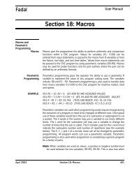
1.1.8 VMC 6535<br />
SIDE VIEW FRONT VIEW<br />
TOP VIEW - BASE<br />
SCALE 2:1<br />
<br />
Figure 1-8: VMC 6535<br />
TOP VIEW<br />
NOTE<br />
Dimensions represented in inches & [millimeters].<br />
16 SPECIFICATIONS MAN-0121 R1
Table 1-8: VMC 6535 Specifications<br />
*Rated Peak Value<br />
<strong>FANUC</strong> MAINTENANCE MANUAL<br />
6535 SPECIFICATIONS 6535 STANDARD 6535 METRIC<br />
Table Size 74.8" x 26.5" 1,899mm x 673.1mm<br />
Floor to Table 40.3" 1024mm<br />
T-Slots (No. x Width x Span) 5 x .709" x 4.92" 5 x 18mm x 125mm<br />
Cutting Feed Rate .01-400 ipm (600 ipm @ 150%) .25-10,160 (15,240 at 150%)<br />
Rapid Feed Rate (X/Y/Z) 900 ipm (X/Y) 700 ipm (Z) 30.5(X,Y) 17.8(Z) m/min<br />
Max. Weight on Table 4,250 lbs. 1,928 kg.<br />
Axis Drive Motor (X/Y/Z) AC 3,800 lbs peak thrust AC, 16,903 N*thrust.<br />
Ball Screw Size 62.2mm Dia. (X/Y/Z)<br />
Longitudinal (X Axis) 65" 1,651mm<br />
Cross (Y Axis) 35" 889mm<br />
Vertical (Z Axis) 34" 864mm<br />
Spindle Nose to Table 5"-39" 127mm-991mm<br />
Spindle Center to Column Ways 37.4" 950mm<br />
Main Motor - Automatic 2 Speed Vector 22.5 HP*, 16.8 KW<br />
Opt. HT Motor - Automatic 2 Speed Vector 30 HP*, 22.4 KW<br />
Torque 220 ft-lbs, 270 ft-lbs (Opt.) 300 Nm/375Nm<br />
Accuracy, Axis Positioning ± .00016" ±.004mm<br />
Accuracy, Axis Repeatability ± .00006" ±.0015mm<br />
Glass Scales (X/Y/Z) Optional<br />
Spindle Speed 10-10,000 rpm (15,000 Opt.),(7,500, 50 tpr.Opt.)<br />
Spindle Orientation Electromechanical<br />
Spindle Taper No. 40 (50 Opt.)<br />
ATC, Number of <strong>Tools</strong> 1.9 sec dual arm / 24 tools (32, 50 tpr. Opt.)<br />
ATC, Tool Selection Random, Bi-directional<br />
Max. Tool Diameter Ø9.85” Ø250mm<br />
Max. Tool Length 15.75" 400mm<br />
Max. Tool Weight 40 lbs. 18 kg<br />
<strong>Machine</strong> Width and Depth 219" W x130" D 5.56m W x 3.3m D<br />
<strong>Machine</strong> Maximum Height 133" 3.4m<br />
<strong>Machine</strong> Weight 29,000 lbs. 6,169 kg<br />
Air Pressure Reqs. (Momentary) 120 psi, 15 scfm 5.5 Bar<br />
Power Reqs. (3-phase) 40/60 amps, 230 VAC (20/25 amps, 480 VAC)<br />
Power Reqs. (3-phase) 50 taper 70 amps, 480 VAC<br />
Cool Power System Spindle, Ballscrews<br />
Ball Screw Supports (X/Y/Z) dual<br />
No. of Ground Boxways per Axis (X/Y/Z) 2<br />
AUGUST 2005 SPECIFICATIONS 17
FADAL MACHINING CENTERS<br />
1.2 FADAL BOLT<br />
TORQUE<br />
SPECIFICATIONS<br />
Table 1-9: Fadal Bolt Torque Specifications<br />
COMPONENT MODEL LOCATION BOLT SIZE TORQUE UNIT<br />
COLUMN ALL COLUMN TO BASE 5/8"-11 X X.50 HHB 175 FT-LBS<br />
COLUMN ALL COUPLER SET SCREW 1/4"-20 X 0.50 SHSS 70 IN-LBS<br />
COLUMN ALL Z B/S MOUNT IN BACK 3/8"-16 X X.XX HHB 45 FT-LBS<br />
COLUMN ALL Z B/S MOUNT IN FRONT 1/2"-13 X 2.XX HHB 75 FT-LBS<br />
COLUMN ALL Z B/S NUT 5/16"-18 X 1.25 HHB 30 FT-LBS<br />
COLUMN ALL Z MOTOR 3/8"-16 X 1.25 SHCS 40 FT-LBS<br />
COLUMN ALL Z XT B/S BEARING MOUNT 5/16"-18 X 1.50 HHB 25 FT-LBS<br />
COLUMN ALL Z XT B/S BEARING SUPPORT (60/8030) 3/8"-18 X X.XX HHB 40 FT-LBS<br />
COLUMN ALL Z XT B/S SUPPORT ADAPTER 5/16"-18 X 1.50 SHCS 15 FT-LBS<br />
HEAD ALL SPINDLE 3/8"-16 X 1.00 SHCS 45 FT-LBS<br />
HEAD ALL SPINDLE RETAINING RING 3/8"-16 X 1.00 HHB 25 FT-LBS<br />
HEAD 7.5K RPM DRAWBAR PISTON 1/4"-20 X 2.00 HHB 15 FT-LBS<br />
HEAD 7.5K RPM ORIENTATION BRID<strong>GE</strong> (7.5K) 3/8"-16 X 6.00 SHCS 45 FT-LBS<br />
HEAD 10K RPM BACK BELT GUIDE 1/2"-13 X 4.00 HHB 70 FT-LBS<br />
HEAD 10K RPM HYDRAULIC PISTON 1/4"-20 X 2.00 HHB 15 FT-LBS<br />
HEAD 10K RPM ORIENTATION BRID<strong>GE</strong> (10K) 5/16"-18 X 6.00 HHB 30 FT-LBS<br />
HEAD 10K RPM SPINDLE MOTOR 1/2"-13 X X.XX HHB 65 FT-LBS<br />
HEAD 10K RPM SPINDLE MOTOR MOUNT 1/2"-13 X X.XX SHCS 70 FT-LBS<br />
HEAD 10K RPM VIBRATION MOUNTS 1/2"-13 X 0.75 SHCS 70 FT-LBS<br />
HEAD 10K RPM Z STRAP 3/8"-16 X 1.75 HHB 45 FT-LBS<br />
X-Y AXIS ALL SADDLE STRAP 3/8"-16 X 1.75 HHB 45 FT-LBS<br />
X-Y AXIS ALL TABLE STRAP 3/8"-16 X 0.75 HHB 45 FT-LBS<br />
X-Y AXIS ALL X B/S NUT 5/16"-18 X 1.XX HHB 25 FT-LBS<br />
X-Y AXIS ALL X-Y MOTOR 3/8"-16 X 1.XX SHSC 40 FT-LBS<br />
X-Y AXIS ALL Y B/S NUT 5/16"-18 X 1.XX SHCS 30 FT-LBS<br />
X-Y AXIS 60/8030 TABLE B/S BLOCK MOUNT (60/8030) 3/8"-16 X 3.50 SHCS 40 FT-LBS<br />
X-Y AXIS 60/8030 X B/S SUPPORT MOUNT (60/8030) 1/2"-13 X 4.50 HHB 80 FT-LBS<br />
X-Y AXIS 60/8030 X MOTOR MOUNT (60/8030) 1/2"-13 X 3.50 HHB 80 FT-LBS<br />
X-Y AXIS 60/8030 Y MOTOR MOUNT (60/8030) 3/8"-16 X 1.50 HHB 40 FT-LBS<br />
X-Y AXIS 22/30/4020 TABLE B/S BLOCK MOUNT (22/3016) 5/16"-18 X 2.75 SHCS 25 FT-LBS<br />
X-Y AXIS 22/30/4020 X B/S SUPPORT MOUNT (22/30/4020) 3/8"-16 X 1.75 HHB 40 FT-LBS<br />
X-Y AXIS 22/30/4020 X-Y MOTOR MOUNT (22/30/4020) 1/2"-13 X 3.XX HHB 80 FT-LBS<br />
18 SPECIFICATIONS MAN-0121 R1
1.2.1 2216 & 3016<br />
TABLE<br />
A<br />
Figure 1-9: 2216 & 3016 Table<br />
<strong>FANUC</strong> MAINTENANCE MANUAL<br />
AUGUST 2005 SPECIFICATIONS 19<br />
B<br />
C<br />
Table 1-10: 2216 & 3016 Table Dimensions<br />
VMCS 2216 & 3016<br />
A 16.00" (406.4 mm)<br />
B 40.50" (1028.7 mm)<br />
C 36.00" (914.4 mm)<br />
D 3.67" (93.22 mm)<br />
E 4.33" (109.98 mm)<br />
D<br />
E<br />
E<br />
D
FADAL MACHINING CENTERS<br />
1.2.2 3020 & 4525<br />
TABLE<br />
A<br />
Figure 1-10: 3020 & 4525 Table<br />
20 SPECIFICATIONS MAN-0121 R1<br />
B<br />
C<br />
Table 1-11: 3020 & 4525 Table Dimensions<br />
VMC 3020 VMC 4525<br />
A 20.00” (508 mm) A 25.00” (635 mm)<br />
B 41.75” (1060.45 mm) B 54.76” (1390.90 mm)<br />
C 36.00” (914.40 mm) C 49.00” (1244.60 mm)<br />
D 2.874” (730 mm) D 3.0125” (76.51 mm)<br />
E 3.74” (95 mm) E 4.921” (124.99 mm)<br />
F 2.1655” (55 mm) F 2.3035” (58.51 mm)<br />
D<br />
E<br />
E<br />
E<br />
E<br />
F
1.2.3 4020 TABLE<br />
A<br />
Figure 1-11: 4020 Table<br />
<strong>FANUC</strong> MAINTENANCE MANUAL<br />
AUGUST 2005 SPECIFICATIONS 21<br />
B<br />
C<br />
Table 1-12: 4020 Table Dimensions<br />
VMC 4020<br />
A 20.00” (508 mm)<br />
B 49.00” (1244.66 mm)<br />
C 43.50” (1104.9 mm)<br />
D 2.52” (64 mm)<br />
E 3.740” (95 mm)<br />
D<br />
E<br />
E<br />
E<br />
E<br />
D
FADAL MACHINING CENTERS<br />
1.2.4 6030 TABLE<br />
A<br />
Figure 1-12: 6030 TABLE<br />
22 SPECIFICATIONS MAN-0121 R1<br />
B<br />
C<br />
Table 1-13: 6030 Table Dimensions<br />
VMC 6030<br />
A 30.00” (762 mm)<br />
B 63.50” (1612.9 mm)<br />
C 58.00” (1473.2 mm)<br />
D 3.976” (101 mm)<br />
E 5.512” (140 mm)<br />
D<br />
E<br />
E<br />
E<br />
E<br />
D
1.2.5 8030 TABLE<br />
A<br />
Figure 1-13: 8030 Table<br />
<strong>FANUC</strong> MAINTENANCE MANUAL<br />
AUGUST 2005 SPECIFICATIONS 23<br />
B<br />
C<br />
Table 1-14: 8030 Table Dimensions<br />
VMC 8030<br />
A 30.00” (762 mm)<br />
B 83.50” (1612.9 mm)<br />
C 78.00” (1473.2 mm)<br />
D 3.976” (101 mm)<br />
E 5.512” (140 mm)<br />
D<br />
E<br />
E<br />
E<br />
E<br />
D
FADAL MACHINING CENTERS<br />
1.2.6 6535 TABLE<br />
A<br />
Figure 1-14: 6535 Table<br />
24 SPECIFICATIONS MAN-0121 R1<br />
B<br />
C<br />
Table 1-15: 6535 Table Dimensions<br />
VMC 6535<br />
A 35.00” (889 mm)<br />
B 74.76” (1899 mm)<br />
C 69.50” (1765 mm)<br />
D 2.74” (70 mm)<br />
E 4.92” (125 mm)<br />
D<br />
E<br />
E<br />
E<br />
E<br />
D
1.2.7 T-SLOTS FOR<br />
ALL TABLES<br />
Figure 1-15: T-Slots for All Tables<br />
<strong>FANUC</strong> MAINTENANCE MANUAL<br />
Table 1-16: Metric T-Slot Dimensions for All Tables<br />
T-SLOT DIMENSIONS<br />
E 0.7086” - 0.7093 ” (17.998 mm - 18.016 mm)<br />
F 1.190” - 1.250” (30.22 mm - 31.75 mm)<br />
G 0.482” - 0.542” (12.24 mm - 13.77 mm)<br />
H 1.299” (32.99 mm)<br />
AUGUST 2005 SPECIFICATIONS 25<br />
E<br />
F<br />
G<br />
METRIC<br />
H
FADAL MACHINING CENTERS<br />
1.3 RECOMMENDED<br />
MAINLINE FUSES /<br />
CIRCUIT BREAKERS<br />
SPINDLE<br />
TYPE<br />
208 V<br />
3 PHASE<br />
Table 1-17: Circuit Breakers for the New Sheet Metal<br />
240 V<br />
3 PHASE<br />
380-415 V<br />
3 PHASE<br />
480 V<br />
3 PHASE<br />
240 V<br />
SINGLE PHASE<br />
5 HP 30A 30A 30A 30A 50A<br />
10 HP 50A 50A 35A 25A 70A<br />
HT 70A 70A 35A 35A 90A<br />
VHT N/A 90A 70A N/A N/A<br />
50 Taper N/A N/A 70A 70 A N/A<br />
SPINDLE<br />
TYPE<br />
208 V<br />
3 PHASE<br />
Table 1-18: Electrical Service Circuit Breaker<br />
240 V<br />
3 PHASE<br />
380-415 V<br />
3 PHASE<br />
480 V<br />
3 PHASE<br />
240 V<br />
SINGLE PHASE<br />
5 HP 30 A 30 A 30 A 30 A 50 A<br />
10 HP 50 A 40 A 25 A 25 A 60 A<br />
HT 70 A 45 A 35 A 25 A 60 A<br />
VHT N/A 90 A 70 A N/A N/A<br />
50-Taper N/A N/A 70 A 70 A N/A<br />
<br />
NOTE<br />
VHT with Fadal control runs only on 220-240V. External transformer required for any other voltage.<br />
VHT with Siemens Control only runs on 400V. External transformer required for any other voltage.<br />
26 SPECIFICATIONS MAN-0121 R1
<strong>FANUC</strong> MAINTENANCE MANUAL<br />
2.0 PRE-INSTALLATION PROCEDURES<br />
AUGUST 2005 PRE-INSTALLATION PROCEDURES 27
FADAL MACHINING CENTERS<br />
<br />
2.1 FOUNDATION WARNING!<br />
The VMC MUST be placed on a surface that will support the combined weight of<br />
the VMC, options, fixtures, and tooling, etc. (refer to the VMC Specifications section<br />
at the beginning of this manual for VMC weights).<br />
1. It is recommended that most models be placed on a isolated concrete pad 8-12”<br />
thick. For VMC 6030 and larger the foundation pad should be 12-15”. (Figure 2-1:,<br />
Dimension C). For A and B dimensions, see Table 2-1:Isolation Pad Dimensions.<br />
A<br />
#4 REBAR<br />
AS SHOWN<br />
Figure 2-1: Typical Pad Construction<br />
5/8 FELT<br />
5/8 FELT<br />
CAULK SEAMS TO<br />
SEAL FLOOR TYP.<br />
2. The VMC should be positioned on a single slab. Placing the VMC over an<br />
expansion joint may cause the VMC to shift when each individual slab moves.<br />
3. The surface below the leveling pads should be free from cracks. Placing the VMC<br />
over a crack may cause the VMC to shift during use. Inadequate flooring could<br />
result in mechanical degradation.<br />
4. Bolt the VMC directly to the pad through the .953” diameter holes that are provided<br />
in the base casting. The dimensions for the base mounting holes of all machines<br />
are in the VMC Specifications section (See Specifications, Section 1.0, MAN-0121<br />
R1). Anchors are to be installed as shown below (Figure 2-2: Anchor Stud<br />
28 PRE-INSTALLATION PROCEDURES MAN-0121 R1<br />
B<br />
C
<strong>FANUC</strong> MAINTENANCE MANUAL<br />
Installation). For high performance machines, the machine must be bolted to<br />
achieve maximum performance.<br />
Figure 2-2: Anchor Stud Installation<br />
Anchor stud installation:<br />
1. Wear safety goggles.<br />
Table 2-1: Isolation Pad Dimensions<br />
MACHINE A (DEPTH) B (WIDTH)<br />
2216/ 3016 7ft 9in 9ft 6in<br />
4020 8ft 7in 11ft<br />
3020 8ft 5in 10ft 2in<br />
4525 8ft 10in 12ft<br />
6030 9ft 11in 14ft 6in<br />
6535 9ft 11in 15ft 10in<br />
8030 9ft 11in 18ft 9in<br />
2. Use 7/8 carbide tipped drill for the anchor you are using.<br />
3. Use a rotary-hammer drill and drill the base material to depth.<br />
AUGUST 2005 PRE-INSTALLATION PROCEDURES 29
FADAL MACHINING CENTERS<br />
4. Use proper eye and hearing protection while performing this step. Remove<br />
dust and rubble from the hole with compressed air and brush.<br />
5. Insert capsule in the hole, either end first.<br />
6. Select proper 1/2” SQ. drive socket and attach to sup-r-setter.<br />
7. Jam nut on stud as per illustration.<br />
8. Using a 1 1/8” socket insert the stud into the hole to break the capsule.<br />
9. Under rotary power, push the stud to full depth, maintaining power for two or three<br />
seconds after the stud bottoms.<br />
10. Promptly and carefully release the installation tool from the stud, leaving it<br />
undisturbed right through the prescribed curing time consistent with on-site<br />
temperature.<br />
11. Install machine.<br />
12. Level machine.<br />
13. Add two flat washers, one lock washer and one nut per threaded rod.<br />
14. Tighten nut, stop when washer gets flat, do not overtighten.<br />
15. Recheck level.<br />
Recommended curing time<br />
58ºF to 68ºF 30 MIN<br />
50ºF to 58ºF 1 HR<br />
41ºF to 50ºF 2 HRs<br />
32ºF to 41ºF 4 HRs<br />
23ºF to 32ºF 8 HRs<br />
14ºF to 23ºF 24 HRs<br />
Ground should be compacted to 90%. A layer of 3/4” (1”nominal) crushed rock can be<br />
applied at 6” thickness for added support.<br />
For rebar in all pads, use #4 rebar 18” on center, three inches off the ground.<br />
For vibration dampening, 5/8 or thicker felt on all sides is sufficient. If the customer<br />
wants to have a larger pad to support several machines, the pads should be 10-12” or<br />
30 PRE-INSTALLATION PROCEDURES MAN-0121 R1
thicker with # 4 rebar 18” on center three inches off the ground.<br />
<strong>FANUC</strong> MAINTENANCE MANUAL<br />
For stress lines in the concrete make sure they are such that they do not go under any<br />
of the machines. (If they do, this will eventually defeat the purpose of the pad.)<br />
The top of the felt, if used, should be sealed with a caulking compound to prevent oils<br />
and coolants from penetrating the ground. (Compound must be resistant to oils and<br />
coolants of course). A recommended product is Volcum.<br />
Concrete to use for the pad should be rated at least 3000 psi. It should also contain 3/4”<br />
(1” nominal) crushed rock. Curing time should be at least 7 days. The longer foundation<br />
is allowed to cure, the better. If accelerants are used to cure the concrete in less time,<br />
cracking is more likely to occur.<br />
AUGUST 2005 PRE-INSTALLATION PROCEDURES 31
FADAL MACHINING CENTERS<br />
2.2 SHIPPING<br />
DIMENSIONS<br />
<br />
Table 2-2: VMC Shipping Dimensions<br />
VMC LENGTH WIDTH HEIGHT WEIGHT Z MTR DWN<br />
8030 17ft 8in 8ft 8in 10ft 2in 19,000lbs 8ft 8in<br />
6535 14ft 9in 8ft 10in 11ft 3in 30,000lbs 11ft 3in<br />
6030 13ft 2in 8ft 8in 10ft 2in 17,000lbs 8ft 8in<br />
4525 8ft 10in 7ft 10in 10ft 13,600lbs 8ft 5in<br />
4020 9ft 7in 7ft 8ft 3in 10,500lbs 6ft 8in<br />
4020 9ft 7in 7ft 9ft 1in ext column<br />
10,500lbs 7ft 5in<br />
3020 8ft 10in 6ft 10in 10ft 12,400lbs 8ft 5in<br />
3016 8ft 3in 6ft 5in 8ft 2in 9,500lbs 6ft 8in<br />
3016 8ft 3in 6ft 5in 8ft 8in ext column<br />
9,500lbs 7ft 4in<br />
2216 8ft 3in 6ft 5in 8ft 2in 9,100lbs 6ft 8in<br />
2216 8ft 3in 6ft 5in 8ft 8in ext column<br />
9,100lbs 7ft 4in<br />
HYDRO 8ft 5in 4ft 2in 5ft 3in 820lbs<br />
PALLET 7ft 2in 3ft 3in 3ft 8in 911lbs<br />
Table 2-3: VMC Crated Dimensions & Weights<br />
VMC LENGTH WIDTH HEIGHT WEIGHT<br />
8030 17ft 8in 8ft 8in 10ft 2in 20,500lbs est<br />
6535 20ft 10ft 4in 14ft 4in 35,000lbs est<br />
6030 14ft 8ft 8in 10ft 2in 18,500lbs est<br />
4525 10ft 5in 8ft 8ft 7in 16,000lbs est<br />
4020 10ft 5in 8ft 8ft 7in 11,800lbs est<br />
3020 9ft 8ft 8ft 7in 13,000lbs est<br />
3016 9ft 7ft 8ft 7in 10,300lbs est<br />
2216 9ft 7ft 8ft 7in 10,300lbs est<br />
HYDRO 9ft 3in 4ft 9in 6ft 1,420lbs est<br />
PALLET 7ft 9in 4ft 9in 6ft 1,411lbs est<br />
NOTE<br />
All VMCs 6535 and 8030 do not get crated. (Unless specified by customer or distributor.) They are<br />
placed on pallets and vacuum sealed.<br />
32 PRE-INSTALLATION PROCEDURES MAN-0121 R1
<strong>FANUC</strong> MAINTENANCE MANUAL<br />
2.3 POSITIONING 1. Place the VMC so that skylights or air vents are NOT directly overhead. Do not<br />
expose the machine to direct sunlight, or any other heat source. Do not place the<br />
machine in an area that will expose the machine to moisture, standing water, liquid<br />
or rain.<br />
2. Ensure there is adequate room behind the VMC to fully open the rear cabinet door.<br />
Minimum clearance behind the machine is two feet (24”/ 60.96 cm.)<br />
Figure 2-3: 24” Minimum Clearance Behind VMC<br />
3. Ensure adequate ceiling clearance for the Z axis conduit with the Z axis in the<br />
Z+4.0” (10.16cm) position. VMCs with the Extended Travel option require an<br />
additional 8.0” (20.32cm) vertical clearance.<br />
Regular Column (Z+4.0”<br />
(0.35m))<br />
Extended Column 28.0”<br />
(0.7m)<br />
Table 2-4: Minimum Ceiling Clearances (inches/metric)<br />
VMC<br />
2216,<br />
3016<br />
97.00”<br />
2.56m<br />
105.00”<br />
2.67m<br />
98.00”<br />
2.5m<br />
VMC<br />
4020<br />
106.00”<br />
2.7m<br />
VMC<br />
6030,<br />
8030<br />
126.00”<br />
3.2m<br />
VMC<br />
3020,<br />
4525<br />
127.00”<br />
3.22m<br />
N/A 135.00”<br />
3.43m<br />
AUGUST 2005 PRE-INSTALLATION PROCEDURES 33<br />
VMC<br />
6535<br />
140.00”<br />
3.55m<br />
N/A
FADAL MACHINING CENTERS<br />
<br />
2.4 AIR SUPPLY WARNING!<br />
Air pressure required: 120psi before regulator, 80 psi after regulator, 15 scfm (standard<br />
cubic feet per minute) momentary.<br />
1. From the main air supply line attach a 3/8” air supply line for the VMC. The distance<br />
from the air compressor and number of machines attached should be taken into<br />
consideration when determining the size of piping for the main air supply line.<br />
2. Piping may consist of one or more of the following: galvanized pipe, PVC pipe or<br />
high pressure hose. Do not use quick disconnects; quick disconnects will restrict air<br />
flow.<br />
3. A “T” riser should be used to connect the main air supply line with the air supply line<br />
to the VMC (See Figure 2-4: Attach Drain to Lowest Point of Air Supply Line).<br />
4. To prevent moisture from entering the VMC’s air system, attach a drain to the<br />
lowest point of the air supply line. (See Figure 2-4: Attach Drain to Lowest Point of<br />
Air Supply Line). The drain could be a self-relieving moisture separator, a simple<br />
petcock, or a gate valve opened occasionally to release the water build-up. An air<br />
dryer is preferred where higher moisture levels exist.<br />
5. To help prevent contaminants from entering the air system on the VMC, place a<br />
filter in-line on the main air supply line.<br />
Figure 2-4: Attach Drain to Lowest Point of Air Supply Line<br />
34 PRE-INSTALLATION PROCEDURES MAN-0121 R1
2.5 ELECTRICAL<br />
GROUNDING<br />
2.5.1 PRIMARY<br />
GROUNDING<br />
2.5.2 SUPPLEMENTAL<br />
GROUNDING<br />
<br />
<strong>FANUC</strong> MAINTENANCE MANUAL<br />
WARNING!<br />
The importance of proper grounding CANNOT be over-emphasized! Improper<br />
grounding will result in a wide range of hard-to-diagnose problems in communications,<br />
positioning, spindle motion, etc.<br />
1. The grounding conductor shall be of copper. The material selected shall be<br />
resistant to any corrosive condition existing at the installation or shall be suitably<br />
protected against corrosion.<br />
2. The grounding conductor shall be a No. 8 AWG (10 mm 2 ) or larger equipment<br />
ground conductor, and must be:<br />
• solid or stranded<br />
• insulated, covered, or bare<br />
• installed in one continuous length without a splice or joint.<br />
3. Individually covered or insulated grounding conductors shall have a continuous<br />
outer finish that is either green, or green with one or more yellow stripes.<br />
4. A No. 8 AWG (10 mm 2 ) or larger equipment ground conductor and 3 phase<br />
conductors must be contained within one of the following:<br />
• rigid metal conduit<br />
• intermediate metal conduit<br />
• electrical metallic tubing<br />
5. The ground conductor shall be connected between the VMC’s ground bus and the<br />
approved ground bus contained within the voltage supply panel board or enclosure.<br />
6. The VMC branch supply conduit, phase conductors and ground conductors must<br />
be dedicated to a single VMC. They cannot be used to supply any other loads.<br />
1. Supplementary grounding electrodes shall be permitted to augment the equipment<br />
grounding conductor; however, the earth shall not be used as the sole equipment<br />
grounding conductor.<br />
2. The supplemental grounding conductor shall be a No. 6 (16 mm 2 ) or larger copper<br />
conductor in the form of a wire, and must be:<br />
• solid or stranded<br />
• insulated, covered or bare<br />
• installed in one continuous length without splice or joint<br />
3. A No. 6 (16 mm 2 ) or larger grounding conductor shall be run in one of the following:<br />
• rigid metal conduit<br />
AUGUST 2005 PRE-INSTALLATION PROCEDURES 35
FADAL MACHINING CENTERS<br />
<br />
• intermediate metal conduit<br />
• electrical metallic tubing or cable armor<br />
4. One end of the supplemental grounding conductor shall be attached to the VMC’s<br />
ground bus. The other end shall be effectively bonded to a copper cold water pipe<br />
that is in direct contact with the earth for 10 feet or more (See Figure 2-5: Bond<br />
Grounding Conductor to Copper Cold Water Pipe).<br />
5. Connections shall be made so that they are electrically continuous.<br />
Figure 2-5: Bond Grounding Conductor to Copper Cold Water Pipe<br />
WARNING!<br />
Many problems that are difficult to diagnose can occur if the VMC is not properly<br />
grounded. Proper grounding cannot be overemphasized.<br />
36 PRE-INSTALLATION PROCEDURES MAN-0121 R1
2.6 CHECKING<br />
GROUNDING<br />
INTEGRITY OF FADAL<br />
VMCS<br />
2.6.1 SPECIFICATION -<br />
GROUNDING FOR THE<br />
FADAL MACHINE<br />
2.6.2 INSPECTION -<br />
CHECK GROUND<br />
WIRE COMING INTO<br />
VMC<br />
2.6.3 VERIFICATION -<br />
CHECK GROUNDING<br />
INTEGRITY WITH<br />
FLUKE METER<br />
<strong>FANUC</strong> MAINTENANCE MANUAL<br />
1. MUST conferm to NEC code as stated in the Maintenance Manual.<br />
2. MUST be a continuous wire 8 AWG or larger between the VMC's ground bus and<br />
the building power distribution panel serving the VMC.<br />
3. MUST be dedicated to a single VMC. (The ground and phase conductors cannot<br />
be shared with any other equipment.)<br />
4. Ground rods and other supplemental grounding may be used in addition to the<br />
ground specified above but not instead of it.<br />
1. The ground wire coming into the VMC and going to the building power distribution<br />
panel must be 8AWG or larger.<br />
2. The ground wire must be connected to the ground bar in the back cabinet of the<br />
VMC. (It does not go to a screw in the disconnect box.)<br />
3. The ground wire is to be a continuous wire from the VMC to the building power<br />
distribution panel serving the VMC. The conduit is not to be used as the grounding<br />
conductor. Ground rods and other supplemental grounding may be used in addition<br />
to the ground specified above but not instead of it. Servicemen are not the<br />
appropriate people to be inspecting power distribution panels or building wiring.<br />
The serviceman is not expected to physically verify the routing of the ground<br />
conductor, but should look for any indications that grounding is not as specified.<br />
1. Measure the resistance (ohms) of a length of 16AWG or larger wire that is long<br />
enough to reach from the VMC to the building power distribution panel that supplies<br />
the VMC. Record reading.<br />
2. Attach the wire of step 1 (test wire) to the ground bus of VMC. The other end will be<br />
used for measurement at the power distribution enclosure. (Do not open the<br />
enclosure. Use a bare screw or bare metal on the enclosure for measurements.)<br />
3. Set meter to AC Volts; with VMC on, measure and record voltage between the test<br />
wire and the power distribution enclosure. Set meter to DC Volts; measure and<br />
record voltage. Voltages should be OV with machine on but not operating, (up to<br />
.O1OV is OK).<br />
AUGUST 2005 PRE-INSTALLATION PROCEDURES 37
FADAL MACHINING CENTERS<br />
2.6.4 ELECTRICAL<br />
SERVICE<br />
2.6.5 PREFERRED<br />
SERVICE<br />
2.6.6 ALTERNATE<br />
SERVICE<br />
<br />
<br />
4. Turn off the VMC and measure the ground voltages (AC and DC) again. Record<br />
these readings. Voltages should be OV to .005V.<br />
5. Voltages (AC or DC) across the ground wire will cause false resistance readings. If<br />
the ground voltages with VMC off are 0 (.005VAC max.), set meter to ohms and<br />
measure resistance between VMC ground bus and power distribution enclosure.<br />
Resistance measurement should be less than twice the resistance measured in<br />
step 1. (If resistance is negative (due to a ground current), reverse meter leads and<br />
average the two readings.)<br />
WARNING!<br />
Electrical installation of machine must be done by a qualified electrician.<br />
1. The total connected load should not exceed 75% of the panel rating, allowing for<br />
the VMC load. Refer to the Electrical Rating Plaque for full load current.<br />
2. If other CNC equipment, motor controllers, motors or electric-discharge lighting<br />
(fluorescent, mercury vapor, metal-halide, high and low pressure sodium) are<br />
connected to the same panel, the connected load should not exceed 50% of the<br />
panels rated capacity.<br />
3. Prior to the installation of the VMC, the panel should be measured for average and<br />
peak loads across the three phases.<br />
WARNING!<br />
The VMC must NOT be installed on a panel where the measured surge demand<br />
current exceeds the panel’s supply amplitude.<br />
The VMC should be supplied by a dedicated circuit connected directly to the Service<br />
Entrance panel.<br />
The VMC may be supplied by a dedicated circuit connected directly to the local branch<br />
panel.<br />
38 PRE-INSTALLATION PROCEDURES MAN-0121 R1
2.6.7 WIRING<br />
<strong>FANUC</strong> MAINTENANCE MANUAL<br />
Table 2-5: Wiring Requirements<br />
40 Taper 240 VAC 3 Ø 8 AWG (10 mm 2 ) stranded<br />
THHN copper within 100 ft.<br />
of panel. For VHT 4AWG<br />
40 Taper 480 VAC 3 Ø 10 AWG (6 mm 2 ) stranded<br />
THHN copper within 100 ft.<br />
of panel. For VHT 6 AWG<br />
40 Taper 240 VAC Single Ø 6 AWG (16 mm 2 ) stranded<br />
THHN copper within 50 ft.<br />
of panel.<br />
50 Taper 480 VAC 3 Ø 4 AWG (25 mm2 ) stranded<br />
THHN copper within 100 ft.<br />
of panel.<br />
50 Taper 240 VAC 3 Ø 1AWG (50 mm2 ) stranded<br />
THHN copper within 100 ft.<br />
of panel.<br />
6 AWG (16 mm 2 ) stranded THHN<br />
copper 100 ft. or more from panel.<br />
For VHT 3 AWG<br />
8 AWG (10 mm 2 ) stranded THHN<br />
copper 100 ft. or more from panel.<br />
For VHT 4 AWG<br />
4 AWG (25 mm 2 ) stranded THHN<br />
copper from 50 to 100 ft. from<br />
panel.<br />
3 AWG (30 mm 2 ) stranded THHN<br />
copper 100 ft. or more from panel.<br />
1/0 AWG (60 mm 2 ) stranded<br />
THHN copper 100 ft. or more<br />
from panel.<br />
AUGUST 2005 PRE-INSTALLATION PROCEDURES 39
FADAL MACHINING CENTERS<br />
2.6.8 CONDUIT 1. The number and size of conductors in any raceway shall not be more than will<br />
permit dissipation of the heat.<br />
2. The conduit must allow ready installation or withdrawal of the conductors without<br />
damage to the conductors or to their insulation.<br />
# OF<br />
CONDUCTORS<br />
Table 2-6: Conduit Selection<br />
CONDUCTOR SIZE MINIMUM SIZE OF<br />
CONDUIT<br />
4 10 AWG THHN (6 mm 2 ) 1/2”<br />
4 8 AWG THHN (10 mm 2 ) 3/4”<br />
4 6 AWG THHN (16 mm 2 ) 3/4”<br />
3 4 AWG THHN (25 mm2 ) 1.0”<br />
40 PRE-INSTALLATION PROCEDURES MAN-0121 R1
<strong>FANUC</strong> MAINTENANCE MANUAL<br />
3.0 INSTALLATION PROCEDURE<br />
WARNING!<br />
Before beginning the <strong>Machine</strong> Installation & Hook-Up it is important to review the<br />
entire Installation Procedure section.<br />
AUGUST 2005 INSTALLATION PROCEDURE 41
FADAL MACHINING CENTERS<br />
3.1 MACHINE<br />
INSTALLATION &<br />
HOOK-UP<br />
3.1.1 UNPACKING <strong>Tools</strong> Required<br />
3.1.2 PLACING THE<br />
VMC<br />
<br />
Hammer, 15/16” socket or wrench and knife<br />
1. Remove the crate and/or protective material from around the VMC.<br />
2. Remove the strapping material from the front doors.<br />
3. Unload the boxes from the inside and/or around the VMC.<br />
4. Remove each of the four 5/8” bolts and nuts between the base of the VMC and the<br />
pallet.<br />
1. Place the leveling pads (countersink side up) under the leveling bolts. Be sure<br />
leveling bolts go into countersink on leveling pads.<br />
NOTE<br />
Use leveling pad SHP-0002 (PLC-0063 for slant sheet metal machines, or machines equipped with<br />
the HydroSweep option) for placing the machine. Any other pad may cause damage to the machine.<br />
2. Remove the fork lift bars or the eye bolts and the steel bar from the column.<br />
42 INSTALLATION PROCEDURE MAN-0121 R1
3. At this point the VMC is ready for power and air connections.<br />
Figure 3-1: Placing the VMC<br />
3.1.3 AIR SUPPLY WARNING!<br />
Hole procided for 1-1/4” bar<br />
minimum bar length 36”<br />
<strong>FANUC</strong> MAINTENANCE MANUAL<br />
AIR PRESSURE REQUIRED: 120 psi before regulator, 80 psi after regulator, 15<br />
scfm (standard cubic feet per minute) momentary.<br />
1. Connect the 3/8” air hose to the VMC.<br />
1-8”eye bolt 2 places<br />
1.5” eye bolt 2 places for 6535<br />
Maximum fork width is 6.00”<br />
AUGUST 2005 INSTALLATION PROCEDURE 43
FADAL MACHINING CENTERS<br />
<br />
3.1.4 POWER CHECK WARNING!<br />
2. Check the pressure gauge for 120 psi and adjust the regulator on the VMC if<br />
necessary.<br />
3. Check for air leaks at the fitting and around the air regulator.<br />
4. It is important that the air compressor turns on when the pressure drops to<br />
approximately 120 psi. This assures the VMC a constant 80 psi.<br />
Do NOT power on the VMC before completing this section.<br />
<strong>Tools</strong> Required<br />
Fluke DMM, screwdriver or Wago tool 210-141<br />
(ST-26), 5/16” hex bit socket and 3/4” open or box wrench.<br />
Verify the Main Power Fuses<br />
With the main disconnect switch in the off (down) position, open the cover to the main<br />
disconnect box.<br />
44 INSTALLATION PROCEDURE MAN-0121 R1
Verify the MOV Surge Suppressor Board<br />
<strong>FANUC</strong> MAINTENANCE MANUAL<br />
1. Locate the MOV Surge Suppressor Board (see Figure 3-2: MOV Surge Suppressor<br />
Board).<br />
Figure 3-2: MOV Surge Suppressor Board<br />
2. Find the part number on the board.<br />
a. If your incoming voltage is under 250 VAC, then an 1170-2 (PCB-0145) should<br />
be installed.<br />
b. If your incoming voltage is over 250 VAC, then an 1170-2 (PCB-0146) should<br />
be installed.<br />
3. Identify the jumper and AC input locations. Use Figure 3-3 through 3-5 for three<br />
phase and single phase transformers.<br />
a. Where are the jumpers located?<br />
b. Where are the AC inputs (L1, L2, L3) located?<br />
4. With the jumper and AC input locations, locate the voltage setting of the<br />
transformer using the table in either (3 phase) or (single phase).<br />
Jumper (Step 6a) AC Input (Step 6b) = Voltage Setting<br />
3-6 8 = 240VAC<br />
AUGUST 2005 INSTALLATION PROCEDURE 45
FADAL MACHINING CENTERS<br />
Figure 3-3:<br />
Figure 3-4:<br />
46 INSTALLATION PROCEDURE MAN-0121 R1
Figure 3-5:<br />
The VMC is Ready for the Initial Power on Procedure<br />
1. Move the main disconnect switch to the ON (up) position.<br />
<strong>FANUC</strong> MAINTENANCE MANUAL<br />
2. Measure the voltage at the transformers secondary between A12-B12, A12-C12,<br />
B12-C12.<br />
3. For single phase measure across A8-C8. The voltage should be between 230-240<br />
VAC, correct if necessary.<br />
4. Push the EMER<strong>GE</strong>NCY STOP switch to disable the axes, then push the CNC<br />
POWER button.<br />
5. Check the voltages on the D.C. power supply, i.e. 5, + 12, -12 VDC.<br />
6. Reset the EMER<strong>GE</strong>NCY STOP switch.<br />
7. Unbolt and remove the support between the table and the head.<br />
8. Unbolt and remove the counterweight bars from the column, located next to the<br />
main disconnect box.<br />
9. Jog the axis to the cold start indicators and cold start the VMC.<br />
AUGUST 2005 INSTALLATION PROCEDURE 47
FADAL MACHINING CENTERS<br />
3.2 TRANSFORMER<br />
TAPPING<br />
<br />
1. With the machine main power switch turned OFF, verify that the chart on the door of<br />
the cabinet is the one for the transformer in the machine.<br />
2. Measure the input voltage to the machine on the chart (Measure leg to leg the input<br />
power lines to the machine.).<br />
3. Next to the voltage on the chart will be a “jumper” number, such as 3-6, and a “AC<br />
Input” number, such as 7.<br />
4. Each phase has a group of terminals such as A3 to A8 for phase 1 and B3 to B8 for<br />
phase 2. Place a jumper between the two terminals listed on the chart for each<br />
phase. Using the same example place jumper from A3 to A6 for phase 1, B3 to B6<br />
for phase 2 and one from C3 to C6 for phase 3.<br />
5. Place the input tap wire in the proper terminal, as in example A7 for phase 1, B7 for<br />
phase 2 and C7 for phase 3.<br />
6. Turn ON the main power switch.<br />
7. Measure the input voltage to the spindle drive, usually labeled L1, L2 & L3, leg to<br />
leg. Should be about 230 VAC with the range being from 220 to 240 VAC. If the<br />
difference between 230 and the measured voltage is greater then ten (10) volts<br />
then power down. If the voltage is too high then select the next higher voltage on<br />
the chart and change the jumper and / or input tap and recheck. If the voltage is too<br />
low then select the next lower voltage and change and check.<br />
NOTE<br />
It is acceptable to have the legs tapped differently by one voltage tap position. There should be no<br />
more than one position.<br />
48 INSTALLATION PROCEDURE MAN-0121 R1
3.3 SINGLE PHASE<br />
INPUT POWER<br />
<strong>FANUC</strong> MAINTENANCE MANUAL<br />
The Fadal VMC line is designed for three phase input power. However, three-phase<br />
power is not always available. If this is the case, Fadal offers a single-phase input<br />
power option. Most Fadal machines are capable of operating on single-phase line input.<br />
The torque ratings will be at 60% of the published performance. The rapid traverse rate<br />
is reduced to not more than 700 IPM for machines with higher speed capability. This is<br />
because as the DC bus capacitors are drained and the bus voltage drops, the singlephase<br />
input can not recharge the capacitors as fast as the three-phase. Lower bus<br />
voltage equals lower speed and more current. Single-phase requires 73% more current<br />
to maintain the same performance (square root of 3). The main limitation is the spindle<br />
drive. It will not draw more than its rated current. The current rise is steeper in singlephase<br />
and will, therefore, trip sooner.<br />
Fadal does not recommend single-phase power for the High torque or the 6535, 6030<br />
and 8030 machines and cannot be used with VHT or 50 taper. This option can be<br />
ordered on a new machine and can be installed in the field. Some wiring changes are<br />
also necessary. Please see the single-phase transformer charts and wiring instructions.<br />
AUGUST 2005 INSTALLATION PROCEDURE 49
FADAL MACHINING CENTERS<br />
3.4 PHASE<br />
CONVERTER ROTARY<br />
The normal Fadal VMC requires three phase-input power. The machines are also<br />
configured in a single-phase power configuration when requested. Some customers<br />
prefer to use rotary phase converters. However, Fadal does not recommend the use of<br />
rotary phase converters.<br />
Rotary phase converters input single-phase 208 to 230 VAC and output three phase<br />
230 VAC. For a VMC close to a 5% voltage balance between legs is desirable, in<br />
reference to the voltage differences of each phase. Most CNC machines would require<br />
the output power to be 1-1/2 to 2 times larger than the spindle motor (for a Fadal output<br />
must be at or higher than the minimum of the required input; see Specifications, Section<br />
1.0, MAN-0121 R1). A Voltage Stabilizer may also be required. The stabilizer’s function<br />
is to maintain a consistent voltage level of the three phases during light or no load<br />
conditions.<br />
50 INSTALLATION PROCEDURE MAN-0121 R1
<strong>FANUC</strong> MAINTENANCE MANUAL<br />
3.5 LEVELING Leveling is an important first step in setting up the VMC. All calibration and squareness<br />
performed on the assembly line is done with the machine leveled. It is important to<br />
follow the sequence below precisely to ensure proper results.<br />
3.5.1 FOR ALL BOX<br />
WAY VMCS<br />
<br />
<br />
<strong>Tools</strong> Required<br />
Precision Level, such as the Starrett 12”, P/N 199Z<br />
WARNING!<br />
Verify that the scale reads the same when rotated 180 degrees.<br />
If using a flashlight to see the bubble, do not place the flashlight on the level, as it<br />
will warm the bubble and give an incorrect reading.<br />
1. The VMC should be positioned on one solid concrete slab (see Pre-Installation,<br />
section 2, MAN-0121 R1). Do not straddle any cracks or seams.<br />
2. Center the leveling pads under the leveling screws.<br />
3. Level the VMC as close as possible to the leveling pads. The leveling screws<br />
should be extended as little as possible to reduce vibration through the sheet<br />
metal.<br />
NOTE<br />
Make sure that machines with the chip conveyor option are raised high enough so that the chip<br />
conveyor tank fits under the sheet metal of the VMC.<br />
4. Verify the Cold Start indicators, then cold start the VMC.<br />
5. Clean the level with alcohol.<br />
6. Jog the Y axis to the Y+ limit.<br />
7. Clean the outer base ways with alcohol.<br />
AUGUST 2005 INSTALLATION PROCEDURE 51
FADAL MACHINING CENTERS<br />
8. Place the level on the right hand way (the outer right hand way on the 6535) of the<br />
base with the small bubble towards the column. Take an accurate reading. (See<br />
Figure 3-6: Leveling Box Way.)<br />
Figure 3-6: Leveling Box Way.<br />
9. Now put the level on the left hand way (the outer left hand way on the 6535) of the<br />
base with the level pointing in the same direction as on the right hand way.<br />
10. Adjust the leveling screws on the machine until the left hand way and the right hand<br />
way level are even.<br />
11. The level will have a front to back bubble and a side to side bubble. Level the<br />
machine from front to back first and then from side to side. When adjusting the side<br />
to side, adjust both leveling screws of one side only.<br />
12. If leveling larger machines, such as the 6535, 6030 or 8030 models, the center four<br />
leveling screws must not be touching the leveling pads during the leveling<br />
procedure. After the machine has been leveled, lower the four screws to the pad,<br />
then check the level and tram readings to ensure they have not changed.<br />
52 INSTALLATION PROCEDURE MAN-0121 R1
<strong>FANUC</strong> MAINTENANCE MANUAL<br />
13. Verify the spindle tram and, if necessary, adjust by slightly changing only the two<br />
front leveling screws.<br />
AUGUST 2005 INSTALLATION PROCEDURE 53
FADAL MACHINING CENTERS<br />
3.6 HOLD DOWN<br />
CLAMPS<br />
Larger machines may vibrate, bump on reversals, and degrade floor finish.<br />
This may indicate that the base casting needs to be clamped to floor.<br />
Larger machines need to be clamped to the floor to prevent movement between the<br />
machine and the floor, and clamping holes are provided on all base castings for this<br />
purpose.<br />
The kit SHP-0116 has been developed to mount the machine to the floor without<br />
moving it.<br />
1. The Clamp is first mounted into the clamping hole in the base.<br />
2. The position is marked on the floor for drilling a ½” hole into the concrete.<br />
3. The RedHead stud is mounted in the floor with one nut and washer on it.<br />
4. The Clamp is mounted over the stud and then the two ½ inch Socket Cap screws<br />
are tightened, pinching the flange of the base casting.<br />
5. The second washer and nut are tightened onto the stud, inhibiting any flexing up or<br />
down of the base casting.<br />
6. Recheck machine level.<br />
Hilti (mfg in Liechtenstein) makes a Right-Angle Hammer Drill, model TE-5, with a<br />
model TE-AC Right Angle Head attachment, that works very well in this application.<br />
54 INSTALLATION PROCEDURE MAN-0121 R1
3.7 OPTICAL FIBER<br />
CABLE HANDLING<br />
Careful handling of Optical Fiber Cable:<br />
<strong>FANUC</strong> MAINTENANCE MANUAL<br />
1. Even though reinforcing cover used on the optical fiber code has enough mechanical<br />
strength, be sure not to be damaged by heavy materials drop.<br />
2. Detaching and attaching of optical connector should always be made by touching<br />
connector. Optical fiber code should not be touched when replacement.<br />
3. Optical connector is automatically locked with upper side lock levels after being<br />
connected. It is impossible to pull out the connector without releasing the lock levels.<br />
4. Optical connector can not be connected oppositely. Be sure the connector direction<br />
when connection is done.<br />
5. Optical connector should be processed as follows before laying of optical fiber<br />
cable.<br />
Fix a reinforcing cover to a wire with hook or tension member by a tape. At<br />
laying hook the wire or pull the tension member taking enough care that optical<br />
connector does not receive pulling strength.<br />
6. Reinforcing cover is fixed to cable lamp so that optical fiber cable could not weight<br />
directly the connecting part of connector.<br />
7. Notice that optical connector’s chip is clear. The attached protect cap must be<br />
always put on when optical connector is not used.<br />
8. Remove dirt with a clear tissue or absorbent cotton (cotton with ethyl alcohol is<br />
applicable). No other organic solvent than ethyl alcohol can be used.<br />
AUGUST 2005 INSTALLATION PROCEDURE 55
FADAL MACHINING CENTERS<br />
3.8 COUPLER<br />
INSTALLATION ON<br />
AXIS MOTOR OR<br />
BALLSCREW<br />
<br />
NOTE<br />
Motor and Ball Screw shaft must be clean and oil free.<br />
Follow the next procedure:<br />
1. Loozen both coupler HUB screws.<br />
2. Mark coupler HUBs and SPIDER before disassembling to insure coupler is assembled<br />
back together the same way.<br />
Figure 3-7: Coupler<br />
3. Separate coupler HUBs.<br />
4. Install bottom coupler HUB on to axis motor shaft.<br />
5. Coupler must be gaged 0.10” (2.54mm) away from axis motor face.<br />
56 INSTALLATION PROCEDURE MAN-0121 R1
<strong>FANUC</strong> MAINTENANCE MANUAL<br />
6. Install the SPIDER and set the tolerance on all 4 RAISED BOSSes to 0.015”-0.030”<br />
from the HUB using 2 (two) 0.015”(0.381mm) and 0.030” (0.762mm) feeler gages.<br />
Figure 3-8: Gages<br />
7. Install Ball Screw coupler HUB on the SPIDER and set the tolerance on all 4<br />
RAISED BOSSes to 0.015 “ - 0.030” (0.381-0.762mm) from the HUB using 2 (two)<br />
0.015” or 0.030” feeler gages and torque coupler HUB to Ball Screw shaft using<br />
correct torque specification.<br />
NOTE<br />
Verify when the coupler assembly is completely installed all 8 RAISED BOSSes must be checked<br />
and set to 0.015” - 0.030”(0.381-0.762mm).<br />
8. Clean marked notes from coupler assembly when installation is complete.<br />
Figure 3-9: Motors<br />
Z-AXIS 8ft<br />
Y-AXIS 8ft<br />
X-AXIS 8ft<br />
AUGUST 2005 INSTALLATION PROCEDURE 57
FADAL MACHINING CENTERS<br />
Figure 3-10: Motors<br />
Table 3-1: Couplers<br />
MACHINE X AXIS Y AXIS Z AXIS<br />
EMC KTR ROTEX GS<br />
KTR ROTEX GS KTR ROTEX AI GS<br />
2216<br />
3016<br />
4020<br />
6030<br />
8030<br />
5020A<br />
4020A<br />
24.625x24mm<br />
24.625x24mm<br />
24.625x19mm<br />
3016L KTR ROTEX GS 24.625x24mm<br />
2016L KTR ROTEX AI GS 24.625x19mm<br />
X-AXIS 8ft<br />
Table 3-2: Couplers<br />
Z-AXIS 19ft<br />
Y-AXIS 8ft<br />
MACHINE X AXIS Y AXIS Z AXIS<br />
3020 KTR ROTEX GS<br />
KTR ROTEX GS<br />
KTR ROTEX AI GS<br />
4525<br />
24.625x24mm<br />
24.625x24mm<br />
24.625x19mm<br />
6535/40T KTR ROTEX GS<br />
6535/50T<br />
24.625x24mm<br />
58 INSTALLATION PROCEDURE MAN-0121 R1
3.9 PENDANT<br />
INSTALLATION<br />
<br />
In order to install pendant, follow the next procedure:<br />
VMC 6535<br />
<strong>FANUC</strong> MAINTENANCE MANUAL<br />
1. Carefully remove shipping crate, with pendant inside, from machine and place it<br />
close to the right side of the machine.<br />
2. Remove second (smaller) box from the machine.<br />
3. Find the lower pivot pendant support and mount it on an appropriate position.<br />
NOTE<br />
Two people required.<br />
4. Carefully remove pendant from crate, place it on the mounted lower pivot pendant<br />
support , and hold it.<br />
5. Mount the upper pivot support while holding the pendant.<br />
6. Mount pendant to both (upper and lower) pivot supports using screws and nuts<br />
from the small box.<br />
7. Open back panel of the pendant housing.<br />
Remote bulk-head<br />
connector<br />
Figure 3-11: 6535 Fanuc Control<br />
Cables through the hole<br />
Upper pivot<br />
support<br />
Lower pivot<br />
support<br />
AUGUST 2005 INSTALLATION PROCEDURE 59
FADAL MACHINING CENTERS<br />
8. Pull all the cables coming from the machine through the upper pivot support and<br />
the hole on the right top side of the pendant housing.<br />
9. Connect these cables to appropriate positions according wiring diagram.<br />
10. Connect remote bulk-head connector.<br />
VMCs 2216, 3016, 6030, 8030<br />
1. Carefully remove shipping crate, with pendant inside, from machine and place it<br />
close to the right side of the machine.<br />
2. Pull out cables and wires from the pendant support arm attachment point.<br />
3. Mount the pendant support arm to this attachment point using screws and nuts<br />
from the plastic bag.<br />
4. Run all the cables and wires, coming from the machine, through the pendant support<br />
arm.<br />
5. Pull these cables and wires through the hole on the bottom of the pendant housing<br />
display.<br />
6. Mount support arm caps back to appropriate positions using screws from the<br />
plastic bag.<br />
60 INSTALLATION PROCEDURE MAN-0121 R1
<strong>FANUC</strong> MAINTENANCE MANUAL<br />
7. Connect these cables and wires to appropriate positions according wiring diagram.<br />
Cables through the hole<br />
Figure 3-12: 2216, 3016, 6030, 8030 Fanuc control<br />
AUGUST 2005 INSTALLATION PROCEDURE 61
FADAL MACHINING CENTERS<br />
3.10 <strong>GE</strong>NERAL Dettach column breaks from spindle head and tool changer arm.<br />
Figure 3-13: Column breaks<br />
Place the cable carrier (black flexible arc on top of the machine) onto appropriate<br />
screws and tight them with nuts.<br />
Figure 3-14: Cable carrier<br />
side view Column breaks<br />
front view<br />
62 INSTALLATION PROCEDURE MAN-0121 R1
3.11 CHIP CONVEYOR<br />
3.11.1 INSTALLATION<br />
PROCEDURE<br />
1. Place the chip conveyor in the coolant tank.<br />
<strong>FANUC</strong> MAINTENANCE MANUAL<br />
2. Measure the height to the top of the conveyor sheet metal (should be<br />
approximately the height of the coolant tank).<br />
3. Set the machine height (the machine should be on the small leveling pads) to<br />
slightly above the height established in step 2 above.<br />
4. Slide the coolant tank/conveyor underneath the machine.<br />
5. Slide the coolant tank/conveyor so that conveyor is against the left side of the sheet<br />
metal (Figure 3-15: Conveyor Against Left Side of Sheet Metal).<br />
Figure 3-15 Conveyor Against Left Side of Sheet Metal<br />
6. Slide the coolant tank/conveyor so that the face of the sheet metal coolant tank is<br />
slightly in front of the machine sheet metal. It should overlap the machine sheet<br />
metal (Figure 3-16: Sheet Metal Coolant Tank Slightly in Front of <strong>Machine</strong> Sheet<br />
Metal).<br />
Figure 3-16: Place Sheet Metal Coolant Tank Slightly in Front of <strong>Machine</strong> Sheet Metal<br />
AUGUST 2005 INSTALLATION PROCEDURE 63
FADAL MACHINING CENTERS<br />
3.11.2 CHIP<br />
CONVEYOR POWER<br />
AND <strong>CONTROL</strong>S<br />
<br />
7. Adjust the machine height (during leveling and installation) to minimize the gap (or<br />
overlap) between the coolant tank face and the machine sheet metal, (Figure 3-17:<br />
Minimize Gap of Overlap).<br />
Gap<br />
Figure 3-17: Minimize Gap or Overlap<br />
8. Coolant, wash down and flood pumps are connected per normal installation/setup.<br />
9. A standard 55 gallon drum can be positioned underneath the conveyor discharge to<br />
collect the chips.<br />
1. The chip conveyor requires 220 volt single phase power.<br />
NOTE<br />
The conveyor must be plugged into the provided outlet on the VMC which is dedicated for the chip<br />
conveyor.<br />
2. The control has 3 operating positions:<br />
Forward - Controls the forward motion of the conveyor belt<br />
Stop/Reset - Shuts off the conveyor<br />
Reverse - Reverses direction of the conveyor belt (for clearing jams)<br />
64 INSTALLATION PROCEDURE MAN-0121 R1
<strong>FANUC</strong> MAINTENANCE MANUAL<br />
3. The control also has a variable speed control for the belt speed. The belt speed can<br />
be controlled from 2.60 ft./min. to 10.80ft/min.<br />
Figure 3-18: Control Operating Positions<br />
Figure 3-19: Emergency Stop (CE machines only)<br />
AUGUST 2005 INSTALLATION PROCEDURE 65
FADAL MACHINING CENTERS<br />
66 INSTALLATION PROCEDURE MAN-0121 R1
<strong>FANUC</strong> MAINTENANCE MANUAL<br />
4.0 MACHINE MAINTENANCE<br />
AUGUST 2005 MACHINE MAINTENANCE 67
FADAL MACHINING CENTERS<br />
4.1 SCHEDULED<br />
MAINTENANCE<br />
4.1.1 MAINTENANCE &<br />
LUBRICATION<br />
SCHEDULE<br />
Daily<br />
1. Check air pressure: Right regulator 120 psi. max. (Tool Out Only). Left Regulator<br />
80-90 psi.<br />
2. Check way lube level. Use Castrol Magna BD68, Shell Tonna 68V or Mobil Vactra<br />
#2 ONLY.<br />
3. Check way lube system for adequate oil flow to all way surfaces.<br />
4. With tool in spindle blow chips from around ATC and slide. NEVER blow chips from<br />
around these areas during automatic tool change or without a tool in the spindle.<br />
5. Remove heavy chip build up from guards and way covers.<br />
6. Wash ATC and machine work area.<br />
7. Check coolant level.<br />
8. Clean coolant screen.<br />
9. Clean the area around the machine.<br />
10. Immediately clean any spills in the area.<br />
Weekly<br />
1. Check spindle cooler pump and refrigeration unit for proper operation.<br />
2. Check fluid level of chiller tank and refill, if needed, with a 50/50 mix of<br />
DOWFROST CLEAR and de-ionized water. If de-ionized water is not available,<br />
sodium-free distilled water can be substituted. Do not accept any substitutes for<br />
DOWFROST CLEAR!<br />
3. Clean ATC slide.<br />
4. Check air regulator.<br />
5. Drain and clean water separator.<br />
6. Fill oiler if needed.<br />
7. Activate thru-tool coolant system for 2-3 minutes (if machine has this option).<br />
8. Grease axis way cover using molygraph.<br />
9. Grease retention rings using molygraph.<br />
68 MACHINE MAINTENANCE MAN-0121 R1
4.1.2 LUBRICATION OF<br />
THE WAYS<br />
10. Grease Geneva wheel and gear using Kopr-Kote.<br />
<strong>FANUC</strong> MAINTENANCE MANUAL<br />
11. For high torque machines, check fluid level in the hydraulic actuator reservoir.<br />
Refill, if needed, with Mobil DTE Heavy Medium.<br />
12. Inspect all cooling fans, clean screens if necessary.<br />
Every 4 months<br />
Service way lube filter. <strong>Machine</strong>s with an external filter require less frequent<br />
replacement; however, do not exceed 4 months. When replacing the external filter, fill<br />
the new filter with way lube prior to installation.<br />
Waylube System<br />
Use waylube type Castrol Magna BD68, Shell Tonna 68V or Mobil Vactra Oil #2.<br />
The Positive Displacement Injection (PDI) lube system is a solenoid-controlled<br />
pneumatic system. When the solenoid is activated, the pump sends oil to the junction<br />
block assemblies, which may contain several different size valves, at a pressure ratio of<br />
5:1. The pump is activated for 10 seconds, within a 4 minute cycle, during which oil is<br />
distributed to all of the valves on the junction block assemblies. When the solenoid is<br />
deactivated the oil flow stops and creates back pressure which escapes through a relief<br />
valve. When the pressure on the valve drops below 50 psi, a spring inside the valve is<br />
then able to inject oil into the lines.<br />
The CNC has direct control of the automatic lube system. The cycle is activated by<br />
executing an axis motion in a CNC program, commanding an axis move in MDI mode<br />
or pressing the JOG key. Once activated it monitors the oil level to be sure the reservoir<br />
is above the minimum level. In addition, it shuts the oil system down if the machine sits<br />
idle longer than one cycle of the lube system.<br />
Frequently clogging filters indicate that the wrong waylube is being used. Use Castrol<br />
Magna BD68, Shell Tonna 68V or Mobil Vactra Oil #2 ONLY.<br />
Procedure for Flushing a Contaminated Waylube System<br />
This procedure is necessary when the waylube that was being used in the machine was<br />
incorrect. Other waylubes may contain paraffin wax or silicone.<br />
1. Replace the 10-port way lube junction block that is located at the left side of the<br />
saddle.<br />
2. Replace the External filter on the BIJUR PDI way lube pump (Part # LUB-0049).<br />
AUGUST 2005 MACHINE MAINTENANCE 69
FADAL MACHINING CENTERS<br />
<br />
<br />
4.1.3 COOLING FANS WARNING!<br />
3. Remove the oil line that is between the way lube pump and the three port junction T<br />
that is located near the pump mount.<br />
4. Verify that the flush pump air regulator is fully counterclockwise.<br />
5. Attach an air line to the flush pump.<br />
WARNING!<br />
Verify that the air regulator is closed.<br />
6. Insert the 3/8" hose from the flush pump into a container of grade A kerosene.<br />
7. Slowly open the air regulator clockwise to start the flush pump.<br />
8. <strong>Inc</strong>rease the air pressure being careful that the output pressure does not exceed<br />
180 psi at the gauge.<br />
9. The pump is 4:1 ratio, 45 psi input air pressure is 180 psi output.<br />
10. Enter a program that will exercise all axes to their limits. Start running the program.<br />
11. The flow of kerosene through the way lube system should be steady.<br />
12. If the kerosene is dripping slowly down the column from underneath the Z axis<br />
head the manifold filters are probably clogged. Replace the eight-port junction<br />
block located on the Z axis head. Start over at step D.<br />
13. Remove the 3/8” hose from the kerosene and place the hose in a can of clean fresh<br />
waylube.<br />
14. Slowly open the regulator clockwise on the flush pump. Pump waylube through the<br />
lines until the system is well lubricated.<br />
15. Stop the machine and return it to the COLD START position.<br />
16. Turn the flush pump air regulator fully counterclockwise and remove the air line.<br />
17. Remove the flush pump and reattach the oil line from the Bijur pump to the 3 port<br />
junction.<br />
Power off the machine at the main disconnect switch and lockout/tagout the main<br />
disconnect.<br />
There are numerous cooling fans on the VMC that require periodic inspection. Located<br />
in the CNC box and the junction box.<br />
70 MACHINE MAINTENANCE MAN-0121 R1
4.1.4 SPINDLE &<br />
BALLSCREW COOL-<br />
ING SYSTEM<br />
<br />
WARNING!<br />
Wear safety glasses!<br />
<strong>FANUC</strong> MAINTENANCE MANUAL<br />
If the fan is turning slowly or not at all, it may require cleaning or replacement. The fan<br />
on the bottom of the junction box has a screen that requires periodic inspection and<br />
removal for cleaning.<br />
The spindle and ballscrew cooling system is made up of a motor pump assembly,<br />
ambient-liquid temperature sensor assembly and a DP5P chiller. As long as there is<br />
power to the machine the chiller pump is circulating DOWFROST through the<br />
system. The ambient sensor is used to measure casting/air temperature and the liquid<br />
sensor to measure Dowfrost temperature in the return line. When there is a one degree<br />
temperature differential between the two sensors the chiller is then powered on.<br />
4.1.5 PUMP FILTER There is a small filter and pressure gauge located on the pump head assembly. Normal<br />
pressure is 3-5 pounds, cooled ball screws are 10 to 30 pounds. If the pressure gauge<br />
shows a pressure above normal the filter should be inspected and cleaned.<br />
Figure 4-1 Pump Filter<br />
AUGUST 2005 MACHINE MAINTENANCE 71<br />
Filter
FADAL MACHINING CENTERS<br />
4.1.6 TANK<br />
RESERVOIR<br />
The tank reservoir is located next to the motor pump assembly in the chiller cabinet.<br />
The tank has a 2 1/2 gallon capacity. Visually check the fluid level with the machine<br />
powered on. If the fluid level is less than 1/2 of the tank, mix the DOWFROST to a<br />
50:50 solution, with deionized water, or sodium free distilled water and fill to no more<br />
than 3/4 full.<br />
Figure 4-2: Tank Reservoir<br />
Source for DOWFROST<br />
GOLDENWEST LUBRICANTS<br />
1816 POTRERO AVE.<br />
SOUTH EL MONTE, CA 91733<br />
(626) 443 - 3441<br />
(800) 540 - 5823<br />
Do not accept any substitutes for DOWFROST!<br />
Pressure<br />
The cooling system should maintain a constant pressure of 3 to 5 psi on machines with<br />
400 I.P.M. rapid or 10 to 30 psi with 900 I.P.M. rapid.<br />
If the pressure rises, the following conditions may exist:<br />
• clogged pump filter;<br />
• pinched oil lines;<br />
• clogged cross tubes (only on 900 I.P.M. machines equipped with cooled ball screws<br />
(8030, 6030, with cool Y ball screw)).<br />
If the machine is losing pressure and the DOWFROST level keeps dropping, the<br />
following conditions may exist:<br />
• the O-ring that seals the ballscrew cross tubes is leaking;<br />
• there is a hole in one of the lines.<br />
72 MACHINE MAINTENANCE MAN-0121 R1
4.1.7 FLUIDS<br />
<strong>FANUC</strong> MAINTENANCE MANUAL<br />
Table 4-1: Fluids<br />
RESERVOIR FILL WITH<br />
Waylube CASTROL MAGNA BD68<br />
SHELL TONNA 68V<br />
or MOBIL VACTRA #2<br />
Spindle Cooling System DOWFROST CLEAR<br />
(Mixed 50/50 with de-ionized water or sodium free<br />
distilled water)<br />
Rotary Tables MOBIL <strong>GE</strong>AR 626<br />
Hydraulic Hi/Low MOBIL DTE HEAVY MEDIUM<br />
Hydraulic Brake HYDRAULIC OIL 32<br />
Spindle Oil (air/oil) UNI-LUBE 32<br />
AUGUST 2005 MACHINE MAINTENANCE 73
FADAL MACHINING CENTERS<br />
4.1.8 DUAL ARM TOOL<br />
CHAN<strong>GE</strong>R<br />
4.1.9 SCHEDULED<br />
MAINTENANCE FOR<br />
DUAL ARM TOOL<br />
CHAN<strong>GE</strong>R<br />
The causes of abnormal wear and fractures will be apparent when the tool changer is<br />
used without lubricant. It is very important to grease all moving parts of the tool changer<br />
at least once a week.<br />
Lubricant<br />
The lubricant should be changed annually, or when it has become visibly deteriorated.<br />
The recommended lubricant is SAE 90-140. The DATC uses approximately 5 liters of<br />
lubricant (1.3 gallons).<br />
Grease<br />
Grease should be spread once a week in the following locations:<br />
1. The claws of the tool changing arm unit.<br />
2. The tip of the release pin of the tool changing arm unit.<br />
Cleaning<br />
1. Remove the chip powder from around the proximity switch inducing box.<br />
2. Remove the chip powder from around the inverted moving body of the tool pot.<br />
3. The tool changing mechanism must be cleaned frequently to prevent excess build<br />
up of chip powder.<br />
Inspection<br />
Check the parts of the tool falling mechanism regularly and, check for grease on the<br />
sliding base of the tool falling mechanism and the sliding base of the pull rod. Check the<br />
parts of the tool pots and tool discs for tightness and overall condition.<br />
The maintenance schedule is based on machine usage of eight hours a day, five days a<br />
week.<br />
Daily Maintenance<br />
Perform the following daily:<br />
1. Cleaning<br />
a. Remove the chips and debris surrounding the proximity switch inducing block.<br />
b. Remove the chips and debris that have accumulated on the inverted moving<br />
body of the tool pot.<br />
c. Clear the tool changing mechanism of all debris before any operation.<br />
74 MACHINE MAINTENANCE MAN-0121 R1
2. Inspection:<br />
<strong>FANUC</strong> MAINTENANCE MANUAL<br />
a. Check the parts of the tool falling mechanism for damage and wear. Add<br />
grease to the sliding base of the tool falling mechanism and the pull rod.<br />
b. Check the parts of the tool pots, tool discs, and snap rings for damage and<br />
tightness.<br />
Grease Maintenance<br />
1. Perform the following weekly:<br />
a. Grease the claws of the tool changing arm unit.<br />
b. Grease the tip of the release pin of the tool changing unit.<br />
2. Check and replenish the following parts with grease every six months:<br />
Lubricant Maintenance<br />
SECTION PARTS NAME<br />
Too magazine Driving roller<br />
Index mechanism Cylindrical cam<br />
Tool pot Roller wheel<br />
Tool arm Plunger<br />
Tool holding rod<br />
The lubricant inside the lubricant container of tool changing mechanism should be<br />
changed after working for 2400 hours. When the cam, rollers and bevel gear are in use<br />
without lubricant abnormal wear and fractures will occur. Appropriate quantity of<br />
lubricant should be a little more than half of the lubricant container.<br />
Change the lubricant annually or as needed. The recommended lubricant is SAE 90-<br />
140. The Dual Arm Tool Changer uses approximately :<br />
40T fill oil to the middle line of oil glass about 6L (1.5 gallons)<br />
50T fill oil to the middle line of oil glass about 10L (2.5 gallons).<br />
AUGUST 2005 MACHINE MAINTENANCE 75
FADAL MACHINING CENTERS<br />
4.2 TESTS FOR CE<br />
SAFEGUARDS ON<br />
FADAL MACHINES<br />
These tests should be done when machine is first installed and after servicing when<br />
any components are replaced.<br />
1. Power on machine but do reference.<br />
Start spindle. (Press Shift-Spindle on)<br />
• Spindle will not start OR<br />
• Press Emergency Stop; spindle must stop.<br />
• Immediately release Emergency Stop; spindle does not start.<br />
2. Reference machine.<br />
Start spindle.<br />
• Press Emergency Stop; spindle must stop.<br />
• Immediately release Emergency Stop; spindle shall not start, VMC remains in<br />
emergency stop.<br />
• Repeat test in Auto, MDI, and Jog modes.<br />
3. Start spindle. (Press Shift-Spindle on)<br />
• Open front door; spindle must stop.<br />
• Try to restart spindle; spindle does not start with doors open.<br />
• Check contactor for spindle; contacts should be out. (There may be a 5 to 10 second<br />
delay between the opening of the door and the release of the contactor. This<br />
allows a controlled stop).<br />
4. Close doors.<br />
• Repeat test with left side panel.<br />
• Repeat test with right side panel.<br />
76 MACHINE MAINTENANCE MAN-0121 R1
Daily & Weekly Safety Tests for CE Safety Circuits<br />
<strong>FANUC</strong> MAINTENANCE MANUAL<br />
To ensure proper functioning of safety circuits, the following tests should be performed<br />
on a regular basis.<br />
Daily<br />
Front Door Lock Daily Test for 2030-OA<br />
1. Close all doors. Make sure machine is not in emergency stop.<br />
2. Open front door. You may be able to hear the spindle contactor open, if not a<br />
second person will be needed to watch the contactor.<br />
3. Close front door. You may be able to hear the contactor close, if not see 2 above.<br />
4. Start spindle. Attempt to open front door. Front door should be locked.<br />
5. Stop spindle. There should be a delay of 1 to 5 seconds after the spindle comes to<br />
a complete stop before the door unlocks. (This delay can be adjusted from 1 to 5<br />
seconds .)<br />
6. In either automatic or manual mode command a tool change. Attempt to open the<br />
door. Front door should be locked while turret is moving toward spindle or while<br />
dual arm tool changer arm is in motion.<br />
Dual Arm Tool Changer Daily Test<br />
No daily test.<br />
AUGUST 2005 MACHINE MAINTENANCE 77
FADAL MACHINING CENTERS<br />
4.3 CHIP CONVEYOR<br />
4.3.1 MAINTENANCE<br />
SCHEDULE CHIP<br />
CONVEYOR<br />
Please carry out daily, monthly, and yearly inspection according to the following<br />
directions.<br />
Daily Inspection<br />
1. Always keep oil in the speed reducer at the specified oil level.<br />
2. Check motor for abnormal operation, i.e. noise, heat excessive current, etc.<br />
3. Lubricate conveyor chain and roller chain every 150 hours.<br />
4. Discard chips on the surface of the belt and inside of frame (place a rag on the belt<br />
and reverse until the rag is discarded).<br />
Monthly Inspection<br />
1. Change oil at 100 hours initially, every 1,500 to 2,000 hours thereafter.<br />
2. Check motor for abnormal operation, i.e. noise, heat excessive current, etc.<br />
3. Keep correct tension of conveyor chain by adjusting take-up bearing.<br />
4. Check roller chain between motor and conveyor for proper alignment and correct<br />
tension.<br />
5. The greatest care should be exercised to keep friction surface of torque limiter free<br />
from oil when lubricating roller chain.<br />
6. Lubricate conveyor chain and roller chain every 150 hours.<br />
Yearly Inspection<br />
1. Carry out all monthly inspection items.<br />
2. Pull out belt and clean inside of frame.<br />
3. Check for worn out parts inside of frame and belt assembly and replace with new if<br />
necessary.<br />
4. Check bolts for looseness.<br />
5. Check friction disk for abrasion, and replace if necessary.<br />
78 MACHINE MAINTENANCE MAN-0121 R1
4.3.2 STOPPING THE<br />
CHIP CONVEYOR ON<br />
US AND CE<br />
MACHINES<br />
4.3.3 RESTARTING<br />
THE CHIP CONVEYOR<br />
4.3.4 OBSERVANCE<br />
AND INSPECTION<br />
<br />
<br />
<strong>FANUC</strong> MAINTENANCE MANUAL<br />
1. At the initial running, confirm the following before turning power on.<br />
a. Inspect for and remove any article other than material (chip, etc.) to be transported<br />
on conveyor link belt portion.<br />
WARNING!<br />
Make sure hands, feet and clothing are clear of all moving parts.<br />
2. Confirm the direction of rotation by turning switch on for about two seconds.<br />
a. If motor rotates in reverse, correct electrical connection.<br />
3. Run conveyor continuously while machine tool is exhausting chips.<br />
On US machines, hitting the VMC Emergency Stop will stop all machine operations<br />
including the chip conveyor.<br />
On CE machines, hitting the VMC Emergency Stop, opening the front door, or switching<br />
off an Estop switch at the conveyor chute will stop the chip conveyor.<br />
NOTE<br />
The Estop switch at the chute stops only the conveyor; it has no effect on the VMC.<br />
When the chip conveyor is stopped, it must be restarted at the chip conveyor control by<br />
switching it off, and then on again. Closing the front doors on a CE machine or resetting<br />
the Estop switch will not restart the chip conveyor.<br />
1. Maintain oil level in the speed reducer at specified level; check at least once a year.<br />
2. Keep correct tension of conveyor chain by adjusting take-up bearing. (Obtain equal<br />
tension on both right and left hand conveyor chains by adjusting screw.)<br />
AUGUST 2005 MACHINE MAINTENANCE 79
FADAL MACHINING CENTERS<br />
Figure 4-3: Adjust Take-Up Bearing<br />
3. Check roller chain between motor and conveyor for proper alignment and correct<br />
tension.<br />
Figure 4-4: Check Roller Chain<br />
4. The greatest care should be exercised to keep friction surface of torque limiter free<br />
from oil when lubricating roller chain.<br />
Figure 4-5: Torque Limiter<br />
5. Lubricate conveyor chain and roller chain every 150 Hours.<br />
80 MACHINE MAINTENANCE MAN-0121 R1
<strong>FANUC</strong> MAINTENANCE MANUAL<br />
5.0 <strong>FANUC</strong> <strong>CONTROL</strong><br />
This chapter covers those items, displayed on the screen, that are related to<br />
maintenance. It describes how to display various screens by the function keys.<br />
AUGUST 2005 <strong>FANUC</strong> <strong>CONTROL</strong> 81
FADAL MACHINING CENTERS<br />
5.1 SCREEN<br />
DISPALYED<br />
IMMEDIATELY AFTER<br />
POWER IS TURNED<br />
ON<br />
5.1.1 SLOT STATUS<br />
DISPLAY<br />
If a hardware trouble or an incorrect mounting is found, the following screen is<br />
displayed.<br />
Slot state screen<br />
Module ID<br />
1-physical slot number (primary side)<br />
2-module ID of the PCB mounted (*1)<br />
3- physical slot number (2ndary side)<br />
SLOT CONFIGURATION DISPAY<br />
0: 003E4000 0:<br />
1: 30464202 1:<br />
2: 00504303 2:<br />
3: 3:<br />
4: 4:<br />
5: 5:<br />
. . . . . .<br />
1. 2. 3. .<br />
Table 5-1: Module ID<br />
ID NAME<br />
D5 Series 16i motherboard<br />
C5 Series 18i motherboard<br />
CC Series 160i motherboard<br />
EC Series 180i motherboard<br />
CD Serial communication board; remote buffer/DNC2<br />
Serial communication board: DNC1<br />
C language board<br />
CAP II board<br />
CE Sub-CPU board<br />
CF RISC board<br />
A3 Data server board<br />
D3 Loader control board<br />
AA HSSB interface board<br />
C9 Pc function card<br />
82 <strong>FANUC</strong> <strong>CONTROL</strong> MAN-0121 R1
5.1.2 SETTING<br />
MODULE SCREEN<br />
Software ID<br />
40 : Main CPU<br />
41 : C language<br />
43 : Sub CPU<br />
49 : CAP II<br />
4A : Remote buffer<br />
4F : PMC-RE<br />
53 : Loader control<br />
59 : RISC board for high-precision contour control<br />
5E : HSSB interface (with PC)<br />
1-slot number<br />
2-module ID<br />
3-setting incomplete (space)<br />
4-setting conplete (end)<br />
<strong>FANUC</strong> MAINTENANCE MANUAL<br />
B0H1-01<br />
COPYRIGHT <strong>FANUC</strong> LTD 1996-2001<br />
SLOT 01 (3046) : END<br />
SLOT 02 (0050) :<br />
1. 2.<br />
AUGUST 2005 <strong>FANUC</strong> <strong>CONTROL</strong> 83<br />
4.<br />
3.
FADAL MACHINING CENTERS<br />
5.1.3 CONFIGURA-<br />
TION DISPLAY OF<br />
SOFTWARE<br />
1.<br />
2.<br />
3.<br />
4.<br />
5.<br />
B0H1-01<br />
1-CNC control<br />
2-digital servo ROM<br />
3-sub CPU (remote buffer<br />
4-order made macro/macro compiler<br />
5-PMC<br />
COPYRIGHT <strong>FANUC</strong> LTD 1996-2001<br />
SERVO : 90B0-01<br />
SUB : xxxx-xx<br />
OMM : yyyy-yy<br />
OMC : zzzz-zz<br />
84 <strong>FANUC</strong> <strong>CONTROL</strong> MAN-0121 R1
5.2 SYSTEM<br />
CONFIGURATION<br />
SCREEN<br />
5.2.1 DISPLAY<br />
METHOD<br />
5.2.2 CONFIGURA-<br />
TION OF PCBS<br />
<strong>FANUC</strong> MAINTENANCE MANUAL<br />
After the system has been installed correctly, you can find the PCBs installed and<br />
thesoftwares integrated on the system configuration screen.<br />
Follow the next steps:<br />
1. Press SYSTEM key.<br />
2. Press soft key [SYSTEM], then the system configuration screen is displayed.<br />
3. The system configuration screen is composed of three screens and each of them<br />
can be selected by the page key PA<strong>GE</strong> UP and PA<strong>GE</strong> DOWN.<br />
Screen<br />
1-slot number (80 to 8F is 2nd side)<br />
2-module ID<br />
3-software ID (type)<br />
4-software series of module with CPU<br />
5-software version of module with CPU<br />
Software ID<br />
SYSTEM CONFIG (SLOT)<br />
SLOT MODULE ID SERIES VERSION<br />
00 3008 : 40 B0H1 0001<br />
01 00CF : 66 B435 0001<br />
1. 2. 3. 4. 5.<br />
40 : Main CPU<br />
41 : C language<br />
43 : Sub CPU<br />
49 : CAP II<br />
4A : Remote buffer<br />
4F : PMC-RE<br />
53 : Loader control<br />
59 : RISC board for high-precision contour control<br />
5E : HSSB interface (with PC)<br />
PA<strong>GE</strong>01<br />
AUGUST 2005 <strong>FANUC</strong> <strong>CONTROL</strong> 85
FADAL MACHINING CENTERS<br />
5.2.3 MODULLE CON-<br />
FIGURATION SCREEN<br />
Module ID<br />
ID NAME<br />
D5 Series 16i motherboard<br />
C5 Series 18i motherboard<br />
CC Series 160i motherboard<br />
EC Series 180i motherboard<br />
CD Serial communication board: remote buffer/DC2<br />
Serial communication board: DNC 1<br />
C language board<br />
CAP-II board<br />
CE Sub-CPU board<br />
CF RISC board<br />
A3 Data server board<br />
D3 Loader control board<br />
AA HSSB interface board<br />
C9 PC function card<br />
Configuration of the modules displayed on PCB.<br />
1.<br />
2.<br />
SYSTEM CONFIG (MODULE) 01234 N12345<br />
PA<strong>GE</strong>: 03<br />
SLOT 00 MOTHER BOARD<br />
AXIS CTRL CARD : 08<br />
DISPLAY CTRL CARD : 0E<br />
CPU CARD : 11<br />
FROM DIMM : C7<br />
SRAM DIMM : 05<br />
DRAM DIMM : A9<br />
PMC CPU : 01<br />
MEM **** *** *** 12:14:59<br />
[ PARMA ] [ DGNOS ] [ PMC ] [ SYSTEM ] [ (OPRT) ]<br />
3.<br />
1-slot number (the number is correspoinding to PCB configuration screen)<br />
2-typr of PCB mounted<br />
3-name of card PCB or DIMM module<br />
4-hardware ID of mounted card PCB or DIMM module<br />
Pressing the page PA<strong>GE</strong> UP or PA<strong>GE</strong> DOWN key displays the system configuration<br />
screen of other PCBs.<br />
86 <strong>FANUC</strong> <strong>CONTROL</strong> MAN-0121 R1<br />
4.
5.3 SCREEN DISPLAY Displaying the operation history.<br />
1. Press the SYSTEM function key.<br />
<strong>FANUC</strong> MAINTENANCE MANUAL<br />
2. Press the continue menue key . The [OPEHIS] (operation history) soft key are displayed.<br />
3. Press the [OPEHIS] soft key twice. The operation history screen is displayed.<br />
4. To display the next part of the operation history, press the PA<strong>GE</strong> DOWN key. The<br />
next page is displayed.<br />
To display the interface between two pages, press cursor key left or right. The<br />
screen is scrolled by one row. On a 14-inch CRT screen, pressing the cursor key<br />
scrolls the screen by half a page.<br />
These soft keys can also be used:<br />
• Pressing the [TOP] soft key displays the first page (oldest data).<br />
• Pressing the [BOTTOM] soft key displays a specified page (latest data).<br />
• Pressing the [PG. SRH] soft key displays a specified page.<br />
EXAMPLE: By entering 50 then pressing the [PG. SRH] key, page 50 is displayed.<br />
Data displayed on the operation history screen.<br />
1. MDI keys<br />
OPERATION HISTORY 01234 N12345<br />
PA<strong>GE</strong>: 123<br />
NO .DATA NO. DATA NO.DATA<br />
01 01/06/03 11 F0000.7 21 F0001.0<br />
02 08:40:00 12 F0000.5 22 <br />
03 13 F0001.0 23 <br />
04 F0000.6 14 F0000.5 24 <br />
05 MEM 15 P/S0010 25 EDIT<br />
06 G0009.0 16 01/06/03 26 0<br />
07 G0009.1 17 09:27:49 27 1<br />
08 G0009.2 18 28 2<br />
09 ST 19 29 3<br />
10 ST 20 F0000.7 30 4<br />
EDIT **** *** *** 08:20:52<br />
[ TOP ] [ BOTTOM ] [ ] [ ] [ PG . SRH]<br />
Address and numeric keys are displayed after a single space.<br />
Soft keys are displayed in square brackets ([ ]).<br />
Other keys (RESET/INPUT, for example) are displayed in angle brackets (< >).<br />
A key pressed at power-on is displayed in reverse video.<br />
For two-path control, the operations of paths 2 are displayed in the same way, but<br />
preceded by S_.<br />
• Function key :, , , etc.<br />
• Address/numeric key: A to Z, 0 to 9,; (EOB), +, -, (, etc.<br />
AUGUST 2005 <strong>FANUC</strong> <strong>CONTROL</strong> 87
FADAL MACHINING CENTERS<br />
• Page/cursor key: , , <br />
• Soft key: [SF1], [SF2], etc.<br />
• Other key , , etc.<br />
• Key pressed at power-on<br />
2. Input and output signals<br />
General signals are displayed in the following format:<br />
G 0 0 0 0 . 7<br />
Some signals are indicated by their symbol names.<br />
Mode selection signals and rapid traverse override signals are displayed as indicated<br />
below:<br />
INPUT SIGNALS NAME DISPLAYED<br />
MD1 MD2 MD4 REF DNC1<br />
0 0 0 0 0 MDI<br />
1 0 0 0 0 MEM<br />
1 0 0 0 1 RMT<br />
0 1 0 0 0 NOMODE<br />
1 1 0 0 0 EDT<br />
0 0 1 0 0 H/INC<br />
1 0 1 0 0 JOG<br />
1 0 1 1 0 REF<br />
0 1 1 0 0 TJOG<br />
1 1 1 0 0 THND<br />
INPUT SIGNAL NAME DISPLAYED<br />
ROV1 ROV2<br />
0 0 R100%<br />
1 0 R50%<br />
0 1 R25%<br />
1 1 RF0%<br />
This mark indicates that<br />
the signal is turned on.<br />
The arrow down mark<br />
indicates that the signal is<br />
turned off.<br />
Indicates the address.<br />
88 <strong>FANUC</strong> <strong>CONTROL</strong> MAN-0121 R1
5.3.1 INPUT SIGNAL<br />
OR OUTPUT SIGNAL<br />
TO BE RECORDED IN<br />
THE OPERATION<br />
HISTORY<br />
3. NC alarms<br />
<strong>FANUC</strong> MAINTENANCE MANUAL<br />
NC akarms are displayed in reverse video.<br />
P/S alarms system alarms, and external alarms are displayed together with their<br />
numbers.<br />
For other types of alarms, only the alarm type is displayed. (No details are displayed.)<br />
For two-path control, the operations of path 2 are displayed in the same way, but<br />
preceded by S_.<br />
EXAMPLE: P/S0050, SV_ALM, S_APC_ALM<br />
4. Time stamp (date and time)<br />
The following time data (date and time) is recorded:<br />
• Date and time of power-on<br />
• Date and time of power-off<br />
• Date and time when an NC alarm occurs<br />
• The clock time is recorded at predetermined intervals, together with each new calendar<br />
day.<br />
EXAMPLE: 01/01/20 ==== Year/Month/Day<br />
09:15:30 ==== Hour:Minute:Second<br />
The clock time is recorded for a specified interval only when data is stored within<br />
that interval.<br />
If a system alarm is issued, the system alarm occurrence time is used for power-off<br />
display.<br />
1. Press the SYSTEM function key.<br />
2. Press the continuous menu key. The [OPEHIS] (operation history) soft key is displayed.<br />
3. Press the [OPEHIS] soft key, then press the [SG-SEL] soft key. The operation history<br />
sihnal selection screen is displayed.<br />
AUGUST 2005 <strong>FANUC</strong> <strong>CONTROL</strong> 89
FADAL MACHINING CENTERS<br />
OP_HIS SIGNAL SELECT 01000 N02000<br />
NO. ADDRESS SIGNAL<br />
01<br />
02<br />
03<br />
04<br />
05<br />
06<br />
07<br />
08<br />
09<br />
10<br />
><br />
X0000<br />
X0004<br />
X0008<br />
X0009<br />
X0012<br />
Y0000<br />
Y0004<br />
Y0007<br />
Y0008<br />
Y0010<br />
00001000<br />
10000000<br />
00001100<br />
00111000<br />
00001111<br />
01000000<br />
00110000<br />
00011100<br />
00011100<br />
00011100<br />
NO. ADDRESS SIGNAL<br />
90 <strong>FANUC</strong> <strong>CONTROL</strong> MAN-0121 R1<br />
11<br />
12<br />
13<br />
14<br />
15<br />
16<br />
17<br />
18<br />
19<br />
20<br />
G0000<br />
G0004<br />
G0008<br />
G0003<br />
G0043<br />
EDIT * * * * * * * * * * 00:00:00<br />
[ OPEHIS ] [ SG-SEL ] [ ] [ ] [ (OPE) ]<br />
00000001<br />
00000011<br />
00000111<br />
00001111<br />
01100000<br />
* * * * * * * *<br />
* * * * * * * *<br />
* * * * * * * *<br />
* * * * * * * *<br />
* * * * * * * *
5.4 CNC STATE<br />
DISPLAY<br />
1. Mode selection status<br />
- display example and explanation.<br />
-indicates the current status of the CNC.<br />
<strong>FANUC</strong> MAINTENANCE MANUAL<br />
MEM STRT MTN * * * 09:06:35<br />
1. 2. 3. 4. 7. 8.<br />
MEM: Automatic operation (memory operation).<br />
MDI: Manual data input/MDI operation.<br />
EDIT: Program editing.<br />
RMT: Remote operaion.<br />
JOG: Jog feed.<br />
REF: Reference position return.<br />
INC: <strong>Inc</strong>remental feed mode = step feed.<br />
HND: Manual handle feed mode.<br />
TJOG: Teaching in jog feed mode.<br />
THND: Teaching in handle feed mode.<br />
2. Automatic operation status<br />
AUGUST 2005 <strong>FANUC</strong> <strong>CONTROL</strong> 91<br />
5.<br />
STRT: Automatic operation has started (and program execution is under way).<br />
HOLD: Automatic operation has been suspended.<br />
STOP: Automatic operation has stopped.<br />
MSTR: The tool is returning or being repositioned when the tool retract and return<br />
function is executed.<br />
* * * * : Other staus (when the power is switched on, or automatic operation has<br />
ended).<br />
3. Automatic operation status<br />
ACTUAL POSITION (ABSOLUTE) O1000 N00010<br />
X<br />
Y<br />
Z<br />
RUN TIME<br />
ACT.F<br />
217. 940<br />
363. 233<br />
0. 000<br />
PART COUNT 5<br />
0H15M CYCLE TIME 0H 0M38S<br />
3000MM/M S 0 T0000<br />
MEM STRT MTN * * * 09:06:35<br />
[ ABS ] [ REL ] [ ] [ HNDL ] [ OPRT ]<br />
MTN: Program-specified axis movement is under way.<br />
DWL: Program-specified dwell command (G04) is being executed.
FADAL MACHINING CENTERS<br />
* * * : Other status<br />
4. Auxiliary function status<br />
FIN: The completion signal FIN for an auxiliary function is being awaited.<br />
* * * : Other status<br />
5. Emergency stop and reset status (displayed at the location of items mentioned in<br />
(3) and (4)).<br />
EMG: Emergency stop status<br />
RESET: CNC reset status (The state in which the reset signal or the MDI RESET<br />
key remains active).<br />
6. Alarm status<br />
ALM: An alarm condition has been detected<br />
BAT: The lithium battery (CNC back-up battert) voltage is low (the battery is to be<br />
replaced).<br />
7. Clock display<br />
Input: Data is being input.<br />
Output: Data is being output.<br />
SRCH: A data search is under way.<br />
EDIT: Editing such as insertion or modification is under way.<br />
LSK: Label skip enabled at data input (until valid information is read).<br />
PTRR: Retract or return/re-positioning is under way when the tool retrack and<br />
return function is used.<br />
HPCC: High-precision contour cotrol mode.<br />
AICC: AI contour control mode.<br />
AI NANO: AI nano contour control mode.<br />
AI HPCC: AI high-precision contour control mode.<br />
NANO HP: AI nano high=precision cotour control mode.<br />
AIAPC: AI advanced preview control mode.<br />
RVRS: Reversing based on the retrace function.<br />
RTRY: Re-advancing based on the retrace function.<br />
RVED: Reversing based on the retrace function has ended.<br />
Blank: Editing is not under way.<br />
92 <strong>FANUC</strong> <strong>CONTROL</strong> MAN-0121 R1
5.5 OPERATING<br />
MONITOR<br />
5.5.1 DISPALY<br />
METHOD<br />
<br />
<strong>FANUC</strong> MAINTENANCE MANUAL<br />
Load meter of the servo axis and the serial spindle and speed meter can be displayed.<br />
1. Set a parameter to display operating monitor. (Bit 5 (OPM) of parameter No.3111)<br />
2. Press the POS key to display the position display screen.<br />
3. Press continuous menu key, then soft key [MONI] is displayed.<br />
4. Press the soft key [MONI], then the operating monitor screen is displayed.<br />
OPERATING MONITOR O0001 N00001<br />
(LOAD METER)<br />
X : * 80%<br />
Y : * * * * * 0%<br />
Z: * * * * * 0%<br />
S1 : 201%<br />
(SPEED METER RPM)<br />
S1 : * * * 1500<br />
PART COUNT 5<br />
RUN TIME<br />
0H15M CYCLE TIME 0H 0M38S<br />
ACT.F 3000 MM/M S 0 T 0000<br />
MEM STRT MTN * * *<br />
[ ABS ] [ REL ] [ ALL ] [ HNDL ] [ OPRT ]<br />
CAUTION<br />
The bar graph for the load meter shows load up to 200%.<br />
The bar graph for the speed meter shows the ratio of the current spindle speed to<br />
the maximum spindle speed (100%). Although the speed meter normally indicates<br />
the speed of the spidnle motor, it can also be used to indicate the speed of the spindle<br />
by setting bit 6. (OPS) of parameter 3111 to 1.<br />
The servo axes for their load meters are displayed are set to parameter No. 3151<br />
to 3. If parameters 3151 to 3153 are all zero, the load meter of the basic axes are<br />
displayed.<br />
For color dispaly, the bar of the load meter that exceed 100 % shows purple color.<br />
AUGUST 2005 <strong>FANUC</strong> <strong>CONTROL</strong> 93
FADAL MACHINING CENTERS<br />
5.6 MAINTENANCE<br />
INFORMATION<br />
SCREEN<br />
5.6.1 SCREEN<br />
DISPLAY AND<br />
OPERATION<br />
The maintenance information screen is provided to record the history of maintenance<br />
performed by a service person of Fadal.<br />
The screen has the following features:<br />
• MDI alphabetical input is allowed<br />
• the recording screen can be screlled in units of lines<br />
• edited maintenance information can be read and punched<br />
• the screen can be saved in flach ROM<br />
Screen display<br />
1. Press the function key.<br />
2. Press the continuous menu key several times [M-INFO] soft key appears.<br />
3. Press the [M-INFO] soft key. The maintenance information screen appears.<br />
• when selected the maintenance screen shows the latest information<br />
• the recording screen has an input of 40 characters by 11 lines<br />
• the status (mode number of empty character spaces cursor line column number) is<br />
displayed at the bottom of the screen<br />
Status display<br />
OVER/INSERT - - OVER Overwrite mode INSERT Insert mode<br />
EDIT/VIEW - - - EDOT Editing allowed VIEW Editing inhibited<br />
Number of empty character spaces<br />
Current cursor line<br />
Current cursor column<br />
11 lines<br />
40 characters<br />
MAINTENANCE INFROM<br />
aaa<br />
bbb<br />
ccc<br />
ddd<br />
eee<br />
f f f<br />
94 <strong>FANUC</strong> <strong>CONTROL</strong> MAN-0121 R1<br />
nnn<br />
/OVER/ EDIT/ spaces : 2078 33:1
Screen operation<br />
<strong>FANUC</strong> MAINTENANCE MANUAL<br />
The maintenance information screen has view mode and edit mode which are selected<br />
by pressing the [END] or [EDIT] soft key.<br />
Initially view mode is selcted. To start editing select edit mode by pressing the ([OPRT)]<br />
and [EDIT] keys. When the editing is completed press the [END] key. Then select<br />
[STORE] or [IGNORE]. Unless [STORE] is selected the edited data will be lost at next<br />
power-up. To scroll the screen showing the recorded information press a cursor key or<br />
page key on the MDI screen.<br />
The following keys are used for editing (character input) and viewing.<br />
Operation table<br />
MODE KEY DESCRIPTION<br />
View Soft keys<br />
[EDIT]<br />
[JUMP]<br />
Allows editing<br />
Displays the begining or the end<br />
Cursor key Scrolls the screen up or down<br />
Page key Scrolls the screen up or down in units of whole screens<br />
Edit Soft keys<br />
[END]<br />
Ends editing. Select whether to store the edited data<br />
[ALLDEL] Clears all maintenance information. (This key is enabled when the<br />
MDC bit (bit 3 of parameter 3118) is set to 1)<br />
[I/O]<br />
Reads or punches the maintenance information<br />
[JUMP]<br />
Moves the cursor to the beginning or end<br />
Cursor key Moves the cursor position up or down<br />
Page key Scrolls the screen up or down in units of whole screens<br />
Alphanumeric/<br />
special character<br />
key<br />
Allowas alphabetical numeric or special characte input<br />
INSERT key Select either insert mode or overwrite mode<br />
Function key Deletes a single character<br />
CAN key Deletes a single character before the cursor position<br />
INPUT key Starts a new line<br />
AUGUST 2005 <strong>FANUC</strong> <strong>CONTROL</strong> 95
FADAL MACHINING CENTERS<br />
5.6.2 MAINTENANCE<br />
INFORMATION INPUT/<br />
OUTPUT<br />
Operation of the soft keys<br />
(1) View mode<br />
(2) Edit mode<br />
(3) Edit saving<br />
Mainte IGNORE CANCEL<br />
nance<br />
(4) I/O<br />
READ PUNCH CANCEL<br />
(5) Jump<br />
Edit Jump<br />
(6) Execution<br />
(2) (5)<br />
END I/O ALLDEL Jump<br />
The maintenance can be read and punched:<br />
(3) (4) (5) (6)<br />
(1) (1)<br />
(6) (6) (2)<br />
Begining END CANCEL<br />
(1) (2) (1) (2) (1) (2)<br />
EXEC CANCEL<br />
(2) (2)<br />
When the maintenance information is input from or output to a memory card a file<br />
name MAINTINFDAT is used.<br />
1. Format<br />
96 <strong>FANUC</strong> <strong>CONTROL</strong> MAN-0121 R1<br />
Data<br />
(2)<br />
% %
2. Reading<br />
<strong>FANUC</strong> MAINTENANCE MANUAL<br />
When a MAINTINFDAT file generated in the format shown above is read the data is<br />
added at the end of the exisiting maintenance information.<br />
NOTE<br />
A TAB code is converted to one to four blanks depending on the input position. Control codes (00H<br />
to 1FH) except TAB and LF are discarded in reading. %% cannot be input.<br />
AUGUST 2005 <strong>FANUC</strong> <strong>CONTROL</strong> 97
FADAL MACHINING CENTERS<br />
5.7 POWER MOTION<br />
MANA<strong>GE</strong>R<br />
5.7.1 PARAMETER<br />
When the Power Motion series is used as an additional axis (slave) of the CNC the<br />
power motion manager allows the slave data to be displayed and set by the CNC.<br />
The power motion manager enables the following display and setting:<br />
1. Current position display (absolute/machine coordinates)<br />
2. Parameter display and setting<br />
3. Diagnosis display<br />
4. System configuration screen display<br />
5. Alarm display<br />
The Power Motion series that can be used as the slave is a β amplifier with I/O Link.<br />
#7 #6 #5 #4 #3 #2 #1 #0<br />
960 2CH ASG SLPWE PMN MD2 MD1 SLV<br />
[Data type] Bit<br />
SLV - - When the power motion manager is selected the screen shows the data of:<br />
0 A single slave<br />
1 Up to four slaves by dividing the screen into four segments<br />
MD1, MD2 - -The slave parameters are input from and output to the following devices:<br />
MD2 MD1 I/O device<br />
0 0 Part program storage<br />
0 1 Memory card<br />
The parameters are input or output in the program format no matter which I/o<br />
device is selected.<br />
PMN - - The power motion manager finction is:<br />
0 Enabled<br />
1 Disabled (Communication with the slave is not performed)<br />
98 <strong>FANUC</strong> <strong>CONTROL</strong> MAN-0121 R1
5.7.2 SCREEN<br />
DISPLAY<br />
SLPWE - - Settings of slave parameters<br />
<strong>FANUC</strong> MAINTENANCE MANUAL<br />
0 Can be made by Power mate CNC manager regardless of the PWE setting<br />
1 Are made according to the PWE setting<br />
ASG - - Whether or not the number of bytes allocated to the input/output destination of<br />
the β amplifier with I/O links is 16<br />
0 Is checked<br />
1 Is not checked<br />
2CH - - Power mate CNC manager<br />
0 Communicates with channel 2<br />
1 Communicates with channel 1<br />
1. Press the function key.<br />
2. Press the continuous menu key several times. The [PMM] soft key appears.<br />
3. Press the [PMM] soft key. The system configuration screen which is the initial<br />
screen of the power motion manager appears. The screen has the following soft<br />
keys (function selection soft keys)<br />
[ POS ] [ ] [ ] [ SYSTEM [ MSG ]<br />
The currently active soft key is displayed in reverse video. Pressing a soft key enables<br />
the corresponding function as indicated below:<br />
POS Current position display<br />
SYSTEM System information<br />
MSG Alarm list<br />
To select another function after one of the functions listed above is selected press the<br />
return menu key several times until the soft keys are displayed as shown above. Then<br />
select the desired function.<br />
4. To terminate the power motion manager repeatedly press the return menu key until<br />
the function selection keys are displayed as shown above. Then press the return<br />
menu key once more. The soft keys of the CNC system appear and the power<br />
motion manager terminates. The system configuration screen of this function is<br />
displayed as the termination screen.<br />
AUGUST 2005 <strong>FANUC</strong> <strong>CONTROL</strong> 99
FADAL MACHINING CENTERS<br />
<br />
Alternative termination method is to select another function while this function is<br />
enables. To do this press an MDI funciton key (POS, PROG, ...)<br />
NOTE<br />
After another screen is displayed by pressing a function key pressing the function key restores the<br />
initial status of this function. That is the soft keys shown above are restored. The data that was<br />
being input is canceled.<br />
System configuration<br />
This screen displays the system software information of the slave. The screen is<br />
displayed first when the power motion manager function is selected. This screen is<br />
automatically displayed also at the termination of hte function.<br />
1. Press the [SYSTEM] function selection soft key. The following soft keys are displayed<br />
together with the screen displayed when SYSTEM was last selected. The<br />
currenctly active soft key is displayed in reverse video.<br />
2. Press the [SYSTEM] soft key again. The system configuration screen appears.<br />
While this screen is displayed, the [SYSTEM] soft key is left displayed is reverse<br />
video.<br />
Parameter screen<br />
[ PARAM ] [DGNOS ] [ ] [ SYSTEM ] [ ]<br />
POWER MOTION MANA<strong>GE</strong>R<br />
SYSTEM CONFIGURATION<br />
1. GROUP0 / ββ<br />
SYSTEM 88 A1 01<br />
[ PARAM ] [ DGNOS ] [ ] [ SYSTEM ] [ ]<br />
The parameters necessary for the functions of the slave must be specified in advance.<br />
1. Press [SYSTEM] function selection soft key. The following soft keys appear:<br />
[ PARAM ] [DGNOS ] [ ] [ SYSTEM] [ ]<br />
100 <strong>FANUC</strong> <strong>CONTROL</strong> MAN-0121 R1
2. Press the [PARAM] soft key. The parameter screen appears.<br />
The screen displays just the bit and decimal data.<br />
Searching can be made for the parameter to be displayed.<br />
1. Select the active slave.<br />
2. Press the [(OPRT)] soft key. The following soft keys appear.<br />
<strong>FANUC</strong> MAINTENANCE MANUAL<br />
3. Enter a desired number in the key-in field by using MDI numeric keys. Then, press<br />
the [NO.SRC] soft key. The search starts.<br />
A parameter of a slave Power Motion unit can be directly set from the CNC.<br />
1. Select the active slave.<br />
POWER MOTION MANA<strong>GE</strong>R<br />
PARAMETER<br />
1. GROUP0 /β<br />
0000<br />
00001000<br />
0001<br />
00010101<br />
0002<br />
11111011<br />
0003<br />
00000000<br />
0004<br />
00000000<br />
0005<br />
10100001<br />
0006<br />
00000000<br />
0007<br />
10000000<br />
0008<br />
00000000<br />
0009<br />
00000000<br />
2. Press the [OPRT] soft key. The following soft keys appear:<br />
3. Move the cursor to the parameter to be set.<br />
4. Enter desired data in the key-in buffer by using MDI numeric keys. Then, press the<br />
[INPUT] soft key. Alternatively, press the MDI INPUT key.<br />
AUGUST 2005 <strong>FANUC</strong> <strong>CONTROL</strong> 101<br />
0010<br />
0011<br />
0012<br />
0013<br />
0014<br />
0015<br />
0016<br />
0017<br />
0018<br />
0019<br />
11110000<br />
01010000<br />
00000000<br />
00000000<br />
10110001<br />
00000000<br />
00000000<br />
10000010<br />
00000000<br />
00000000<br />
[ PARAM ] [ DGNOS ] [ ] [ SYSTEM ] [ ]<br />
[ NO.SRC ] [ ] [ ] [ ] [ INPUT ]<br />
[ NO.SRC ] [ ] [ ] [ ] [ INPUT ]
FADAL MACHINING CENTERS<br />
Diagnosis screen<br />
This screen shows the current status of the slave.<br />
1. Press the [SYSTEM] function selection soft key. The following soft keys appear:<br />
2. Press the [DGNOS] soft key. The diagnosis screen appears. The displayed data is<br />
basically the same as the data displayed on the parameter screen,<br />
Current position display<br />
The screen shows the current position on the workpiece coordinate system or machine<br />
coordinate system.<br />
1. Press the [POS] function selections soft key. The following soft keys appear:<br />
2. To see the absolute coordinate screen, press the [WORK] soft key. To see the<br />
machine coordinate screen, press the [MACHIN] soft key.<br />
Alarm screen<br />
[ PARAM ] [DGNOS ] [ ] [ SYSTEM] [ ]<br />
[ WORK ] [ ] [ MACHIN ] [ ] [ ]<br />
POWER MOTION MANA<strong>GE</strong>R<br />
ACTUAL POSITION (MACHINE)<br />
1. GROUP0 / ββ<br />
1 1267900<br />
F 3500<br />
[ WORK ] [ ] [ MACHIN ] [ ] [ ]<br />
If an alarm is issued during operation, the group number of the slave causing the alarm<br />
is indicated at the right end of the message field on the screen.<br />
EXAMPLE: (13) means that the first and third power motion units are in the same alarm state.<br />
102 <strong>FANUC</strong> <strong>CONTROL</strong> MAN-0121 R1
<strong>FANUC</strong> MAINTENANCE MANUAL<br />
1. Press the [MSG] function selection soft key. just the error code is displayed on the<br />
screen.<br />
Up to forty (40) codes can be displayed on the screen.<br />
Operating the active slave<br />
POWER MOTION MANA<strong>GE</strong>R<br />
ALARM<br />
1. GROUP0 / ββ<br />
442 210 232<br />
[ POS ] [ ] [ ] [ ] [ MSG ]<br />
The active slave is subjected to the ZOOM function, which will be described later, and<br />
parameter overwrite. The title of the active salve is displayed in a color different from<br />
the display color of the other slave titles.<br />
The active slave can be selected by pressing the [NEXT] or [BACK] soft key, which is<br />
displayed after the continuius menu key is pressed several times.<br />
NEXT: Displays the screen of the Power Motion unit connected after the currently<br />
active slave. The equipment other than the Power Motion unit is ignored.<br />
BACK: Displays the screen of the Power Motion unit connected before the cur<br />
rently active slave.<br />
Single-slave display/four-slave display<br />
Whether the screen displays the data of njust a single unit or of four units in four<br />
segments is spcified in the SLV bit (bit 0 of parameter 960)<br />
To switch the four-slave display to the single-slave display, press the [ZOOM] soft key,<br />
which is displayed after the continuous menu key is pressed several times. The singleslave<br />
display shows the data of the active slave. To switch the single-slave display to<br />
the four-slave display showing the data of four slave including the active slave, press<br />
the [ZOOM] key.<br />
When five or more slaves are connected, the four-slave display has two or more pages.<br />
to see the slave data that is not displayed on the current page, press soft key [NEXT].<br />
AUGUST 2005 <strong>FANUC</strong> <strong>CONTROL</strong> 103
FADAL MACHINING CENTERS<br />
POWER MOTION MANA<strong>GE</strong>R/SYSTEM CONFIGURATION O12345678 N12345<br />
1.GROUP0 / β β 2. GROUP1 / β<br />
SYSTEM ****--##<br />
3. GROUP2 / β<br />
SYSTEM 88A1--01<br />
The figure above shows a sample four-slave display screen on a display unit with<br />
twelve soft keys. A unit with seven soft keys can also display the four-slave display<br />
screen.<br />
The figure above shows a sample single-slave display screen on a display unit with<br />
seven soft keys. A unit with twelve soft keys can also display the single-slave display<br />
screen.<br />
Guidance message<br />
SYSTEM 88A--01<br />
4. GROUP3 / β<br />
SYSTEM ****--##<br />
SERVO ****--##<br />
PARAM DGNOS SYSTEM<br />
(OPRT)<br />
POWER MOTION MANA<strong>GE</strong>R O12345678 N12345<br />
SYSTEM CONFIGURATION<br />
1. GROUP0 / ββ<br />
SYSTEM 88A1--01<br />
[ POS ] [ DGNOS ] [ ] [ SYSTEM ] [ MSG ]<br />
While the following soft keys are being displayed a guidance message is displayed in<br />
the message field.<br />
[ WORK ] [ ] [ MACHIN ] [ ] [ ]<br />
104 <strong>FANUC</strong> <strong>CONTROL</strong> MAN-0121 R1
5.7.3 PARAMETER<br />
INPUT/OUTPUT<br />
<strong>FANUC</strong> MAINTENANCE MANUAL<br />
When the soft keys are displayed as shown above SELECT ACTIVE SLAVE [ ] [ ]<br />
is displayed.<br />
Key-in field<br />
When the [(OPRT)] soft key is pressed the message line may turn into a key-in field as<br />
require. The numeric data input by using DMI keys is displayed after the prompt (>).<br />
Saving parameters<br />
Parameters can be saved in CNC memory or a memory card as a data file of program<br />
format. Specify the first digit of the registration program number in parameter<br />
8760.programs with predetermined numbers are created for individual slaves. When<br />
the parameters are saved in CNC memory a program having the speicified program<br />
number is created. When the parameters are saved in a memory card a file is created<br />
to which the file name consists of the specified program number and an extension<br />
PMM.<br />
EXAMPLE: When parameter 8760 is set to 8000.<br />
The program number for group n is 8000+n*10.<br />
The group number n is indicated in the title area of each slave.<br />
In case that the parameters are saved in a memory card if the specified program<br />
number already exists on memory card the corresponding program is overwritten<br />
with new data.<br />
Specify a desired input device in the MD1 and MD2 bits (bits 1 and 2 of parameter 960).<br />
Connect a memory card. Alternatively check the free area of CNC memory. Then follow<br />
the steps given below:<br />
1. Select the active slave.<br />
[ PARAM ] [DGNOS ] [ ] [ SYSTEM] [ (OPRT)<br />
[ POS ] [ ] [ ] [ SYSTEM ] [ MSG ]<br />
2. Press the [(OPRT)] soft key.<br />
3. Press the continuous menu key.<br />
AUGUST 2005 <strong>FANUC</strong> <strong>CONTROL</strong> 105
FADAL MACHINING CENTERS<br />
4. Press the [READ] soft key.<br />
5. Press the [EXEC] soft key.<br />
During input INPUT blinks in the message field.<br />
Writting parameters<br />
The data file of parameters saved in CNC memory or a memory card as a program is<br />
written into the slave determined by the program number. The program number and<br />
memory device are determined as described in Saving parameters.<br />
1. Press the active slave.<br />
2. Press the [(OPRT)] soft key.<br />
3. Press the next-menu key.<br />
4. Press the [PUNCH] soft key.<br />
5. Press the [EXEC] soft key.<br />
During input INPUT blinks in the message field.<br />
The screen cannot be changed to another screen during parameter input/output.<br />
When the RESET key is pressed or when an alarm status is detected in communication<br />
the input/output stops.<br />
106 <strong>FANUC</strong> <strong>CONTROL</strong> MAN-0121 R1
5.8 PERIODIC<br />
MAINTENANCE<br />
SCREENS<br />
<strong>FANUC</strong> MAINTENANCE MANUAL<br />
Using the periodic maintenance screens makes it easy to manage consumable (such<br />
as LCD unit backlight and backup battery) that are to be replaced periodically.<br />
5.8.1 OVERVIEW The following configuration<br />
5.8.2 SCREEN<br />
DISPLAY AND<br />
SETTING<br />
The following periodic maintenance screens are available.<br />
• Status screen. Displays item names remaining service time countdown status and<br />
lets you specify item names.<br />
• Setting screen. Lets you specify service life remaining service time and count type<br />
(countdown method).<br />
• <strong>Machine</strong> system menu screen. Displays the names of registered consumable used<br />
in the NC.<br />
Procedure<br />
To use this function follow the steps below:<br />
1. Select a number for registration (using the cursor key on the status screen)<br />
2. Specify an item name<br />
- Selecting a name from a menu screen (machine or NC system menu screen)<br />
- Entering a name to the status screen directly form the MDI. Using the<br />
machine system menu screen requires that item names be registered<br />
previously.<br />
3. Specify the service life remaining service time and count type for a target item.<br />
Once they are specified the remaining service time can be checked on the status<br />
screen.<br />
Follow the next steps:<br />
1. Press the function key.<br />
2. Press the continuous menu key several times. Soft key [MAINTE] appears.<br />
3. Press soft key [MAINTE]. A periodic maintenance screen appears .<br />
There are two periodic maintenance screens status and setting screens. Either screen<br />
can be selected using soft key [CHAN<strong>GE</strong>].<br />
AUGUST 2005 <strong>FANUC</strong> <strong>CONTROL</strong> 107
FADAL MACHINING CENTERS<br />
5.8.3 STATUS SCREEN<br />
DISPLAY AND SET-<br />
TING<br />
Up to 10 consumable items can be registered for management. Their remaining service<br />
time and count status are displayed on the status screen.<br />
Item name<br />
The name of an item to be subjected to periodic maintenance is specified under ITEM<br />
name.<br />
Two methods can be used to specify item names. The first method uses the menu<br />
screen and the second the MDI keypad.<br />
1. Method of using the menu screen.<br />
PERIODICAL MAINTENANCE O0001 N12345<br />
(STATUS)<br />
* 01<br />
@02<br />
03<br />
@04<br />
05<br />
06<br />
07<br />
08<br />
09<br />
10<br />
ITEM NAME REMAIN<br />
BATTERY FOR <strong>CONTROL</strong>LER<br />
0H<br />
BATTERY FOR PUSLECODER 5000H<br />
FAN MOTOR<br />
10000H<br />
LCD BACK LIGHT<br />
720H<br />
>_<br />
EDIT * * * * * * * * * * * * * * *<br />
[ ] [ MAINTE ] [ ] [ ] [ (OPRT) ]<br />
[ CHAN<strong>GE</strong> ] [ ENTRY ] [ CLEAR ] [+INPUT ] [ INPUT ]<br />
[ CHANE ] [ ENTRY ] [ CLEAR ] [ CAN ] [ EXEC ]<br />
- place the cursor on the target item name and press soft key [ENTRY]. A menu<br />
screen appears. The menu screen is either the machine or NC system<br />
system.<br />
- press soft key [MACIN] or [NC]. A machine system menu appears. It holds the<br />
names of consumables typical to the machine system or NC system.<br />
- place the cursor on a registered item name and press soft key [SELECT]<br />
then soft key [EXEC]. The status screen appears again enbling the<br />
selected item to be set up.<br />
- press soft key [CAN]. The previous soft key displays appear again.<br />
- press soft key [MAINTE. The status screen appears again.<br />
Using the machine system menu screen requires that item names be registered on the<br />
screen previously.<br />
This can be done using two methods (a) and (b).<br />
108 <strong>FANUC</strong> <strong>CONTROL</strong> MAN-0121 R1
<strong>FANUC</strong> MAINTENANCE MANUAL<br />
(a). Program-based registration.<br />
Executing a program in the following format enables item names to be<br />
registered on the machine system menu screen.<br />
(b). MDI keypad-based registration.<br />
An item name can be registered on the machine system menu screen by<br />
first entering it in the following format then pressing soft key [INPUT].<br />
Pressing soft key [+INPUT] adds the item name to the list of previously<br />
registered item names.<br />
The two-byte characters shall comply eith the <strong>FANUC</strong> code.<br />
When entering a two-byte character sandwich it withan * pair.<br />
The item name can consist of up to 24 alphanumeric characters (if no two-byte<br />
character is included) or 12 two-byte characters (if no alphanumeric<br />
character is included).<br />
EXAMPLE: To register LCD backlight enter<br />
<br />
G10 L61 Px [n]<br />
x Registration number<br />
n Item name<br />
[Alphanumeric characters two-byte characters<br />
alphanumeric characters].<br />
Alphanumeric characters two-bytes characters alphanumeric characters.<br />
>LCD*110E10F410CC114010B610FE_<br />
NOTE<br />
* cannot be used in item names because it is used as control code [ ] (or) also cannot be used in it<br />
names.<br />
To erase the registered data for an item place the cursor on the target item name and<br />
press soft key [CLEAR] then soft key [EXEC].<br />
AUGUST 2005 <strong>FANUC</strong> <strong>CONTROL</strong> 109
FADAL MACHINING CENTERS<br />
[<strong>Machine</strong> system] menu screen:<br />
PERIODICAL MAINTENANCE O0001 N12345<br />
(MACHINE)<br />
ITEM NAME<br />
01<br />
02<br />
03<br />
04<br />
05<br />
06<br />
07<br />
08<br />
09<br />
10<br />
>_<br />
EDIT * * * * * * * * * * * * * * * 19:27:05<br />
[ ] [ STATUS ] [ MACHIN ] [ NC ] [ (OPRT) ]<br />
[NC system] menu screen:<br />
[ SELECT] [ ENTRY ] [ CLEAR ] [ +INPUT ] [ INPUT ]<br />
[ CHANE ] [ ENTRY ] [ CLEAR ] [ CAN ] [ EXEC ]<br />
[ CHANE ] [ READ ] [ PUNCH ] [ CAN ] [ EXEC ]<br />
[ CHANE ] [ ENTRY ] [ CLEAR ] [ CAN ] [ EXEC ]<br />
PERIODICAL MAINTENANCE O0001 N12345<br />
(STATUS)<br />
* 01<br />
@02<br />
03<br />
@04<br />
05<br />
06<br />
07<br />
08<br />
09<br />
10<br />
ITEM NAME REMAIN<br />
BATTERY FOR <strong>CONTROL</strong>LER<br />
0H<br />
BATTERY FOR PUSLECODER 5000H<br />
FAN MOTOR<br />
10000H<br />
LCD BACK LIGHT<br />
720H<br />
>_<br />
EDIT * * * * * * * * * * * * * * *<br />
[ ] [ MAINTE ] [ ] [ ] [ (OPRT) ]<br />
[ SELECT] [ ENTRY ] [ CLEAR ] [ +INPUT ] [ INPUT ]<br />
[ CHANE ] [ ENTRY ] [ CLEAR ] [ CAN ] [ EXEC ]<br />
110 <strong>FANUC</strong> <strong>CONTROL</strong> MAN-0121 R1
<strong>FANUC</strong> MAINTENANCE MANUAL<br />
NOTE<br />
On the CNC system screen no item name can be registered erased input or output.<br />
2. MDI keypad-based setting.<br />
An item name can be registered on the status screen by first entering it in the<br />
following format using keys then pressing soft key [INPUT]. Pressing soft key<br />
[+INPUT] adds the item name to the list of previously registered item names.<br />
The two-bytes characters shall comply with the <strong>FANUC</strong> code.<br />
When entering a two-byte character using keys sandwich it with an * pair.<br />
The item name can consist of up to 24 alphanumeric characters (of no two-byte<br />
character is included) or 12 two-byte characters (if no alphanumeric character is<br />
included)<br />
EXAMPLE: To register LCD backlight enter<br />
<br />
<br />
Alphanumeric characters two-bytes characters alphanumeric characters.<br />
>LCD*110E10F410CC114010B610FE_<br />
NOTE<br />
* cannot be used in item names because it is used as control code [ ] (or) also cannot be used in it<br />
names.<br />
To erase the registered data for an item place the cursor on the target item nam press<br />
soft key [CLEAR] then [EXEC].<br />
When an item name is deleted the related service life remaining service time and count<br />
type are also deleted.<br />
3. Remaining service time.<br />
The remaining service time of an item (the time allowed before the item is replaced)<br />
is obtained by count-down and displayed under remaining service time. When the<br />
remaining service time decreases to a specified percentage (specified in parameter<br />
No 8911) of the service life or lower it is displayed in red.<br />
Count-down continues even after the rservice life has expired.<br />
NOTE<br />
Setting is impossible on the status screen. it should be done on the setting screen.<br />
AUGUST 2005 <strong>FANUC</strong> <strong>CONTROL</strong> 111
FADAL MACHINING CENTERS<br />
4. Count status.<br />
The count status is displayed at the left of the corresponding item number as listed<br />
below:<br />
DISPLAY COUNT STATUS<br />
Blank Count suspended<br />
@ Count inder way<br />
The service life has expired<br />
112 <strong>FANUC</strong> <strong>CONTROL</strong> MAN-0121 R1
5.9 LANGUA<strong>GE</strong> SETUP<br />
MACRO<br />
VARIABLE<br />
#598<br />
1. Change the language setting in the macro variable table.<br />
<strong>FANUC</strong> MAINTENANCE MANUAL<br />
- Press [OFFSET/SETTING] key on the MDI panel.<br />
- Press once or twice on the LCD screen until MACRO soft key comes out.<br />
- Press [MACRO] soft key on the LCD screen.<br />
- Input “598” on the MDI panel.<br />
- Press NO.SRH on the LCD screen, the variable No. 598 will be displayed on the<br />
LCD screen.<br />
- Iput “VALUE” number (value number depends on the language, see table<br />
above) from the MDI panel.<br />
- Press [INPUT] from the MDI panel.<br />
2. Run the production program P8820 to enable the ENGLICH language option.<br />
- Press [EDIT] key to select edit mode.<br />
- Press [PROG] key on the MDI panel.<br />
- Press [DIR] soft key on the LCD screen.<br />
- Input O8820.<br />
- Press [INPUT] key on the MDI panel.<br />
- Press [O.SRH] soft key on the LCD screen, make sure that program comes out<br />
on the screen.<br />
- Press [AUTO] key on the machine pendant<br />
- Press [DOOR OVR] key on the machine pendant until the door override is<br />
enabled.<br />
- Press [CYCLE START] key on the machine pendant.<br />
3. Cycle the CNC power.<br />
VALUE LANGUA<strong>GE</strong><br />
0 English<br />
1 Japanese<br />
2 Germany<br />
3 French<br />
4 Chinese<br />
5 Italian<br />
6 Korea<br />
7 Spanish<br />
8 Dutch<br />
9 Portuguese<br />
AUGUST 2005 <strong>FANUC</strong> <strong>CONTROL</strong> 113
FADAL MACHINING CENTERS<br />
4. Check the following screen on the CNC. If screen displays with the right language,<br />
the software insatallation is successful. Otherwise, repeat steps above all over<br />
again.<br />
Follow these step to setup any language.<br />
EXAMPLE: ENGLISH<br />
JAPANESE<br />
114 <strong>FANUC</strong> <strong>CONTROL</strong> MAN-0121 R1
<strong>FANUC</strong> MAINTENANCE MANUAL<br />
<strong>GE</strong>RMAN<br />
FRENCH<br />
AUGUST 2005 <strong>FANUC</strong> <strong>CONTROL</strong> 115
FADAL MACHINING CENTERS<br />
CHINESE<br />
ITALIAN<br />
116 <strong>FANUC</strong> <strong>CONTROL</strong> MAN-0121 R1
<strong>FANUC</strong> MAINTENANCE MANUAL<br />
KOREAN<br />
SPANISH<br />
AUGUST 2005 <strong>FANUC</strong> <strong>CONTROL</strong> 117
FADAL MACHINING CENTERS<br />
DUTCH<br />
PORTUGUESE<br />
118 <strong>FANUC</strong> <strong>CONTROL</strong> MAN-0121 R1
5.10 FINAL FILES<br />
BACKUP PROCEDURE<br />
Follow these steps:<br />
I STEP:<br />
Prepare operation<br />
<strong>FANUC</strong> MAINTENANCE MANUAL<br />
1. Smoothly put the COMPACT FLASH CARD inside the M-CARD slot of LCD.<br />
2. Press EDIT PB. to change edit mode.<br />
3. Press SYSTEM on the MDI panel until parameter screen comes out.<br />
4. Press “+” twice using the soft key until ALL IO displays below the LCD.<br />
5. Press ALL IO.<br />
Backup the parameter<br />
6. Press “
FADAL MACHINING CENTERS<br />
18. Press PITCH.<br />
19. Press OPRT.<br />
20. Press PUNCH.<br />
21. Press EXEC.<br />
II STEP:<br />
Backup the PLC software<br />
1. Put the flash card into the slot on the LCD.<br />
2. Press EDIT PB. to change edit mode.<br />
3. Press SYSTEM on the MDI panel until parameter screen comes out.<br />
4. Press PMC soft key.<br />
5. Press I/O<br />
6. Select the page as following (move the cursor, and use key to select the correct<br />
data type);<br />
M-card<br />
Write<br />
Ladder<br />
PMC-SB.000<br />
7. Press EXEC.<br />
Backup the PLC parameter<br />
8. Move the cursor to the DATA TYPE.<br />
9. Press PARAM soft key on the LCD.<br />
10. Select the page as following;<br />
M-card<br />
Write<br />
PARAM<br />
PMC-SB.PRM<br />
11. Press EXEC.<br />
120 <strong>FANUC</strong> <strong>CONTROL</strong> MAN-0121 R1
III STEP:<br />
Sram backup procedure<br />
1. Power of the machine.<br />
2. Put the flash card into the slot.<br />
<strong>FANUC</strong> MAINTENANCE MANUAL<br />
3. Press the most right side two soft key on the LCD screen and hold.<br />
4. Wait until the CNC system screen comes out.<br />
5. Wait until the CNC system screen displays.<br />
6. Press the DOWN soft key to move the cursor to the item 5 (highlighted).<br />
System data backup<br />
7. Press SELECT soft key will display two choices<br />
“1. SRAM BACKUP (CNC -----Flash Card)”<br />
“2.. .......................................................”<br />
8. Make sure the cursor is in the first line.<br />
9. Press SELECT soft key and you will be asked “Backup SRAM Data OK?”<br />
10. Select “YES” to continue (or “NO” to return to the previous menu).<br />
11. Wait a few seconds. The screen will display complete information.<br />
12. Press SELECT soft key.<br />
13. Press DOWN soft key until the cursor moves to item : END.<br />
14. Press SELECT.<br />
15. Press DOWN soft key until the cursor moves to item : END.<br />
16. Press SELECT.<br />
17. Press “YES”.<br />
18. End, the CNC system will boot up..<br />
AUGUST 2005 <strong>FANUC</strong> <strong>CONTROL</strong> 121
FADAL MACHINING CENTERS<br />
122 <strong>FANUC</strong> <strong>CONTROL</strong> MAN-0121 R1
<strong>FANUC</strong> MAINTENANCE MANUAL<br />
6.0 OPTIONS SETUP<br />
AUGUST 2005 OPTIONS SETUP 123
FADAL MACHINING CENTERS<br />
6.1 <strong>FANUC</strong> SOFTWARE<br />
INSTALLATION<br />
PROCEDURE<br />
6.1.1. OPTION INSTAL-<br />
LATION PROCESS<br />
Find the activation key from the Fanuc SFT-xxxx floppy disk. The activation key is<br />
located at the A disk: SFT-0095.txt second paragraph. Write down this number on your<br />
paper.<br />
1. Install any hardware required by the Fanuc option before installing software<br />
options.<br />
2. Move all the axes XYZAB to the cold start position.<br />
3. Backup all the files (including SRAM) according to files backup procedure. (See<br />
Fanuc control, section 5.0)<br />
4. Verify whether RS232C serial data cable is connected from JD5A of Fanuc CNC<br />
to the COM1 port of your PC.<br />
PC 9 pin RS232C port ------------------------ CNC JD5A (RS232-1)port.<br />
PC side<br />
9-Pin Female<br />
CD(1)<br />
RD(2)<br />
SD(3)<br />
ER(4)<br />
SG(5)<br />
DR(6)<br />
RS(7)<br />
CS(8)<br />
5. From the Fanuc control, run the program O8850 to activate the communication<br />
parameter:<br />
- Press EDIT key on the pendant.<br />
- Press PROG key on the MDI panel.<br />
- Press DIR soft key on the LCD screen.<br />
- Input O8850.<br />
RS-232C communication cable<br />
CNC side<br />
JD5A, JD5B Female<br />
124 OPTIONS SETUP MAN-0121 R1<br />
(7)CD<br />
(11)SD<br />
(1)RD<br />
(3)DR<br />
(2)0V<br />
(13)ER<br />
(5)CS<br />
(15)RS<br />
CNC side<br />
25-Pin Female<br />
(8)CD<br />
(2)SD<br />
(3)RD<br />
(6)DR<br />
(7)SG<br />
(5)CS<br />
(4)RS<br />
(20)ER
<strong>FANUC</strong> MAINTENANCE MANUAL<br />
- Press NO.SRH soft key on the LCD screen, the program will display on the<br />
screen.<br />
- Press DOOR OVR (the light above the DOOR OVR should flick).<br />
- Press AUTO key on the pendant.<br />
- Press CYCLE START key to run the program.<br />
- Make sure the program is finished and M30 is displayed on the screen area.<br />
6. Boot you computer from A drive using the MS-DOS boot disk.<br />
- Insert the MS-DOS boot disk into the floppy drive A of PC.<br />
- Restart the computer.<br />
- Wait until the system boot up and display A:/><br />
7. Take MS-DOS disk out of the A drive of PC, and then put Fanuc software option<br />
disk (SFT-0095) in drive A of PC.<br />
8. Type EZOPT on the PC and press ENTER key on the PC keyboard.<br />
9. The following screen displays on the PC, then enter the filename as shown at the<br />
top left of screen.<br />
10. Once this screen displays on the PC, enter the activation key which is from the<br />
SFT-0095.txt and press ENTER.<br />
AUGUST 2005 OPTIONS SETUP 125
FADAL MACHINING CENTERS<br />
<br />
NOTE<br />
ACTIVATION KEY is located in the A disk file: SFT-0095.txt second paragraph.<br />
44A728229-G01 EZOPT(TM) CNC OPTION INSTALLATION UTILITY for <strong>GE</strong><br />
Fanuc series 0C, 15A/B, 16B/C, 18B/C, and all series i controls.<br />
Prepared: 02/01/05 12:50:17 for FADAL<br />
CNC type: S18i Serial number: SFT-0095<br />
<strong>GE</strong> Fanuc Order: 44A733128-G10R00, Customer PO: <strong>CONTROL</strong> AXIS<br />
DETACH<br />
Activation key: 948A8372<br />
Follow instructions on the PC to computer the option installation. Help is<br />
available for each step. I you experience a LINK FAILURE error message,<br />
review the README.TXT file again<br />
11. The system displays the following screen on the PC.<br />
- Press “Y “ (yes) on the PC, the system will enter another screen.<br />
- Press “Y” on the PC again, the system will display another screen.<br />
SYSTEM PARAM OPRT + PUNCH ALL EXEC<br />
- Press “Y” on the PC.<br />
- Press “C” (continue) 7 (seven) times on the PC.<br />
- Press “0” on the PC.<br />
- Press “C” on the PC.<br />
- Select EDIT mode on the Fanuc control, then press “Y” on the PC.<br />
12. Release the E-stop on the machine pendant until the CNC did not indicate an<br />
alarm on the screen, then press “Y” on the PC.<br />
126 OPTIONS SETUP MAN-0121 R1
<strong>FANUC</strong> MAINTENANCE MANUAL<br />
13. Verify wether series cable is connected from PC to Fanuc CNC, then press “Y” on<br />
the PC.<br />
14. Check the download link:<br />
- Quickly press following keys and soft keys on the Fanuc control:<br />
- Until the PC displays press MDI and RESET, then press MDI key and RESET key<br />
on the machine pendant.<br />
- Press “Y” on the PC if screen displays saying, “Link Ok ...... Continue?”<br />
- Press EDIT on the pendant again.<br />
** Press “Y” on the PC to repeat step 14. (above) if download link check has failed.<br />
15. Download parameters<br />
- Quickly press following keys and soft keys on the Fanuc control:<br />
SYSTEM PARAM OPRT + PUNCH ALL EXEC<br />
- Press “Y” on the PC until the screen displays saying, “Download ok ....<br />
Continue?”<br />
** Press “Y” on the PC to repeat step 15. (above) if download parameter has failed.<br />
16. Select “MDI” mode on the machine pendant, then press “Y” on the PC.<br />
17. Press E-stop switch on the machine pendant until the CNC enters the E-stop<br />
status, then press “C” on the PC.<br />
18. Upload link check.<br />
- Quickly press following keys and soft keys on the Fanuc control:<br />
SYSTEM PARAM OPRT + READ EXEC<br />
- Press “Y” on the PC until the screen displays saying, “Option successfully<br />
updated?”<br />
- Press “Y” on the PC to repeat step 18. (above) if upload parameter has failed.<br />
19. Cycle the CNC power. Once CNC displays the “normal” screen press “C” on the<br />
PC.<br />
20. Press any key to exit the Fanuc software update program.<br />
21. Check all the files and make sure that files still are in the system.(Program library,<br />
CNC parameter, PMC parameter, PMC ladder, Pitch compensation, Offset, Macro<br />
Variable.)<br />
22. Set a new cold start position on the machine according the “Cold start procedure”<br />
(See <strong>Machine</strong> Cold Start Setup, Section 6.2, MAN-0121-R1).<br />
AUGUST 2005 OPTIONS SETUP 127
FADAL MACHINING CENTERS<br />
23. Run the program O8851 to recover the communication parameter to original one.<br />
- Press EDIt key on the pendant.<br />
- Press PROG key on the MDI panel.<br />
- Press DIR soft key on the LCD screen.<br />
- Input O8851.<br />
- Press NO.SRH soft key on the LCD screen, the program will display on the<br />
screen.<br />
- Press DOOR OVR (the light above the DOOR OVR key should flick).<br />
- Press AUTO key on the pendant.<br />
- Press CYCLE START key to run the program.<br />
- Make sure the program is completed and M30 is displayed on the screen area.<br />
24. Load backup pacific files from the flashcard to CNC and make sure if files still are in<br />
the system.<br />
25. Setup is completed.<br />
128 OPTIONS SETUP MAN-0121 R1
6.2 MACHINE COLD<br />
START SETUP<br />
<strong>FANUC</strong> MAINTENANCE MANUAL<br />
Fadal Fanuc VMC comes with absolute encoders which is setup at Fadal already. The<br />
machine will remember the position even if it is powered off. We need to remake the<br />
cold start position if the alarm No.300 appears on the screen which can be caused by a<br />
low battery or disconnect the servo motor encoder.<br />
Follow the next procedure:<br />
1. Prepare: In MDI mode input G21 to change machine to Metric display.<br />
1.1 Press the MDI push button on the operator panel A.<br />
1.2 Press PROGRAM key one/two times on the MDI panel until PROGRAM (MDI) screen is<br />
displayed.<br />
1.3 Press G21 using MDI panel.<br />
1.4 Press EOB key on the MDI panel.<br />
1.5 Press INSERT key.<br />
1.6 Press CYCLE START push button on the operator panel A.<br />
1.7 Make sure the screen is changed to Metric Mode (X***,*** is displayed).<br />
1.8 Press REF RETURN push button on the operator panel A.<br />
1.9 Press Z push button on the operator panel A (Manual Z axis zero return).<br />
1.10 Press X push button on the operator panel A (Manual X axis zero return).<br />
1.11 Press Y push button on the operator panel A (Manual Y axis zero return).<br />
1.12 Preparation is done.<br />
2. Install the tool.<br />
2.1 Press JOG push button on the operator panel A.<br />
2.2 Press TOOL REL push button on the operator panel and keep it. (Draw Bar will be released)<br />
2.3 Put the tool inside of spindle nose.<br />
2.4 Release the TOOL REL push button.<br />
3. Find out X axis zero position manually, make the cold start.<br />
3.1 Press HANDLE and select MPG mode, press X1/X10/X100 to select MPG resolution, and press<br />
X select to select X axis.<br />
3.2 Use TAPE MEASURE find out the X axis middle point of the table, and make a mark.<br />
AUGUST 2005 OPTIONS SETUP 129
FADAL MACHINING CENTERS<br />
3.3 Use MPG move the X axis to the X axis middle potion mark.<br />
3.4 Record the X coordinate displayed on the CNC screen as A.<br />
3.5 Press MDI push button on the operator panel A.<br />
3.6 Press SYSTEM key on the MDI panel.<br />
3.7 Press PARAMETER soft key below the LCD screen.<br />
3.8 Press 1850 using MDI panel.<br />
3.9 Press NO.SRH soft key below the LCD screen (Parameter 1850 will be displayed).<br />
3.10 Move the cursor to X.<br />
3.11 Press the X coordinator as following format: 34560 (3.456x10000).<br />
3.12 Press INPUT key on the MDI panel (34560 will be displayed on the parameter 1850X column)<br />
***Alarm 000 will pop up on the alarm window.<br />
3.13 Power OFF the CNC (Press “O” button on the operator panel B).<br />
3.14 Power ON the CNC (Press “T” button on the operator panel B).<br />
***Alarm 300X will be displayed on the screen (it is normal).<br />
3.15 Press JOG push button on the operator panel A.<br />
3.16 Press X push button on the operator panel A.<br />
3.17 Press “-” minus push button to move the X axis 55.0mm or more (press “+” push button if<br />
machine is 2016, 3016, EMCD, 2216).<br />
3.18 Press “+” plus push button to move the X axis middle position (press “-” push button if machine<br />
is 2016, 3016, EMCD, 2216).<br />
3.19 Press REF RETURN push button.<br />
3.20 Press X push button. (X axis will automatically move to the zero position)<br />
3.21 In case if zero position is wrong, repeat the previous steps starting with pressing MDI push<br />
button of the operator panel A.<br />
3.22 Double check the cold start position using tape measure.<br />
3.23 Press RESET key on the MDI panel. That will reset the 300 alarm.<br />
4. Find out Y axis zero position manually, make the cold start.<br />
4.1 Install the indicator on the spindle.<br />
4.2 Repeat the same procedure as 4.1-4.23 to find out the Y axis cold start position.<br />
130 OPTIONS SETUP MAN-0121 R1
5. Find out Z axis zero position manually, make the cold start.<br />
5.1 Install tool on the arm (DATC) or Magazine (ATC).<br />
5.2 Measure the height of the tool.<br />
5.3 Install the tool on the spindle.<br />
<strong>FANUC</strong> MAINTENANCE MANUAL<br />
5.4 Use MPG move the Z axis to the same height as the tool on the ARM/Magazine.<br />
5.5 Repeat the same procedure as 4.5-1.23 to find out the Z axis cold start position.<br />
6. Repeat the same procedure for A/B axis.<br />
7. Cold Start setup is finished.<br />
AUGUST 2005 OPTIONS SETUP 131
FADAL MACHINING CENTERS<br />
6.3 TOOL OFFSET<br />
SETUP<br />
6.3.1 TOOL OFFSET<br />
200 PAIRS<br />
6.3.2 TOOL OFFSET<br />
400 PAIRS<br />
Fanuc Software option related with tool offset.<br />
1. Update the software option from EZOPT disk according to Fanuc Software Option<br />
Installation Procedure. (See Option Installation process, section 6.1.1)<br />
2. Cycle the CNC power.<br />
3. Follow these steps to display the following screen:<br />
- Press OFFSET/SETTING key on the MDI panel.<br />
- Press OFFSET soft key on the LCD screen.<br />
- Press PA<strong>GE</strong> UP key once on the MDI screen.<br />
- Check the following screen on the CNC. If 200 pairs offset appears on the screen,<br />
the software installation is successful. Otherwise, repeat all the steps above all<br />
over again.<br />
1. Update the software option form EZOPT disk according to Fanuc Software Option<br />
Installation Procedure. (See section 6.1, MAN-0121 R1)<br />
2. Cycle the CNC power.<br />
3. Follow these steps to display the following screen.<br />
- Press OFFSET/SETTING key on the MDI panel.<br />
- Press OFFSET soft key on the LCD screen.<br />
132 OPTIONS SETUP MAN-0121 R1
6.3.3 TOOL OFFSET<br />
499 PAIRS<br />
<strong>FANUC</strong> MAINTENANCE MANUAL<br />
- Press PA<strong>GE</strong> UP key once on the MDI pane.<br />
- Check the following screen on the CNC. If 400 pairs offset appears on the screen,<br />
the software installation is successful. Otherwise, repeat all the steps above all<br />
over again.<br />
1. Update the software option form EZOPT disk according to Fanuc Software Option<br />
Installation Procedure. (See section 6.1, MAN-0121 R1)<br />
2. Cycle the CNC power.<br />
3. Follow these steps to display the following screen.<br />
- Press OFFSET/SETTING key on the MDI panel.<br />
- Press OFFSET soft key on the LCD screen.<br />
- Press PA<strong>GE</strong> UP key once on the MDI pane.<br />
- Check the following screen on the CNC. If 499 pairs offset appears on the screen,<br />
the software installation is successful. Otherwise, repeat all the steps above all<br />
AUGUST 2005 OPTIONS SETUP 133
FADAL MACHINING CENTERS<br />
6.3.4 TOOL OFFSET<br />
999 PAIRS<br />
over again.<br />
1. Update the software option form EZOPT disk according to Fanuc Software Option<br />
Installation Procedure. (See section 6.1, MAN-0121 R1)<br />
2. Cycle the CNC power.<br />
3. Follow these steps to display the following screen.<br />
- Press OFFSET/SETTING key on the MDI panel.<br />
- Press OFFSET soft key on the LCD screen.<br />
- Press PA<strong>GE</strong> UP key once on the MDI pane.<br />
- Check the following screen on the CNC. If 999 pairs offset appears on the screen,<br />
the software installation is successful. Otherwise, repeat all the steps above all<br />
over again.<br />
134 OPTIONS SETUP MAN-0121 R1
<strong>FANUC</strong> MAINTENANCE MANUAL<br />
AUGUST 2005 OPTIONS SETUP 135
FADAL MACHINING CENTERS<br />
6.4 MULTI STEP SKIP Follow the next procedure:<br />
1. Update the software option from EZOPT disk according to the Fanuc Software<br />
Option Installation Procedure. (See section 6.1, MAN-0121 R1)<br />
2. Install the probe hardware and make sure that signal is working properly TS27R,<br />
MP12.<br />
3. Input the testing program O5004 from EDIT mode.<br />
O5004 (MULTI STEP SKIP)<br />
N01 G01 G90<br />
N02 G28X0Y0Z0<br />
N03 G31P1X5.0F10.0<br />
N04 G31P2Y5.0F10.0<br />
N05 G31P3Z-5.0F10.0<br />
N06 M30<br />
4. Run the testing program O5004 from AUTO mode.<br />
- Press EDIT key to select edit mode.<br />
- Press PROG key on the MDI panel.<br />
- Press DIR soft key on the LCD screen.<br />
- Input O5004.<br />
- Press INPUT key on the MDI panel.<br />
- Press O.SRH soft key on the LCD screen, make sure that program displays on<br />
the screen.<br />
- Press AUTO key on the machine pendant.<br />
- Press DOOR OVR key on the machine pendant until the door override is enabled.<br />
- Press CYCLE START key on the machine pendant.<br />
5. Press the probe head to trig the probe MP12 when the program is running at block<br />
N03. If program skips to the next block N04 as soon as one trig the probe, MP12 is<br />
working.<br />
6. Press the probe head to trig the probe TR27R when the program is running at block<br />
N04. If program skips to the next block N05 as soon as one trig the probe, TS27R is<br />
working.<br />
7. Block the beam of NC1 to trig the probe NC1 when the program is running at block<br />
N05. If program skips to the next block N06 as soon as one trig the probe, NC1 is<br />
working.<br />
8. If steps from 5. through 7. are succeeded without an alarm alert, the software<br />
installation is successful. Otherwise, repeat these steps all over again.<br />
136 OPTIONS SETUP MAN-0121 R1
6.5 OPTION SETUP<br />
PROCEDURE FOR K<br />
BITS<br />
1. Setup the machine type.<br />
<strong>FANUC</strong> MAINTENANCE MANUAL<br />
1.1 Push the OFFSET/setting key to select offset screen, push the “+” soft key below the LCD to<br />
find out MACRO soft key, and then select it.<br />
1.2 Input 599.<br />
1.3 Press “O>SRH”, the No.599 variable will be displayed on the current screen.<br />
1.4 Input the machine type according the machine.<br />
EXAMPLE: Input 4020 if machine is 4020<br />
Input 4525 if machine is 4525<br />
1.5 Press INPUT key to input the data to the variable No.599.<br />
1.6 Move the cursor to the No.600, repeat steps 1.4 and 1.5 to input the tool changer type according<br />
the machine configuration and option data sheet.<br />
600=0 if machine comes with DATC<br />
600=1 if machine comes with ATC<br />
1.7 Move the cursor form No.601 to No.624, repeat the steps 1.4 and 1.5 to input the correct data<br />
for different option according the machine configuration and option data sheet.<br />
VARIABLE<br />
NO.<br />
VARIABLE<br />
VALUE<br />
Table 6-1: Option Data Sheet<br />
#599 MACHINE TYPE<br />
1016 EMCD<br />
2016 2016<br />
2216 2216<br />
3016 3016<br />
3020 3020<br />
4020 4020<br />
4525 4525<br />
5020 5020<br />
6030 6030<br />
6535 6535<br />
8030 8030<br />
MEANING OF REMARKS<br />
#600 TOOL CHAN<strong>GE</strong>R TYPE<br />
0 DATC (*#600=0 DATC ACT=1<br />
SERVO ATC=2), EAK-0037<br />
1 ATC EAK-0035, EAK-0056<br />
2 Servo ATC EAK-0047<br />
AUGUST 2005 OPTIONS SETUP 137
FADAL MACHINING CENTERS<br />
VARIABLE<br />
NO.<br />
Table 6-1: (Continued) Option Data Sheet<br />
VARIABLE<br />
VALUE<br />
MACHINE TYPE REMARKS<br />
#601 TOOL CHAN<strong>GE</strong>R POCKET NUMBER<br />
16 ATC (*#601=24 MAGZINE POCKET<br />
NO.), ATC/DATC<br />
21 ATC<br />
30 ATC<br />
20 DATC<br />
24 DATC<br />
32 DATC<br />
62 DATC<br />
40 HMC DATC<br />
92 HMC DATC<br />
#602 EXTEND COLUMN SELECTION<br />
0 Standard column (*#602=0 STD=0 EXTEND<br />
COLUMN=1)<br />
1 Extend column<br />
#603 SPINDLE MOTOR TYPE<br />
1 10HP/7.5KW Fanuc<br />
spindle motor<br />
2 15HP/11KW Fanuc<br />
spindle motor<br />
3 20HP/15KW Fanuc<br />
spindle motor<br />
4 30HP/22.5KW Fanuc<br />
spindle motor<br />
Spindle motor type (STD)<br />
(High Torque Fanuc motor)<br />
(Very High Torque Fanuc<br />
motor)<br />
(Fanuc motor for 6535)<br />
#604 SPINDLE <strong>GE</strong>AR SHIFT SELECTION<br />
1 Mech HI/LO<br />
2 Elec. HI/LO<br />
3 Neither Mech. nor<br />
Elec.<br />
138 OPTIONS SETUP MAN-0121 R1
VARIABLE<br />
NO.<br />
#605<br />
Table 6-1: (Continued) Option Data Sheet<br />
VARIABLE<br />
VALUE<br />
<strong>FANUC</strong> MAINTENANCE MANUAL<br />
SPINDLE MAX CLAMP SPEED<br />
7500 7500RPM 7.5K Spindle<br />
10000 10000RPM 15KSpindle 7.5 k<br />
15000 15000RPM 15K Spindle<br />
#606 SPINDLE SHIFT SPEED (*spare parameter)<br />
2501 Mech HI/LO=2501. Electrical<br />
HI/LO=2501<br />
#610 A AXIS SELECTION<br />
0 No A axis<br />
1 A axis exists<br />
#611 B AXIS SELECTION<br />
0 No B axis<br />
1 B axis exists<br />
MACHINE TYPE REMARKS<br />
#612 X AXIS SCALE SELECTION<br />
0 No X axis scale EAK-0041<br />
1 X axis exists EAK-0041<br />
#613 Y AXIS SCALE SELECTION<br />
0 No Y axis scale EAK-0041<br />
1 Y axis exists EAK-0041<br />
#614 Z AXIS SCALE SELECTION<br />
0 No Z axis scale EAK-0041<br />
1 Z axis exists EAK-0041<br />
AUGUST 2005 OPTIONS SETUP 139
FADAL MACHINING CENTERS<br />
VARIABLE<br />
NO.<br />
Table 6-1: (Continued) Option Data Sheet<br />
VARIABLE<br />
VALUE<br />
#615 A AXIS SCALE SELECTION<br />
0 No A axis scale EAK-0041<br />
1 A axis exists EAK-0041<br />
#616 B AXIS SCALE SELECTION<br />
0 No B axis scale<br />
1 B axis exists<br />
#617 A AXIS TYPE SELECTION<br />
1 VH165 A4/5000is, EAK-0042<br />
2 TR165 A4/5000is, EAK-0043<br />
3 V300/V400 B8/3000is, EAK-0044<br />
4 SMW-175 A2/5000i, EAK-0063<br />
5 SMW-225/275 AC8/2000i, EAK-0064<br />
#618 B AXIS TYPE SELECTION<br />
2 TR165 A4/5000is, EAK-0043<br />
#619 SPEED<br />
0 Standard rapid speed<br />
1 1200IPM rapid speed<br />
#620 AIR OIL SELECTION<br />
0 No<br />
1 Yes<br />
MACHINE TYPE REMARKS<br />
#621 MIDACO PALLET<br />
0 No EAK-0046<br />
1 Yes EAK-0046<br />
140 OPTIONS SETUP MAN-0121 R1
VARIABLE<br />
NO.<br />
Table 6-1: (Continued) Option Data Sheet<br />
VARIABLE<br />
VALUE<br />
#622 WAY LUBRICATION TYPE<br />
<strong>FANUC</strong> MAINTENANCE MANUAL<br />
0 Except PDI TYPE (with air solenoid)<br />
1 2016L, 3016L, 4020A,<br />
5020A<br />
#623 COOL SPINDLE OPTION<br />
0 No EAK-0070<br />
1.8 Run the option program from O8800 to O8805 one by one to active all the options.<br />
1.8.1 Press EDIT key to select edit mode, and push PROGRAM key on the MDI keyboard until<br />
program directory is displayed on the CNC screen..<br />
1.8.2 Use PA<strong>GE</strong> UP/PA<strong>GE</strong> DOWN key to review all the programs inside CNC.<br />
1.8.3 Input O8800 using MDI keyboard, and push CURSOR DOWN to call this program out<br />
and display it on the CNC program window.<br />
1.8.4 Press AUTO key to select Auto mode and press CYCLE START key to execute the<br />
program.<br />
1.8.5 After executing program O8800, and CNC screen indicates an alarm “000”, cycle the<br />
CNC Power.<br />
1.8.6 Repeat steps 1.8.1 through 1.8.5 to execute all the option programs:<br />
O8800: Soft limit and ATC option<br />
O8801 : Spindle motor setup<br />
O8803: PMC data setup<br />
O8804: A axis setup<br />
O8805: B axis setup<br />
NO-PDI TYPE (without air solenoid)<br />
1 Yes Only 2216, 2016, 3016<br />
#630 CHAN<strong>GE</strong> X AXIS DIRECTION<br />
0 No<br />
1 Yes<br />
MACHINE TYPE REMARKS<br />
1.9 Cycle the power again.<br />
1.10 Disable the 1050 alarm by seting the K4.6=1 if it is mechanical HI/LO.<br />
If the machine comes with a mechanical High/Low gear shift, this alarm will come<br />
out after first power on. Operator can disable the alarm by following procedure, but<br />
this bit should be changed back to “0” when the spindle is ready to run.<br />
- Press MDI to change the to the MDI mode<br />
- Press SYSTEM key on the MDI panel(press one more time if it need until the parameter<br />
screen comes out)<br />
AUGUST 2005 OPTIONS SETUP 141
FADAL MACHINING CENTERS<br />
- Press PMC soft key<br />
- Press PMCPRM soft key<br />
- Press KEEPLY soft key<br />
- Move to the cursor to K4<br />
- Move to the bit 6 using cursor<br />
- Change the K4.6=1<br />
- Cycle the power<br />
- The alarm 1050 will disappear<br />
K4<br />
Bit 7 Bit 6<br />
1<br />
Bit 5 Bit 4 Bit 3 Bit 2 Bit 1 Bit 0<br />
1.11 ***Run the M84 when the spindle assembly is ready to run.<br />
142 OPTIONS SETUP MAN-0121 R1
6.6 MACHINE TIME<br />
STAMP<br />
Follow the next procedure:<br />
<strong>FANUC</strong> MAINTENANCE MANUAL<br />
1. Update the software option from EZOPT disk according to Fanuc software option<br />
installation procedure.<br />
2. Input the testing program P5006 from EDIT mode.<br />
3. Run the testing program O5006 from AUTO mode.<br />
• Press EDIT key to select edit mode<br />
• Press PROG key on the MDI keyboard<br />
• Press DIR soft key on the LCD screen<br />
• Input O5006<br />
• Press INPUT key on the MDI panel<br />
• Press O.SRG soft key on the LCD screen, make sure that program comes out on<br />
the screen<br />
• Press AUTO key on the machine pendant<br />
• Press DOOR OVR key on the machine pendant until the door override is enabled.<br />
4. <strong>Machine</strong> time calculation procedure.<br />
• Select the memory operation mode, then press RESET key<br />
• Press CYCLE START button on the machine pendant to execute the program to<br />
perform actual machining<br />
• When O5006 is complete, machining time count operation stops<br />
5. Display machine time. When machining time display screen is selected, the program<br />
number of the stopped program and it’s machining time are displayed.<br />
• Press the function key PROG<br />
• Press the rughtmost soft key “+” once or twice to display soft key TIME<br />
• Press soft key TIME<br />
Machining time screen displays.<br />
AUGUST 2005 OPTIONS SETUP 143
FADAL MACHINING CENTERS<br />
O5006<br />
G21<br />
G91<br />
G02 X3.0Y5.0R3.1234567<br />
M30<br />
144 OPTIONS SETUP MAN-0121 R1
6.7 MOUNTING AND<br />
REMOVING OPTION<br />
BOARD<br />
6.7.1 MOUNTING AND<br />
REMOVING MAIN CPU<br />
BOARD AND FULL-<br />
SIZE OPTION BOARD<br />
<br />
<br />
<br />
<strong>FANUC</strong> MAINTENANCE MANUAL<br />
WARNING!<br />
The replacement described here should be performed by a person fully trained in<br />
maintenance and safety. If the care not to touch any high–voltage area. If the area<br />
is uncovered, direct contact with this area will result in an electric shock. cabinet is<br />
opened to replace the option board, take extreme.<br />
NOTE<br />
Before starting the replacement, take a back–up copy of the contents (parameters, programs, etc.)<br />
of the SRAM memory of the CNC. The backup copy can be used in case the contents of the SRAM<br />
memory are lost during the replacement.<br />
Removing the board<br />
1. Removing cables other than the battery cable. (The battery cable is connected only<br />
to the main CPU board.)<br />
2. Hold handles A and B.<br />
3. Pushing down the hook of handle A and pushing up the hook of handle B, pull out<br />
the printed circuit board.<br />
NOTE<br />
1 The battery is mounted on the face place of the main CPU board. The battery is pulled out together<br />
with the main CPU board.<br />
2 The main CPU board or a full–size option board can be removed without removing mini–slot option<br />
boards. (If a cable connected to a mini–slot option board obstructs the removal, the cable must be<br />
removed.)<br />
Mounting the board<br />
1. Holding handles A and B, insert the board into the cabinet until the connector on<br />
the back panel is connected.<br />
AUGUST 2005 OPTIONS SETUP 145
FADAL MACHINING CENTERS<br />
6.7.2 MOUNTING AND<br />
REMOVING A MINI–<br />
SLOT OPTION BOARD<br />
(EXCEPT DEVICENET<br />
BOARD)<br />
<br />
2. Connect the removed cables to correct positions.<br />
Removing the board<br />
1. Remove cables connected to the target mini–slot option board. Remove other<br />
cables that would obstruct the removal of the mini–slot option board.<br />
2. Hold handles C and D.<br />
3. Pushing the latch of handle C to the right, pull out the printed circuit board.<br />
NOTE<br />
The mini–slot option board can be removed without removing the main CPU option board or full–size<br />
option board.<br />
Mounting the board<br />
1. Holding handles C and D, insert the board into the cabinet until the connector on<br />
the back panel is connected.<br />
2. Connect the removed cables to correct positions.<br />
146 OPTIONS SETUP MAN-0121 R1
6.7.3 MOUNTING AND<br />
REMOVING THE BACK<br />
PANEL<br />
<br />
<br />
<strong>FANUC</strong> MAINTENANCE MANUAL<br />
WARNING!<br />
The replacement described here should be performed by a person fully trained in<br />
maintenance and safety. If the care not to touch any high–voltage area. If the area<br />
is uncovered, direct contact with this area will result in an electric shock. cabinet is<br />
opened to replace the back panel, take extreme.<br />
NOTE<br />
Before starting the replacement, take a back–up copy of the contents (parameters, programs, etc.) of<br />
the SRAM memory of the CNC. The backup copy can be used in case the contents of the SRAM<br />
memory are lost during the replacement.<br />
Removing the Panel<br />
1. Remove the main CPU board and all option boards, following the steps described<br />
in Section 3.6.<br />
2. Remove the connector of the fan connected to the back panel.<br />
3. Push down the latch securing the back panel until the latch is disengaged.<br />
4. Pull down and detach the back panel to the rear.<br />
Mounting the Back Panel<br />
1. Aligning the positioning hole of the back panel with the positioning pin, fit the back<br />
panel on from the rear.<br />
AUGUST 2005 OPTIONS SETUP 147
FADAL MACHINING CENTERS<br />
6.7.4 REPLACING THE<br />
FUSE OF THE<br />
<strong>CONTROL</strong> UNIT<br />
<br />
2. Pull up the back panel until the latch is engaged.<br />
3. Connect the fan connector to the back panel.<br />
4. Mount the main CPU board and option boards.<br />
WARNING!<br />
Before starting the replacement of a fuse, remove the cause of the fuse burn–out.<br />
Accordingly, the replacement should be performed by a person fully trained in<br />
maintenance and safety. If the cabinet is opened to replace the fuse, take extreme<br />
care not touch any high–voltage area. If the area is uncovered, direct contact with<br />
this area will result in an electric shock.<br />
148 OPTIONS SETUP MAN-0121 R1
6.7.5 REPLACING THE<br />
BATTERY<br />
<br />
Mounting position of the fuse of the control unit<br />
The fuse of the control unit is mounted on the main CPU board.<br />
<strong>FANUC</strong> MAINTENANCE MANUAL<br />
Part programs, offset data, and system parameters are stored in CMOSmemory in the<br />
control unit. The power to the CMOS memory is backed up by a lithium battery mounted<br />
on the front panel of the control unit. Theabove data is not lost even when the main<br />
battery goes dead. The backup battery is mounted on the control unit at shipping. This<br />
battery canmaintain the contents of memory for about a year. When the voltage of the<br />
battery becomes low, alarm message “BAT”blinks on the display and the battery alarm<br />
signal is output to the PMC.When this alarm is displayed, replace the battery as soon<br />
as possible. In general, the battery can be replaced within two or three weeks, however,<br />
this depends on the system configuration.If the voltage of the battery becomes any<br />
lower, memory can no longerbe backed up. Turning on the power to the control unit in<br />
this state causes system alarm 910 (SRAM parity alarm) or 935 (SRAM ECC error) to<br />
occur because the contents of memory are lost. Clear the entire memory and reenter<br />
data after replacing the battery. The following two kinds of batteries can be used.<br />
• Lithium battery built into the CNC control unit.<br />
• Two alkaline dry cells (size D) in the external battery case.<br />
NOTE<br />
A lithium battery is installed as standard at the factory.<br />
AUGUST 2005 OPTIONS SETUP 149
FADAL MACHINING CENTERS<br />
<br />
Replacing the battery<br />
If a lithium battery is used, have A02B–0200–K102 (<strong>FANUC</strong> internal code: A98L–0031–<br />
0012) handy.<br />
1. Turn the CNC on. About 30 seconds later, turn the CNC off.<br />
2. Remove the battery from the top area of the CNC unit.<br />
Disconnect the connector first. Then, remove the battery from the battery case.<br />
The battery case is provided in the top area of the face plate of the main CPU<br />
board.<br />
3. Replace the battery, then connect the connector.<br />
WARNING!<br />
The incorrect mounting of the battery may cause an explosion. Avoid using any battery<br />
other than the one specified here (A02B–0200–K102).<br />
Complete steps (1) to (3) within 30 minutes. If the battery is left removed for a long time,<br />
the memory would lose the contents. If there is a danger that the replacement cannot<br />
150 OPTIONS SETUP MAN-0121 R1
<strong>FANUC</strong> MAINTENANCE MANUAL<br />
be completed within 30 minutes, save the whole contents of the CMOS memory to a<br />
memory card. The contents of the memory can be easily restored with the memory card<br />
in case the memory loses the contents.<br />
Discard the dead battery, observing appropriate municipal rules and regulations. When<br />
discarding the battery, insulate the terminal with a tape so that no short–circuit would<br />
occur.<br />
General method of using commercial D–size alkaline dry cells<br />
Use the connector connected to the lithium battery for an external battery. Following the<br />
battery replacement procedure described above, replace the standard lithium battery<br />
with an external battery in a battery case (A02B–0236–C281).<br />
1 Place the battery case (A02B–0236–C281) in such a position that the battery can be<br />
replaced even while the control unit is active.<br />
2 The connector of the battery cable uses a simple lock system. Fix the cable within an<br />
area of 50 cm from the connector, removing tension on the cable. This is required to<br />
prevent the connector from coming off because of the weight of the cable or tension on<br />
the cable.<br />
Replacing the battery<br />
1. Have commercial D–size alkaline dry cells handy.<br />
2. Turn the CNC on.<br />
AUGUST 2005 OPTIONS SETUP 151
FADAL MACHINING CENTERS<br />
6.7.6 REPLACING A<br />
FAN UNIT<br />
<br />
3. Remove the lid from the battery case.<br />
4. Replace the old dry cells with new ones. Mount the dry cells in a correct orientation.<br />
5. Replace the lid on the battery case.<br />
In the power–off state, the battery should be replaced as in the case of the lithium<br />
battery, which is descried above. on the back<br />
WARNING!<br />
If the cabinet is opened to replace a fan unit, take extreme care not to touch any<br />
high–voltage area. If the area is uncovered, direct contact with this area will result<br />
in an electric shock.<br />
Ordering information of fan units<br />
Replacing a fan unit<br />
ORDERING INFORMATION QUANTITY<br />
For 1–slot cabinet A02B–0265–C101 1<br />
For 2–slot cabinet A02B–0260–C021 1<br />
1. Before starting the replacement of a fan unit, turn the CNC off.<br />
152 OPTIONS SETUP MAN-0121 R1
6.7.7 REPLACING THE<br />
FUSE OF LCD UNIT<br />
<br />
2. Pull the fan unit to be replaced.<br />
<strong>FANUC</strong> MAINTENANCE MANUAL<br />
3. Lift the pulled fan unit until the fan unit is detached from the cabinet.<br />
4. Place a new fan unit on the cabinet.<br />
5. Push the new unit as far as it goes. When a click is heard, the unit is connected to<br />
the fan connector.<br />
WARNING!<br />
Before starting the replacement of the fuse, remove the cause of the fuse burn–out.<br />
Accordingly, the replacement should be performed by a person fully trained in<br />
maintenance and safety. If the tocabinet is opened to replace the fuse, take<br />
extreme care not touch any high–voltage area . If the area is uncovered, direct contact<br />
with this area will result in an electric shock.<br />
AUGUST 2005 OPTIONS SETUP 153
FADAL MACHINING CENTERS<br />
6.7.8 REPLACING THE<br />
LCD BACKLIGHT<br />
<br />
<br />
Mounting position of the fuse<br />
• Information of the fuse<br />
Ordering information: A02B–0265–K101<br />
Rating: 2.0 A<br />
Individual information: A60L–0001–0290#LM20C<br />
WARNING!<br />
The replacement described here should be performed by a person fully trained in<br />
maintenance and safety. If the tocabinet is opened to replace the unit, take extreme<br />
care not touch any high–voltage area . If the area is uncovered, direct contact with<br />
this area will result in an electric shock.<br />
Ordering information of the backlight<br />
Backlight Ordering information Individual information<br />
For 9.5’’LCD A02B–0281–K114 A61L–0001–0154#BLC<br />
NOTE<br />
The back–light of the 10.4 color LCD cannot be replaced.<br />
154 OPTIONS SETUP MAN-0121 R1
Replacing the backlight<br />
<strong>FANUC</strong> MAINTENANCE MANUAL<br />
1. Remove soft key cable connector CK2, then remove the escutcheon from the LCD<br />
unit.<br />
If the unit has a touch panel, remove touch panel signal cable connector CN1 as<br />
well.<br />
AUGUST 2005 OPTIONS SETUP 155
FADAL MACHINING CENTERS<br />
2. Disconnect inverter cable connector CP1 and video signal cable connector CN8,<br />
then remove the LCD panel from the unit.<br />
3. For 9.5. monochrome LCD<br />
156 OPTIONS SETUP MAN-0121 R1
6.7.9 HEAT <strong>GE</strong>NERA-<br />
TION OF THE UNITS<br />
<strong>FANUC</strong> MAINTENANCE MANUAL<br />
4. After replacing the backlight, assemble the unit, reversing the disassembly procedure<br />
of steps (1) to (3).<br />
During the assembly, take care to keep dust out.<br />
Table 6-2: Heat Generation<br />
UNIT HEART<br />
<strong>GE</strong>NERATION<br />
REMARKS<br />
Control unit 1–slot cabinet 30W (*1)<br />
3–slot cabinet 43W<br />
Option board HSSB board 4W<br />
Sub–CPU board 14W<br />
PMC C board 7W<br />
Serial communication board 7W<br />
Symbol CAPi T board 10W<br />
RISC board 9W<br />
Data server board 6.3W <strong>Inc</strong>luding 0.3 W of the<br />
ATA card(*2)<br />
RISC + data server 15.3W <strong>Inc</strong>luding 0.3 W of the<br />
board ATA card(*2)<br />
Loader control board 15W (*3)<br />
I/O Link II board 9W<br />
Ethernet board 6W<br />
DeviceNet interface board 4W<br />
PROFIBUS board 9W<br />
NOTE<br />
FL–net board 7W<br />
1 The values of the main CPU board and MDI unit are included. The values of option boards are<br />
not included.<br />
2 The heat generation of the ATA flash card may be different if a large–capacity card is used or if<br />
the card specifications are changed.<br />
3 The values are taken when 50% of inputs are turned on.<br />
MDI unit 0W<br />
Operator’s panel I/O module 12W (*1)<br />
Connector panel I/O module (basic) 8W (*1)<br />
Connector panel I/O module (expansion) 5W (*1)<br />
Separate detector interface unit 9W Unit with 4 basic axes<br />
only<br />
Separate detector interface unit 14W 4 basic axes + 4 additional<br />
axes(*2)<br />
AUGUST 2005 OPTIONS SETUP 157
FADAL MACHINING CENTERS<br />
<br />
NOTE<br />
1 The values are taken when 50% of the module inputs are turned on.<br />
2 The heat generated in the separate detector is not included.<br />
158 OPTIONS SETUP MAN-0121 R1
<strong>FANUC</strong> MAINTENANCE MANUAL<br />
7.0 AUTOMATIC TOOL CHAN<strong>GE</strong>RS<br />
VMC models 3020, 4525, 6535 come standard with the Dual Arm Tool Changer. VMC<br />
models 2216, 3016, 4020, 6030, 8030 (DATC optional) come standard with a 21 tool<br />
capacity (30 tool capacity optional for 4020, 6030, 8030) Geneva drive tool changer.<br />
AUGUST 2005 AUTOMATIC TOOL CHAN<strong>GE</strong>RS 159
FADAL MACHINING CENTERS<br />
7.1 OPERATION<br />
7.1.1PROGRAMMING To make an automatic tool change, an M6 code is used. This code can be used in a<br />
program or in Manual Data Input (MDI) mode.<br />
7.1.2 TOOL CHAN<strong>GE</strong><br />
SEQUENCE<br />
In a Program<br />
When another tool is needed, an M6 followed by a tool location. (T_) is entered and the<br />
tool changer will make the appropriate tool change and then continue on with the<br />
program.<br />
In MDI<br />
The operator can make a tool change with out running a program. If the operator is<br />
testing the tool changer or setting tool lengths, the M6 code followed by the tool location<br />
will command the tool changer to make the necessary tool change.<br />
The following is the order of operations for the CNC when making a tool change<br />
(Geneva driven ):<br />
1. Move the Z axis to the machine home (Cold Start) position.<br />
2. Turn the spindle slowly while looking for the Orientation Sensor signal.<br />
3. When orientation signal is received, stop the spindle.<br />
4. Activate the orientation arm.<br />
5. Move the ATC turret to the tool position of the tool in the spindle.<br />
6. Verify the orientation sensor.<br />
7. Check the ATC Home sensor and verify that the ATC is at the home position.<br />
8. Activate the ATC slide reverse circuit.<br />
9. Activate the ATC slide motor circuit.<br />
10. Watch for the ATC extended sensor signal.<br />
11. Stop the slide motor when the extended position sensor is read.<br />
12. Activate the draw bar.<br />
13. Watch for the drawbar sensor detection (air feed parameter).<br />
14. Check for the ATC fault switch.<br />
15. Move the Z axis up to 3.8” above the cold start position.<br />
160 AUTOMATIC TOOL CHAN<strong>GE</strong>RS MAN-0121 R1
7.1.3 ATC FAULT<br />
MESSA<strong>GE</strong>S<br />
<br />
<strong>FANUC</strong> MAINTENANCE MANUAL<br />
16. Activate the turret motor and the turret reverse (if the reverse direction is required)<br />
circuit(s).<br />
17. Count the turret sensor signals, with a dwell time for coasting as set by the turret<br />
factor, until the requested tool position is reached.<br />
18. Stop the turret motor.<br />
19. Move the Z axis downward to the machine home position.<br />
20. Check for the ATC fault switch.<br />
21. Release the drawbar circuit.<br />
22. Activate the ATC slide motor.<br />
23. Watch for the ATC Home sensor, to determine the ATC home position.<br />
24. Stop the ATC slide motor.<br />
25. Release the orientation arm.<br />
NOTE<br />
The hall effect sensors have three wires. One for 5vdc, one for ground, and one for the signal. The<br />
signal will be about 5vdc until a magnet is over it, then it will become active, and the signal will be<br />
about zero.<br />
ATC FAILURE: The machine is receiving a signal from the ATC fault switch. This would<br />
indicate that the ATC spindle is out of position. Check the position of the ATC spindle. If<br />
it is in the proper position, check the switch, the switch wiring.<br />
ATC TURRET FAILURE: The machine did not receive a signal from the ATC Turret<br />
Sensor, when the tool position change was commanded. If the turret moved to the next<br />
position, then the sensor is not operating. This could be caused by a bad sensor, wiring<br />
problem, sensor to magnet spacing, or chips on the sensor or magnet. If the turret does<br />
not move, then the turret motor circuit is not operating. This may be caused by a<br />
mechanical bind, turret motor, wiring problem.<br />
ATC WILL NOT MOVE TO POSITION: When the ATC is commanded to move to either<br />
the extended or home positions and the appropriate sensor does not send a signal<br />
within the allotted time, this fault is displayed. The possible causes for this fault are<br />
mechanical problems including chips in the track area preventing the rollers from<br />
rolling, misalignment of the ATC or spindle position, bad sensor or gap setting on<br />
cylinder, wiring problem, motor.<br />
ATC WILL NOT MOVE TO SPINDLE: Same as the ATC WILL NOT MOVE INTO<br />
POSITION except the direction (reverse) is known.<br />
AUGUST 2005 AUTOMATIC TOOL CHAN<strong>GE</strong>RS 161
FADAL MACHINING CENTERS<br />
7.2 ADJUSTMENTS There are four motions that influence the automatic tool changer alignment. These<br />
motions are:<br />
7.2.1 Z AXIS COLD<br />
START ADJUSTMENT<br />
<br />
• Z-axis up & down.<br />
• Spindle orientation.<br />
• Turret in & out.<br />
• Turret rotation.<br />
1. Remove the ATC upper cover.<br />
Figure 7-1 Remove ATC Upper Cover<br />
2. Position the Z-axis head to the machine zero position (G28 G91 Z0.0).<br />
3. Orientate Spindle (M190).<br />
4. Manually move the ATC slide in toward the spindle following the next steps:<br />
• Disconnect the air to the machine.<br />
• Manually move the ATC slide towards the spindle.<br />
• Re-connect the air to the machine for added pressure against the spindle.<br />
NOTE<br />
ATC will come back with a force. Make sure that nobody is inside of the machine.<br />
162 AUTOMATIC TOOL CHAN<strong>GE</strong>RS MAN-0121 R1
Figure 7-2: Move ATC Slide Toward Spindle<br />
<strong>FANUC</strong> MAINTENANCE MANUAL<br />
5. Measure the distance from the ATC carriage to the nose of the spindle with a<br />
thickness gauge. Adjust the Z axis until the nose of the spindle is .050” [1.27mm]<br />
above the turret carriage for CAT taper, .250” [6.35mm] for BT tooling.<br />
Figure 7-3: Measure Distance from ATC Carriage to Spindle<br />
6. When the Z axis is in the correct position, tighten the screws. For AC machines,<br />
determine their offset by cold starting the machine then jogging the Z axis. Enter<br />
the value in G28 G91 Z0.0.<br />
7. Cold Start the machine and recheck the position.<br />
AUGUST 2005 AUTOMATIC TOOL CHAN<strong>GE</strong>RS 163
FADAL MACHINING CENTERS<br />
7.2.2 SPRING CONFIG-<br />
URATION 16, 21 & 30<br />
TOOL CHAN<strong>GE</strong>RS<br />
6 each set<br />
7.2.3 ATC TURRET<br />
SLIDE ADJUSTMENT<br />
<br />
16,21 Tool Changer<br />
(315 lb. max. tool<br />
load)<br />
Figure 7-4: Spring Configuration<br />
1. Position the Z-axis to the machine zero.<br />
2. Orient the spindle using M190 from MDI mode.<br />
3. Insert a tool holder in the spindle.<br />
4. Manually move the slide to the spindle until fully engaged. Loosen the 2 each 1/4’<br />
hex bolts on the top of the Carriage Plate.<br />
NOTE<br />
The machine uses an air cylinder for the turret movement. To manually move the ATC as suggested<br />
in step (4) several steps must be taken:<br />
• Disconnect the air to the machine.<br />
Add .060” shim under<br />
ATC fault switch<br />
• Switch the air lines connected to the air cylinder (see figure 7-5)<br />
• Manually move the ATC slide towards the spindle.<br />
30 Tool Changer<br />
(450 lb. max. tool<br />
8 each set<br />
• Re-connect the air to the machine for added pressure against the spindle.<br />
164 AUTOMATIC TOOL CHAN<strong>GE</strong>RS MAN-0121 R1
Figure 7-5: Loosen Hex Bolts / Move Slide to Spindle Until Engaged<br />
Adjust the cushion<br />
Figure 7-6: ATC Cylinder<br />
<strong>FANUC</strong> MAINTENANCE MANUAL<br />
Adjust the cushion<br />
Adjust the air flow<br />
Air lines to switch for ATC adjustment<br />
5. Give the slide a firm push toward the spindle. Retighten the 2 bolts.<br />
6. If the slide does not fully engage, loosen each of the six 3/8" hex bolts holding the<br />
tool carrier. This will allow the slide to fully engage.<br />
Figure 7-7: Loosen Hex Bolts Holding Tool Carrier<br />
AUGUST 2005 AUTOMATIC TOOL CHAN<strong>GE</strong>RS 165
FADAL MACHINING CENTERS<br />
7.2.4 TOOL TURRET<br />
ROTATIONAL<br />
ADJUSTMENT<br />
7. Tighten all bolts on tool carrier and upper Geneva slot. If the slide still does not<br />
engage, check the spindle orientation.<br />
8. Disconnect the air to the machine.<br />
9. Move the ATC slide back.<br />
10. Switch the air lines connected to the air cylinder.<br />
11. Re-connect the air to the machine.<br />
12. Adjust the air flow. Make sure that the ATC doesn’t move too quickly or too slowly<br />
on a tool change.<br />
13. Adjust the cushion. Make sure that during the tool change the ATC doesn’t “bang”<br />
at either end of it’s travel.<br />
1. Position the Z-axis to the machine zero.<br />
2. Orient the spindle using M190 from MDI mode.<br />
3. Loosen each of the six 3/8" hex bolts on the under side of the tool carrier.<br />
Figure 7-8: Loosen Hex Bolts on Under Side of Tool Carrier<br />
4. With the tool in the spindle, manually move the slide into the spindle, until fully<br />
engaged.<br />
Figure 7-9: Manually Move Slide Into Spindle<br />
5. Tighten the 6 each 3/8" hex bolts.<br />
166 AUTOMATIC TOOL CHAN<strong>GE</strong>RS MAN-0121 R1
7.3 ATC MOTOR<br />
REPLACEMENT<br />
PROCEDURE<br />
7.3.1 REPLACING THE<br />
TURRET MOTOR ON A<br />
<strong>GE</strong>NEVA WHEEL ATC<br />
1. Remove the ATC cover.<br />
2. Remove the Motor cover.<br />
3. Disconnect the Molex connector with the motor wires.<br />
4. Disconnect the ground wire.<br />
5. Remove the four bolts holding the motor down.<br />
6. Remove the motor.<br />
<strong>FANUC</strong> MAINTENANCE MANUAL<br />
7. Measure the distance from the bottom of the motor to the top of the Geneva gear.<br />
8. Remove the Geneva gear.<br />
9. Install Geneva gear on replacement motor at same position as on old motor.<br />
10. Place motor in ATC and slide it firmly toward the Head.<br />
11. Tighten motor mounting bolts.<br />
12. Connect ground wire and Molex connector.<br />
13. Perform alignment procedures.<br />
14. Replace the covers.<br />
AUGUST 2005 AUTOMATIC TOOL CHAN<strong>GE</strong>RS 167
FADAL MACHINING CENTERS<br />
7.3.2 TURRET FACTOR<br />
SETTING<br />
7.3.3 PULLEY<br />
ALIGNMENT<br />
<br />
This parameter is set at the factory. This parameter should not be changed unless the<br />
turret motor has been replaced or the tool turret rotation is over or under shooting.<br />
NOTE<br />
VMCs equipped with the Servo Turret ATC, instead of the Geneva-driven ATC, must ALWAYS have a<br />
turret factor of 1. A proper turret factor will have the Geneva driver positioned as in Figure 7-10a. An<br />
incorrect turret factor will have the Geneva driver positioned approximately as shown in Figure 7-<br />
10b.<br />
Figure 7-10a Figure 7-10b<br />
Fadal Spindle Pulleys have lines for the orientation alignment of the spindle. To achieve<br />
proper alignment, the line on the top of the spindle must be aligned with one of the<br />
three lines on the spindle pulley.<br />
• The Long Line, which is for all <strong>Machine</strong>s except for VMC 4020 with 30 tool ATC,<br />
and the Dual Arm ATC.<br />
• The Short Line, which is for VMC 4020 machines with 30 tool ATC.<br />
• The Long and Short Lines are next to one another.<br />
• The new pulleys will also have a Third Line, which is for the Dual Arm ATC.<br />
168 AUTOMATIC TOOL CHAN<strong>GE</strong>RS MAN-0121 R1
Balance positions<br />
Figure 7-11: Fadal Spindle Pulleys<br />
NOTCH NO. DESCRIPTION<br />
1 ATC 16T, 21T, 30T, except 4020, 4020A, 5020A,<br />
2 ATC 30T, 4020, 4020A, 5020A<br />
3 DATC 24T, 6535<br />
4 DATC 24T, except 6535<br />
6 DATC 3016D<br />
<strong>FANUC</strong> MAINTENANCE MANUAL<br />
AUGUST 2005 AUTOMATIC TOOL CHAN<strong>GE</strong>RS 169
FADAL MACHINING CENTERS<br />
7.4 DUAL ARM TOOL<br />
CHAN<strong>GE</strong>R<br />
7.4.1 TOOL CHAN<strong>GE</strong>R<br />
SPECIFICATIONS<br />
Table 7-1: DATC Tool Changer Specifications<br />
SPECIFICATIONS 2216 3016 4020 6030 8030 4525 6535/40T<br />
Type of Tool CAT-40/BT-40<br />
Number of <strong>Tools</strong> 20 24 21/62<br />
Maximum Tool<br />
All Pockets Full 100mm (4in.)<br />
Diameter<br />
Adjacent Pockets<br />
Empty<br />
180mm (7.2in.)<br />
Maximum Tool Length 350mm (13.8in.)<br />
Tool Weight Maximum 6.5kg (14.3lbs.)<br />
Average 5.0kg (11lbs.)<br />
Tool Magazine Drive Motor Voltage 220VAC, 3 Phase<br />
Source<br />
Air Pressure 5~7kg/sqcm (12.5psi)<br />
170 AUTOMATIC TOOL CHAN<strong>GE</strong>RS MAN-0121 R1
7.4.2 SUB-ASSEM-<br />
BLIES<br />
Figure 7-12: Index Mechanism<br />
<strong>FANUC</strong> MAINTENANCE MANUAL<br />
Table 7-2: Index Mechanism<br />
No. Part Description<br />
1 Cam Base<br />
2 Cylindrical Cam<br />
3 Sensor Block<br />
4 Proximity Switch Bracket<br />
5 Motor Base<br />
6 Driving Shaft<br />
7 Gear<br />
8 Gear Plate<br />
AUGUST 2005 AUTOMATIC TOOL CHAN<strong>GE</strong>RS 171<br />
2
FADAL MACHINING CENTERS<br />
Figure 7-13: Tool Arm<br />
Table 7-3: Tool Arm<br />
No. Part Description<br />
1 Tool Arm<br />
2 Tool Draw<br />
3 Tool Holding Rod<br />
4 Spring Cover<br />
5 Plunger<br />
6 Positioning Key<br />
7 Positioning Screw<br />
8 Self Lubricating Bearing<br />
9 Self Lubricating Bearing<br />
10 Spring Pin<br />
172 AUTOMATIC TOOL CHAN<strong>GE</strong>RS MAN-0121 R1
Figure 7-14: Tool Falling Mechanism<br />
<strong>FANUC</strong> MAINTENANCE MANUAL<br />
Table 7-4: Tool Falling Mechanism<br />
No. Part Description<br />
1 Tool Rod<br />
2 Sliding Block<br />
3 Sliding Block Cover Plate<br />
4 Positioning Block Stand<br />
5 Positioning Sliding Block (1)<br />
6 Positioning Sliding Block (2)<br />
7 Fixing Base of Tool Pot<br />
8 Positioning Sliding Block (3)<br />
AUGUST 2005 AUTOMATIC TOOL CHAN<strong>GE</strong>RS 173
FADAL MACHINING CENTERS<br />
7.4.3 INSTALLATION &<br />
TESTING<br />
<br />
Figure 7-15: Tool Turret<br />
Table 7-5: Tool Turret<br />
No. Part Description<br />
1 Tool Magazine Motor<br />
2 Tool Magazine<br />
3 Tool Buckets<br />
Dual Arm ATC Installation and Alignment:<br />
1. Verify that all bolts are properly tightened.<br />
2. Remove the main cover surrounding the ATC arm and falling mechanism.<br />
3. Remove the oil inlet plug and fill the ATC oil reservoir with lubricant (MOBIL DTE<br />
OIL HEAVY MEDIUM) to approximately 1-1/2 gallons or 5 liters. Observe the sight<br />
glass to verify that the oil reservoir does not over fill (see Figure 7-16, positions 1<br />
and 2). The alternative way to fill the oil reservoir is by utilizing the plugged air vent<br />
on top and to the rear of the main ATC casting. This does not require the removal of<br />
the main cover.<br />
NOTE<br />
Use caution during installation. Check all of the control elements for damage (sensors and wires).<br />
174 AUTOMATIC TOOL CHAN<strong>GE</strong>RS MAN-0121 R1
<strong>FANUC</strong> MAINTENANCE MANUAL<br />
4. Install the ATC onto the machine using: 8 1/2 – 13 X 1 ¾ inch UNC-2B HHC hex<br />
cap screws with eight split lock washers.<br />
5. Do not tighten the mount bolts completely. They will need to remain loose to allow<br />
for the front to back and side to side alignments to be made.<br />
6. Using a crane or forklift, position the ATC as needed to assist in the adjustments.<br />
7. Install the alignment fixture to the spindle mount surface using two 3/8-16X1” bolts.<br />
Verify that the fixture is centered. Slowly tighten the fixture. Keep the fixture<br />
centered throughout the procedure.<br />
NOTE<br />
Before proceeding to the next step, review the applicable job sheet to confirm that the ATC is set-up<br />
for the specified tool holder configuration (CAT-40 or BT-40). The tool grippers and tool orientation<br />
(or positioning) keys may need to be changed if the tool holder configuration needs to be changed.<br />
8. Remove the socket head cap screws plus the 2-8mm Roll pins mounting the<br />
gripper onto the ATC arm body (the gripper has 3 bolts for the 4525 and 4 for the<br />
3020 and 6535).<br />
9. Install and tighten the gripper with the proper tool orientation (or position) key. See<br />
Figure 7-16:, positions 1, 6, and 7.<br />
10. When manually rotating the tool arm, use the proper socket on top of the tool<br />
changing mechanism motor shaft. The drill motor should turn forward or CW.<br />
11. While rotating the ATC arm, pull the motor brake switch up. This is the<br />
electromagnetic brake that will be holding the motor back from turning smoothly.<br />
The switch is located on top and to the front of the ATC motor (the switch must be<br />
held up). See Figure 7-16:, position 3.<br />
12. The ATC arm body will turn 80 degrees for the 3020, 65 degrees for the 4525 and<br />
35 degrees for the 6535. The tool falling mechanism will engage. The arm will then<br />
move down and turn 180 degrees, for both the 3020 and 4525, to exchange gripper<br />
positions. Stop turning the motor when the arm reaches the down position.<br />
13. With the falling mechanism in the down position, put the proper tool holder type in<br />
the forward tool gripper and orient the tool so that it goes into the arm gripper with<br />
the deepest relief engaging the gripper key way.<br />
14. To install the tool holder manually, it will be necessary to push the plunger<br />
mechanism down, to release the pressure of the tool holding rod. See Figure 7-16:,<br />
positions 2 and 3.<br />
15. Begin manually turning the motor of the ATC. The falling mechanism will start<br />
moving back up. Stop turning the motor when the arm reaches the top most<br />
position or has reached the dead spot, before changing direction.<br />
AUGUST 2005 AUTOMATIC TOOL CHAN<strong>GE</strong>RS 175
FADAL MACHINING CENTERS<br />
16. JOG the Z-axis down and position the head and spindle fixture at or near the<br />
normal Z-axis cold start position. this will put the tool holder up inside the fixture. Do<br />
not allow the sides of the tool holder to touch the Inner Diameter (I.D.) of the<br />
spindle fixture.<br />
17. If the ATC is off alignment, adjust the front to back and side to side as needed, until<br />
the tool can be inserted into the spindle fixture to a minimum of 1”.<br />
18. Put a small level on the ATC arm body to check the level. Typically, this would be<br />
the same level adjustment as the base casting. Check the base way, with the small<br />
level, as the reference position.<br />
19. With a dial-caliper (Veiner-Caliper) or a depth micrometer, check the distance from<br />
the outer diameter (O.D.) of the tool holder to the O.D. of the spindle fixture using<br />
the fixture through holes. Split the difference between the front to back readings.<br />
20. Check the distance between the O.D. of the tool holder to the O.D. of the spindle<br />
fixture, using the through holes, and split the difference between the side to side<br />
readings. See Figure 7-16, positions 4, 5, 6 and 7.<br />
21. The reading that was obtained in step #20 will be the shim size required.<br />
22. If required, install the shims in groups of twos, one along the top the row of the ATC<br />
mount bolts and one underneath the bottom row of mount bolts. See Figure 7-17:,<br />
positions 4,5, and 6.<br />
23. With a forklift or crane still connected to the ATC, loosen the support bolts to<br />
reposition the ATC. Using a rubber mallet, shift the tool changer forward or<br />
backward, or bring the front up or down. The forward and backward movement of<br />
the ATC is used to adjust the horizontal straightness. The front of the tool changer<br />
being moved up or down is used to adjust the level.<br />
24. To properly adjust the side to side position of the ATC, use one of the following<br />
methods:<br />
a. Remove one of the shims from in between the main casting and the extended<br />
mount bracket. These items were used to compensate for dimension tolerances<br />
that resulted from the manufacturing process. Shims may or may not be<br />
present.<br />
b. Remove the ATC extension mount bracket and mill it down to the proper<br />
dimension and then reassemble the part to the machine (This is only in the<br />
case of not having shims present between the ATC and extension bracket).<br />
c. Manufacture shims that will be inserted between the extended mount bracket<br />
and the column casting of the machine. Loosen the support bolts to allow the<br />
shims to be inserted in along the top and bottom rows of the ATC mount<br />
bracket, at the column.<br />
176 AUTOMATIC TOOL CHAN<strong>GE</strong>RS MAN-0121 R1
<strong>FANUC</strong> MAINTENANCE MANUAL<br />
25. Recheck the level and alignment of the ATC for front to back and side to side. If<br />
necessary, re-adjust the alignment and tighten the ATC into position. See Figure 7-<br />
18:.<br />
26. Repeat above steps for the opposite tool gripper to ensure consistent alignment<br />
before pinning the ATC into its final position.<br />
27. Drill and ream the four dowel-pin holes to accept tapered pins. The drill size is<br />
5.953mm. The tapered Reamer size is: #5<br />
NOTE<br />
When reaming the holes for the dowel pins, observe that the pins do not extend past the edge of the<br />
hole by more than 6.35mm (1/4 in.).<br />
28. Install four #5 tapered dowel-pins into the ATC arm mount at the column. See<br />
Figure 7-16:, position 4.<br />
29. Switch to the reverse direction on the drill motor to manually rotate the tool arm<br />
back, so the tool holder can be removed.<br />
30. While rotating the ATC arm, pull the motor brake switch up. This is the<br />
electromagnetic brake that will be holding the motor back from turning smoothly.<br />
The switch is located on top and to the front of the ATC motor (the switch must be<br />
held up). See Figure 7-16:, position 3. When the motor has reached the lowest<br />
position, press the plunger and remove the tool holder.<br />
31. Start turning the ATC motor again, in the same direction as in step #30. The falling<br />
mechanism will reverse, sending the arm back up. At the highest position, the arm<br />
body will turn back (80 degrees for the 3020, 65 degrees for the 4525 and 35<br />
degrees for the 6535) to the stand by position 1 (ATC Home Position).<br />
AUGUST 2005 AUTOMATIC TOOL CHAN<strong>GE</strong>RS 177
FADAL MACHINING CENTERS<br />
32. Remove the spindle fixture from the head.<br />
Figure 7-16: Manual Rotation of Tool Arm<br />
Figure 7-17: Pull Motor Brake Switch<br />
178 AUTOMATIC TOOL CHAN<strong>GE</strong>RS MAN-0121 R1
Figure 7-18: ATC Movement<br />
<strong>FANUC</strong> MAINTENANCE MANUAL<br />
AUGUST 2005 AUTOMATIC TOOL CHAN<strong>GE</strong>RS 179
FADAL MACHINING CENTERS<br />
7.4.4 SCHEDULED<br />
MAINTENANCE<br />
Figure 7-19: Engage Gripper Key Way<br />
The maintenance schedule is based on machine usage of eight hours a day, five days a<br />
week.<br />
Daily Maintenance<br />
Perform the following daily:<br />
1. Cleaning<br />
a. Remove the chips and debris surrounding the proximity switch inducing block.<br />
180 AUTOMATIC TOOL CHAN<strong>GE</strong>RS MAN-0121 R1
<strong>FANUC</strong> MAINTENANCE MANUAL<br />
b. Remove the chips and debris that have accumulated on the inverted moving<br />
body of the tool pot.<br />
c. Clear the tool changing mechanism of all debris before any operation.<br />
2. Inspection:<br />
a. Check the parts of the tool falling mechanism for damage and wear. Add<br />
grease to the sliding base of the tool falling mechanism and the pull rod.<br />
b. Check the parts of the tool pots, tool discs, and snap rings for damage and<br />
tightness.<br />
Weekly Maintenance<br />
Perform the following weekly:<br />
1. Greasing:<br />
a. Grease the claws of the tool changing arm unit.<br />
b. Grease the tip of the release pin of the tool changing unit.<br />
Miscellaneous Maintenance<br />
Perform the following as necessary:<br />
1. Change the lubricant annually or as needed. The recommended lubricant is SAE<br />
90-140. The Dual Arm Tool Changer uses approximately 5 liters (1.3 gallons).<br />
AUGUST 2005 AUTOMATIC TOOL CHAN<strong>GE</strong>RS 181
FADAL MACHINING CENTERS<br />
7.5 DATC TOOL<br />
CHAN<strong>GE</strong>R<br />
ADJUSTMENT<br />
PROCEDURE<br />
***Verify the cold start position.<br />
****First, should finish the M84 spindle belt calibration and spindle orientation setup<br />
before setup the tool changer.<br />
***Preparation: Verity the spindle orientation using M190.<br />
Follow the next adjustment procedure:<br />
1. Turn on the special keep relay to active related function manually to adjust the tool<br />
changer.<br />
2. Change to MDI mode.<br />
3. Press Parameter key, then press PMC soft key, select PMC PRM, then press<br />
KEEPRLY menu.<br />
K0030 0 0 0 0 0 0 0 0 00<br />
K0030.0 Bypass Z axis Tool Changer Location Switch<br />
(Fadal Assembly Floor Use Only)<br />
K0030.1 Bypass Door Open Switch<br />
(Fadal Assembly Floor Use Only)<br />
K0030.2<br />
K0030.3 Force Spindle Air On (Y8.6)<br />
(Fadal Assembly Floor Use Only)<br />
K0030.4 Force Spindle Draw Bar Open (Y8.5)<br />
(Fadal Assembly Floor Use Only)<br />
K0030.5 Manual Index (Up/Down) of DATC Tool Drum<br />
Pot<br />
(Fadal Assembly Floor Use Only)<br />
K0030.6 Manual Toggle In/Out of Tool Change Orient<br />
Arm<br />
(Fadal Maintenance Use Only)<br />
K0030.7 Manual Jog of Tool Arm<br />
(Fadal Maintenance Use Only)<br />
Bypass = 1<br />
Normal = 0<br />
Bypass = 1<br />
Normal = 0<br />
Force = 1<br />
Normal = 0<br />
Force = 1<br />
Normal = 0<br />
Enable = 1<br />
Normal = 0<br />
Enable = 1<br />
Normal = 0<br />
Enable = 1<br />
Normal = 0<br />
K30 Keep Relays are provided for Fadal manufacturing and Fadal factory & authorized<br />
service. Relays are provided to enable manual operation of machine functions. Due to<br />
requirements when used for service, normal interlocking of machine mechanisms are<br />
not enforced. Use with extreme caution. Operator message indicating “setup mode” is<br />
182 AUTOMATIC TOOL CHAN<strong>GE</strong>RS MAN-0121 R1
<strong>FANUC</strong> MAINTENANCE MANUAL<br />
active displayed when any Keep Relays are set to “1”. All settings are always to be set<br />
to “0” for use of machine by Auto/MDI commands.<br />
K0030.0 Z axis Tool Changer Position Proximity Switch<br />
Bypass door open proximity switch. Intended for factory assembly use only, prior to<br />
sheet metal and Z axis position switch mounting.<br />
K0030.1 Ignore Door Open Switch<br />
Bypass door open proximity switch. Intended for factory assembly use only, prior to<br />
sheet metal and door switch mounting.<br />
K0030.3 Turn On Spindle Air for Service<br />
Turn on output Y8.6 for spindle air pressure.<br />
K0030.4 Turn On Spindle Draw Bar<br />
Turn on output Y8.5 for spindle draw bar.<br />
K0030.5 Manual Index (Up/Down) of DATC Tool Drum Pot<br />
Enable manual, command of bottom tool pot in tool carousel. Must be in <strong>Inc</strong>r Jog mode.<br />
Use 1KX pushbutton for tool down motion, 100X pushbutton for tool up motion. use<br />
with extreme caution. Intended for use by setup/maintenance work only.<br />
K0030.6 Manual Toggle In/Out of Tool Change Orient Arm<br />
Enable manual activation of tool change orient locking arm for maintenance work. Must<br />
be in Jog mode. Use 10X pushbuttom to toggle locking arm In/Out. Use with extreme<br />
caution.<br />
K0030.7 Manual Jog of Tool Arm<br />
Enable manual rotation of tool change dual swing arm for machine setup/maintenance<br />
work. Must be in Jog mode. Use 1KX pushbutton for forward rotation, 100X pushbutton<br />
for reverse rotation. Please use with extreme caution. Remove tool from spindle before<br />
using. Draw bar will not release if tool in spindle is grabbed by tool arm.<br />
4. Check the K bit according the DATC tool changer<br />
K5.3=1-- DATC 20<br />
K5.4=1-- DATC 24<br />
K5.5=1-- DATC 32<br />
K5.6=1-- DATC 62<br />
AUGUST 2005 AUTOMATIC TOOL CHAN<strong>GE</strong>RS 183
FADAL MACHINING CENTERS<br />
K5.7=1-- DATC 40<br />
5. Spindle Orientation M code<br />
M190<br />
184 AUTOMATIC TOOL CHAN<strong>GE</strong>RS MAN-0121 R1
7.6 50 TAPER DUAL<br />
ARM TOOL CHAN<strong>GE</strong>R<br />
7.6.1 TOOL CHAN<strong>GE</strong>R<br />
SPECIFICATIONS<br />
7.6.2 SUB-ASSEM-<br />
BLIES<br />
Figure 7-20: Index Mechanism<br />
<strong>FANUC</strong> MAINTENANCE MANUAL<br />
Table 7-6: Tool Changer Specifications<br />
SPECIFICATIONS 6535/50T<br />
Type of Tool CAT-50/BT-50<br />
Number of <strong>Tools</strong> 32<br />
Maximum Tool Diameter All Pockets Full Ø125mm (4.92in.)<br />
Adjacent Pockets Empty Ø250 (9.85in.)<br />
Maximum Tool Length Maximum 400mm (15.75in.)<br />
Tool Weight Maximum 18kg. (40lb.)<br />
Tool Magazine Drive Source Motor Voltage AC 220 V, 3 Phases<br />
Air Pressure 5~7kg/Cm (70-100 psi)<br />
AUGUST 2005 AUTOMATIC TOOL CHAN<strong>GE</strong>RS 185
FADAL MACHINING CENTERS<br />
Figure 7-21: 50 Taper Tool Arm<br />
Table 7-7: Index Mechanism<br />
No. Part Description<br />
1 Cam Base<br />
2 Cylindrical Cam<br />
3 Driving Spindle<br />
4 Gear<br />
5 Motor Base<br />
6 Proximity Switch Base<br />
7 Gear’s Locking Basket<br />
8 Proximity Switch Block<br />
9 Gear<br />
186 AUTOMATIC TOOL CHAN<strong>GE</strong>RS MAN-0121 R1
Figure 7-22: Tool Falling Mechanism<br />
<strong>FANUC</strong> MAINTENANCE MANUAL<br />
Table 7-8: 50 Taper Tool Arm<br />
No. Part Description No. Part Description<br />
1 Tool Arm Body 12 Counter Sunk Screw<br />
2 Gripper 13 Female Hexagon Bolt<br />
3 Tool Holding Rod 14 Spring(2)<br />
4 Spring Cover 15 Spring(1)<br />
5 Fixing Rod 16 Locking Ring<br />
6 Positioning Key 17 Hexagon Nut<br />
7 Positioning Bolt 18 Catching Claw Pad<br />
8 Self Lubricating Bearing<br />
9 Self Lubricating Bearing<br />
10 Pin<br />
11 Female Hexagon Bolt<br />
AUGUST 2005 AUTOMATIC TOOL CHAN<strong>GE</strong>RS 187
FADAL MACHINING CENTERS<br />
Table 7-9: Tool Falling Mechanism<br />
No. Part Description No. Part Description<br />
1 Tool Falling Pull Rod 9 Cylinder Base<br />
2 Sliding Block 10 Positioning Slide Block<br />
3 Sliding Block Cover Plate 11 Connecting Block<br />
4 Positioning Block 12 R-Fixing Plate<br />
5 Positioning Sliding Block (1)<br />
6 Positioning Sliding Block (2)<br />
7 Pot Fixing Base<br />
8 Positioning Block<br />
188 AUTOMATIC TOOL CHAN<strong>GE</strong>RS MAN-0121 R1
Figure 7-23: Control Elements<br />
<strong>FANUC</strong> MAINTENANCE MANUAL<br />
Table 7-10: Control Elements<br />
No. Part Description<br />
1 Tool Changing Mechanism<br />
Motor<br />
2 Index Mechanism Motor<br />
3 Proximity Switch 1<br />
4 Reed Switch 2<br />
AUGUST 2005 AUTOMATIC TOOL CHAN<strong>GE</strong>RS 189
FADAL MACHINING CENTERS<br />
Table 7-10: (Continued) Control Elements<br />
No. Part Description<br />
5 Reed Switch 1<br />
6 Proximity Switch 2<br />
7 Proximity Switch 3<br />
8 Proximity Switch 4<br />
9 Proximity Switch 4<br />
10 Control Box<br />
7.6.3 INSTALLATION 1. Check if all the bolts and parts are affixed tightly (they might be loose during<br />
transportation). If not; fasten them tightly.<br />
2. Check if the automatic tool changer has any interference with the column of<br />
machining center or other area while connecting to the interface.<br />
3. Check voltage specification of motors, sensors and wiring condition to see if they<br />
are all compatible with the control system of the machining center.<br />
4. Insure that the conducting wire of control elements during installation is not<br />
damaged.<br />
5. Install the automatic tool changer with the machining center, adjusting the relative<br />
position between the tool arm and spindle.<br />
a. When manually rotating the tool arm for the proper angle, put the wrench on<br />
the top of the tool changing mechanism motor shaft to rotate the arm.<br />
b. While rotating the arm, pull rod of the motor brake must be released for smooth<br />
rotation.<br />
c. Adjust the shaft of the arm and spindle in the vertical direction so that they are<br />
parallel.<br />
6. Connect each control element according to the diagrams with the relative points of<br />
the machining center.<br />
7. When programming the automatic tool changer, note the protection programming<br />
between each single action and refer to ‘SEQUENCE OF ELECTRIC ACTIONS'<br />
and ‘INSTALLATION NOTICE.’<br />
8. Check all the wiring and the relative connections to see if they are accurate before<br />
trial running.<br />
9. When performing the trial running, take single action in the beginning, then go for<br />
successive actions.<br />
190 AUTOMATIC TOOL CHAN<strong>GE</strong>RS MAN-0121 R1
7.6.4 INSTALLATION<br />
NOTICE<br />
<strong>FANUC</strong> MAINTENANCE MANUAL<br />
10. If the trial running of single action is not smooth, stop running to check, in order to<br />
avoid any damage.<br />
11. If it is necessary, prolong the time between each related action.<br />
12. When performing the successive running, be careful not to miss any interlock<br />
protection programming between all the relative actions.<br />
1. Make the necessary interlock protection programming for all the relative<br />
connections. The following chart is for reference.<br />
Table 7-11: Interlock Protection Programming<br />
Relay Control Tool<br />
Disk<br />
Rotation<br />
Tool<br />
Falling<br />
2. After the tool falling of the tool pot is completed, there must be little prolonged time<br />
(0.10.25 seconds) before the tool catching of arm. The purpose is to have sufficient<br />
air pressure inside the cylinder to avoid shaking of the tool pot while tool catching.<br />
3. After the sensor of the tool unclamping or the tool clamping of the spindle claw is<br />
sensed, there could be some prolonged time if necessary. If the tool arm is<br />
proceeding the next action before the tool has been unclamped or clamped<br />
completely from spindle claw, tool might be forced to be pulled out or the tool might<br />
be falling.<br />
4. Adjust the pressure of cylinder to be 5-7 kg/c m².<br />
Tool<br />
Returning<br />
Tool Changing<br />
Mechanism<br />
Action<br />
Tool Disc Starting Off Off Off<br />
Reed switch of tool returning<br />
(protruding of cylinder)<br />
On<br />
Reed switch of tool returning<br />
(protruding of cylinder)<br />
On<br />
Proximity switch of tool counting<br />
and positioning of tool disk<br />
On On On<br />
Relay of tool changing mechanism<br />
motor starting<br />
Off Off<br />
Proximity switch of origin of<br />
tool changing mechanism<br />
On On<br />
AUGUST 2005 AUTOMATIC TOOL CHAN<strong>GE</strong>RS 191
FADAL MACHINING CENTERS<br />
7.6.5<br />
TROUBLESHOOTING<br />
Table 7-12: Troubleshooting<br />
SYMPTOM POSSIBLE REASONS SOLUTION<br />
Tool disk is not rotating while<br />
tool selecting<br />
Tool disc does not stop at locating<br />
position<br />
1) Proximity switch of tool<br />
counting and positioning of<br />
tool disc is not sensed<br />
2) Proximity switch is out of<br />
order<br />
3) Index mechanism motor is<br />
out of order<br />
4) Motor brake is out of order<br />
5) Reed switch of tool<br />
returning (protruding of<br />
cylinder) is not at the proper<br />
position<br />
1) Brake of index mechanism<br />
motor is not working<br />
2) Distance between proximity<br />
switch of tool counting &<br />
positioning of tool disc and<br />
inducing block is too long<br />
3) Proximity switch is out of<br />
order<br />
Tool disc keeps Rotating 1) Distance between proximity<br />
switch of tool counting &<br />
positioning of tool disc and<br />
inducing block is too long<br />
2) Proximity switch is out of<br />
order<br />
Fixing base of tool pot is<br />
deformed<br />
Tool disc rotates while tool pot<br />
is falling<br />
Tool disc is stuck while rotating 1) "C" snap ring is loose, or<br />
parts of tool pot fixing base<br />
are falling apart<br />
2) Cylinder works while tool<br />
disc is rotating, so tool pot is<br />
stuck at tool falling position<br />
Tool pot is shaking while tool<br />
returning or tool falling.<br />
Tool pot is not at locating position<br />
while tool falling or tool<br />
returning<br />
1) Sliding base of tool falling is<br />
not lubricated enough<br />
2) Speed of cylinder is not<br />
even<br />
Blots of pull rod of tool falling<br />
are loose<br />
1) Adjust the proximity switch<br />
to the proper position<br />
2) Change a new proximity<br />
switch<br />
3) Repair the motor or change<br />
a new one<br />
4) Check the wiring or change<br />
its parts<br />
5) Adjust it to the proper<br />
position<br />
1) Check if wiring of brake is<br />
correct or if its parts are out<br />
of order<br />
2) Adjust the distance between<br />
proximity switch and<br />
inducing block to be closer<br />
3) Change a new proximity<br />
switch<br />
1) Adjust the distance between<br />
proximity switch and<br />
inducing block to be closer<br />
2) Change a new proximity<br />
switch<br />
Change a new set of fixing<br />
base, and adjust, then put<br />
spring in<br />
1) Disassemble the scattered<br />
fixing base and check each<br />
part if they are all workable<br />
of change a new set of fixing<br />
base<br />
2) Check if the tool pot fixing<br />
base is deformed. Put<br />
sliding block of tool falling<br />
and roller back if they are<br />
falling apart<br />
1) Apply grease<br />
2) Adjust intake pressure and<br />
speed adjusting device of<br />
cylinder<br />
Adjust bolts of pull rod of tool<br />
falling to be normal and tighten<br />
them<br />
192 AUTOMATIC TOOL CHAN<strong>GE</strong>RS MAN-0121 R1
<strong>FANUC</strong> MAINTENANCE MANUAL<br />
Table 7-12: (Continued) Troubleshooting<br />
SYMPTOM POSSIBLE REASONS SOLUTION<br />
Cylinder is not acting 1) Reed switch of tool falling<br />
(contracting of cylinder) is<br />
out of order<br />
2) Reed switch of tool returning<br />
(protruding of cylinder) is out<br />
of order<br />
3) Tool disc is not at locating<br />
position<br />
4) No intake pressure in<br />
cylinder<br />
Arm is not rotating while tool<br />
changing<br />
Arm is not rotating after tool<br />
catching<br />
Tool catching of arm is not<br />
accurate<br />
Arm is not rotating after 180°<br />
tool changing<br />
Arm stops at origin position<br />
but proximity switch of origin<br />
is not sensed<br />
1) Inducing block of origin of<br />
tool changing mechanism is<br />
not at the proper position<br />
2) Proximity switch is out of<br />
order<br />
3) Reed switch of tool falling<br />
(contracting of cylinder) is<br />
not at the proper position<br />
1) Inducing block of tool<br />
catching of tool changing<br />
mechanism is not at the<br />
proper position<br />
2) Proximity switch is out of<br />
order<br />
The relative position between<br />
arm and spindle is not correct<br />
1) Inducing block of tool<br />
catching of tool changing<br />
mechanism is not at the<br />
proper position<br />
2) Proximity switch is out of<br />
order<br />
1) Inducing block of origin is<br />
not at the proper position<br />
2) Proximity switch is out of<br />
order<br />
1) Change a new reed switch<br />
2) Change a new reed switch<br />
3) Set tool disc to the locating<br />
position<br />
4) Check if air resource has air<br />
and if solenoid valve is<br />
working<br />
1) Adjust it to the proper position<br />
2) Change a new proximity<br />
switch<br />
3) Adjust it to the proper position<br />
1) Adjust it to the proper position<br />
2) Change a new proximity<br />
switch<br />
How to Adjust Arm:<br />
1) Pull the pull rod of clutch<br />
downwards.<br />
2) Use hexagon handle to turn<br />
motor and make the arm<br />
rotate to the angle of tool<br />
catching.<br />
3) Adjust the arm until the arm<br />
sticks to the catched tool.<br />
4) Tighten the fixing bolt of the<br />
arm.<br />
1) Adjust it to the proper position<br />
2) Change a new proximity<br />
switch<br />
1) Adjust it to proper position<br />
2) Change new proximity switch<br />
AUGUST 2005 AUTOMATIC TOOL CHAN<strong>GE</strong>RS 193<br />
2
FADAL MACHINING CENTERS<br />
Arm is supposed to stop at<br />
origin position but is not<br />
accurate<br />
7.6.6 MAINTENANCE 1. The lubricant inside the lubricant container of the tool changing mechanism should<br />
be changed after working for 2400 hours.<br />
When the cam, rollers and the bevel gear are in use without lubricant, abnormal wear<br />
and fractures will occur. Appropriate quantity of lubricant should be a little more than<br />
half of the lubricant container.<br />
2. Change of lubricant<br />
The lubricant should be changed annually or when the lubricant becomes worse.<br />
Recommended lubricants viscosity: SAE 90140. Amount of lubricant: 5L.<br />
3. Apply grease weekly<br />
a. On the grippers of tool arm<br />
b. On the tip of tool holding rod of tool arm<br />
c. On the sliding block of tool falling, fixing base of pull rod of tool falling<br />
4. Cleaning<br />
Inducing blocks are not at the<br />
proper position<br />
Motor is too hot 1) Brake is not released<br />
2) Brake is out of order<br />
3) Commutator is out of order<br />
Timing belt of tool changing<br />
mechanism is sliding from<br />
pulley<br />
Table 7-12: (Continued) Troubleshooting<br />
SYMPTOM POSSIBLE REASONS SOLUTION<br />
1) The timing belt is too loose<br />
2) The timing belt is worn<br />
a. Remove the chips around all the proximity switches and reed switches.<br />
b. Remove the chips inside the tool pot.<br />
c. The tool changing mechanism parts should be cleaned frequently so that the<br />
chips will not stick to it.<br />
5. Check the tool falling mechanism parts regularly.<br />
Turn the 3 inducing blocks simultaneously<br />
to the proper angle<br />
1) Check commutator is with<br />
electricity or not<br />
2) Repair the brake or change to<br />
a new one<br />
3) Change a new commutator<br />
1) Adjust timing belt tight<br />
2) Change a new timing belt<br />
6. Check the parts of tool pots & tool disc and also check if "C" snap rings are tight<br />
regularly. If not, fasten them tightly or change new parts.<br />
194 AUTOMATIC TOOL CHAN<strong>GE</strong>RS MAN-0121 R1
7.6.7 DUAL ARM TOOL<br />
CHAN<strong>GE</strong>R - ARM<br />
INSTALLATION<br />
7.6.8 INSERTING THE<br />
ARM ASSEMBLY<br />
<br />
<br />
<strong>FANUC</strong> MAINTENANCE MANUAL<br />
WARNING!<br />
The arm of the dual arm tool changer moves suddenly and with great force. Make<br />
sure that while performing the following procedure you and others are out of range<br />
of the arm.<br />
NOTE<br />
It is recommended that two people perform the following procedure.<br />
1. Place the taper lock and arm assembly into the tool changer spindle. It is<br />
recommended that the side of the arm is parallel with side sheet metal wall of the<br />
tool changer. Make sure that there is a 3 to 4 mm space between the tool changer<br />
arm and the top of the tool changer spindle (see picture below).<br />
Figure 7-24: Place Taper Lock and Arm Assembly into Tool Changer Spindle<br />
2. While holding the arm assembly, insert the installation tool (SVT-0149) and tighten<br />
with the 12mm bolt.<br />
Figure 7-25: Insert and Tighten Installation Tool<br />
3. Snugly fasten (do not tighten!) the eight taper lock bolts at the bottom of the tool<br />
changer in a typical eight bolt crossing pattern.<br />
4. Lower the tool pot to the tool change position.<br />
AUGUST 2005 AUTOMATIC TOOL CHAN<strong>GE</strong>RS 195
FADAL MACHINING CENTERS<br />
7.6.9 DUAL ARM TOOL<br />
CHAN<strong>GE</strong>R<br />
ALIGNMENT<br />
5. Insert a tool holder into the spindle and the lowered tool pot.<br />
6. Jog the Z axis to correct tool change position.<br />
7. Lock the spindle with the M190 command.<br />
8. Again enter the Dual Arm Tool Changer Menu and select number 4 (Move Arm<br />
Reverse) or 3 (Move Arm Forward) to slowly bring the arm into both tool holders.<br />
9. Use your hands to push the tool changer arm into both tool holders making sure<br />
that both tool holders are gripped entirely by the tool changer arm.<br />
10. Tighten the eight taper lock bolts at the bottom of the tool changer in a typical eight<br />
bolt crossing pattern.<br />
11. Remove the installation tool (SVT-0149).<br />
1. Remove the dual arm head position sensor and replace with Jumper ELE-0088.<br />
2. Lock the spindle with the M190 command.<br />
3. Jog the Z axis up.<br />
196 AUTOMATIC TOOL CHAN<strong>GE</strong>RS MAN-0121 R1
<strong>FANUC</strong> MAINTENANCE MANUAL<br />
8.0 AXES DRIVE SYSTEM<br />
AUGUST 2005 AXES DRIVE SYSTEM 197
FADAL MACHINING CENTERS<br />
8.1 ROTARY TABLES,<br />
4TH AXIS<br />
8.1.1 PRE-INSTALLA-<br />
TION<br />
Figure 8-1: Rotary Table<br />
Remove the top of the shipping crate:<br />
1. With a large screwdriver gently pry the clips from the bottom of the crate.<br />
2. Remove the crate top.<br />
Install all items except the Rotary Table itself. These items are included specifically for<br />
your VMC configuration, and may include:<br />
Amplifier Servo Card<br />
Axis Controller Card<br />
Brake Solenoid<br />
Overload Relay<br />
Air Lines and Fittings<br />
Prewire Harness<br />
198 AXES DRIVE SYSTEM MAN-0121 R1
8.1.2 REMOVE THE<br />
ROTARY TABLE FROM<br />
THE SHIPPING CRATE<br />
<strong>FANUC</strong> MAINTENANCE MANUAL<br />
WARNING!<br />
Wear Safety goggles, steel toe shoes and gloves to reduce the risk of injury.<br />
The VMC table, or any surface on which the rotary table rests, must be free of<br />
chips, or anything else that might damage it.<br />
1. Loosen 3/8-16 bolts securing the rotary table and/or tail stock to the crate.<br />
2. Using proper lifting procedures to reduce the risk of muscle strain. Remove the<br />
rotary table and/or tail stock.<br />
3. Save the shipping crate. It will be needed if the rotary table needs to be returned to<br />
FADAL for any reason.<br />
8.1.3 INSTALLATION 1. Stone both the table and the bottom surface of the rotary table to remove any<br />
possible dings. Wipe clean with a light oil.<br />
8.1.4 SQUARING THE<br />
VH-65<br />
8.1.5 SETTING THE<br />
VH-65 WORM <strong>GE</strong>AR<br />
BACKLASH<br />
<br />
<br />
2. Jog the VMC’s table to the X+ and Y+ limits to ease installation. The rotary table<br />
normally sits on the right side of the VMC table.<br />
3. Using proper lifting procedures, position the rotary table above the VMC’s center T<br />
slot, and attach the supplied table keys with two 1/4-20 x 3/4 socket head cap<br />
screws.<br />
4. Secure the rotary table to the table using two 1/2-13 x 1 3/4 hex head bolts and<br />
hard washers with two 1/2-13 T-nuts. DO NOT TORQUE BOLTS UNTIL THE<br />
ROTARY TABLE IS SQUARE.<br />
1. Place a tool holder with indicator in the VMC spindle.<br />
2. Square the rotary table at the face plate surface using a soft-face mallet, and<br />
tighten the 1/2-13 bolts when square.<br />
After disassembly or repairs, set the mechanical backlash for the VH-65 as follows:<br />
NOTE<br />
Setting the backlash requires a granite plate or other precision surface.<br />
AUGUST 2005 AXES DRIVE SYSTEM 199
FADAL MACHINING CENTERS<br />
1. The Higgins nut pre-load should be no more than hand tight.<br />
Figure 8-2: Higgins Nut<br />
2. Secure the Higgins nut to the worm shaft by tightening the set screw.<br />
Figure 8-3: Tighten Set Screw<br />
Higgins Nut<br />
200 AXES DRIVE SYSTEM MAN-0121 R1
<strong>FANUC</strong> MAINTENANCE MANUAL<br />
3. The bolts holding the worm pivot plate must be loose to allow setup for the<br />
adjustments.<br />
Figure 8-4: Loosen Bolts Holding Worm Pivot Plate<br />
4. The pivot adjustment screws should be set to zero (pivot plate resting on pin A)<br />
before starting the adjustment procedure.<br />
Figure 8-5: Set Pivot Adjustment Screws to Zero<br />
AUGUST 2005 AXES DRIVE SYSTEM 201<br />
A
FADAL MACHINING CENTERS<br />
5. Turn the top pivot adjusting screw one turn on the side opposite of the motor. Turn<br />
the screw on the motor side two turns. (A turn for this procedure is as far as the<br />
wrench will move from one side of the pocket to the opposite side).<br />
Figure 8-6: Turn Top Pivot Adjusting Screw and Screw on Motor Side<br />
6. Set an indicator on a stand. Zero the indicator on the worm pivot plate of the side<br />
opposite the motor.<br />
Figure 8-7: Zero Indicator on Worm Pivot Plate<br />
202 AXES DRIVE SYSTEM MAN-0121 R1
<strong>FANUC</strong> MAINTENANCE MANUAL<br />
7. Move the indicator to the opposite side and take a reading off of the motor side<br />
pivot plate. Adjust the motor side pivot plate so that it is +.001 or -.0002 (+.0254mm<br />
or -.0508mm).<br />
Remains at Zero<br />
Figure 8-8: Move Indicator and Take Reading<br />
8. Keep checking that the pivot plate on the side opposite the motor stays at zero,<br />
adjust back to zero if required. Continue adjusting and checking pivot plate heights<br />
until the plates are adjusted.<br />
9. Tighten pivot plate bolts until snug.<br />
Figure 8-9: Tighten Pivot Plate Bolts<br />
+.001 or -.0002<br />
10. Tighten adjustment bolts until they are touching the pin, do not tighten beyond just<br />
touching the pin.<br />
AUGUST 2005 AXES DRIVE SYSTEM 203
FADAL MACHINING CENTERS<br />
11. Install motor plate o-ring and set motor on housing with two bolts at opposite<br />
corners.<br />
Figure 8-10: Install Motor Plate O-Ring and Set on Housing<br />
12. Connect power leads to the motor.<br />
13. Listen to the operation of worm gear. Any knocking or banging indicates a bad gear<br />
adjustment on the worm or motor gear. Exit the program and enter the JOG mode.<br />
14. Place an indicator on the face of the chuck, near the outer edge of the chuck as<br />
shown.<br />
Figure 8-11: Place Indicator on Face of Chuck<br />
15. Zero the indicator and jog the axis in each direction returning to the initial position.<br />
The indicator should not be more than +/- .0001” (0.0508mm) from zero. If the<br />
indication exceeds this, continue with the next step to determine the cause of<br />
backlash error.<br />
204 AXES DRIVE SYSTEM MAN-0121 R1
<strong>FANUC</strong> MAINTENANCE MANUAL<br />
16. Zero the indicator. Using a flat aluminum plate in the slots of the chuck, place force<br />
up and down on the plate. If there is movement indicated, the worm gear<br />
adjustment is off. If there is no movement the motor gear backlash is the cause.<br />
Figure 8-12: Place Force on Plate<br />
17. To correct worm gear backlash, adjust the worm gear backlash on the exposed side<br />
of the housing with adjusting bolts until indicator moves less than .002” (0.508mm)<br />
when the plate is pressed.<br />
AUGUST 2005 AXES DRIVE SYSTEM 205
FADAL MACHINING CENTERS<br />
8.2 MAINTENANCE<br />
8.2.1 <strong>GE</strong>AR OIL The gear oil is the primary concern in rotary table maintenance. The oil should be<br />
changed every six to twelve months, depending on usage.<br />
1. Remove the 1/8-27 NPT plug from the cover plate opposite the motor.<br />
2. To allow the oil to flow more freely, wipe off any chips and dirt from the top of the<br />
rotary table and remove the 1/2-14 NPT plug. (No lubrication maintenance is<br />
required for the VH-5C.)<br />
As a replacement oil use:<br />
MOBIL<strong>GE</strong>AR 626<br />
LUBRICATION OIL<br />
ISO VG 68<br />
3. Replace the 1/8-27 NPT plug using teflon tape.<br />
4. Using a funnel, fill the rotary table with the recommended oil or an approved<br />
equivalent gear oil through the top of the unit. Fill to the line on the sight glass,<br />
approximately 48 fl. oz.<br />
5. Replace the top plug using teflon tape.<br />
8.2.2 COOLANT Some types of coolant have a tendency to swell the motor cover gasket and attack the<br />
sealing compound. If this occurs, we recommend switching coolants. Wynns 941 has<br />
shown to be a satisfactory coolant.<br />
8.2.3 FACE PLATE The rotary table face plate and any tooling must be free from chips and dings. Stone<br />
both surfaces and wipe clean.<br />
8.2.4 SERIALIZED<br />
MATCHED SETS<br />
Rotary tables heads and tailstocks are serialized. FADAL maintains a record of the<br />
center line height of all serialized heads and tailstocks. If a customer desires at a later<br />
date to purchase a matching component, this may be easily accomplished.<br />
206 AXES DRIVE SYSTEM MAN-0121 R1
8.3 A & B AXIS SETUP Follow the next procedure:<br />
<strong>FANUC</strong> MAINTENANCE MANUAL<br />
1. Power off the machine. Install the A & B axis drive inside the cabinet and install the<br />
A axis rotary table.<br />
• Hardware:<br />
A axis drive for VH165<br />
A06B-6114-H103 SERVO AMP SVM1-20i<br />
A&B axis drive for TR165 (Requires Package SCL-1)<br />
A06B-6114-H205 SERVO AMP SVM2-20/20-i<br />
A axis drive for V300 (Requires package SCL-1)<br />
A06-6114-H103 SERVO AMP SVM1-20i<br />
A axis drive for ROT-SMW-1XX<br />
A06B--6114-H103 SERVO AMP SVM1-20i<br />
A axis drive for ROT-SMW-2XX<br />
A06B-6114-H103 SERVO AMP SVM1-20i<br />
• Connect the wire according the wire diagram page E600<br />
2. Turn ON/OFF A & B axis.<br />
• Press MDI key on the operator panel<br />
• Press PROGRAM on the MDI panel<br />
• Press MDI soft key below the LCD screen<br />
• Input M85 (M85 turn on A axis, M86 turn off A axis, M87 turn on B axis, M88 turn off<br />
B axis)<br />
• Press EOB key on the MDI panel<br />
• Press INSERT key<br />
• Press CYCLE START<br />
• Wait until this command is complete<br />
• Turn off the control<br />
• Turn on the control<br />
• Use JOG function to check if the A axis is working<br />
** Repeat above steps to use M86 to turn off A axis, M87 turn on B axis, M88 turn off B<br />
axis.<br />
3. Input the pitch compensation<br />
** Input the data inside of program<br />
** O4014 is for A axis, O4015 is for B axis<br />
** To change the #100 variable to setup different rotary table, default value is for VH165, TR165<br />
• Input the survey data inside of program<br />
• Change the value of #100 of Program O4014/O4015 according the rotary type<br />
• Run Program O1014/O1015<br />
• Turn off the CNC power<br />
• Turn on the CNC power<br />
AUGUST 2005 AXES DRIVE SYSTEM 207
FADAL MACHINING CENTERS<br />
• Reference all the axes<br />
• Double check the pitch compensation data if necessary<br />
O4014(PITCH_A_SETUP)<br />
(*STEPOVER=10 FOR V300<br />
(*STEPOVER=20 FOR VH65, TR65<br />
(*N3605 BITO=0.UNIDIRECTIONAL PITCH COMP.<br />
(*N3620 p4R600<br />
(*N3621 p4R600<br />
(*N3622 p4R618<br />
(*N3623 p4R10<br />
(*N3624 p4R10000<br />
(*N3625 p4R360000<br />
(*N3626 p4R0<br />
(*N3627 p4R0<br />
M0<br />
N10#100=0 (0=TR65 or VH65, 1=V300)<br />
(*SETUP ROTARY TABLE TYPE INTO ABOVE<br />
M0<br />
N20 IF [#100 EQ 0] GOTO60<br />
(*STEPOVER=10<br />
G10L50<br />
N10600 R0<br />
N10601 R0<br />
N10602 R0<br />
N10603 R0<br />
N10604 R0<br />
N10605 R0<br />
N10606 R0<br />
N10607 R0<br />
N10608 R0<br />
N10609 R0<br />
N10610 R0<br />
N10611 R0<br />
N10612 R0<br />
N10613 R0<br />
N10614 R0<br />
N10615 R0<br />
N10616 R0<br />
N10617 R0<br />
N10618 R0<br />
N10619 R0<br />
N10620 R0<br />
N10621 R0<br />
N10622 R0<br />
N10623 R0<br />
208 AXES DRIVE SYSTEM MAN-0121 R1
N10624 R0<br />
N10625 R0<br />
N10626 R0<br />
N10627 R0<br />
N10628 R0<br />
N10629 R0<br />
N10630 R0<br />
N10631 R0<br />
N10632 R0<br />
N10633 R0<br />
N10634 R0<br />
N10635 R0<br />
N10636 R0<br />
N3620 P4R600<br />
N3621 P4R600<br />
N3622 P4R636<br />
N3623 P4R10<br />
N3624 P4R10000<br />
N3625 P4R360000<br />
N3626 P4R0<br />
N3627 P4R0<br />
G11<br />
GOTO70<br />
N60<br />
(*STEPOVER=20DEGREE<br />
G10L50<br />
N10600 R0<br />
N10601 R0<br />
N10602 R0<br />
N10603 R0<br />
N10604 R0<br />
N10605 R0<br />
N10606 R0<br />
N10607 R0<br />
N10608 R0<br />
N10609 R0<br />
N10610 R0<br />
N10611 R0<br />
N10612 R0<br />
N10613 R0<br />
N10614 R0<br />
N10615 R0<br />
N10616 R0<br />
N10617 R0<br />
N10618 R0<br />
N3620 P4R600<br />
<strong>FANUC</strong> MAINTENANCE MANUAL<br />
AUGUST 2005 AXES DRIVE SYSTEM 209
FADAL MACHINING CENTERS<br />
N3621 P4R600<br />
N3622 P4R618<br />
N3623 P4R10<br />
N3624 P4R20000<br />
N3625 P4R360000<br />
N3626 P4R0<br />
N3627 P4R0<br />
N70M30<br />
%<br />
4. Make a cold start for A & B axis<br />
• Press MDI key on the operator panel<br />
• Press SYSTEM key on the MDI<br />
• Press PARAM soft key on LCD<br />
• Input 1850<br />
• Press NO.SRH soft key on LCD, the backlash parameter will be displayed<br />
(No.1850)<br />
• Use the cursor move the related axis, and input the correct data as following:<br />
Cold start data = C (the data from rotary room, Metric) x 10<br />
Parameter:1850<br />
A______<br />
B______<br />
• According the regular cold start procedure to make cold start for 4th and 5th axis<br />
• Double check the cold start position<br />
Reference A &B axis<br />
Use indicator to check the A axis level according the table<br />
Redo the cold start setup according the cold start setup procedure<br />
5. Input the backlash to the parameter<br />
• Press MDI key on the operator panel<br />
• Press SYSTEM key on the MDI<br />
• Press PARAM soft key on LCD<br />
• Input 1851<br />
• Press NO.SRH soft key on LCD, the backlash parameter will be displayed<br />
(No.1851)<br />
• Use the cursor move the related axis, and input the correct data as following:<br />
Backlash Data = D (the data from rotary room, Metric) x 10<br />
210 AXES DRIVE SYSTEM MAN-0121 R1
Parameter:1851<br />
6. Check the A & B axis brake<br />
<strong>FANUC</strong> MAINTENANCE MANUAL<br />
A______<br />
B______<br />
• Install the indicator on the table and touch the chuck of the A axis<br />
• Use M code to brake/release the A & B axis and check if the A & B axis is off from<br />
the original position.<br />
M60 ---- A axis brake<br />
M61 ---- A axis release<br />
M62 ---- B axis brake<br />
M63 ---- B axis release<br />
• Change the timer of A & B axis if the position is off through the previous step.<br />
Steps to change the PMC timer:<br />
- Press MDI<br />
- Press SYSTEM on the MDI panel<br />
- Press PARAM soft key<br />
- Press PMC soft key<br />
- Press PMCPRM soft key<br />
- Press TIMER soft key, then you can see all the timer table as above<br />
- Use PA<strong>GE</strong> DOWN and PA<strong>GE</strong> UP to go to different page<br />
- Use cursor move to the Timer number which we need to change<br />
- Input the timer data<br />
- Press INPUT<br />
- Timer Data is input<br />
TIMER NO. T<br />
ADDRESS<br />
T<br />
DATA<br />
Table 8-1: Timer<br />
DESCRIPTION<br />
50 T0098 496 M60 Delay A axis Servo Off after Motor Brake applied<br />
51 T0100 496 Delay M60 FIN after Servo Off applied, set if required<br />
52 T0102 496 M61 Delay A axis Brake Release after Servo On<br />
applied<br />
53 T0104 496 Delay M61 FIN after Brake Released, set if required<br />
54 T0106 496 M62 Delay B axis Servo Off after Motor Brake applied<br />
55 T0108 496 Delay M62 Fin after Servo off applied, set if required<br />
56 T0110 496 M63 Delay A axis Brake Release after Servo On<br />
applied<br />
57 T0112 496 Delay M63 FIN after Brake Released, set if required<br />
AUGUST 2005 AXES DRIVE SYSTEM 211
FADAL MACHINING CENTERS<br />
8.4 DIGITAL AXIS<br />
DRIVE SYSTEM<br />
8.4.1 SETUP<br />
BACKLASH<br />
PROCEDURE<br />
8.4.2 WORK<br />
COORDINATE SETUP<br />
***Prepare: In MDI mode, input G21 to change machine to Metric display.<br />
Follow the next procedure:<br />
1. Reference all the axes.<br />
Push Reference mode key and select reference mode, them push X/Y/Z key to<br />
move X/Y/Z axis to zero position. CNC screen will display XoYoZo.<br />
2. Find out machine backlash manually. Record the backlash as data “A”<br />
3. Input the backlash to the parameter<br />
• Press [MDI] key on the operator panel<br />
• Press [SYSTEM] key on the MDI<br />
• Press [PARAM] soft key on LCD<br />
• Input 1851<br />
• Press [NO.SRH] soft key on LCD, the backlash parameter will be displayed<br />
(No.1851)<br />
• Use the cursor to move the related axis, and input the correct data as following<br />
Backlash Data B = A(Metric) x 10000<br />
Parameter:1851<br />
4. Reference all the axes<br />
X_____<br />
Y_____<br />
Z_____<br />
A_____<br />
B_____<br />
Push Reference mode key and select reference mode, them push X/Y/Z key to<br />
move X/Y/Z axis to zero position. CNC screen will display X0Y0Z0.<br />
5. Repeat steps 2 and 3 for all the axes<br />
6. Baklash setup is finished.<br />
<strong>FANUC</strong> Software option related with work coordinator procedure:<br />
212 AXES DRIVE SYSTEM MAN-0121 R1
8.4.3 <strong>CONTROL</strong> AXIS<br />
DETACH SETUP<br />
<strong>FANUC</strong> MAINTENANCE MANUAL<br />
1. Update the software option from EZOPT disk according to Fanuc software option<br />
installation procedure. (See Options Setup, Section 6.0)<br />
2. Cycle the CNC power.<br />
3. Following the procedure go to the next screen<br />
- press [OFFSET/SETTING] key on the MDI panel<br />
- press the [WORK] soft key on the LCD screen<br />
- press [PA<strong>GE</strong> UP] key once on the MDI panel<br />
4. Check the following screen on the CNC. If G54 P299/P300 coordinator is displayed,<br />
the software installaiton is successuful. Otherwise, repeat all the steps all<br />
over again.<br />
Fanuc software option related with control axis detach.<br />
Follow the next steps to detach the software function with 4th /5th axis.<br />
1. Update the software option from EZOPT disk according to Fanuc software S/W<br />
option installation procedure.(See Options Setup, Section 6.0)<br />
2. Cycle the CNC power.<br />
3. According the procedure, chek the following screen.<br />
- press [SYSTEM] key on the MDI panel<br />
AUGUST 2005 AXES DRIVE SYSTEM 213
FADAL MACHINING CENTERS<br />
- press [PMC] soft key on the LCD screen<br />
- press [PMCDGN] soft key on the LCD screen<br />
- press [STATUS] soft key on the LCD screen<br />
- input [F110] from the MDI panel<br />
- press [SEARCH] soft key on the LCD screen<br />
4. Check the following screen on the CNC. If the row of F110 is same as the following<br />
picture, software installation is successful. Otherwise, repeat the steps all over<br />
again.<br />
214 AXES DRIVE SYSTEM MAN-0121 R1
<strong>FANUC</strong> MAINTENANCE MANUAL<br />
9.0 PALLET CHAN<strong>GE</strong>R<br />
AUGUST 2005 PALLET CHAN<strong>GE</strong>R 215
FADAL MACHINING CENTERS<br />
9.1 INSTALLATION OF<br />
PALLET CHAN<strong>GE</strong>R<br />
1. The left, front, lower edge of the base must be a minimum of 2” from the floor. Level<br />
the machine on the 1.5” leveling pads that were shipped with the machine (see the<br />
Fadal Maintenance Manual Pre-Installation/Installation Section for documentation<br />
on leveling the VMC).<br />
2. Verify that the X and Y axis cold start positions are correct. The X axis must travel<br />
to X-20” and the Y axis must travel to Y-10”and Y+10”. Cold start the machine.<br />
3. Enter the Parameters page and select the Pallet Changer.<br />
a. At the ENTER NEXT COMMAND screen, type SETP and press the ENTER<br />
button.<br />
b. Press the SPACE BAR to select the second page.<br />
c. Press the D button, to page down to the PALLET category. Select the number<br />
2, which answers yes to the question “Do you have a Pallet Changer”. Press<br />
the ENTER button and then press the MANUAL button to exit the Parameters<br />
page.<br />
4. Verify that the rail support bolts on the Pallet Receiver are installed and are all the<br />
way up.<br />
Figure 9-1 Verify Rail Support Bolts are Installed and All the Way Up<br />
5. Verify that the rails and the bolts are high enough to clear the VMC sheetmetal. If<br />
not, adjust the Pallet Receiver legs clockwise to raise the level of the support rails.<br />
6. Move the VMC table to X=-20” and Y=10”.<br />
7. Open the Pallet Changer door using the UTILITIES command.<br />
a. In the ENTER NEXT COMMAND mode, type UT and press the ENTER button.<br />
b. Select option #5 PALLET CHAN<strong>GE</strong>R.<br />
c. Select option #4 SERVICE UTILITY.<br />
d. Select option #2 OPEN/CLOSE DOOR.<br />
216 PALLET CHAN<strong>GE</strong>R MAN-0121 R1
<strong>FANUC</strong> MAINTENANCE MANUAL<br />
8) Slide the Pallet Changer receiver base into position. Line up the floor plate rails<br />
with the bolt holes on the main casting base.<br />
<strong>Machine</strong> Rails<br />
.0005 indicator<br />
Figure 9-2 Slide Pallet Changer Receiver Base into Position<br />
9. Install the bolts for the floor plate rails. Check the alignment visually. Tighten the<br />
bolts and then break them loose.<br />
10. Level the receiver base. After leveling, verify the gap between the receiver rails and<br />
the machine rails is .100”- .200” and the up and down alignment is also .100”-<br />
.200”.<br />
11. To align the rails side to side, move the receiver base left or right until the receiver<br />
and machine rails are aligned within .100”- .200”.<br />
12. Place the Alignment block on the receiver rail and the .0005” indicator on the<br />
machine rail and slide the adjustment block toward the machine. The indicator will<br />
move, indicating the up and down alignment of the rails. Adjust the receiver base<br />
legs to bring the up and down alignment of the receiver and machine rails to within<br />
.003”.<br />
13. Place the Alignment block on the receiver rail and the indicator on the machine rail<br />
and rotate the adjustment block to the side. The indicator will move, indicating the<br />
side to side alignment of the rails. Move the receiver base to bring the side to side<br />
alignment within .002”. Check all four rails. If one rail is out of tolerance and cannot<br />
be adjusted to within tolerance, the machine or receiver rail may need to be<br />
replaced.<br />
14. Tighten the bolts on the receiver base legs. After tightening the bolts, perform a<br />
check on the alignment by using steps 12 and 13. Re-adjust if necessary.<br />
15. Remove the pallet shipping brackets.<br />
Alignment block<br />
Receiver<br />
Rails<br />
AUGUST 2005 PALLET CHAN<strong>GE</strong>R 217
FADAL MACHINING CENTERS<br />
16. Move pallet A onto the machine by hand. Check for a smooth transition. If binding<br />
occurs, return the pallet to the receiver and check the alignment (Steps 12 and 13).<br />
17. Once the A pallet travels across the rails smoothly, return it to the receiver and<br />
perform the same check on the B pallet.<br />
18. Remove the pallet arm safety cover.<br />
Figure 9-3 Remove Pallet Arm Safety Cover<br />
19. Loosen the 5/16” socket head pallet arm bolt. The pallet changer arm will drop<br />
down. Swing the arm out of the path of the pallet.<br />
20. Release the clamp.<br />
a. In the ENTER NEXT COMMAND mode, type UT and press the ENTER button.<br />
b. Select option #5 PALLET CHAN<strong>GE</strong>R.<br />
c. Select option #4 SERVICE UTILITY.<br />
d. Select option #1 Clamp/Unclamp.<br />
Figure 9-4 Release the Clamp<br />
Pallet arm safety cover<br />
21. Pull pallet A all the way on to the machine table and use the instructions in step #20<br />
to clamp the table in place.<br />
22. Position the Pallet Changer Arm roller into the slot of the pallet. Place the roller half<br />
way into the slot. The arm should be flush with the top of the pivot pin.<br />
218 PALLET CHAN<strong>GE</strong>R MAN-0121 R1
<strong>FANUC</strong> MAINTENANCE MANUAL<br />
23. Tighten the 5/16” socket head pallet arm bolt to 35-40 foot pounds.<br />
24. Store pallet A.<br />
a. In the ENTER NEXT COMMAND mode, type UT and press the ENTER button.<br />
b. Select option #5 PALLET CHAN<strong>GE</strong>R<br />
c. Select option #4 SERVICE UTILITY<br />
d. Select option #3 Store Pallet<br />
25. If the pallet moves smoothly, tighten the rail slide bolts that are connected to the<br />
base.<br />
26. Check pallet A and verify that the pallet is resting properly on the receiver roller. If<br />
the pallet is not resting properly on the roller, then adjust the pallet stop block<br />
position on the pallet.<br />
a. Remove the cover over the roller.<br />
•Remove the two 5/16” hex head bolts that are holding the cover in place.<br />
•Remove the cover.<br />
b. Loosen the two 9/16” hex head bolts that are located underneath the pallet<br />
stop block.<br />
c. Slide the stop block until it rests properly over the roller.<br />
Lock block cover<br />
Figure 9-5 Remove Cover; Loosen Bolts; Slide Stop Block Over Roller<br />
27. Jog the table back to pallet B and load pallet B.<br />
Lock block Receiver lock roller<br />
The bolts for the lock block<br />
are located underneath.<br />
a. In the ENTER NEXT COMMAND mode, type UT and press the ENTER button.<br />
b. Select option #5 PALLET CHAN<strong>GE</strong>R; press the ENTER button.<br />
c. Select option #4 SERVICE UTILITY; press the ENTER button.<br />
d. Select option #8 JOG.<br />
e. Press the JOG key on the keypad and jog the Y-axis to Y= -10.<br />
AUGUST 2005 PALLET CHAN<strong>GE</strong>R 219
FADAL MACHINING CENTERS<br />
f. Verify that the arm is lined up with the groove in pallet B. If the arm is not lined<br />
up with the groove, move the pallet forward or backward to allow the arm to<br />
enter the groove.<br />
g. Press the manual button to return to the utility menu. Press Option #4 LOAD<br />
PALLET.<br />
28. If pallet B loaded smoothly, store pallet B and verify that the pallet stop block is<br />
resting properly on the roller. If the pallet is not resting properly on the receiver<br />
roller, adjust the positioning (refer to step #26).<br />
29. Drill holes in the concrete through the holes in the receiver base legs. Install the<br />
mounting bolts and tighten.<br />
30. Verify the alignment, by performing several pallet changes using the utilities menu.<br />
31. Adjust the pallet rail support bolts down until they touch the sheetmetal. Tighten the<br />
lock nut.<br />
220 PALLET CHAN<strong>GE</strong>R MAN-0121 R1
9.2 INSTALLATION OF<br />
LIGHT CURTAIN<br />
9.2.1 MIRROR<br />
ALIGNMENT<br />
<br />
<strong>FANUC</strong> MAINTENANCE MANUAL<br />
1. Attach the front and rear base plates to the pallet receiver (A).<br />
2. Fasten the front and back light curtain mirror assemblies to the front and rear base<br />
plates. Verify that both mirrors are level (B).<br />
3. Attach the receiver and transmitter. Align the receiver and transmitter to the mirror<br />
heights (C).<br />
4. Attach the controller junction box onto the pallet changer base. Plug the transmitter<br />
and receiver cables into the junction box (D).<br />
5. Connect the controller junction box to the 2100-3 board for 120V power.<br />
Figure 9-6 Connect Controller Junction Box to 2100-3 Board<br />
A= Front and rear base plates C= Transmitter and Receiver<br />
B= Front and rear mirror assemblies D= Junction box<br />
NOTE<br />
The transmitter has two lights (one red and one green) located at the top end of the unit. They<br />
represent a good alignment (green light) or a bad alignment (red light). There must not be any<br />
obstructions within the light curtain while the alignment is being set. Obstructions may keep the<br />
transmitter from aligning properly with the receiver.<br />
1. Stand next to the transmitter of the light curtain and look into mirror #1.<br />
2. Adjust mirror #1 until the mirror #2 can be seen.<br />
AUGUST 2005 PALLET CHAN<strong>GE</strong>R 221
FADAL MACHINING CENTERS<br />
3. Adjust mirror #2 until the receiver can be seen when looking in mirror #1.<br />
4. Repeat the above steps while standing on the receiver side. If the mirrors are<br />
aligned properly, the transmitter will be viewed while looking in mirror #2 from the<br />
receiver side.<br />
5. After the alignment has been set, look at the lights on the transmitter. The green<br />
light will be illuminated if the alignment is correct. If the alignment is incorrect, the<br />
red light will be illuminated.<br />
6. If the red light is illuminated, repeat steps 1-5. Also, try adjusting the receiver or<br />
transmitter.<br />
Mirror #2<br />
Receiver<br />
Figure 9-7 Mirror Alignment<br />
Top view of<br />
Pallet Changer<br />
Mirror #1<br />
Transmitter<br />
222 PALLET CHAN<strong>GE</strong>R MAN-0121 R1
9.3 SETTING THE<br />
SENSOR ON THE 1840<br />
BOARD<br />
<strong>FANUC</strong> MAINTENANCE MANUAL<br />
9.3.1 PURPOSE During a pallet change, the table will move to the table limits. If there is anything<br />
blocking the progress of the Y-axis, the current of the motor will be too high. The 1840<br />
board senses when the Y-axis motor is receiving too much current and will inhibit the<br />
pallet operation.<br />
<br />
WARNING!<br />
This procedure is for DC machines only. AC machines monitor motor overload<br />
through the axis controller card.<br />
1. Install the 1840 board into the VMC.<br />
2. Power on the VMC.<br />
3. Enter the ENTER NEXT COMMAND mode and enter a program for testing the<br />
sensor.<br />
a. Type PR and press the ENTER button.<br />
b. Select option #3 START A NEW PROGRAM.<br />
c. Type a program number that is not currently in the system and press the<br />
ENTER button.<br />
d. Select option #6 EXIT.<br />
e. Type IN and press the ENTER button.<br />
f. Enter the following program:<br />
N1 M49 F150. G1 G91<br />
N2 Y5.<br />
N3 Y-5.<br />
N4 M99P1<br />
4. Start the program. Press the AUTO button to start the program running.<br />
5. On the 1840 board, turn the pot clockwise until the red LED is on continuously.<br />
6. Turn the pot counterclockwise until the LED gives one solid blink once at the end of<br />
each move.<br />
7. Stop the program.<br />
a. Press the SLIDE HOLD button.<br />
b. Press the MANUAL button.<br />
AUGUST 2005 PALLET CHAN<strong>GE</strong>R 223
FADAL MACHINING CENTERS<br />
8. Make a pallet change In the MANUAL DATA INPUT mode (do not make a pallet<br />
change from the UTILITIES menu; a pallet change from the UTILITIES menu does<br />
not utilize all of the functions of a complete pallet change).<br />
In the MANUAL DATA INPUT mode:<br />
a. Turn the Rapid travel 3-position switch to 100%.<br />
b. Type M31.<br />
c. Press the ENTER BUTTON.<br />
9. If the INHIBIT message is displayed on the monitor, repeat steps #3-#8.<br />
224 PALLET CHAN<strong>GE</strong>R MAN-0121 R1
<strong>FANUC</strong> MAINTENANCE MANUAL<br />
9.4 OPERATION The pallet changer may be operated within the program or by use of the UT (Utilities)<br />
command.<br />
9.4.1 PALLETS There are 2 pallets on the pallet changer. They are identified as Pallet A and Pallet B.<br />
Pallet A is the closest pallet to the operator.<br />
There are 3 positions for the pallets: loaded, stored, and working.<br />
• The loaded position is when the pallet is locked onto the table with the hydraulic<br />
clamp.<br />
• The stored position is when the pallet is ready to be loaded onto the table.<br />
• The working position is when the pallet is released from the stored position. The<br />
pallet must be moved to this position manually. Push the release lever down, to pull<br />
the table to the working position.<br />
1. The pallets move on rails with circular bearings.<br />
2. The pallet is locked in place on the table with a hydraulic clamp.<br />
3. The clamp is released with program coding of a pallet change or through the utility<br />
menu.<br />
9.4.2 M-FUNCTIONS There are 3 M-Functions that may be used to operate the pallet changer:<br />
• M31 Exchange Pallets - This function performs a pallet exchange. The pallet<br />
changer will store the current pallet and load the other pallet.<br />
• M32 Store and Load Pallet A - This function is used when only pallet A is to be utilized.<br />
This exchange is performed the same as the M31 function. When pallet A is<br />
on the table, it is placed in the stored position. The machine will enter the waiting<br />
state, while the operator changes parts. When the START button is pressed, pallet<br />
A is loaded.<br />
AUGUST 2005 PALLET CHAN<strong>GE</strong>R 225
FADAL MACHINING CENTERS<br />
9.5 MAINTENANCE<br />
SCHEDULE<br />
9.5.1 EACH PART<br />
CYCLE<br />
9.5.2 DAILY MAINTE-<br />
NANCE<br />
9.5.3 WEEKLY<br />
MAINTENANCE<br />
1. Use an M20 in the program to make it automatic. Frequent washing out of chips<br />
prevents them from building up into difficult-to-remove piles.<br />
2. Blow away any chips that may lodge underneath Pallet in Hydraulic Arm groove.<br />
1. Put both Pallets away onto stand. Put tool in spindle. Wash down interior with<br />
coolant hose nozzle, using care to keep splash away from Automatic Tool Changer,<br />
Head assembly, or any wiring connections.<br />
2. Clean chips from trough behind Table and Saddle, and on Sliding.<br />
3. Guard, and inspect between front Y-axis way cover and front of machine for chip<br />
buildup.<br />
4. Remove screen/tank cover over fluid tank, and clean screen protecting pumps.<br />
5. Using tool, check for any chip buildup in tank ahead of screen.<br />
6. Check tank reservoir fluid level, and refill as necessary.<br />
7. Check Waylube level, refill with Castrol Magna BD68, Shell Tonna V68, or Mobil<br />
Vactra #2.<br />
8. Check for air pressure. Single regulators should be set for 80PSI. Dual regulators<br />
should be set at 80PSI on the left gauge, and 90-100PSI maximum on the right<br />
gauge.<br />
9. Move X-axis to either side, and flip over outer X-axis way cover. Inspect for chip<br />
buildup, and clean. Check for waylube presence on both X-axis ways. Inspect Zaxis<br />
and Y-axis as well.<br />
10. Check pressures/vacuum on Coolant-Thru pump filter and replace filter, if<br />
necessary.<br />
1. Check Hydraulic Fluid level for Pallet Clamp on top of machine. Use Mobil DTE<br />
Heavy Medium.<br />
2. Remove Hydraulic Arm pump cover, and inspect Hydraulic Arm system, refilling<br />
fluid if necessary.<br />
3. Check Hydraulic Arm chain tension by push/pull on arm.<br />
4. Remove Head Cover, and inspect fluid lines for Hi/Lo Idler assembly, refilling, if<br />
necessary.<br />
226 PALLET CHAN<strong>GE</strong>R MAN-0121 R1
9.5.4 MONTHLY<br />
MAINTENANCE<br />
<strong>FANUC</strong> MAINTENANCE MANUAL<br />
5. Remove all tools from tool changer, and clean out any chip buildup found. When<br />
returning tools to ATC, inspect retention ring tension on tool holders for excessive<br />
looseness, replacing rings, if necessary.<br />
6. Disconnect front Y-axis way cover from saddle, and check for chip buildup.<br />
7. Inspect under Y-axis motor for chips, and clear out drain ports under Y-axis ways<br />
nearest the column.<br />
1. Carefully remove pallets, and grease rail bearings, using care not to damage lip<br />
seals.<br />
2. Remove spindle motor top filter cover, and inspect filter. Replace, if necessary.<br />
3. Inspect Pallet Roller latch system for both Pallets on stand.<br />
4. Check Pallet Lift Door for smooth operation.<br />
5. Inspect Chiller cabinet for low fluid in container, should be 1/2 to 3/4 full.<br />
6. Inspect Chiller recirculation pump filter, and clean as needed.<br />
7. Blow air into top of Chiller louvers to clear out dirt collecting on condenser.<br />
8. At bottom of rear cabinet, remove fan filter screen and clean.<br />
9. Inspect front door rollers, tightening as necessary.<br />
10. Check door interlock system for proper operation.<br />
11. Remove head cover and inspect belts, and check for any Coolant-thru system<br />
leaks.<br />
12. Inspect all cables, hoses, and tubing for looseness, or damage.<br />
AUGUST 2005 PALLET CHAN<strong>GE</strong>R 227
FADAL MACHINING CENTERS<br />
9.6 MIDACO PALLET<br />
CHAN<strong>GE</strong>R<br />
9.6.1 REQUIREMENTS Power requirements<br />
The pallet changer requires a 230V/Single Phase/30AMP power feed. The power is to<br />
be connected to the top of the power disconnect located in the pallet changer’s<br />
electrical enclosure. The control panel is located inside the pallet shuttle. Release the<br />
two latches on the side of the shuttle to access the electrical enclosure. The power<br />
disconnect is in the upper right hand corner of the black electrical enclosure. Your<br />
power source must satisfy all local and national electrical codes. The power cable must<br />
NOT lie on the floor, but be wire-tied to the underside of the pallet shuttle. Install the<br />
power cable in a location that does not interfere with the operator and is NOT exposed<br />
to any traffic in your shop.<br />
CNC Interface (M-Codes)<br />
Two dedicated “M” functions with dry contacts that are M-Fin cancelable are required.<br />
Air Supply requirements<br />
The pallet changer requires a dry air supply of 12.5CFM at 100 P.S.I. during a pallet<br />
change. The minimum air requirement for your pallet load will vary with weight. The<br />
pallet may not unclamp if the proper air supply is not available. The air pressure may be<br />
increased to a maximum of 120 PSI. This requires a 3/8” I.D or larger compressed air<br />
supply line with 1/4” NPT fitting.<br />
9.6.2 MAINTENANCE The following is a list of required maintenance for the pallet changer. These procedures<br />
must be followed in order to keep your machine in good working condition.<br />
Daily<br />
1. Clean all of the chips off the receiver, and the machine tool’s table. Check under the<br />
draw plate and remove any chip build-up there. Also, check for and remove any<br />
chips on the underside of the pallets and pallet rails.<br />
2. Clean the chips off of the shuttle bed and rails.<br />
Weekly<br />
1. Check the air supply to make sure air is dry, and free of contaminates.<br />
2. Clean exterior surfaces using a mild cleaner; do not use solvents.<br />
228 PALLET CHAN<strong>GE</strong>R MAN-0121 R1
Monthly<br />
<strong>FANUC</strong> MAINTENANCE MANUAL<br />
1. Check the air pressure level. Maintain a constant supply of 90-120 PSI.<br />
2. Check the cam followers to make sure they move freely.<br />
For more detailed information see Midaco Pallet Changer Servo Drive Manual.<br />
AUGUST 2005 PALLET CHAN<strong>GE</strong>R 229
FADAL MACHINING CENTERS<br />
2.6.3 PALLET<br />
230 PALLET CHAN<strong>GE</strong>R MAN-0121 R1
<strong>FANUC</strong> MAINTENANCE MANUAL<br />
10.0 SPINDLE DRIVE SYSTEMS<br />
AUGUST 2005 SPINDLE DRIVE SYSTEMS 231
FADAL MACHINING CENTERS<br />
10.1 BELT DRIVE<br />
SYSTEMS<br />
10.1.1 POSI-DRIVE<br />
BELT SYSTEM<br />
The Posi-Drive Belt System features two belts that run on a 1-2 and 2-1 reduction<br />
pulley arrangement.<br />
Spindle Belts Replacement on Auto Hi/low System<br />
The spindle drive belts are Gates 315K10. Gates manufactures the belts to Fadal<br />
specification. When replacing the spindle belts, use only the belts supplied by Fadal<br />
Machining Centers. The belts supplied by Fadal are sized.<br />
The following steps are for replacing the belts on the auto HI/LOW spindle:<br />
1. Verify that the VMC is aligned with the cold start indicators.<br />
2. Power off the VMC and lock out the main disconnect.<br />
3. Disconnect the air supply from the VMC.<br />
4. Remove four each of the 1/4” cap bolts on the Head Cover and remove the Head<br />
Cover. Cut all the wire ties holding the air lines and wires in place.<br />
5. The Auto Hi/Low pistons need to be released. Determine which piston is applying<br />
force on the belts, the upper piston is the low speed belt piston the lower piston is<br />
the high speed belt piston. To release the actuator, push the check valve into the<br />
actuator. With the check valve released, pull the idler away from the belts.<br />
Figure 10-1: Release Check Valve and Pull Idler Away from the Belts<br />
232 SPINDLE DRIVE SYSTEMS MAN-0121 R1
<strong>FANUC</strong> MAINTENANCE MANUAL<br />
6. Remove six each of the 1/4” hex bolts holding the Drawbar Cylinder assembly.<br />
Figure 10-2: Remove Hex Bolts Holding Drawbar Cylinder Assembly<br />
7. Remove the Drawbar Cylinder assembly.<br />
8. Disconnect the Orientation Bridge/Drawbar hall effect sensor 6 pin molex<br />
connector. Disconnect air line to the Orientation piston.<br />
Figure 10-3: Disconnect Orientation Bridge/Drawbar<br />
Figure 10-4: Disconnect Air Line to Orientation Piston<br />
AUGUST 2005 SPINDLE DRIVE SYSTEMS 233
FADAL MACHINING CENTERS<br />
9. Remove three each of the 3/8” socket head cap screws holding the Orientation<br />
Bridge assembly.<br />
Figure 10-5: Remove Socket Head Cap Screws<br />
10. Remove the Orientation Bridge assembly and front belt guide.<br />
Figure 10-6: Remove Orientation Bridge Assembly & Front Belt Guide<br />
11. Remove the Core Cover located on the bottom of the head.<br />
12. Remove both of the 1/2” bolts to the rear belt guide, as well as the left 1/2” Spindle<br />
motor bolt.<br />
Figure 10-7: Remove Bolts to Rear Belt Guide<br />
234 SPINDLE DRIVE SYSTEMS MAN-0121 R1
Figure 10-8: Remove Spindle Motor Bolt<br />
<strong>FANUC</strong> MAINTENANCE MANUAL<br />
13. Swing the spindle motor forward and remove the rear belt guide from the left side.<br />
Figure 10-9: Remove Rear Belt Guide<br />
14. Remove the 2 spindle drive belts.<br />
15. Replace the 2 spindle drive belts. Reassemble using the previous steps in reverse<br />
order.<br />
AUGUST 2005 SPINDLE DRIVE SYSTEMS 235
FADAL MACHINING CENTERS<br />
10.1.2 MOTOR PLATE<br />
TENSIONER CABLE<br />
<strong>Machine</strong>s equipped with a motor plate tensioner cable system (10K), as shown in the<br />
figure below, will need adjusting when belts are replaced.<br />
Adjustment procedure:<br />
1. Disconnect the air supply from the machine. Remove the tension from the belts.<br />
Use either a dial indicator or a travel indicator.<br />
Figure 10-10: Place Indicator<br />
2. Once the indicator is in place, you will need two 9/16” open end wrenches to tighten<br />
and lock the cable tensioner screw.<br />
3. Zero the indicator and slowly turn the 3/8” hex head bolt.<br />
Hex head bolt<br />
4. Adjust the screw until the plate moves.002 to .005 on the indicator.<br />
5. After adjusting, lock down the 3/8” jam nut with the other wrench while holding the<br />
adjuster screw. Watch the indicator to verify that there is no movement.<br />
236 SPINDLE DRIVE SYSTEMS MAN-0121 R1
10.2 HYDRAULIC HI/<br />
LOW SYSTEM<br />
<br />
<br />
<strong>FANUC</strong> MAINTENANCE MANUAL<br />
The hydraulic hi/low system requires very little maintenance. It is an air over oil system<br />
with check valves. Periodically check that you can see fluid in the 1/4 inch lines that go<br />
to the rear of the cylinder. If the lines have an excessive amount of bubbles then it is an<br />
indication that the oil level is low.<br />
Filling<br />
1. Remove the head cover.<br />
2. Disconnect the air supply from the machine.<br />
3. With the air source disconnected one actuator will still be engaged. To release the<br />
actuator, push the check valve into the actuator.<br />
4. With the check valve released, pull the idler away from the belts.<br />
5. Remove the 1/4“line that goes to the rear of the cylinder and fill with Mobil DTE<br />
heavy medium oil.<br />
6. The reservoir is full when oil enters the 5/32 line on the actuator.<br />
WARNING!<br />
DO NOT allow an excessive amount of oil to flow into the separator.<br />
7. Reattach the 1/4“line to the fitting on the cylinder.<br />
8. Repeat the above steps for the other range.<br />
9. Reconnect the air supply to the machine.<br />
WARNING!<br />
Verify that the oil lines are secure.<br />
10. In MDI, cycle between the high and low ranges about 10 times. This will fill the<br />
cylinders.<br />
MDI Example<br />
Type:<br />
MD,ENTER<br />
S.1, ENTER<br />
S.2, ENTER<br />
Repeat the S.1 and S.2 to continue switching ranges.<br />
AUGUST 2005 SPINDLE DRIVE SYSTEMS 237
FADAL MACHINING CENTERS<br />
10.2.1 7,500 RPM POLY<br />
CHAIN BELT<br />
This system features a single belt that runs on a 1-1 pulley arrangement.<br />
Spindle Belt Replacement<br />
The spindle drive belt is a Gates Poly-chain. Gates manufactures the belt to Fadal<br />
specification. When replacing the spindle belt, use only the belts supplied by Fadal<br />
Machining Centers.<br />
1. Verify that the VMC is aligned with the cold start indicators.<br />
2. Power off the VMC and lock out the main disconnect.<br />
3. Disconnect the air supply from the VMC.<br />
4. Remove four each of the 1/4” cap bolts on the Head Cover and remove the Head<br />
cover.<br />
5. Cut all the wire ties holding the air lines and wires in place. Disconnect the 1/4”<br />
assembly.<br />
Figure 10-11: Cut Wire Ties Holding Air Lines and Wires<br />
238 SPINDLE DRIVE SYSTEMS MAN-0121 R1
<strong>FANUC</strong> MAINTENANCE MANUAL<br />
6. Remove each of the six 1/4” hex bolts to the Drawbar assembly.<br />
Figure 10-12: Remove Hex Bolts to Drawbar Assembly<br />
7. Remove the Drawbar assembly.<br />
8. Remove each of the four 3/8” cap bolts to the Orientation Bridge assembly.<br />
Figure 10-13: Remove Cap Bolts to Orientation Bridge Assembly<br />
9. Remove the Orientation Bridge.<br />
AUGUST 2005 SPINDLE DRIVE SYSTEMS 239
FADAL MACHINING CENTERS<br />
<br />
10. Loosen each of the two 1/2” hex bolts to the Spindle motor.<br />
Figure 10-14: Loosen Hex Bolts to Spindle Motor<br />
11. Swing the Spindle motor forward.<br />
12. Remove the Spindle drive belt.<br />
13. Install the new Spindle drive belt.<br />
14. Mount a Mag base with an indicator on the head and touch off the top-front edge of<br />
the spindle pulley.<br />
15. Set a zero reading while there is NO belt tension, then push back on the Spindle<br />
motor until about .0005" of deflection is seen on the indicator.<br />
16. Tighten two each of the 1/2” hex bolts to the Spindle motor.<br />
17. Verify that the reading has not changed.<br />
NOTE<br />
If the belt tension is too tight, then vibration will appear at the tool tip, and a poor finish may result.<br />
18. Reassemble using the previous steps in reverse order.<br />
240 SPINDLE DRIVE SYSTEMS MAN-0121 R1
10.3 TOOLS STICKING<br />
IN THE SPINDLE<br />
DURING A CHAN<strong>GE</strong><br />
CYCLE<br />
10.3.1 AIR SUPPLY<br />
PRESSURE<br />
<strong>FANUC</strong> MAINTENANCE MANUAL<br />
There are many different solutions to problems leading to sticking tools, and although<br />
most machines experiencing a sticking tool problem will exhibit only one or two of these<br />
symptoms, it is better to check out all of them in each case. Inspection and elimination<br />
of the items on this list ensures a complete resolution to the problem.<br />
Minimum air pressure from the building to the machine must be greater than 80 PSI, or<br />
5.5 Bar. The supply volume must be adequate enough to not drop more than 5 PSI<br />
during a tool change cycle. Check for restrictions in the building plumbing, air filtration<br />
system, regulator bowl, lack of a closed loop in air supply plumbing around the shop, or<br />
excessive water in the air supply. A good test for inadequate volume is the observation<br />
of large pressure drops during a tool change cycle, or when other machinery in the<br />
shop uses air. Those machines with dual regulators should have the main regulator on<br />
the right side set no greater than 120 PSI (8 bar), and the secondary regulator at 70-80<br />
PSI (5-5.5 bar). The main regulator feeds the Drawbar Cylinder, and its output force is<br />
computed at 100 PSI, for example, 38 square inches x 100 pounds per square inch or<br />
3800 pounds pushing force. An increase of pressure to the Drawbar Cylinder<br />
proportionately increases Drawbar force at a factor of 38:1.<br />
Figure 10-15: Dual Air Regulator Set at 80 psi and 120 psi<br />
Figure 10-16: Exhaust Valve Pipe Nipples<br />
AUGUST 2005 SPINDLE DRIVE SYSTEMS 241
FADAL MACHINING CENTERS<br />
10.3.2 DRAWBAR<br />
CYLINDER HALL<br />
EFFECTS SWITCH<br />
10.3.3 INSUFFICIENT<br />
AIR VOLUME: MAC<br />
IN-LINE VALVE<br />
10.3.4 AIR LEAKS:<br />
EXHAUST VALVE<br />
10.3.5 AIR LEAKS:<br />
EXHAUST VALVE NIP-<br />
PLE<br />
10.3.6 AIR LEAKS:<br />
DRAWBAR CYLINDER<br />
BUSHING<br />
10.3.7 AIR LEAKS;<br />
DRAWBAR CYLINDER<br />
PLATE<br />
Tool "Popping" can be reduced on machines equipped with Drawbar Cylinder Hall<br />
Effects switches, by checking the adjustment on the switch. If the switch is up too high,<br />
then the Z-axis may start up prematurely in the Tool Extraction cycle, wrenching the tool<br />
out of the spindle. Note that there is a new parameter in SETP labelled “Do you have<br />
Air Valve feedback?” This does not mean that electric signals are returning to the<br />
control from the air valve. It means that there could be Hall Effects switches on the<br />
Idlers and Drawbar Cylinder, and if so, the answer would be “YES”. To answer “NO”<br />
might mean that the control will ignore any such feedback and Z-axis may lift off the tool<br />
prematurely.<br />
In some cases, the rear MAC In-Line valve that delivers air to the Drawbar Cylinder<br />
may have reduced output by volume. There have been cases of 40% reduction in<br />
airflow when this valve experiences a failure. This condition will not allow the Drawbar<br />
Cylinder to fill fast enough to provide enough impact to operate properly. A simple test<br />
is to swap the valve with another in the manifold and retest.<br />
Inside the Exhaust Valve on top of the Drawbar Cylinder is a diaphragm valve/seat. A<br />
tiny pinhole leak in the diaphragm will cause the valve to leak out the exhaust and not<br />
fill up the Drawbar Cylinder. Inspect the diaphragm visually for a rupture, and replace if<br />
necessary. Part numbers are VLV-0032 and VLV-0033 for repair kits, the large valve<br />
style or the small valve style, respectively.<br />
The pipe nipple that attaches the Exhaust Valve to the Drawbar Cylinder Housing may<br />
be cracked from overtightening, and then leak. Inspect and replace, if necessary.<br />
Test for an air leak with soapy water sprayed around the air lines. The bronze bushing<br />
that guides the Drawbar Cylinder Shaft may be worn, or damaged, or too rough<br />
internally to prevent premature wear to the O-ring around the shaft. Disassemble the<br />
Drawbar Cylinder and inspect/replace the O-ring and bushing. A new bushing design<br />
will be available soon to not only house a second O-ring, but provide a smoother<br />
surface to reduce O-ring wear. It will be retrofittable to all earlier Drawbar Cylinders. It<br />
has been included in the Sticking Tool Retrofit kit listed on the last page.<br />
Another source of air leaks can be from the large O-ring around the Drawbar Cylinder<br />
Plate, and to discover this will require disassembly and inspection. The Drawbar<br />
Cylinder Plate itself can be cracked or distorted. When reassembling, please note the<br />
242 SPINDLE DRIVE SYSTEMS MAN-0121 R1
10.3.8 AIR LEAKS:<br />
HYDRAULIC ACTUA-<br />
TOR ASSEMBLY<br />
BOLTS<br />
10.3.9 AIR LEAKS;<br />
COOLANT-THRU<br />
DRAWBAR CYLINDER<br />
10.3.10 ORIENTATION<br />
BRID<strong>GE</strong> "LIFTING"<br />
10.3.11 BLACK OXIDE<br />
TOOL HOLDERS<br />
10.3.12 DIRTY TOOL<br />
HOLDERS<br />
10.3.13 SPRING<br />
PILOT: OVERSIZED<br />
DIAMETER<br />
<strong>FANUC</strong> MAINTENANCE MANUAL<br />
correct location of the magnet for the Hall Effects switch, and avoid cutting the large Oring<br />
accidentally.<br />
Two of the 1/4-20 bolts used to mount the Hydraulic Actuator assembly penetrate the<br />
Drawbar Cylinder housing, and may not have been sealed with teflon tape adequately.<br />
Test with soapy water for air leaks, sealing the bolt threads with teflon tape.<br />
On Coolant-Thru Drawbar Cylinders equipped with a brass "shuttle valve" there is a<br />
port fitted to the top of the housing that was designed to feed air first to the shuttle<br />
valve, and then down the Drawbar Shaft to clear off the tool holder. The existence of<br />
this port is a leak to the Drawbar Cylinder, bleeding off air from the chamber. Earlier<br />
versions had a large port, and later versions have an orifice restricting airflow.<br />
A mechanical air valve can be installed to draw air for the shuttle valve back at the main<br />
regulator, instead of from the Drawbar Cylinder. Contact the Fadal Parts Department for<br />
details.<br />
When the Drawbar Cylinder pushes downward with 3000 to 4000 pounds force, and<br />
meets resistance in extracting the tool, an upward force is created that wants to "lift" the<br />
Orientation bridge up from the head casting. The 3 bolts that hold the Bridge down to<br />
the Belt Guide resist this upward movement. During a tool change, inspect the<br />
movement upward of the Orientation Bridge. A closer inspection might reveal stripped<br />
bolt threads, distortion of the Bridge plate, damaged pockets in the Bridge plate<br />
containing the 3 bolt heads. A new design Orientation Bridge and Belt Guide will have 4<br />
bolts holding it down, and is included in the Sticking <strong>Tools</strong> Retrofit kit listed below.<br />
We recommend "Side Ground" tool holders. Those manufactured with "Crush Ground"<br />
or those with Black Oxide coated finish are more vulnerable to tool sticking problems.<br />
Foreign matter on the tool holder taper, and sometimes coolant gel from evaporated<br />
coolant on the taper, will contribute some to the problem. As a test, clean the tapers<br />
thoroughly, and spray an anti-rust lubricant such as LPS-3 or Ironclad (not WD40) on<br />
the taper and retest.<br />
The outer diameter of the Spring Pilot, either non-locking or locking, may be too large<br />
and fit too tightly into the spindle bore. Check for score marks on the pilot, which would<br />
AUGUST 2005 SPINDLE DRIVE SYSTEMS 243
FADAL MACHINING CENTERS<br />
10.3.14 SPRING<br />
PILOT: BALL POCK-<br />
ETS INCORRECT<br />
10.3.15 DRAWBAR<br />
SCORED<br />
10.3.16 DAMA<strong>GE</strong>D<br />
DRAWBAR<br />
10.3.17 DAMA<strong>GE</strong>D<br />
FLOATER<br />
10.3.18 TESTING PRO-<br />
CEDURE<br />
indicate galling of the surface. Recently the Knock-Out Cap was redesigned to provide<br />
a capturing ridge to contain the upper points of the crown of the spring pilot. With the<br />
increased tool retention forces, we have seen some distortion of the pilot. Check the<br />
inner bore of the Spindle Rotor where the Spring Pilot is located and carefully stone any<br />
developed burrs.<br />
With the Spring Pilot removed from the spindle, carefully inspect the 4 ball pockets and<br />
insert (4) BRG-0004 1/4 steel balls into them. Remount the Spider on top of them. The<br />
balls should easily retract full travel when pressed, and return under gravity force. Any<br />
binding indicates a misformed pocket. The pockets themselves should show no sign of<br />
distortion that might restrict ball travel when heavily loaded.<br />
Inspect the shaft of the Drawbar itself, particularly where the Belleville springs may<br />
contact it. Should the Belleville springs twist around the Drawbar, they may shift off of<br />
their rims, and dig into the Drawbar, and resist up and down movement. The<br />
introduction of hardened flat washers every 10th Belleville spring helps prevent the<br />
stack shift. A newly designed Drawbar and Spring Pilot will be available soon that has a<br />
larger diameter shaft which should restrict the stack shift from occurring. See the<br />
Sticking <strong>Tools</strong> Retrofit kit below.<br />
At the bottom of the Drawbar is a pocket for the Pull Stud of the tool holder, and around<br />
its perimeter are 8 holes for the 3/16 inch balls to grasp the Pull Stud. Earlier Drawbars<br />
had a deeper pocket, and CAT tools were pushed out of the spindle by the lowest rim of<br />
this pocket contacting the pull stud. Eventually the rim of the Drawbar was distorted and<br />
the balls might not retract as smoothly as expected. Later Drawbars have a shorter<br />
pocket so that the Drawbar shaft pushes on the top of the pull stud, rather than on its<br />
base. A damaged Drawbar rim might prevent the pull stud from extraction smoothly.<br />
The Floater is located by two 3/16 balls in a circular track in the spindle throat. These<br />
hold the Floater steady when the Drawbar is pressed through it, and the step at the<br />
bottom of the Floater allows the 8 3/16 balls to retract out of the way to release the tool.<br />
Should the Floater be damaged in a way that allows it to move with the Drawbar, the<br />
Pull Stud cannot be extracted from the Drawbar. Replace the damaged Floater, if<br />
necessary.<br />
Use the following page to measure Drawbar performance, both before inspection, and<br />
after completion of the procedures outlined in this bulletin, for comparison.<br />
244 SPINDLE DRIVE SYSTEMS MAN-0121 R1
10.3.19 MEASURING<br />
DRAWBAR PERFOR-<br />
MANCE<br />
<strong>FANUC</strong> MAINTENANCE MANUAL<br />
In order to measure the amount of push force that the Drawbar Cylinder has upon the<br />
tool, place a tool holder into the spindle (without a tool in it) and Jog the machine<br />
slowly downward in Z-axis onto the SVT-0066 Pressure Gauge-3000PSI. Once the<br />
gauge begins to register after contact, press the Tool In/Out button to release the tool.<br />
Measure how much net force is pressed upon the tool by the Drawbar.<br />
Use the following chart to figure the amount of force that is lost.<br />
Drawbar Cylinder force ________ (38 x #PSI)<br />
Less Drawbar return spring - 100<br />
Less Belleville Springs - 800<br />
Net Force = ________<br />
Less Pressure Gauge reading - ________<br />
Lost Pressure Force = ________<br />
Drawbar Cylinder force is the air pressure in PSI multiplied by 38. Figuring the Drawbar<br />
return spring to be about 100 pounds, and the resistance from the Belleville Springs to<br />
be 800 pounds, we deduct 900 from the Drawbar Cylinder force. This gives us the<br />
expected Net Force.<br />
However, it is necessary to measure with the Pressure Gauge what the Net Force<br />
actually is. The difference is lost forces, such as binding, friction losses, etc. A higher<br />
number Lost Pressure Force will result in Sticking <strong>Tools</strong>.<br />
The technician should check sections 10.3.1 through 10.3.17, and the corrections<br />
should restore any missing forces and allow more of the drawbar cylinder pressure to<br />
reach the tool holder.<br />
AUGUST 2005 SPINDLE DRIVE SYSTEMS 245
FADAL MACHINING CENTERS<br />
10.3.20 DRB-0024<br />
STICKING TOOLS KIT,<br />
10K LDB, DRB-0025<br />
STICKING TOOLS KIT,<br />
10K LDB-CT=<br />
Figure 10-17: Drawbar Kit<br />
246 SPINDLE DRIVE SYSTEMS MAN-0121 R1
10.4 SPINDLE<br />
DRAWBAR AND<br />
BELLEVILLE SPRING<br />
REPLACEMENT<br />
10.4.1 DRAWBAR<br />
REMOVAL<br />
10.4.2 REPLACE<br />
BELLEVILLE SPRINGS<br />
<br />
1. Remove the Drawbar Cylinder Assembly.<br />
2. Remove the Orientation Bridge Assembly.<br />
<strong>FANUC</strong> MAINTENANCE MANUAL<br />
3. Place a long 3/8 inch drive extension or similar item in the spindle and jog the head<br />
down until the extension is under slight tension between the drawbar and the table.<br />
WARNING!<br />
Do not place high tension on the extension; it only needs to support the drawbar.<br />
Place a piece of wood between the extension and the table, if needed.<br />
4. Remove the Knock out cap (on locking drawbars only).<br />
5. Place pilot tool on spring pilot.<br />
6. Use wheel puller to depress the spring pilot.<br />
7. Remove spring retainers.<br />
8. Remove wheel puller.<br />
9. Jog head up and remove the extension and the drawbar. Be careful not to drop the<br />
ball bearing.<br />
10. Now remove the belleville springs or the floater.<br />
11. To reinstall, reverse the above steps.<br />
1. Remove drawbar (See Drawbar Removal, Section 10.4.1, MAN-0121 R1)<br />
2. Using a spring hook or a magnet remove the belleville springs (Be sure to remove<br />
any broken pieces).<br />
3. Install replacement springs starting with first one cupped downward and reverse<br />
every other one. The quantity will vary depending on the spindle pocket size (See<br />
Belleville Spring Quantity Chart, Table 10-1, MAN-0121 R1).<br />
4. Reinstall drawbar.<br />
AUGUST 2005 SPINDLE DRIVE SYSTEMS 247
FADAL MACHINING CENTERS<br />
10.4.3 REMOVE<br />
FLOATER<br />
<br />
1. Remove the drawbar (See Drawbar Removal, Section 10.4.1, MAN-0121 R1)<br />
2. The floater has two ball bearings that hold it in place. Using a floater removal tool or<br />
a magnet pull the ball bearing toward the center and the floater should come out. If<br />
badly damaged the floater can be difficult to remove.<br />
NOTE<br />
This procedure will rarely be necessary.Spindle Belleville Springs Quantity Chart<br />
There have been many spindle and spring retainer combinations over the years. To<br />
determine the number of Belleville Springs in a spindle, three factors have to be<br />
considered: The depth of the spring pocket in the spindle, the depth of the spring<br />
retainer and the width of the Belleville springs. The following chart is a guide line for the<br />
number of springs and may vary slightly from spindle to spindle.<br />
This chart covers the most common depths of spindles. In most cases the deeper<br />
spring retainers will use one less spring then number in the chart.<br />
Table 10-1: Belleville Springs Quantity Chart<br />
Spindle Type Spindle<br />
Depth<br />
Number Of<br />
Springs<br />
10K Non-Locking 2.00 19<br />
10K Non-Locking 3.00 30<br />
10K Non-Locking 4.25 43<br />
15K Non-Locking 4.326 44<br />
15K Non-Locking 4.627 47<br />
10K Locking 2.00 18<br />
10K Locking 3.00 29<br />
10K Locking 4.25 42<br />
10K Locking 4.326 40<br />
10K Locking 4.627 44<br />
248 SPINDLE DRIVE SYSTEMS MAN-0121 R1
10.5 SPINDLE<br />
PRE-LOAD<br />
10.5.1 MEASURING<br />
THE SPINDLE<br />
PRE-LOAD<br />
<strong>FANUC</strong> MAINTENANCE MANUAL<br />
1. Place a Pressure Gage (SVT-0066) on the table and align it with the Spindle nose.<br />
2. Set an indicator on the Head and touch the indicator tip on the nose of the Spindle.<br />
3. Jog the head (Z axis) down until the pressure gage reads 1000 pounds.<br />
4. Zero the Indicator.<br />
5. Jog the head (Z axis) up until it is no longer in contact with the pressure gage.<br />
6. Depress the “Tool In Out” Button on the keyboard.<br />
7. Release Button.<br />
8. Read the value on the indicator.<br />
If adjustment is necessary on a adjustable spindle then turn the spindle preload<br />
adjustment nut clockwise to tighten and counter clockwise to loosen.<br />
Listed below are the Fadal factory recommended specifications for the various<br />
spindles.<br />
Table 10-2: Factory Recommended Spindle Specifications<br />
RPM Rating Preload Setting<br />
(Deflection at 1,000 psi)<br />
Lube Method<br />
15,000/10,000 0014-.0017 (Can Not be adjusted) Air/Oil<br />
10,000 0013-.0015 (Adjustable preload) Grease Packed<br />
15,000 0017-.0019 (Adjustable preload) Grease Packed<br />
AUGUST 2005 SPINDLE DRIVE SYSTEMS 249
FADAL MACHINING CENTERS<br />
10.6 SPINDLE DUTY<br />
CYCLE<br />
The Fadal Engineering Department in conjunction with the bearing manufacturers<br />
recommend that the following procedures be followed to increase spindle life under<br />
extreme operating conditions.<br />
Spindles operating under 8,000 RPMs need no cool down period regardless of on time<br />
or load to the tool.<br />
Fadal recommends that spindles operating at over 8,000 RPMs for extended periods of<br />
time should be shut down for a period of at least 20 minutes after every 5 hours of<br />
continuous operation. This will allow cooling of the races and re-lubrication of the<br />
grease lubricated bearings. The actual load to the spindle is not a factor a these higher<br />
RPMs. The time period should be monitored as closely as possible to increase spindle<br />
life.<br />
250 SPINDLE DRIVE SYSTEMS MAN-0121 R1
10.7 AIR POSITIVE<br />
FLOW SYSTEM<br />
Figure 10-18: Air Positive Flow System<br />
<strong>FANUC</strong> MAINTENANCE MANUAL<br />
AUGUST 2005 SPINDLE DRIVE SYSTEMS 251
FADAL MACHINING CENTERS<br />
10.8 SPINDLES<br />
10.8.1 10K GREASE<br />
PACKED SPINDLES<br />
10.8.2 15K AIR/OIL<br />
SPINDLE<br />
Components<br />
The 10K grease packed spindles are self contained units.<br />
Functional Description<br />
These spindles are belt driven and require no maintenance. There is air supplied to the<br />
spindle on the top and bottom for positive pressure.<br />
These spindles are self-contained, therefore they should be replaced when bad. The<br />
10K spindle has a locking drawbar.<br />
Components<br />
The 15K air/oil system consists of a spindle, a spindle lubricating oil supply pump, a<br />
vacuum pump, a positive displacement injector (PDI) block, a coalescent filter, four<br />
pressure switches (2-15psi, 1-80psi, 1-265psi) mounted on a pressure switch manifold,<br />
an electronic control board with wire harness, and various standard plumbing parts.<br />
This spindle is also belt driven.<br />
Functional Description<br />
The electronic control board controls the ON time of solenoids for oil and air while<br />
monitoring:<br />
• Supply oil pressure<br />
• Oil reservoir level<br />
• Supply air pressure<br />
• Air/oil pressure to the upper and lower bearings of the spindle<br />
The pump pressurizes oil to the PDI block. Oil pressure is monitored by an oil pressure<br />
switch. Air is supplied to the PDI block through a coalescing filter from a solenoid valve.<br />
Air pressure to the machine is monitored by an air pressure switch. The PDI block<br />
mixes air and oil. The two lines carry the air/oil mixture to the upper and lower bearings.<br />
The pressure of each line is monitored by a pressure switch. A vacuum pump is used to<br />
remove any oil that blows by the upper or lower bearings, to reduce oil leakage.<br />
252 SPINDLE DRIVE SYSTEMS MAN-0121 R1
10.8.3 SPINDLE/LUBE<br />
PUMP/<strong>CONTROL</strong><br />
Spindle<br />
Bearings Ceramic Steel Hybrid<br />
<strong>FANUC</strong> MAINTENANCE MANUAL<br />
Lubrication Air and oil pressure feed back control<br />
Operating temp. Ambient +20°F during steady state operation<br />
Motor Power 15 HP<br />
Max. Speed 15,000 RPM<br />
Max. Cut 3/8”<br />
Max. Depth of cut 3/8”<br />
Max. Tool diameter 3/4”<br />
Spindle Lube Pump<br />
Lube Pump Air and oil feed back pressure control<br />
Oil Mobil DTE 797 Steam Turbine Oil or equivalent<br />
Oil Cycle Nominal 0.025 cc/injection cycle<br />
Oil Filtration 5 micron absolute<br />
Air Flow 160 SCFH @ 80 psi<br />
Air Filtration 10 micron<br />
Venturi Vacuum Pump 9" Hg<br />
Control Circuit<br />
Supply voltage 120 VAC<br />
Overload protection 2 amp (fused)<br />
Spindle Removal<br />
1. Verify that the VMC is aligned with the cold start indicators.<br />
2. Power off the VMC and lockout/tagout the main disconnect.<br />
3. Disconnect the air supply from the VMC.<br />
AUGUST 2005 SPINDLE DRIVE SYSTEMS 253
FADAL MACHINING CENTERS<br />
<br />
<br />
4. Remove the head cover by removing the four 1/4 -20 socket head cap screws.<br />
5. Disconnect the electrical connection to the orientation bridge assembly at the six<br />
pin connector plug.<br />
6. Disconnect the two 1/4” air lines from the orientation bridge assembly.<br />
7. Remove the draw bar cylinder plate by removing the six 1/4” hex head bolts and set<br />
them aside.<br />
8. Remove the orientation bridge assembly and the front belt guide by removing the<br />
three 3/8” socket head cap screws.<br />
9. To swing the spindle motor forward, loosen the 1/2” hex bolt on the left side of the<br />
spindle motor and loosen the two 1/2” hex bolts on the right side of the spindle<br />
motor.<br />
10. Remove the spindle drive belt.<br />
WARNING!<br />
Use heavy duty work gloves when handling the heated spindle and pulley.<br />
11. Using a propane torch, direct the flame at the spindle pulley for approximately 6-10<br />
minutes while slowly rotating the spindle. Maintain an even amount of heat<br />
throughout the pulley. The spindle pulley will drop down on the spindle when it is<br />
expanded enough to remove it from the spindle.<br />
12. Label and disconnect the upper and lower spindle cooling lines from the spindle.<br />
Disconnect the 5/32” air seal line from the lower spindle flange. This will be reused<br />
later as the air supply to the vacuum pump.<br />
13. Loosen the upper spindle retainer clamping screw.<br />
14. Remove the six 1/2” hex bolts and lock washers from the upper spindle retainer<br />
and lift the retainer from the spindle. Ensure that the cooling line O-ring and the<br />
spindle O-ring are removed.<br />
15. Remove the coolant supply manifold by removing the 1/4” socket head cap screw.<br />
Move it out of the work area and support it so that the lines are not crimped.<br />
WARNING!<br />
Support the spindle with a wooden block while performing the next step.<br />
16. Remove the six 3/8” socket head cap screws holding the spindle in the head,<br />
remove the old spindle and O-ring. Discard the used O-ring. Save the socket head<br />
cap screws.<br />
254 SPINDLE DRIVE SYSTEMS MAN-0121 R1
10.8.4 COMPONENT<br />
INSTALLATION<br />
Regulator/ Separation Block Mounting<br />
<strong>FANUC</strong> MAINTENANCE MANUAL<br />
The regulator should be installed at the same location that it was at when the machine was<br />
originally installed.<br />
Installing Spindle Lubrication Pump<br />
Mount the spindle lubrication pump plate assembly to the side of the column above the way<br />
lube pump. On older model VMCs four 1/4-20 holes may need to be drilled and tapped; use<br />
the spindle lubrication pump plate assembly as a template.<br />
Vacuum Pump Installation<br />
Using the vacuum pump base as a template, drill through and tap two 1/4-20 holes into the<br />
left counter weight arm on top of the column. Mount the vacuum pump to the plate.<br />
Pressure Manifold Mounting<br />
Mount the pressure switch manifold block on the inside bottom of the cabinet, by removing<br />
the four knockouts and drilling the necessary mounting holes.<br />
Control Board Mounting<br />
Mount the control board on the inside upper right side of the cabinet, by drilling the<br />
necessary holes to attach.<br />
Solenoid Modification<br />
10.8.5 SPINDLE TRAM 1. Level <strong>Machine</strong>.<br />
1. Remove the solenoid fitting on the solenoid closest to the rear of the cabinet.<br />
2. Install the T-fitting and 1/4” to 5/32” reducer on solenoid.<br />
2. Adjust TABLE GIBS, SADDLE GIBS, and HEAD GIBS.<br />
Watch for Turcite gibs:.0003"<br />
Non-Turcite gibs: .0005"<br />
3. Adjust TABLE STRAPS.<br />
4. Adjust SADDLE STRAPS and HEAD STRAPS.<br />
AUGUST 2005 SPINDLE DRIVE SYSTEMS 255
FADAL MACHINING CENTERS<br />
5. Above items must be checked properly or spindle tram test may be invalid.<br />
Figure 10-19: Granite Block for Spindle Tram Test<br />
6. Establish X,Y plane by mounting an indicator in spindle. Touch off granite block at<br />
points A,B,C, and D by moving in MDI as follows:<br />
Zero indicator at A Y-10. F75. GI(Move to C and record)<br />
Y5.X5. (Move to B and record)<br />
X-10. (Move to D and record)<br />
Y5.X5. (Verify zero at A)<br />
7. Sweep indicator over the same four points by rotating spindle by hand. Check each<br />
point at E,F,G,H.<br />
Figure 10-20: Check Points for Spindle Tram Test<br />
256 SPINDLE DRIVE SYSTEMS MAN-0121 R1
10.8.6 ADJUSTING<br />
SPINDLE TRAM<br />
<strong>FANUC</strong> MAINTENANCE MANUAL<br />
If spindle is to be installed, follow this procedure. Clean all surfaces and replace Orings.<br />
Mount spindle in head using 6 SoCap bolts. Check tram as described above.<br />
Determine which position shows the most POSITIVE error. Imagine a pointer using<br />
diagram below, and align arrow on diagram to point towards most POSITIVE direction.<br />
Loosen 6 bolts slightly, and tighten according to the diagram bolt pattern with a torque<br />
wrench. First, tighten to 25 Ft.Lb. and then to 55 Ft.Lb. Retest tram, and install upper O-<br />
Ring and clamp ring. Tighten these 6 bolts also using the following bolt pattern.<br />
Figure 10-21: Adjusting the Spindle Tram<br />
AUGUST 2005 SPINDLE DRIVE SYSTEMS 257
FADAL MACHINING CENTERS<br />
10.9 15K AIR/OIL<br />
SPINDLE<br />
INSTALLATION<br />
<br />
<br />
1. Verify that the lower spindle O-ring is in good condition (not cut, torn or pinched).<br />
2. Position the 15K spindle in the head with O-ring seal.<br />
3. Install six socket head cap screws and evenly tighten them until they are snug.<br />
Torque the socket head cap screws in increments of 25 ft/lbs then 40 ft/lbs.<br />
4. Place a magnetic dial indicator base on the spindle. Check the run out on a true<br />
plate. The run out should be less than .0005"(.0127mm).<br />
5. Shim the spindle if necessary to achieve a proper run out specification.<br />
6. Verify that the upper spindle retainer O-rings are in good condition (not cut, torn or<br />
pinched).<br />
7. Align the upper spindle retaining ring with the cooling passage. Lightly cover the<br />
hex head bolts with gasket sealing compound and evenly tighten them until snug.<br />
Torque the hex head bolts to 30 ft/lbs.<br />
8. Snugly tighten the retainer ring clamping screw.<br />
9. Using a propane torch, direct the flame at the spindle pulley for approximately 5<br />
minutes. Maintain an even amount of heat throughout the spindle pulley.<br />
WARNING!<br />
Use heavy duty work gloves when handling the heated spindle and spindle pulley.<br />
10. While the spindle pulley is heating, place the spindle pulley locating spacer (part #<br />
SVT-0096) on the ground surfaces of the head.<br />
11. Find the orientation mark on the top of the spindle housing and position the spindle<br />
so that the orientation mark is toward the front of the VMC. Secure the spindle so<br />
that it will not rotate when installing the spindle pulley.<br />
12. Place the spindle pulley on the spindle so that it rests on the locating spacer, at the<br />
same time align the orientation marks of the spindle and the spindle pulley.<br />
13. Allow the spindle pulley to cool to the touch before continuing with the assembly.<br />
14. Install the spindle drive belt.<br />
15. Place a dial indicator against the top front edge of the pulley and set it at zero.<br />
16. Swing the spindle motor towards the rear of the machine until the dial indicator<br />
reads .0003" (.0076mm).<br />
WARNING!<br />
Do not adjust the belt tension more than the recommended deflection.<br />
17. Tighten the 1/2” hex bolt on the left side of the spindle motor and the two 1/2” hex<br />
bolts on the right side of the spindle motor.<br />
258 SPINDLE DRIVE SYSTEMS MAN-0121 R1
10.9.1 PLUMBING<br />
SPINDLE<br />
<br />
<strong>FANUC</strong> MAINTENANCE MANUAL<br />
18. Install the orientation bridge assembly and front belt guide with the three 3/8”<br />
socket head cap screws, and tighten them snugly.<br />
19. Install the draw bar cylinder plate with the six hex head bolts, and tighten the bolts.<br />
20. Connect the six pin connector plug into the orientation bridge assembly.<br />
21. Connect the two 1/4” air lines to the orientation bridge.<br />
22. Connect the coolant lines removed from the old spindle to the upper and lower<br />
connections on the new spindle.<br />
1. Pull four 5/32” air lines from the back of the machine up through the cable ways to a<br />
point just above the head next to the motor mounts. Leave a portion of the lines<br />
coiled for extra.<br />
NOTE<br />
Check the machine for the High/Low option 5/32” lines. If these lines are present they can be used<br />
instead of pulling the new lines through the cable ways. Label these lines as 21, 22, 25 and 26 if<br />
used.<br />
2. Pull the 5/32” air seal line previously removed from the old spindle up through the<br />
cable way. Connect it to the fitting (32) on the vacuum pump.<br />
3. Insert three 5/32” lines in 3 foot lengths into the fittings located on the lower spindle<br />
flange. The three lines are the inlet line stamped “AIR/OIL IN” (23), the exhaust line<br />
stamped “AIR OUT” (29), and the vacuum line stamped “VACUUM” (27).<br />
4. Cover the two lines (23, 27) with 1/4” nylon tubing from the fittings to the point<br />
where they enter the head.<br />
5. Feed the line from the fitting on the lower flange stamped with “AIR/OIL IN” (23) up<br />
through the head to where the four lines are located next to the motor mount.<br />
6. Insert three 5/32” lines in 3 foot lengths into the three fittings located on the upper<br />
bearing retainer just below the pulley. The three lines are the inlet line stamped<br />
“AIR/OIL IN” (24), the exhaust line stamped “AIR OUT” (30), and the vacuum line<br />
stamped “VAC/AIR” (28).<br />
7. Feed the inlet line, stamped “AIR/OIL IN” (24) on the upper bearing retainer, into<br />
the head and up along side the other lines from the lower flange.<br />
8. The four lines coming to the head from the back of the machine are two PDI lines<br />
(21, 22) and two Pressure switch lines (25, 26). Be sure to keep these lines labeled.<br />
9. Connect one air/oil PDI line (21) and one pressure switch line (25) to the double<br />
end of the Y-fitting.<br />
AUGUST 2005 SPINDLE DRIVE SYSTEMS 259
FADAL MACHINING CENTERS<br />
10.9.2 INSTALL COM-<br />
PONENT PLUMBING<br />
10. Connect the inlet line, stamped “AIR/OIL IN” (23) on the lower flange, to the single<br />
end of the Y-fitting.<br />
11. Connect the other air/oil PDI line (22) and the other pressure switch line (26) to the<br />
double end of the second Y-fitting.<br />
12. Connect the inlet line, stamped “AIR/OIL IN” (24) on the upper bearing retainer, to<br />
the single end of the Y-fitting.<br />
13. Feed the two outlet lines, one from the lower flange Stamped “AIR OUT” (29) and<br />
one from the upper bearing retainer stamped “AIR OUT” (30), into the inside of the<br />
head and fasten them to any hose with a nylon wire tie. These two lines are the<br />
exhaust lines.<br />
14. Verify that a 5-in-line valve system or air-seal valve is installed on the machine. If<br />
they currently do not exist on the machine, order and install part number VLV-0006.<br />
15. Feed the lower vacuum line (27) up through the head to the vacuum pump and<br />
connect it to the Y-fitting (27) on the vacuum pump.<br />
16. Feed the upper vacuum line (28) along the top of the head to the vacuum pump<br />
and connect it to the fitting (28) on the vacuum pump.<br />
17. Verify that all plumbing lines are installed correctly. Secure loose lines as<br />
necessary with nylon wire ties.<br />
1. Complete the installation of all lines for the air supplies, oil supply lines and<br />
pressure feed back lines.<br />
2. Before filling the spindle lubrication pump with the recommended oil (Mobil DTE<br />
797 Steam Turbine Oil), remove the reservoir and inspect the float on the level<br />
switch. The cutaway ridge on the float should be on top. Remove the float and<br />
reverse it if the ridge is on the bottom of the float.<br />
Start Up After Installation<br />
1. Fill the reservoir on the spindle lube tank with Mobil DTE 797 ISOVG32 oil or<br />
equivalent. Any other viscosity oil will cause damage to the spindle.<br />
2. Check the wiring on the circuit control board.<br />
3. Plug in the air supply line to the machine and set the regulators to 80 psi for the left<br />
regulator and 120 psi for the right regulator.<br />
4. Remove the oil pressure line from the oil pressure switch fitting on the pressure<br />
switch manifold. Hold the line over a collecting container. Prime the spindle<br />
lubricating pump by depressing the solenoid button with a small screwdriver until all<br />
air bubbles are removed from the oil pressure line.<br />
260 SPINDLE DRIVE SYSTEMS MAN-0121 R1
<strong>FANUC</strong> MAINTENANCE MANUAL<br />
NOTE<br />
Observe the color of the oil coming out of the oil pressure line. If the color is DARK BROWN,<br />
there is way lube oil in the pump. Prime the line until the way lube oil is flushed out. The spindle oil<br />
color is LIGHT YELLOW, prime the oil pressure line until the oil coming out is this color.<br />
5. Replace the oil pressure line at the oil pressure switch fitting.<br />
6. Press the reset button on the control board and observe the LED lights (if any lights<br />
are illuminated then take the action necessary to correct the condition).<br />
7. Prime the PDI block with the spindle inlet lines at the Y-fitting on the head<br />
disconnected. Prime until oil is seen flowing through both of the 5/32” lines coming<br />
out of the PDI block. Prime by pressing the spindle lubrication pump solenoid<br />
button with a small screwdriver. Press it for 10 seconds and release it for 10<br />
seconds and repeat until oil flow is satisfactory. Priming can only be done while the<br />
air is flowing to the spindle. If air is not flowing then press and release the reset<br />
button. This will provide 2 minutes of air flow.<br />
8. After priming the PDI block, run the spindle at 10,000 RPM and monitor the<br />
temperature for 20 minutes. If the temperature is high, check the PDI block<br />
operation.<br />
9. Run the spindle at 15,000 RPM and monitor the temperature. The spindle<br />
temperature should be below 100°F after one-half hour. This is the steady-state<br />
temperature of the spindle.<br />
10. If the temperature exceeds this specification, verify the oil line connections and the<br />
oiling cycle.<br />
AUGUST 2005 SPINDLE DRIVE SYSTEMS 261
FADAL MACHINING CENTERS<br />
10.10 40 TAPER BT &<br />
CAT PULL STUDS<br />
Figure 10-22: 40-Taper BT & CAT Pull Studs<br />
Figure 10-23: 40-Taper BT & CAT Pull Studs<br />
262 SPINDLE DRIVE SYSTEMS MAN-0121 R1
<strong>FANUC</strong> MAINTENANCE MANUAL<br />
11.0 FUSES<br />
Before replacing a blown fuse, it is necessary to locate and remove the cause of the<br />
blown fuse.<br />
For this reason, only those personnel who have received approved safety and<br />
maintenance training may perform this work.<br />
WARNING!<br />
Before starting the replacement of a fuse, remove the cause of the fuse butn-out.<br />
Accordingly, the replacement should be performed by a person fully trained in<br />
maintenance of safety. When replacing a fuse with the cabinet open, be careful not<br />
to touch the high-voltage circuits. Touching an uncovered high-voltage circuit presents<br />
an extremely dangerous electric shock hazard.<br />
AUGUST 2005 FUSES 263
FADAL MACHINING CENTERS<br />
11.1 REPLACING THE<br />
FUSE OF LCD UNIT Mounting position of the fuse<br />
Figure 11-1: Fuse of LCD unit<br />
• Information of the fuse<br />
Ordering information: A02B–0265–K101<br />
Rating: 2.0 A<br />
Individual information: A60L–0001–0290#LM20C<br />
264 FUSES MAN-0121 R1
11.2 PANEL FUSES Fuses are GMA-1, GMA-2, GMA-3, GMA-5.<br />
Location<br />
<strong>FANUC</strong> MAINTENANCE MANUAL<br />
Table 11-1: Panel Fuses<br />
TERMINAL<br />
BLOCK<br />
POSITION FUSE<br />
T.B.1 180F1 24V 5AMP<br />
180F2 24V 3AMP<br />
180F3 24V 1AMP<br />
180F4 24V 5AMP<br />
T.B.3 170FU1 120V 2AMP<br />
170FU2 120V 2AMP<br />
170FU3 120V 2AMP<br />
173FU1 120V 3AMP<br />
T.B.4 850FU1 24V 1AMP<br />
850FU2 24V 1AMP<br />
850FU3 24V 1AMP<br />
850FU4 24V 1AMP<br />
850FU5 24V 1AMP<br />
850FU6 24V 1AMP<br />
850FU7 24V 1AMP<br />
850FU8 24V 1AMP<br />
851FU1 24V 1AMP<br />
851FU2 24V 1AMP<br />
851FU3 24V 1AMP<br />
851FU4 24V 1AMP<br />
851FU5 24V 1AMP<br />
851FU6 24V 1AMP<br />
851FU7 24V 1AMP<br />
851FU8 24V 1AMP<br />
852FU1 24V 1AMP<br />
852FU2 24V 1AMP<br />
852FU3 24V 1AMP<br />
852FU4 24V 1AMP<br />
852FU5 24V 1AMP<br />
852FU6 24V 1AMP<br />
852FU7 24V 1AMP<br />
852FU8 24V 1AMP<br />
853FU1 24V 2AMP<br />
853FU2 24V 2AM<br />
853FU3 24V 2AMP<br />
853FU4 24V 2AMP<br />
AUGUST 2005 FUSES 265
FADAL MACHINING CENTERS<br />
Table 11-1: (Continued) Panel Fuses<br />
TERMINAL<br />
BLOCK<br />
POSITION FUSE<br />
T.B 4 (cont) 853FU5 24V 5AMP<br />
853FU6 24V 5AMP<br />
853FU7 24V 5AMP<br />
853FU8 24V 5AMP<br />
854FU1 24V 2AMP<br />
854FU2 24V 2AMP<br />
854FU3 24V 2AMP<br />
854FU4 24V 2AMP<br />
854FU5 24V 2AMP<br />
854FU6 24V 2AMP<br />
854FU7 24V 2AMP<br />
854FU8 24V 2AMP<br />
855FU1 24V 2AMP<br />
855FU2 24V 2AMP<br />
855FU3 24V 2AMP<br />
855FU4 24V 2AMP<br />
855FU5 24V 2AMP<br />
855FU6 24V 2AMP<br />
855FU7 24V 2AMP<br />
855FU8 24V 2AMP<br />
856FU1 24V 2AMP<br />
856FU2 24V 2AMP<br />
856FU3 24V 2AMP<br />
856FU4 24V 2AMP<br />
856FU5 24V 2AMP<br />
856FU6 24V 2AMP<br />
856FU7 24V 2AMP<br />
856FU8 24V 2AMP<br />
857FU1 24V 2AMP<br />
857FU2 24V 2AMP<br />
857FU3 24V 2AMP<br />
857FU4 24V 2AMP<br />
857FU5 24V 2AMP<br />
857FU6 24V 2AMP<br />
857FU7 24V 2AMP<br />
857FU8 24V 2AMP<br />
266 FUSES MAN-0121 R1
11.3 REPLACING THE<br />
FUSE OF THE<br />
<strong>CONTROL</strong> UNIT<br />
Mounting position of the fuse of the control unit<br />
The fuse of the control unit is mounted on the main CPU board.<br />
Figure 11-2: Fuse of the control unit<br />
<strong>FANUC</strong> MAINTENANCE MANUAL<br />
AUGUST 2005 FUSES 267
FADAL MACHINING CENTERS<br />
11.4 REPLACING<br />
FUSES ON VARIOUS<br />
UNITS<br />
<br />
Fuse mounting location on the connector panel I/O modules<br />
Figure 11-3: Fuses on various units<br />
NOTE<br />
No fuse is provided on the expansion modules. A fuse is provided on the basic module only.<br />
268 FUSES MAN-0121 R1
Fuse mounting location on the operator’s panel I/O modules<br />
Figure 11-4: Fuse on the operator’s panel<br />
<strong>FANUC</strong> MAINTENANCE MANUAL<br />
Fuse mounting location on the operator’s panel connection units<br />
Figure 11-5: Fuse on the operator’s panel<br />
AUGUST 2005 FUSES 269
FADAL MACHINING CENTERS<br />
<br />
Fuse mounting locations on the machine operator’s panel interface unit<br />
This drawing is for A16B–2201–0110.<br />
Figure 11-6: Fuse on the machine operator’s panel<br />
FU1: Fuse for +24V (for protection of general–purpose DO and the power supply of this<br />
printed circuit board)<br />
FU2: Fuse for +5V (for protection of the IC power supply and manual pulse generator)<br />
FU3: Fuse for +5E (for protection of general–purpose DI)<br />
NOTE<br />
FU2 is not mounted with Edition 05A and later.<br />
270 FUSES MAN-0121 R1
<strong>FANUC</strong> MAINTENANCE MANUAL<br />
Fuse mounting location on the distributed I/O machine operator’s panels<br />
Figure 11-7: Fuse the distributed I/O panel<br />
Fuse mounting location on the separate detector interface unit<br />
Figure 11-8: Fuse on the separate ditector<br />
AUGUST 2005 FUSES 271
FADAL MACHINING CENTERS<br />
272 FUSES MAN-0121 R1
<strong>FANUC</strong> MAINTENANCE MANUAL<br />
12.0 <strong>GE</strong>NERAL INFORMATION<br />
AUGUST 2005 12.0 <strong>GE</strong>NERAL INFORMATION 273
FADAL MACHINING CENTERS<br />
12.1 HELPFUL<br />
FORMULAS<br />
12.1.1 TEMPERATURE Degrees Fahrenheit (F) = (9/5 x degrees C) + 32<br />
12.1.2 CONVERSION<br />
FACTORS<br />
12.1.3 ELECTRICAL<br />
REFERENCES<br />
Degrees Celsius (C) = 5/9 x (degrees F-32)<br />
<strong>Inc</strong>h (in) = millimeter x 0.03937<br />
<strong>Inc</strong>h (in) = centimeter x 0.3937<br />
Millimeter (mm) = inch x 25.4<br />
Centimeter (cm) = inch x 2.54<br />
Liter = gallon (U.S.) x 3.7854<br />
Gallon (U.S.) = liter x 0.2642<br />
Bar = Pounds per Square <strong>Inc</strong>h (psi) x 0.0689<br />
Pounds per Square <strong>Inc</strong>h (psi) = Bar x 14.5<br />
Newton-metre (N/m) = pound/foot x 14.5939<br />
Pound/foot = Newton-metre (N/m) x 0.0685<br />
Newton-metre (N/m) = ounce-inch x 0.00706<br />
Ounce-inch = newton-metre (N/m) x 0.1416<br />
Formulas from Ohm’s Law<br />
Amperes (I) = Volts (E) / Resistance (R)<br />
Resistance (R) = Volts (E) / Amperes (I)<br />
Volts (E) = Amperes (I) x Resistance (R)<br />
Single-Phase<br />
Kilovolt-Amperes (KVA) = (Volts x Amperes) / 1000<br />
274 12.0 <strong>GE</strong>NERAL INFORMATION MAN-0121 R1
12.1.4 EXPANSION<br />
COEFFICIENTS<br />
<br />
Three-Phase<br />
Kilovolt-Amperes (KVA) = (Volts x Amperes x 1.73) / 1000<br />
Formula<br />
Expansion amount =<br />
<strong>FANUC</strong> MAINTENANCE MANUAL<br />
Coefficient x distance x degree of temperature change (Fahrenheit)<br />
Coefficients<br />
Steel = .00000633<br />
Cast Iron = .00000655<br />
Aluminum = .00001244<br />
pathname = C:\CNCDATA\<br />
filename = PN1234.NC<br />
> = > (the > is required DOS syntax to redirect file to COM2)<br />
port = COM2<br />
NOTE<br />
Before typing these two lines, the VMC should be in the TA,1 mode ready to receive the program at<br />
2400 baud.<br />
Refer to the DOS manual for answers to additional questions about the DOS commands used here.<br />
Running DOS-based software from Windows may not work for communications.<br />
AUGUST 2005 12.0 <strong>GE</strong>NERAL INFORMATION 275
FADAL MACHINING CENTERS<br />
12.2 THERMAL<br />
EXPANSION<br />
12.2.1 OVERVIEW Thermal expansion is a natural occurrence in materials subject to heat, and there are<br />
several sources of heat in any machining operation. In addition, different materials react<br />
to heat at different rates, and different subsystems of the VMC react to specific<br />
machining operations to different degrees, further complicating matters. Finally, some<br />
machining practices designed to save time may actually aggravate the expansion<br />
problem. Fortunately, there are a number of ways in which the unwanted effects of<br />
thermal expansion can be reduced to acceptable tolerances.<br />
12.2.2 RECOGNIZING<br />
THERMAL EXPANSION<br />
12.2.3 ACCURACY<br />
AND REPEATABILITY<br />
12.2.4 EXPANSION<br />
COEFFICIENTS<br />
Changes in positioning can have many causes, and correctly identifying the cause is<br />
the key to solving the problem. Thermal expansion has a unique 'signature' which can<br />
aid in recognizing it as the culprit in a given situation. Position changes that are due to<br />
thermal expansion occur gradually over time, and continue to move in one general<br />
direction at a more or less constant rate. The best way to combat thermal expansion is<br />
to accept the inherent nature of it in a machining operation, and to take corrective<br />
measures, like those suggested in this document, ahead of time.<br />
It should be noted that when accuracy and repeatability are quoted for a machine,<br />
thermal expansion is not considered. These values are measured and recorded only<br />
when the machine and all of its components are thermally stable, usually by limiting test<br />
repetitions and time duration so that thermal growth does not have a chance to come<br />
into play. For example, a typical industry test for linear repeatability involves only seven<br />
to ten moves away from and back to a position.<br />
The rate of expansion of any particular material, due to temperature, can be measured.<br />
This rate of expansion is referred to as the expansion coefficient, and is measured per<br />
degree per inch. Using this rate of expansion, and the temperature of the material, the<br />
effects from heat can be predicted.<br />
Table 12-1: Expansion Coefficients for Specified Materials<br />
MATERIAL LOCATION / USA<strong>GE</strong> EXPANSION<br />
COEFFICIENT<br />
Steel Ball Screws, Spindle, Fixtures, Sub<br />
Plates, Tooling, part stock<br />
.00000633<br />
Cast Iron Head, Table, Column, Glass Scales, part<br />
stock<br />
.00000655<br />
Aluminium Fixtures, Sub Plates, part stock .00001244<br />
Formula: coefficient * distance * degrees of temperature change = expansion amount<br />
For example, if a nut is 23 inches from the motor mount and the temperature of the<br />
screw has changed 20 degrees, the screw length would have expanded .0029118<br />
inches (.00000633*23*20 = .0029118).<br />
276 12.0 <strong>GE</strong>NERAL INFORMATION MAN-0121 R1
12.2.5 HEAT<br />
SOURCES<br />
<strong>FANUC</strong> MAINTENANCE MANUAL<br />
It comes as no surprise that the primary source of heat in machining is friction; however,<br />
some of the sources of friction, and all of the areas affected by a given friction source,<br />
may not be readily apparent. Additionally, the effects on the ambient temperature from<br />
various heat sources in the machine shop are often overlooked.<br />
12.2.6 FRICTION The most obvious heat source from friction is the cutting of material itself. Heat is<br />
transferred to the chips, which then can transfer their heat to the table. Heat is also<br />
transferred to the tool, and then to the spindle, and then to the head. Finally, heat is<br />
transferred to the part material itself, and from there to any fixture or sub plate holding<br />
the blank.<br />
12.2.7 AMBIENT TEM-<br />
PERATURE<br />
12.2.8 MACHINING<br />
PRACTICES<br />
Movement of the table, and of the head, also generates heat from the friction. The ball<br />
screws turning produces friction between the nut and the screw, heating the screw and<br />
causing expansion, with the Y axis of the machine experiencing more thermal<br />
expansion than the X axis because the Y axis is moving more weight than the X axis.<br />
The movement of the table on the ways produces friction which can increase the<br />
expansion of the ball screws.<br />
The general temperature of the shop environment will affect the machining process, but<br />
the most significant effect will be seen when temperature differences are created.<br />
Sunlight on a VMC will cause the side of the machine in the sun to expand at a different<br />
rate than the side in the shade. Radiant heat sources, such as ovens or hydraulic<br />
pumps, will heat the side of the VMC closest to them significantly more than the side<br />
furthest from the radiant heat source, causing uneven expansion. Cooling vents without<br />
diffusion gratings can blow cooler air onto one area of the VMC than another area, once<br />
again causing uneven expansion.<br />
The goal is to surround everything with an even temperature. A shop at 90 degrees will<br />
experience more thermal expansion than a shop at 70 degrees, but a shop at 70<br />
degrees with an air conditioning vent blowing directly on the VMC will experience more<br />
problems with uneven thermal expansion.<br />
There are a few machining practices that can aggravate thermal expansion, or its<br />
perceived effects, and deserve special mention. One is the use of rapid moves in a<br />
CNC program, which can vastly increase the friction, and therefore the thermal<br />
expansion, on the ball screws. The obvious drawback of reducing rapid moves is a<br />
slower production rate, however, this may be compensated for by increased accuracy<br />
and reduced scrap rates.<br />
Another practice is using ceramic (or other) cutters without coolant and allowing the<br />
chips to sit on the table. The chips absorb the majority of the heat from the cutting<br />
process, and then transfer this heat to the table, causing the table to expand<br />
independently from any other part of the VMC.<br />
A third practice is the use of cutting oil in place of water-soluble coolant. Although<br />
cutting oil does reduce friction at the surface of the cut, coolant does a much better job<br />
AUGUST 2005 12.0 <strong>GE</strong>NERAL INFORMATION 277
FADAL MACHINING CENTERS<br />
of carrying away the heat of the cut and minimizing the effects of thermal expansion<br />
resulting from that heat.<br />
Yet another practice that deserves mentioning is machining parts at temperatures<br />
significantly different from those at which the parts are inspected. If the inherent<br />
expansion of the part material from the heat of the machining process is outside<br />
tolerance once the part has cooled to inspection temperatures, the problem can only be<br />
resolved by correcting for the heat generated during machining so as to keep the part<br />
material closer to inspection temperatures while the part is being machined. Along<br />
those same lines, it is important to use a gauge at approximately the same temperature<br />
as the temperature at which the gauge was calibrated.<br />
Finally, the use of blanks for which the outside dimensions have been established prior<br />
to cutting is another practice which aggravates the effects of thermal expansion. Since<br />
the blank is going to expand locally from the heat of cutting, the actual distance from<br />
edge to feature may change.<br />
278 12.0 <strong>GE</strong>NERAL INFORMATION MAN-0121 R1
12.3 NON-UNIFORM<br />
EXPANSION<br />
12.3.1 MATERIAL<br />
DIFFERENCES<br />
12.3.2 FIXTURES /<br />
SUB PLATES<br />
12.3.3 MACHINE<br />
ASSEMBLIES<br />
<strong>FANUC</strong> MAINTENANCE MANUAL<br />
The differing rates of expansion by unlike materials further complicate the problems<br />
created by the heat generated in the machining process. This applies both to parts<br />
stock, like aluminum, and to fixtures and sub plates, often also made of a material like<br />
aluminum. Aluminum's coefficient of expansion is nearly twice that of steel or cast iron<br />
(the primary VMC materials), which means the aluminum will expand nearly twice as<br />
much as the ball screws, head, spindle, or table.<br />
Fixtures or sub plates of material other than the steel/cast iron of the VMC will cause<br />
the greatest problems in this area, unless the bottom of the fixture or sub plate is flat<br />
within .001° (please note that "parallel" is not the same as "flat", and flatness is the key<br />
in this area). For example, a sub plate made of aluminum has an expansion coefficient<br />
nearly double that of the table to which it is secured. If the flatness is not within. 001",<br />
the heat of the machining process causing the sub plate to expand at twice the rate of<br />
the table will result in the sub plate actually bending the VMC's table. This will cause<br />
binding which will both affect position accuracy and cause undue wear on the mating<br />
surfaces under the table.<br />
Various assemblies of the VMC itself will be affected by different sources of heat in the<br />
machining process, and the effect of each assembly on positioning will vary<br />
accordingly.<br />
For instance, the head will expand from two heat sources, the spindle heat and the<br />
ambient temperature. The effects of thermal expansion in the head will be seen in the<br />
directions of the Y axis and the Z axis, but not in the X axis, with the Y axis expanding<br />
away from the column (toward the operator) and the Z axis expanding down toward the<br />
table. Meanwhile, the Y axis itself will be expanding away from the column due to the<br />
expansion of the ball screw, which will compensate for the effect of the head's<br />
expansion in the same direction.<br />
The ball screws will expand due to the friction of the nut. The effect will<br />
increase with the distance of the nut from the motor mounts (the effective length of the<br />
screw), and will be in the direction away from the motor mounts. Thermal growth of the<br />
ball screws is independent of growth in the head or the table.<br />
The spindle experiences heat not only from the actual cutting, which is transferred<br />
through the tool, but also from its bearings. The spindle also transfers most of this heat<br />
to the head, and the thermal growth is reflected in the head position, as mentioned<br />
above, and is independent of changes in the ball screws or table.<br />
The table receives most of its heat secondhand, through the heat of the nut, the heat<br />
from the part (through the fixture or sub plate), and the heat carried by hot chips that lay<br />
AUGUST 2005 12.0 <strong>GE</strong>NERAL INFORMATION 279
FADAL MACHINING CENTERS<br />
on the table. Because of its large size, the table seems less affected by the heat of<br />
machining. It will expand, but it takes longer to heat or cool the entire table. In addition,<br />
the use of coolant tends to stabilize the temperature of the table at or close to coolant<br />
temperature.<br />
A machining operation using rapid moves and low spindle speeds, with additional<br />
cooling at the part through FADAL's servo coolant subsystem, will generate much more<br />
thermal expansion in the ball screws, and hence the X axis and Y axis, than will be<br />
seen in the Z axis from the spindle or in the part material from the cutting. An operation<br />
using very high RPM spindle speeds with slower interpolated moves would experience<br />
more Z axis expansion, but would experience less expansion in the X axis and Y axis,<br />
and might actually experience less expansion in the part material because the high rate<br />
of chip removal carries much of the heat away from the part.<br />
Each machining operation has a unique combination of factors that apply to predicting<br />
and managing the thermal expansion inherent in machining. Finding the right solution is<br />
a matter of combining various approaches, many of which are outlined in the pages that<br />
follow.<br />
280 12.0 <strong>GE</strong>NERAL INFORMATION MAN-0121 R1
12.4 SOLVING THE<br />
THERMAL EXPANSION<br />
PROBLEM<br />
12.4.1 <strong>GE</strong>NERAL<br />
CONSIDERATIONS<br />
12.4.2 AMBIENT<br />
SOURCES<br />
<strong>FANUC</strong> MAINTENANCE MANUAL<br />
A simplified description of the thermal environment in machining would state that heat<br />
is generated through friction, and also input through ambient factors. That heat is<br />
transferred among the system components, and is either removed from the system<br />
through radiation, convection and evaporation, or absorbed by the components of the<br />
system (part, fixture, VMC).<br />
In its simplest form, any solution designed to combat thermal expansion must reduce<br />
friction, reduce ambient influences, or increase heat removal through radiation,<br />
convection or evaporation. A complementary approach is to simply compensate for the<br />
changes brought on by thermal expansion. In a real life situation, a balance of<br />
approaches is required.<br />
Sunlight<br />
Do not allow direct sunlight on the VMC. Window shades that diffuse sunlight can be<br />
acceptable, but any source of warmth that only heats one side of the VMC at a time will<br />
cause uneven warming and further complicate thermal considerations.<br />
Cooling Systems<br />
Diffusion gratings on air conditioning vents can be used to prevent any air from directly<br />
blowing on the machine or part. Again, an unevenly heated part or machine will cause<br />
the heated, or cooled, portion of the part or machine to expand at rates different from<br />
the rest of the part or machine.<br />
Radiant Heat<br />
If an operator can detect the radiant heat from other devices, a protective wall needs to<br />
be erected between the machine and the device radiating the heat. This type of heat<br />
source will cause the machine to heat up on one side and cause uneven expansion.<br />
AUGUST 2005 12.0 <strong>GE</strong>NERAL INFORMATION 281
FADAL MACHINING CENTERS<br />
12.5 READING STATUS<br />
GROUP<br />
Reading a status in a computer can be very helpful for troubleshooting. Status is<br />
usually a byte or a word. The status is normally represented in hexadecimal. To<br />
demonstrate how a status byte is decoded, the command 1 byte in the diagnostics –<br />
display switches will be used. Each binary bit in the status byte will represent one relay<br />
in this case. Because Fadal uses negative logic, a value of zero (0) turns the relay on<br />
(activates it). B0 is the right-most bit. Each Hexadecimal digit is representing four (4)<br />
binary bits.<br />
B0 = M68/M69<br />
B1 = High range Idler<br />
B2 = Unused<br />
B3 = Drawbar / Geneva / Slide Enable<br />
B4 = Drawbar<br />
B5 = Air indexer<br />
B6 = Coolant 1 On<br />
B7 = Coolant 2 On<br />
For example if the command 1 displayed “BD” then the binary equivalent would be “1 0<br />
1 1 1 1 0 1”. To decode remember that “0” is On. In this example, B1 the high range<br />
idler would be On and Coolant 1 would be On.<br />
282 12.0 <strong>GE</strong>NERAL INFORMATION MAN-0121 R1
12.6 VMC<br />
MAINTENANCE<br />
<strong>FANUC</strong> MAINTENANCE MANUAL<br />
12.6.1 CABINET FANS The fans in the cabinets must be functioning properly. The purpose of the fans in the<br />
cabinets is to cool the electronics and to move the heat out the vents. An excessive<br />
amount of heat in the cabinets, from clogged holes or nonfunctional fans, will transfer to<br />
the column and cause it to expand, as well as damaging the electronics. On a regular<br />
basis, remove and clean the vent hole grates, as the vents occasionally become<br />
clogged with dust or other particles, and inspect the fans to see that they are working.<br />
12.6.2 LUBRICATION Lubrication is essential for the free motion of the table, saddle, and head, as well as for<br />
the nut on each ball screw. Each way must be lubricated, and the ball screws greased,<br />
to minimize both the wear on the machine and the excess heat generated by friction.<br />
The lubrication system must be inspected and serviced regularly. Inspect all of the ways<br />
to confirm that each way is getting lubricated. The lubrication system may need to be<br />
flushed by a qualified service person to remove any contaminants on the inside of the<br />
tubes and joints.<br />
12.6.3 MACHINING<br />
PRACTICES<br />
Warm Up<br />
The first step in combating thermal expansion effects is also the simplest. Run the<br />
machine through a series of moves, at feeds and speeds equivalent to what will be<br />
encountered in the production run, long enough to reach an equilibrium; that is, where<br />
the amount of heat being generated is balanced by the amount of heat being removed<br />
(via convection, evaporation, or absorption through expansion of material). After that<br />
point is reached, the effect of thermal expansion in the VMC stabilizes, and the only<br />
corrections needed are for the expansion of the part material as each successive part<br />
feature is machined.<br />
Locate fixture offsets and establish tool length offsets after the machine has attained<br />
the optimum operating temperature. Avoid using moves or spindle speeds that exceed<br />
those used in the part program.<br />
In addition to running a warm up routine at the beginning of the production shift, the<br />
same kind of routine can be run during breaks. This will maintain the VMC at operating<br />
temperature, especially the two subsystems that heat up or cool down the most (the<br />
spindle and the ball screws).<br />
Rough Cut / Cool Down / Finish Cut<br />
A complement to the warm up of the VMC is the use of a rough cut to remove most of<br />
the material from the part. Although the part material heats up, the material can then be<br />
cooled to a stable temperature. Then, a series of finish cuts can complete the part in a<br />
short time, so that the material doesn't have time to expand beyond acceptable<br />
tolerance.<br />
AUGUST 2005 12.0 <strong>GE</strong>NERAL INFORMATION 283
FADAL MACHINING CENTERS<br />
This process is also effective for inspecting parts. By cooling the part prior to the finish<br />
cuts, the temperatures at final cut and at inspection can be brought closer. In this<br />
situation, the target temperature should also be close to the temperature at which the<br />
gauge is calibrated.<br />
Monitoring Position Changes<br />
The home position of the part will change as the temperature of the screws change.<br />
The operator can follow the home position changes throughout the production run and<br />
change the fixture home position and offsets accordingly.<br />
Coolant<br />
Using soluble and synthetic coolants that are mixed with water is the single most<br />
effective factor in removing the heat generated during cutting. Coolant is formulated<br />
specifically to absorb a great deal of heat within its molecular structure without having<br />
to radiate that heat onto the next material it contacts. Cutting oils are formulated for<br />
cutting, and lack the cooling quality of soluble and synthetic coolants mixed with water.<br />
Flood coolant is a better choice than either mist coolant or cutting oils because it<br />
benefits the cutting process in addition to providing heat removal.<br />
The temperature of the coolant can be conditioned further through any of a few simple<br />
actions. Bags of ice floating in the coolant tank can be used to maintain the<br />
temperature. Pumping the coolant through a radiator, or through a copper coil in the<br />
coolant tank, or through a copper coil placed in a small refrigerator can all be used to<br />
condition the temperature of the coolant.<br />
One side benefit of coolant is its cooling effect on the table as well as the part. As it is<br />
splashed around, the coolant's direct contact and its evaporation tends to keep the<br />
table at or near the temperature of the coolant, directly compensating for the effect of<br />
hot chips falling on the table. If the coolant temperature is being conditioned through<br />
some of the steps just mentioned, the thermal stability of the table benefits even more.<br />
Cooled Ballscrews and Spindle<br />
The only effective way to greatly reduce the thermal expansion of the ball screws is to<br />
provide coolant through the center of the screws. Building on the Coolant Through<br />
Spindle concept, machines equipped with this feature pump a fluid through the screws<br />
and the spindle. A refrigeration unit, coupled to a thermostat, is used to control the<br />
temperature of the fluid, which consequently conditions the temperature of the screws<br />
and spindle as the fluid flows through them.<br />
12.6.4 VMC OPTIONS There are options that can be added to a standard VMC to help manage the thermal<br />
expansion problems.<br />
284 12.0 <strong>GE</strong>NERAL INFORMATION MAN-0121 R1
Probe<br />
<strong>FANUC</strong> MAINTENANCE MANUAL<br />
A probe in the spindle can be used as a part of the program to discover what<br />
adjustments are required to compensate for thermal expansion. The probe can be used<br />
to pick up the new home position at the beginning of each program, or even at various<br />
times within the program. A probe can quantify the rate of expansion in the Z axis and a<br />
change can then be made to the tool table. The probe can also track the Y axis and X<br />
axis growth and, by using a macro, the fixture offsets can be altered without operator<br />
intervention. Because the amount of expansion differs depending on where the fixture<br />
is located on the table, each fixture should be relocated with the probe. A consideration<br />
when using a probe is that if a chip is in the spindle or on the probe's holder the probe<br />
will indicate an incorrect position.<br />
Coolant Thru Spindle<br />
FADAL's Coolant ThruSpindle option is designed to work in conjunction with specific<br />
tooling (with a hole in the center) to allow coolant to be pumped deep into the part,<br />
where normally coolant does not reach. This significantly improves the rate at which<br />
heat is removed from the area of the cut, reducing the expansion of the part material. In<br />
addition, there is less heat to be transferred through the tool to the spindle and the<br />
head, so expansion of the spindle and the head is also significantly reduced, improving<br />
Z axis positioning and accuracy.<br />
Auto-Aim Servo Coolant<br />
Auto-Aim Servo Coolant is an automatic positioning coolant nozzle system. A closed<br />
loop servo motor automates the coolant stream. Servo Coolant memorizes where<br />
coolant is aimed on each tool adjusting the nozzle position automatically shile the<br />
machine is running. The system consists of a nozzle assembly with closed loop servo<br />
motor, a control unit, a remote adjustment knob, cabling, and mounting hardware. The<br />
nozzle assembly is fastened to the machine’s head, oriented so the coolant stream is<br />
aligned to the spindle centerline. Servo Coolant runs off the machines coolant pump.<br />
The nozzle position is set, or taught, for each tool by turning the adjustment knob to<br />
precisely aim the coolant stream. This is done once for each tool in the machine. From<br />
that point on, coolant adjustment is automatic. There are no M-codes to write into your<br />
program, and adjustments can be made and rememorized at any time during the<br />
machining cycle.<br />
AUGUST 2005 12.0 <strong>GE</strong>NERAL INFORMATION 285
FADAL MACHINING CENTERS<br />
12.6.5 CONCLUSION Thermal expansion is a natural occurrence in any machining operation, and, when<br />
ignored, can significantly impact positioning repeatability. By identifying and eliminating<br />
unwanted heat sources, by calculating or measuring expansion effects and altering<br />
positioning accordingly, by performing regular maintenance on the VMC, and by<br />
adopting the machining practices outlined above, the effects of thermal expansion can<br />
be reduced. For higher accuracy requirements, several options can be added to a<br />
standard VMC to further reduce expansion effects. Thermal expansion itself is<br />
unavoidable, but its undesirable effects can be eliminated.<br />
286 12.0 <strong>GE</strong>NERAL INFORMATION MAN-0121 R1
<strong>FANUC</strong> MAINTENANCE MANUAL<br />
INDEX<br />
10K GREASE PACKED SPINDLES 252<br />
15K AIR/OIL SPINDLE 252<br />
15K AIR/OIL SPINDLE INSTALLATION 258<br />
2216 & 3016 TABLE 19<br />
3020 & 4525 TABLE 20<br />
40 TAPER BT & CAT PULL STUDS 262<br />
4020 TABLE 21<br />
50 TAPER DUAL ARM TOOL CHAN<strong>GE</strong>R .185<br />
6030 TABLE 22<br />
6535 TABLE 24<br />
7,500 RPM POLY CHAIN BELT 238<br />
8030 TABLE 23<br />
A<br />
A & B AXIS SETUP 207<br />
ACCURACY AND REPEATABILITY 276<br />
ADJUSTING SPINDLE TRAM 257<br />
ADJUSTMENTS 162<br />
AIR LEAKS: DRAWBAR CYLINDER BUSHING 242<br />
AIR LEAKS: EXHAUST VALVE 242<br />
AIR LEAKS: EXHAUST VALVE NIPPLE 242<br />
AIR LEAKS: HYDRAULIC ACTUATOR ASSEMBLY BOLTS 243<br />
AIR LEAKS; COOLANT-THRU DRAWBAR CYLINDER 243<br />
AIR LEAKS; DRAWBAR CYLINDER PLATE 242<br />
AIR POSITIVE FLOW SYSTEM 251<br />
AIR SUPPLY 43<br />
AIR SUPPLY PRESSURE 241<br />
AIR SUPPLY34<br />
ALTERNATE SERVICE 38<br />
AMBIENT SOURCES 281<br />
AMBIENT TEMPERATURE 277<br />
ATC FAULT MESSA<strong>GE</strong>S161<br />
ATC MOTOR REPLACEMENT PROCEDURE 167<br />
ATC TURRET SLIDE ADJUSTMENT 164<br />
AUTOMATIC TOOL CHAN<strong>GE</strong>RS 159<br />
AXES DRIVE SYSTEM 197<br />
B<br />
BELT DRIVE SYSTEMS 232<br />
BLACK OXIDE TOOL HOLDERS 243<br />
AUGUST 2005 INDEX 287
FADAL MACHINING CENTERS<br />
C<br />
CABINET FANS 283<br />
CHECKING GROUNDING INTEGRITY OF FADAL VMCS37<br />
CHIP CONVEYOR 63<br />
CHIP CONVEYOR 78<br />
CHIP CONVEYOR POWER AND <strong>CONTROL</strong>S64<br />
CNC STATE DISPLAY 91<br />
COMPONENT INSTALLATION 255<br />
CONCLUSION 286<br />
CONDUIT 40<br />
CONFIGURATION DISPLAY OF SOFTWARE 84<br />
CONFIGURATION OF PCBS 85<br />
<strong>CONTROL</strong> AXIS DETACH SETUP 213<br />
CONVERSION FACTORS 274<br />
COOLANT 206<br />
COOLING FANS 70<br />
COUPLER INSTALLATION ON AXIS MOTOR OR BALLSCREW 56<br />
D<br />
DAILY MAINTENANCE 226<br />
DAMA<strong>GE</strong>D DRAWBAR 244<br />
DAMA<strong>GE</strong>D FLOATER 244<br />
DATC TOOL CHAN<strong>GE</strong>R ADJUSTMENT PROCEDURE 182<br />
DIGITAL AXIS DRIVE SYSTEM 212<br />
DIRTY TOOL HOLDERS 243<br />
DISPALY METHOD 93<br />
DISPLAY METHOD 85<br />
DRAWBAR CYLINDER HALL EFFECTS SWITCH 242<br />
DRAWBAR REMOVAL 247<br />
DRAWBAR SCORED 244<br />
DRB-0024 STICKING TOOLS KIT, 10K LDB, DRB-0025 STICKING TOOLS KIT,<br />
10K LDB-CT= 256<br />
DUAL ARM TOOL CHAN<strong>GE</strong>R - ARM INSTALLATION 194<br />
DUAL ARM TOOL CHAN<strong>GE</strong>R 170<br />
DUAL ARM TOOL CHAN<strong>GE</strong>R ALIGNMENT 196<br />
DUAL ARM TOOL CHAN<strong>GE</strong>R 74<br />
E<br />
EACH PART CYCLE 226<br />
ELECTRICAL GROUNDING 35<br />
ELECTRICAL REFERENCES 274<br />
ELECTRICAL SERVICE 38<br />
EXPANSION COEFFICIENTS 275<br />
EXPANSION COEFFICIENTS 276<br />
F<br />
FACE PLATE 206<br />
FADAL BOLT TORQUE SPECIFICATIONS 18<br />
<strong>FANUC</strong> <strong>CONTROL</strong> 81<br />
<strong>FANUC</strong> SOFTWARE INSTALLATION PROCEDURE 124<br />
288 INDEX MAN-0121 R1
FINAL FILES BACKUP PROCEDURE 119<br />
FIXTURES / SUB PLATES 279<br />
FLUIDS 73<br />
FOR ALL BOX WAY VMCS51<br />
FOUNDATION 28<br />
FRICTION 277<br />
FUSES 263<br />
G<br />
<strong>GE</strong>AR OIL 206<br />
<strong>GE</strong>NERAL 62<br />
<strong>GE</strong>NERAL CONSIDERATIONS 281<br />
<strong>GE</strong>NERAL INFORMATION 273<br />
H<br />
HEAT <strong>GE</strong>NERATION OF THE UNITS 157<br />
HEAT SOURCES 277<br />
HELPFUL FORMULAS 274<br />
HOLD DOWN CLAMPS 54<br />
HYDRAULIC HI/LOW SYSTEM 237<br />
I<br />
<strong>FANUC</strong> MAINTENANCE MANUAL<br />
ILLUSTRATIONS & DATA FOR ALL VMC MODELS 2<br />
INDEX 287<br />
INPUT SIGNAL OR OUTPUT SIGNAL TO BE RECORDED IN THE OPERATION<br />
HISTORY 89<br />
I<br />
INSERTING THE ARM ASSEMBLY 194<br />
INSPECTION - CHECK GROUND WIRE COMING INTO VMC 37<br />
INSTALL COMPONENT PLUMBING 260<br />
INSTALLATION 190<br />
INSTALLATION 199<br />
INSTALLATION & TESTING 174<br />
INSTALLATION NOTICE 191<br />
INSTALLATION OF LIGHT CURTAIN 221<br />
INSTALLATION OF PALLET CHAN<strong>GE</strong>R 216<br />
INSTALLATION PROCEDURE 63<br />
INSTALLATION PROCEDURE 41<br />
INSUFFICIENT AIR VOLUME: MAC IN-LINE VALVE 242<br />
L<br />
LANGUA<strong>GE</strong> SETUP 113<br />
LEVELING 51<br />
LUBRICATION OF THE WAYS 69<br />
LUBRICATION 283<br />
AUGUST 2005 INDEX 289
FADAL MACHINING CENTERS<br />
M<br />
MACHINE ASSEMBLIES 279<br />
MACHINE COLD START SETUP 129<br />
MACHINE INSTALLATION & HOOK-UP 42<br />
MACHINE MAINTENANCE 67<br />
MACHINE TIME STAMP 143<br />
MACHINING PRACTICES 277<br />
MACHINING PRACTICES 283<br />
MAINTENANCE 194<br />
MAINTENANCE 206<br />
MAINTENANCE 228<br />
MAINTENANCE & LUBRICATION SCHEDULE 68<br />
MAINTENANCE INFORMATION INPUT/OUTPUT 96<br />
MAINTENANCE INFORMATION SCREEN 94<br />
MAINTENANCE SCHEDULE 226<br />
MAINTENANCE SCHEDULE CHIP CONVEYOR 78<br />
MATERIAL DIFFERENCES 279<br />
MEASURING DRAWBAR PERFORMANCE 245<br />
MEASURING THE SPINDLE PRE-LOAD 249<br />
M-FUNCTIONS 225<br />
MIDACO PALLET CHAN<strong>GE</strong>R 228<br />
MIRROR ALIGNMENT 221<br />
MODULLE CONFIGURATION SCREEN 86<br />
MONTHLY MAINTENANCE 227<br />
MOTOR PLATE TENSIONER CABLE 236<br />
MOUNTING AND REMOVING A MINI–SLOT OPTION BOARD (EXCEPT<br />
DEVICENET BOARD) 146<br />
MOUNTING AND REMOVING MAIN CPU BOARD AND FULL-SIZE OPTION<br />
BOARD 145<br />
MOUNTING AND REMOVING OPTION BOARD 145<br />
MOUNTING AND REMOVING THE BACK PANEL 147<br />
MULTI STEP SKIP 136<br />
N<br />
NON-UNIFORM EXPANSION 279<br />
O<br />
OBSERVANCE AND INSPECTION 79<br />
OPERATING MONITOR 93<br />
OPERATION 225<br />
OPERATION 160<br />
OPTICAL FIBER CABLE HANDLING 55<br />
OPTION INSTALLATION PROCESS 124<br />
OPTION SETUP PROCEDURE FOR K BITS 137<br />
OPTIONS SETUP 123<br />
ORIENTATION BRID<strong>GE</strong> "LIFTING" 243<br />
OVERVIEW 276<br />
OVERVIEW 107<br />
290 INDEX MAN-0121 R1
P<br />
PALLET CHAN<strong>GE</strong>R 215<br />
PALLET 230<br />
PALLETS 225<br />
PANEL FUSES 265<br />
PARAMETER 98<br />
PARAMETER INPUT/OUTPUT105<br />
PENDANT INSTALLATION 59<br />
PERIODIC MAINTENANCE SCREENS 107<br />
PHASE CONVERTER ROTARY 50<br />
PLACING THE VMC 42<br />
PLUMBING SPINDLE 259<br />
POSI-DRIVE BELT SYSTEM 232<br />
POSITIONING 33<br />
POWER CHECK 44<br />
POWER MOTION MANA<strong>GE</strong>R 98<br />
PREFERRED SERVICE 38<br />
PRE-INSTALLATION 198<br />
PRE-INSTALLATION PROCEDURES 27<br />
PRIMARY GROUNDING 35<br />
PROGRAMMING 160<br />
PULLEY ALIGNMENT 168<br />
PUMP FILTER 71<br />
PURPOSE 223<br />
R<br />
<strong>FANUC</strong> MAINTENANCE MANUAL<br />
READING STATUS GROUP 282<br />
RECOGNIZING THERMAL EXPANSION 276<br />
RECOMMENDED MAINLINE FUSES / CIRCUIT BREAKERS 26<br />
REMOVE FLOATER 248<br />
REMOVE THE ROTARY TABLE FROM THE SHIPPING CRATE 199<br />
REPLACE BELLEVILLE SPRINGS 247<br />
REPLACING A FAN UNIT 152<br />
REPLACING FUSES ON VARIOUS UNITS 268<br />
REPLACING THE BATTERY 149<br />
REPLACING THE FUSE OF LCD UNIT 264<br />
REPLACING THE FUSE OF LCD UNIT 153<br />
REPLACING THE FUSE OF THE <strong>CONTROL</strong> UNIT 267<br />
REPLACING THE FUSE OF THE <strong>CONTROL</strong> UNIT 148<br />
REPLACING THE LCD BACKLIGHT 154<br />
REPLACING THE TURRET MOTOR ON A <strong>GE</strong>NEVA WHEEL ATC 167<br />
REQUIREMENTS 228<br />
RESTARTING THE CHIP CONVEYOR 79<br />
ROTARY TABLES, 4TH AXIS 198<br />
S<br />
SCHEDULED MAINTENANCE 180<br />
SCHEDULED MAINTENANCE 68<br />
SCHEDULED MAINTENANCE FOR DUAL ARM TOOL CHAN<strong>GE</strong>R 74<br />
SCREEN DISPALYED IMMEDIATELY AFTER POWER IS TURNED ON 82<br />
SCREEN DISPLAY 87<br />
AUGUST 2005 INDEX 291
FADAL MACHINING CENTERS<br />
SCREEN DISPLAY 99<br />
SCREEN DISPLAY AND OPERATION 94<br />
SCREEN DISPLAY AND SETTING 107<br />
SERIALIZED MATCHED SETS 206<br />
SETTING MODULE SCREEN 83<br />
SETTING THE SENSOR ON THE 1840 BOARD 223<br />
SETTING THE VH-65 WORM <strong>GE</strong>AR BACKLASH 199<br />
SETUP BACKLASH PROCEDURE 212<br />
SHIPPING DIMENSIONS 32<br />
SINGLE PHASE INPUT POWER 49<br />
SLOT STATUS DISPLAY 82<br />
SOLVING THE THERMAL EXPANSION PROBLEM 281<br />
SPECIFICATION -GROUNDING FOR THE FADAL MACHINE 37<br />
SPECIFICATIONS 1<br />
SPINDLE & BALLSCREW COOLING SYSTEM 71<br />
SPINDLE DRAWBAR AND BELLEVILLE SPRING REPLACEMENT 247<br />
SPINDLE DRIVE SYSTEMS 231<br />
SPINDLE DUTY CYCLE 250<br />
SPINDLE PRE-LOAD 249<br />
SPINDLE TRAM 255<br />
SPINDLE/LUBE PUMP/<strong>CONTROL</strong> 253<br />
SPINDLES 252<br />
SPRING CONFIGURATION 16, 21 & 30 TOOL CHAN<strong>GE</strong>RS 164<br />
SPRING PILOT: BALL POCKETS INCORRECT 244<br />
SPRING PILOT: OVERSIZED DIAMETER 243<br />
SQUARING THE VH-65 199<br />
STATUS SCREEN DISPLAY AND SETTING 108<br />
STOPPING THE CHIP CONVEYOR ON US AND CE MACHINES 79<br />
SUB-ASSEMBLIES 185<br />
SUB-ASSEMBLIES 171<br />
SUPPLEMENTAL GROUNDING 35<br />
SYSTEM CONFIGURATION SCREEN 85<br />
T<br />
TANK RESERVOIR 72<br />
TEMPERATURE 274<br />
TESTING PROCEDURE 244<br />
TESTS FOR CE SAFEGUARDS ON FADAL MACHINES 76<br />
THERMAL EXPANSION 276<br />
TOOL CHAN<strong>GE</strong> SEQUENCE 160<br />
TOOL CHAN<strong>GE</strong>R SPECIFICATIONS 185<br />
TOOL CHAN<strong>GE</strong>R SPECIFICATIONS 170<br />
TOOL OFFSET 200 PAIRS 132<br />
TOOL OFFSET 400 PAIRS 132<br />
TOOL OFFSET 499 PAIRS 133<br />
TOOL OFFSET 999 PAIRS 134<br />
TOOL OFFSET SETUP 132<br />
TOOL TURRET ROTATIONAL ADJUSTMENT 166<br />
TOOLS STICKING IN THE SPINDLE DURING A CHAN<strong>GE</strong> CYCLE 241<br />
TRANSFORMER TAPPING 48<br />
TROUBLESHOOTING 192<br />
T-SLOTS FOR ALL TABLES 25<br />
TURRET FACTOR SETTING 168<br />
292 INDEX MAN-0121 R1
U<br />
UNPACKING 42<br />
V<br />
<strong>FANUC</strong> MAINTENANCE MANUAL<br />
VERIFICATION - CHECK GROUNDING INTEGRITY WITH FLUKE METER 37<br />
VMC 2216 2<br />
VMC 3016 4<br />
VMC 3020 12<br />
VMC 4020 6<br />
VMC 4525 14<br />
VMC 6030 8<br />
VMC 6535 16<br />
VMC 8030 10<br />
VMC MAINTENANCE283<br />
VMC OPTIONS 284<br />
W<br />
WEEKLY MAINTENANCE 226<br />
WIRING 39<br />
WORK COORDINATE SETUP 212<br />
AUGUST 2005 INDEX 293