Section 08: Spindle Drive Systems - Compumachine
Section 08: Spindle Drive Systems - Compumachine
Section 08: Spindle Drive Systems - Compumachine

You also want an ePaper? Increase the reach of your titles
YUMPU automatically turns print PDFs into web optimized ePapers that Google loves.
Fadal<br />
Maintenance Manual<br />
<strong>Section</strong> <strong>08</strong>: <strong>Spindle</strong> <strong>Drive</strong> <strong>Systems</strong><br />
<strong>Spindle</strong> <strong>Drive</strong>s<br />
Fadal has used many spindle drives when manufacturing VMCs. The drives in<br />
the beginning were inverters and are currently Vector <strong>Drive</strong>s. The difference<br />
between inverters and vector drives is the monitoring of the output and the<br />
adjustments made due to that information. Inverters (Lovejoy, Toshiba, Sweo)<br />
take the input commands for speed and direction then product an output to the<br />
motor. The inverter assumes that the motor is running correctly. The vector<br />
drive (Baldor, AMS) monitors the motor speed and direction as well as the<br />
output current. It takes this information and makes corrections to the output to<br />
keep the motor operation proper. Rigid tapping requires the vector drive. The<br />
Mitsubishi drive that was used is in the middle. It monitored the motor and<br />
made corrections but was not completely a vector drive and would not rigid<br />
tap.<br />
Inverter/Vector<br />
<strong>Drive</strong>s<br />
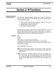
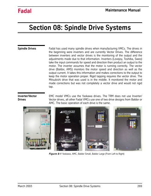
EMC model VMCs use the Yaskawa drives. The TRM does not use Inverter/<br />
Vector drives, all other Fadal VMCs use one of two drive designs from Baldor or<br />
AMC. The basic operation of each drive is the same.<br />
Figure 8-1 Yaskawa, AMC, Baldor Small, Baldor Large (From Left to Right)<br />
March 2003 <strong>Section</strong> <strong>08</strong>: <strong>Spindle</strong> <strong>Drive</strong> <strong>Systems</strong> 269
Fadal<br />
Maintenance Manual<br />
Inverter/Vector <strong>Drive</strong><br />
Inputs & Outputs<br />
<strong>Drive</strong> Ground<br />
The drive is required to have a ground connection. A green and yellow 16 AWG<br />
(10 AWG for 50 taper) wire grounds the drive to the machine chassis.<br />
Input Three Phase Power<br />
The three phase 230 VAC (460 VAC for 50 taper) input connects to terminals<br />
L1, L2 and L3 (R, S and T). This voltage should be between 220 and 240 volts<br />
(460 and 480 for 50 taper). When the voltage is too high, braking problems or<br />
damage to the drive may occur. When the voltage is too low, faults may occur<br />
while accelerating or cutting under load. The voltage leg to leg, in all three<br />
combinations, must be checked when installing new machines or changing the<br />
power source for the machine. If the voltage to the machine must be adjusted,<br />
it is better to be close to the lower end of the voltage range.<br />
Output Three Phase Power<br />
The drive outputs a three phase signal for the spindle motor. This signal varies<br />
in frequency and voltage depending on the motor’s speed. The output voltage<br />
is checked leg to leg. The output voltage should be about 80 VAC (60 VAC for<br />
50 taper) at 300 RPM 20 Hz and all three legs should be about equal (No more<br />
than a 2 volt variation). The output voltage should be about 200 VAC at 900<br />
RPM 60 Hz and should remain the same through 2500 RPM in the low range.<br />
If a problem is detected (Output fault), check the spindle motor leads with an<br />
Ohm meter by disconnecting the output leads at T1, T2 and T3. Check the<br />
leads going to the motor side leg to leg. Resistance readings between the three<br />
combinations of legs should each read between .05 to .8 ohms, and should<br />
read close to the same for each combination. The leg to ground resistance<br />
should be open when measured with an ohm meter and 80 meg ohms<br />
minimum when using a meg ohm meter for all three legs.<br />
<strong>Drive</strong> Control 6 Pin Molex Connector<br />
The drive control 6 pin molex connector has the inputs from the spindle<br />
controller card and the fault line from the inverter. Pin 1 is the common line for<br />
the spindle direction, pin 2 is the spindle reverse signal, pin 3 is the spindle<br />
forward signal, pin 4 is the common for speed control, pin 5 is the fault line and<br />
pin 6 is spindle speed command signal.<br />
For standard spindle operation the voltage output (20 volts DC) for the drive<br />
spindle direction (pin 2 reverse and pin 3 forward) is determined by the pulling<br />
of the appropriate signal to ground by activating K3 or K4 on the 1100-2<br />
board. When this voltage is pulled to about ground level the drive knows which<br />
direction to run in and is enabled.<br />
The drive also requires a speed command signal (0 - 10 volts DC through pin<br />
6). This signal, along with the direction signal, allows the spindle to be<br />
270 <strong>Section</strong> <strong>08</strong>: <strong>Spindle</strong> <strong>Drive</strong> <strong>Systems</strong> March 2003
Fadal<br />
Maintenance Manual<br />
operated. On a standard machine a 1.3 volt DC signal will result in a speed of<br />
about 300 RPM in low range.<br />
On machines with rigid tapping both the K3 and K4 relays are active, enabling<br />
drive, and a speed command of either positive or negative voltage (-10 to +10<br />
VDC) is used to determine spindle speed and direction.<br />
The fault line receives a voltage from the drive (10 VDC). An E-stop fault in<br />
another device will drop this voltage to zero by deactivating K2 on 1100-1<br />
board.<br />
Inverter Wye Delta 6 Pin Molex Connector<br />
Machines that use the Wye Delta motor configuration send input to the drive<br />
through pin 1 and pin 4 when in the delta mode.<br />
The High gain option sends signals through pin 3.<br />
Load Meter Output<br />
The drive produces an output voltage for load meter indication. This voltage<br />
output is proportional to the total current that the drive is using, and is<br />
displayed by the load meter as a percentage of the total current that the drive<br />
can develop or use.<br />
March 2003 <strong>Section</strong> <strong>08</strong>: <strong>Spindle</strong> <strong>Drive</strong> <strong>Systems</strong> 271
Fadal<br />
Maintenance Manual<br />
.<br />
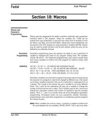
63,1'/(/2$'0(7(5:,5,1*',$*5$0<br />
Figure 8-2 1250-2 <strong>Spindle</strong> Load Meter Wiring Diagram<br />
Vector <strong>Drive</strong> Encoder 9 pin Molex Connector<br />
The encoder output signals A, /A, B & /B are input through this connector.<br />
There is a +5V ground line through this connector also.<br />
272 <strong>Section</strong> <strong>08</strong>: <strong>Spindle</strong> <strong>Drive</strong> <strong>Systems</strong> March 2003
Fadal<br />
Maintenance Manual<br />
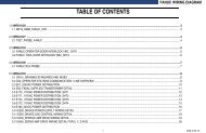
INVERTER ENCODER<br />
9 PIN MOLEX<br />
CONNECTOR<br />
Vector <strong>Drive</strong> with Rigid Tapping<br />
Output the encoder signals to the spindle controller PCBA through the Rigid<br />
Tapping Cable.<br />
RIGID TAPPING<br />
CABLE TO<br />
CONTROL BOARD<br />
WYE DELTA<br />
6 PIN MOLEX<br />
CONNECTOR<br />
LOAD METER<br />
INVERTER CONTROL<br />
6 PIN MOLEX<br />
CONNECTOR<br />
Figure 8-3 Baldor <strong>Drive</strong> Connections<br />
BALDOR DRIVE<br />
CONNECTIONS<br />
March 2003 <strong>Section</strong> <strong>08</strong>: <strong>Spindle</strong> <strong>Drive</strong> <strong>Systems</strong> 273
Fadal<br />
Maintenance Manual<br />
Adjustments<br />
Adjusting the Baldor<br />
Vector <strong>Drive</strong>s<br />
Auto Tuning/ Zero<br />
Balance<br />
Whenever a Baldor <strong>Drive</strong>’s DC Power Supply or a spindle controller card is<br />
replaced, it will need to be ZERO BALANCED to the machine. On Rigid Tapping<br />
machines in particular, the control sets the RPM and direction by supplying a<br />
precise -10 to +10 VDC control voltage through pins 4 and 6 at the control<br />
molex plug hanging on the right side of the inverter. To reverse the direction, a<br />
negative 0 to 10 VDC control voltage is sent. In rigid-tapping this allows the<br />
spindle motor to be rapidly reversed and ramped up and down. If the control<br />
voltage at idle is not exactly 0 VDC, then it is possible for the inverter to<br />
interpret it as a command to move in one direction or another at a slow speed.<br />
Verify that the inverter is installed properly, the spindle is off, and the keypad is<br />
installed. Use the keypad to complete the following procedure:<br />
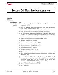
1) Install the display unit in inverter (if not<br />
already installed).<br />
2) The display should read OFF MOTOR<br />
SPEED REMOTE 0 RPM.<br />
3) Press PROG.<br />
4) Press the DOWN ARROW twice. The<br />
display will read LEVEL 2 BLOCKS.<br />
5) Press ENTER.<br />
6) Press the DOWN ARROW three times. The<br />
display will read AUTO TUNING.<br />
7) Press ENTER.<br />
8) Press the UP ARROW once. The display<br />
will read CMD OFFSET TRM.<br />
Figure 8-4 Keypad<br />
9) Press LOCAL.<br />
10) Press ENTER two times. The display will read TEST PASSED.<br />
11) Press RESET three times.The display will read PRESS ENTER FOR PRESET<br />
SPEED.<br />
12) Press the DOWN ARROW once. The display will read ENTER FOR<br />
PROGRAMMING EXIT.<br />
13) Press ENTER.<br />
274 <strong>Section</strong> <strong>08</strong>: <strong>Spindle</strong> <strong>Drive</strong> <strong>Systems</strong> March 2003
Fadal<br />
Maintenance Manual<br />
14) Press LOCAL. The display will read OFF MOTOR SPEED REMOTE 0 RPM.<br />
Baldor <strong>Spindle</strong> <strong>Drive</strong><br />
Parameter Usage for<br />
Fadal VMC<br />
The inverter replacements are INV-052 and INV-054. These two units are<br />
replacements for inverters (Toshiba, Sweo and Mitsubishi). They cannot be<br />
used in machines with Rigid Tapping. They do not have encoder feedback and<br />
do not require Zero Balancing or Auto Tuning. If the drive is Zero Balanced in<br />
error, recovery procedure is to set the ANA CMD Offset parameter to –1.<br />
NOTE: When in the inverter replacement unit, it is necessary to change to Input<br />
/ Operating Mode parameter to Keypad in order to make changes and return it<br />
to Fan Pump 2 Wire for operation.<br />
Baldor Vector <strong>Drive</strong>s require Zero Balancing whether rigid tapping is installed<br />
or not. The other tests and procedures are normally not necessary to perform.<br />
With INV-0070 the Motor Mag Amps parameter should be checked to insure<br />
that the current software is installed. To determine whether or not the<br />
parameters are changeable in the unit, change a parameter and power off<br />
machine, power on and check the parameter to determine if the new value was<br />
retained.<br />
Terms and<br />
Procedures:<br />
The Zero Balancing or Auto Tuning function matches the drive’s zero or<br />
speed reference point to the input speed command on pins 4 and 6 of the 6 pin<br />
Molex connector coming from the spindle controller board. The purpose is to<br />
match the zero point so that the speed command voltage input will obtain the<br />
same RPM of the motor for the same voltage for both positive and negative. If<br />
this is not set correctly problems such as hard reversals in Rigid Tapping,<br />
damaged threads, out-of-balance <strong>Spindle</strong> Motor, or <strong>Spindle</strong> turning slowly at<br />
idle in Rigid Tap standby may occur. Whenever the Input power to the machine,<br />
Baldor <strong>Drive</strong>, DC power supply, or a <strong>Spindle</strong> Controller card is replaced, it will<br />
need to be “Zero-Balanced” to the machine.<br />
March 2003 <strong>Section</strong> <strong>08</strong>: <strong>Spindle</strong> <strong>Drive</strong> <strong>Systems</strong> 275
Fadal<br />
Maintenance Manual<br />
TYPE:<br />
DISPLAY:<br />
--- “OFF MOTOR SPEED REMOTE 0 RPM”<br />
LOCAL<br />
“STOP MOTOR SPEED LOCAL 0 RPM”<br />
PROG<br />
“PRESS ENTER FOR PRESET SPEEDS”<br />
⇓ ⇓<br />
“PRESS ENTER FOR LEVEL 2 BLOCKS”<br />
ENTER<br />
“PRESS ENTER FOR OUTPUT LIMITS”<br />
⇓ ⇓ ⇓<br />
“PRESS ENTER FOR AUTOM TUNING”<br />
ENTER “CALC PRESETS P: NO”<br />
⇑ “CMD OFFSET TRM P: PRESS ENTER”<br />
ENTER<br />
“PRESS ENTER TO START THE TEST”<br />
ENTER “TEST PASSED PRESS ENTER”<br />
RESET “CMD OFFSET TRM P: PRESS ENTER”<br />
RESET<br />
“PRESS ENTER FOR AUTO TUNING”<br />
RESET<br />
“PRESS ENTER FOR PRESET SPEEDS”<br />
⇑ ⇑ ⇑ ⇑ “PRESS ENTER FOR INPUT”<br />
ENTER “OPERATING MODE P: FADAL SPECIAL”<br />
⇑ ⇑ ⇑ “ANA CMD OFFSET P: XX.X%” (Note: XX.X is the Offset value)<br />
RESET<br />
“PRESS ENTER FOR INPUT”<br />
RESET<br />
“PRESS ENTER FOR PRESET SPEEDS”<br />
DISPLAY<br />
“STOP MOTOR SPEED LOCAL 0 RPM”<br />
LOCAL<br />
“OFF MOTOR SPEED REMOTE 0 RPM”<br />
If the “ANA CMD OFFSET” value reads any value other than 0.0%, then the<br />
“Zero Balance Offset Trim” has been set.<br />
The Factory Parameters procedure is to load or re-load the factory<br />
parameters.<br />
Replacement Baldor Vector <strong>Drive</strong> unit will not run properly, but display is lit.<br />
The Factory Parameters may not have been loaded from the Eproms or PLC.<br />
Load Factory Parameters using INV-0017 Display Unit, and following<br />
procedure:<br />
276 <strong>Section</strong> <strong>08</strong>: <strong>Spindle</strong> <strong>Drive</strong> <strong>Systems</strong> March 2003
Fadal<br />
Maintenance Manual<br />
Keystrokes:<br />
PROG<br />
⇓ ⇓<br />
ENTER<br />
⇑ ⇑ ⇑<br />
Display shows:<br />
Off 0 0 RPM<br />
REM 0.0A 0.0 HZ<br />
PRESS ENTER FOR<br />
LEVEL 2 BLOCKS<br />
PRESS ENTER FOR<br />
OUTPUT LIMITS<br />
PRESS ENTER FOR<br />
MISCELLANEOUS<br />
ENTER RESTART AUTO/MAN<br />
P: CONTINUOUS<br />
⇑ ⇑ ⇑ FACTORY SETTINGS<br />
P: NO<br />
ENTER<br />
FACTORY SETTING<br />
⇑ P: YES<br />
ENTER<br />
FACTORY SETTINGS (Loading parameters)<br />
LOADING PRESETS<br />
FACTORY SETTING<br />
P: NO<br />
RESET<br />
RESET<br />
⇓ ⇓<br />
ENTER<br />
⇓ ⇓ ⇓<br />
PRESS ENTER FOR<br />
PRESET SPEEDS<br />
PRESS ENTER FOR<br />
LEVEL 2 BLOCKS<br />
PRESS ENTER FOR<br />
OUTPUT LIMITS<br />
PRESS ENTER FOR<br />
AUTO TUNING<br />
ENTER<br />
LOCAL<br />
CALC PRESET<br />
P: NO<br />
CALC PRESETS<br />
P: NO<br />
March 2003 <strong>Section</strong> <strong>08</strong>: <strong>Spindle</strong> <strong>Drive</strong> <strong>Systems</strong> 277
Fadal<br />
Maintenance Manual<br />
⇑<br />
⇑ ⇑<br />
RESET<br />
RESET<br />
RESET<br />
⇓<br />
CMD OFFSET TRIM<br />
P: PRESS ENTER<br />
TEST PASSED<br />
PRESS ENTER<br />
PRESS ENTER FOR<br />
PROGRAMMING EXIT<br />
ENTER STOP 0 V 0 RPM<br />
LOC 0.0 A 0.0 HZ<br />
LOCAL OFF O V 0 RPM<br />
REM 0.0 A 0.0 HZ<br />
278 <strong>Section</strong> <strong>08</strong>: <strong>Spindle</strong> <strong>Drive</strong> <strong>Systems</strong> March 2003
Fadal<br />
Maintenance Manual<br />
The Motor Tuning procedure tunes the drive to the motor. This is not<br />
necessary to perform because the factory parameters are set up for our<br />
motors. This procedure can be used for troubleshooting on units that will or will<br />
not retain parameter changes. These tests must be performed with motor<br />
unloaded (Belts must not be engaged): CUR LOOP COMP, FLUX CUR SETTING,<br />
FEEDBACK TESTS, and SLIP FREQ TEST.<br />
TYPE:<br />
DISPLAY:<br />
--- “OFF MOTOR SPEED REMOTE 0 RPM”<br />
LOCAL<br />
“STOP MOTOR SPEED LOCAL 0 RPM”<br />
PROG<br />
“PRESS ENTER FOR PRESET SPEEDS”<br />
⇓ ⇓<br />
“PRESS ENTER FOR LEVEL 2 BLOCKS”<br />
ENTER<br />
“PRESS ENTER FOR OUTPUT LIMITS”<br />
⇓ ⇓ ⇓<br />
“PRESS ENTER FOR AUTO TUNING”<br />
ENTER “CALC PRESETS P: NO”<br />
⇑ “CMD OFFSET TRM P: PRESS ENTER”<br />
ENTER<br />
“PRESS ENTER TO START THE TEST”<br />
ENTER “TEST PASSED PRESS ENTER”<br />
ENTER “CUR LOOP COMP P: PRESS ENTER”<br />
ENTER<br />
“PRESS ENTER TO START THE TEST”<br />
ENTER<br />
“TEST PASSED PRESS ENTER”<br />
ENTER “FLUX CUR SETTING P: PRESS ENTER”<br />
ENTER<br />
“PRESS ENTER TO START THE TEST”<br />
ENTER<br />
“TEST PASSED PRESS ENTER”<br />
ENTER “FEED BACK TESTS P: PRESS ENTER”<br />
NOTE: this test will test the encoder and encoder<br />
ENTER<br />
feedback to the Vector drive.<br />
“PRESS ENTER TO START THE TEST”<br />
(If test fails continue on with the rest of the tests. Then come<br />
back<br />
and use this test for troubleshooting the encoder circuit.)<br />
ENTER<br />
“TEST PASSED PRESS ENTER”<br />
ENTER “SLIP FREQ TEST P: PRESS ENTER”<br />
ENTER<br />
“PRESS ENTER TO START THE TEST”<br />
ENTER<br />
“TEST PASSED PRESS ENTER”<br />
ENTER<br />
“SPD CNTRLR CALC P: PRESS ENTER”<br />
ENTER<br />
“PRESS ENTER TO START THE TEST”<br />
ENTER<br />
“TEST PASSED PRESS ENTER”<br />
ENTER<br />
“PRESS ENTER FOR MENU EXIT”<br />
RESET<br />
“PRESS ENTER FOR AUTO TUNING”<br />
RESET<br />
“PRESS ENTER FOR PRESET SPEEDS”<br />
DISP<br />
“STOP MOTOR SPEED LOCAL 0 RPM”<br />
LOCAL<br />
“OFF MOTOR SPEED REMOTE 0 RPM”<br />
March 2003 <strong>Section</strong> <strong>08</strong>: <strong>Spindle</strong> <strong>Drive</strong> <strong>Systems</strong> 279
Fadal<br />
Maintenance Manual<br />
Motor Mag Amps for INV-0070<br />
On VHT machines equipped with INV-0070, during an acceleration cycle the<br />
spindle motor will slow down and then speed up several times, appearing<br />
similar in symptoms to that given by a failing encoder. Acceleration to full<br />
speed may take longer than the 2.2 seconds programmed into the drive.<br />
The Motor Mag Amps parameter in the INV-0070 <strong>Spindle</strong> <strong>Drive</strong> Unit is set too<br />
high by the Auto-Tuning procedure, and needs to be manually set to 22.<br />
In Auto Tuning, the parameter Flux Current is used to calculate the spindle<br />
Motor Mag Amps. Note: when running this self-tuning parameter the belts<br />
must first be disengaged to obtain an accurate measurement.<br />
280 <strong>Section</strong> <strong>08</strong>: <strong>Spindle</strong> <strong>Drive</strong> <strong>Systems</strong> March 2003
Fadal<br />
Maintenance Manual<br />
After following the Auto-Tuning procedure, and with the machine powered on:<br />
Keystrokes<br />
Baldor Display<br />
STOP MOTOR SPEED<br />
LOCAL 0 RPM<br />
Press PROG key<br />
Press ⇓ ⇓<br />
Press ENTER Key<br />
Press ⇑ ⇑ ⇑ ⇑ ⇑<br />
Press ENTER key<br />
PRESS ENTER FOR<br />
PRESET SPEEDS<br />
PRESS ENTER FOR<br />
LEVEL 2 BLOCKS<br />
PRESS ENTER FOR<br />
OUTPUT LIMITS<br />
PRESS ENTER FOR<br />
MOTOR DATA<br />
MOTOR VOLTAGE<br />
P: 230V<br />
Press ⇑ ⇑ ⇑ ⇑ key MOTOR MAG AMPS (This value will vary<br />
P: XX.X A between drives)<br />
Press ENTER key<br />
(Using the ⇑ ⇓ and shift keys change the value to 22)<br />
Press ENTER<br />
Press RESET<br />
Press RESET<br />
Press DISP<br />
PRESS ENTER FOR<br />
MOTOR DATA<br />
PRESS ENTER FOR<br />
PRESET SPEED<br />
OFF MOTOR SPEED<br />
REMOTE 0 RPM<br />
NOTE: Do not re-run the Auto-Tuning procedure without restoring value 22 in<br />
the Motor Mag Amps parameter.<br />
March 2003 <strong>Section</strong> <strong>08</strong>: <strong>Spindle</strong> <strong>Drive</strong> <strong>Systems</strong> 281
Fadal<br />
Maintenance Manual<br />
Yaskawa <strong>Drive</strong> 515<br />
(INV-0072)<br />
Set up Instruction,<br />
Initializing and<br />
balancing the drives<br />
1) Use this procedure for new drive installation, or replacement<br />
2) Power off Machine<br />
3) Install Yaskawa <strong>Drive</strong> with display unit.<br />
4) Power on Machine<br />
5) Press “MENU” to display **Main Menu Operation**<br />
6) Press “UP ARROW” 1 time to display ** Main Menu Initialize**<br />
7) Press “ENTER” to display **Select Language English**<br />
8) Press “UP ARROW” 3 times to display **Init Parameters /No Initialize**<br />
9) Press “ENTER” to display **A1-03= 0 /No Initialize**<br />
10) Press “UP ARROW” 1 time to display **A1-03= 2220 2- Wire Initial**<br />
11) Press “ENTER” to display **Entry Accepted**<br />
(loading parameters)<br />
Init Parameters<br />
No Initialize<br />
12) Press “MENU” to display ** Main Menu **<br />
Operation<br />
13) Press “ENTER” to display Frequency Ref<br />
U1-01= 1 RPM (RPM may be fluctuating)<br />
14) Press “JOG” and hold for 2 sec. Zero bias signal Frequency Ref (Balancing)<br />
U1-01= 1 RPM<br />
Any time press and hold the “JOG” for few second until balance 0 to 1 count, thus<br />
zero bias the command signal.<br />
282 <strong>Section</strong> <strong>08</strong>: <strong>Spindle</strong> <strong>Drive</strong> <strong>Systems</strong> March 2003
Fadal<br />
Maintenance Manual<br />
Yaskawa V7 (INV-<br />
0071) on Fadal EMC<br />
<strong>Spindle</strong> setup<br />
Instructions<br />
Before beginning, please note:<br />
All references to the V7 Manual are to TM 4315, dated 04/02/2001. The latest<br />
V7 manual can be downloaded from www.drives.com<br />
This instruction set assumes that the Yaskawa V7 hardware has been flashed<br />
with Fadal default software. Please check the Monitor Display U-10 and verify<br />
that it has value XXXX. The value in U-10 is the software version that is installed<br />
on this V7.<br />
The Monitor displays can be accessed from the keypad by pressing DSPL until<br />
the LED moves to MNTR. Then press DATA/Enter and use the L button to move<br />
to Monitor U-10. (See page 4-3 in the V7 Manual)<br />
Refer to page 4-2 in the V7 manual for more details on how to use the V7<br />
keypad.<br />
Setting Access level<br />
for parameters<br />
Displaying Fault<br />
Sequence<br />
Adjusting zero point<br />
on Analog velocity<br />
input<br />
Using the DSPL key on the V7 keypad, move the LED to PRGM. Select<br />
parameter n001 and press DATA/ENTER. Select value 5 and confirm data by<br />
pressing DATA/ENTER. This opens all n-constants for programming access.<br />
When you complete the task, reset n001 to 0 or 1.<br />
Using the DSPL key on the V7 keypad, move the LED to MNTR. Use the L<br />
button to move to MonitorU-09 and press DATA/ENTER. Use the L button to<br />
scroll through the last four faults. (See page 6-8 in the V7 Manual).<br />
When performing this adjustment, be sure that the CNC analog velocity output<br />
to the V7 is asking for zero speed. This procedure will show how to zero out any<br />
noise on the analog line between the CNC and the V7.<br />
Caution: If this procedure is performed when the CNC analog velocity<br />
signal is not zero, the spindle will not operate correctly.<br />
Using the DSPL key on the V7 keypad, move the LED to PRGM. Select<br />
parameter n069-Analog Frequency Reference Bias. This parameter has an<br />
adjustment range of –100 to 100. You will probably need a value of between –<br />
005 and 005.<br />
In order to verify that the value you select is correct, you will have to use the<br />
DSPL button to return the LED to FREF and verify that the value is zero. If it is<br />
not, repeat the procedure.<br />
March 2003 <strong>Section</strong> <strong>08</strong>: <strong>Spindle</strong> <strong>Drive</strong> <strong>Systems</strong> 283
Fadal<br />
Maintenance Manual<br />
Regenerative<br />
Resistors<br />
If on command of a rotating spindle to stop (M5), the <strong>Spindle</strong> Vector <strong>Drive</strong><br />
causes the motor to brake and coast, brake again and then coast alternately<br />
until it finally stops.<br />
If <strong>Spindle</strong> Vector <strong>Drive</strong> units are faulting on deceleration, resetting, and then<br />
faulting again, and resetting, this could be due to inoperative Regen Resistors,<br />
or Vector <strong>Drive</strong> parameters not matched to the resistors.<br />
Regenerative energy is the power generated when the power supplied to the<br />
motor is less than the motor requires to maintain the running RPM. The motor<br />
will begin to act like a generator as it slows to the new power level. When the<br />
motor is decelerated and begins to regenerate energy to the motor control, the<br />
control must dispose of this energy or burn up. Regenerative braking capability<br />
is the control’s ability to either absorb the energy or pass the energy<br />
somewhere else.<br />
Fadal uses the regenerative braking principles for stopping the spindle and for<br />
stopping the axis motors on AC brushless machines. Regenerative resistors are<br />
used to dispose of the excess energy created in the regenerative braking<br />
process. The regen resistors used for the spindle braking process are:<br />
ELE-0148 Regen Resistor 25 ohm<br />
ELE-0149 Regen Resistor 13 ohm 1100 Watt<br />
ELE-0150 Regen Resistor 24 ohm 1200 Watt<br />
ELE-0929 Regen Resistor 19.5 ohm 3205 Watt<br />
The 25 ohm regen resistor was used with the Toshiba 5 HP inverters, the 24<br />
ohm resistors were used with the Mitsubishi Brake unit, the 13 ohm have been<br />
used for years by most of the other drives, such as Baldor and AMC, including<br />
the Glentek brake unit, and the 19.5 ohm has been available for the last year or<br />
so. The smaller Mitsubishi drives had internal regen resistors. These regen<br />
resistors convert the excessive energy into heat and are connected to the<br />
spindle drive to absorb more energy either as a single resistor, or two in<br />
parallel, or even three in parallel. Do not make a combination of resistors<br />
with a total resistance of less than 6 ohms; this would cause excessive<br />
current in the circuit.<br />
To perform a basic test on the regen resistors, disconnect one or both wires for<br />
the regen resistors from the <strong>Spindle</strong> Vector <strong>Drive</strong> unit. With an ohmmeter,<br />
measure the resistance between the two wires of the Regen Resistor. The<br />
results should be the value of the regen resistor if one resistor, or the value of<br />
the resistor divided by the number of resistors connected in parallel. When two<br />
or more resistors are connected in parallel the wattage ratings of the individual<br />
resistors are added together, and define the amount of power that can be<br />
dissipated without burning up.<br />
284 <strong>Section</strong> <strong>08</strong>: <strong>Spindle</strong> <strong>Drive</strong> <strong>Systems</strong> March 2003
Fadal<br />
Maintenance Manual<br />
The braking circuit is the circuit, internal to the drive or on an external brake<br />
unit, that outputs the excessive power to the regen resistors. This circuit<br />
monitors the DC buss voltage of the drive and when it exceeds approximately<br />
385 volts DC (765 volts DC for 50 taper), the circuit will activate and dissipate<br />
the excess voltage. If the buss voltage reaches approximately 400 volts DC<br />
(800 volts DC for 50 taper), the drive will produce a “DC buss high” or “Buss<br />
Overvoltage” fault and base block the drivers causing the spindle to coast.<br />
Fadal’s current drives will automatically reset and try to regen again. If the drive<br />
faults after regen, then it resets, and the spindle will coast and brake alternately<br />
until it stops.<br />
If this symptom occurs on a Baldor Vector <strong>Drive</strong> and the Resistors test OK, then<br />
check the parameters for correct setting. To check the Baldor parameters with<br />
the keypad unit, depress the key for local mode, key for<br />
program mode, then the key until “Level 2 Block” is displayed.<br />
Press the key, key until “Brake Adjust” is displayed.<br />
Press the key, and then the key until “Resistor Ohms”<br />
is displayed. Set this value to be the net resistance value of the Regen<br />
Resistors as installed in the machine. Press the key until<br />
“Resistor Watts” is displayed. Set this value to that of the total Regen Resistors’<br />
wattage rating. Reset the drive to “Remote” and check performance.<br />
If the stopping load is heavy, as it is on the 15K RPM machines, then an<br />
additional Regen Resistor can be added in parallel to absorb more power and<br />
may correct the problem. Don’t forget to reset the parameters.<br />
If the deceleration causes the spindle to coast without an attempt to regen,<br />
then check the regen resistors, the regen circuit fuse, and then the regen<br />
circuit. In the current Baldor 15HP drives the regen circuit PCB can be replaced<br />
(INV-0068). In many cases the regen circuit can be disconnected and a Glentek<br />
brake unit (INV-0030) can be substituted for the regen circuit. (Please consult<br />
with Fadal before performing).<br />
To connect the Regen Resistors to the drives, use the following guide:<br />
Toshiba<br />
Mitsubishi or Glentek Brake<br />
AMC, Baldor Sweo, Sweo<br />
Baldor 10HP<br />
Baldor 15HT and VHT<br />
PA & PB<br />
PR & P<br />
R1 & R2<br />
B+/R1 & R2 with external fuse in series<br />
B+/R1 & R2 (some drives may have external fuse)<br />
March 2003 <strong>Section</strong> <strong>08</strong>: <strong>Spindle</strong> <strong>Drive</strong> <strong>Systems</strong> 285
Fadal<br />
Maintenance Manual<br />
Adjusting the AMC<br />
Vector <strong>Drive</strong><br />
The AMC VE150AD Vector drive works with all spindle controller cards. The<br />
AMC <strong>Drive</strong> HP rating must match the motor HP rating. If they are mismatched,<br />
the motor may not run to full speed.<br />
Figure 8-5 Match AMC <strong>Drive</strong> HP Rating with Motor HP Rating<br />
LEDs<br />
• Over Current - Red for over current; otherwise green<br />
• Over Voltage - Red for bus over voltage; otherwise green<br />
• Under Voltage - Red for bus under voltage; otherwise green<br />
• Regen - Red when active; otherwise green<br />
• Temp - Red for drive overtemp; otherwise green<br />
• Wye/Delta - Red for Wye, green for Delta<br />
• Fault - Red for fault; otherwise green<br />
• Encoder pulses - flashes when encoder pulses received<br />
Velocity Monitor Output<br />
Velocity Output P6-1 gnd P6-5 (0.1167V/100 RPM)<br />
286 <strong>Section</strong> <strong>08</strong>: <strong>Spindle</strong> <strong>Drive</strong> <strong>Systems</strong> March 2003
Fadal<br />
Maintenance Manual<br />
Switch Positions<br />
Table 1: Switch Positions<br />
# Switch Position<br />
1 Test/Offset Off (Offset)<br />
2 Magnetizing Current Only Off<br />
3 NC Off<br />
4 Torque/Velocity Mode Off (Velocity Mode)<br />
5 Reserved Off<br />
6 Velocity/Torque Mode On (Velocity Mode)<br />
7 +/- Direction Inhibit/Enable Select Off (Enable)<br />
8 5000/7500 Motor RPM On/Off (5000/7500 RPM)<br />
9 150/50 m/sec vel Loop Time Constant On<br />
10 10hp/15hp Motor On/Off (10/15hp)<br />
Note: Switches are located under cover; cover must be removed for access.<br />
Switches should be preset; only switch 8 and 10 are changed. See Figure 7-6.<br />
Figure 8-6 Switches are Preset<br />
Pots: (16 turn pots)<br />
• Deceleration Time* (CW to increase time)<br />
• Acceleration Time* (CW to increase time)<br />
• Flux (This pot has been removed)<br />
• Test/Offset<br />
• Ref. In Gain (signal gain)<br />
March 2003 <strong>Section</strong> <strong>08</strong>: <strong>Spindle</strong> <strong>Drive</strong> <strong>Systems</strong> 287
Fadal<br />
Maintenance Manual<br />
• Current Limit<br />
• Loop Gain<br />
* Accel & decel pots have no effect in rigid tap mode.<br />
Adjustments<br />
Switches and pots will be preset to initial settings by AMC.<br />
Switch Settings<br />
8 On-5000 RPM Off-7500 RPM<br />
10 On-10hp motor Off-15hp motor<br />
Pot Adjustments<br />
Adjust Accel, Decel, Loop gain, Offset, and Reference gain in the following<br />
order:<br />
Figure 8-7 Pot Adjustments<br />
1) ACCEL/DECEL: These pots have no effect in rigid tap mode. Machine must<br />
be off. Measure from P6-5 to test point below pot. 20k ohms for 2.2 sec<br />
Acc/Dec (11.8k for 3.5 sec). Turn CW to increase time.<br />
288 <strong>Section</strong> <strong>08</strong>: <strong>Spindle</strong> <strong>Drive</strong> <strong>Systems</strong> March 2003
Fadal<br />
Maintenance Manual<br />
2) LOOP GAIN: Remove P2 connector and install jumper plug (FOR & REV to<br />
COM). Turn the Loop Gain CW until it hums, then turn two turns CCW.<br />
Remove jumper plug and install P2 connectors.<br />
Figure 8-8 Remove Jumper Plug<br />
3) TEST/OFFSET:<br />
Rigid Tap Machines:<br />
In MDI enter “G84.2”.<br />
Adjust Offset for 0 VDC at P2 pins 4 and 6 (Ref In+ and Gnd).<br />
Non Rigid Tap Machines:<br />
Remove P2 connector and install jumper plug (FOR and REV to COM).<br />
Adjust Offset until spindle stops.<br />
Remove jumper plug and install P2 connector.<br />
4) REF. GAIN:<br />
In MDI, enter “S1000 M49 M3”.<br />
Adjust Ref. Gain for -1.22 VDC at Velocity Monitors (P6-1, gnd P6-5).<br />
Note: If pots were not preset, or if problems are encountered, preset pots as<br />
follows:<br />
5) LOOP GAIN: Turn fully CCW (minimum loop gain).<br />
6) CURRENT LIMIT: Turn fully CW (maximum current).<br />
7) REF. GAIN: Turn fully CW (maximum gain).<br />
March 2003 <strong>Section</strong> <strong>08</strong>: <strong>Spindle</strong> <strong>Drive</strong> <strong>Systems</strong> 289
Fadal<br />
Maintenance Manual<br />
8) TEST/OFFSET: Turn fully CCW, then * turns CW (middle).<br />
9) FLUX: Not Adjustable.<br />
10) ACCEL/DECEL: 20k ohms for 2.2 sec Acc/Dec (11.8k for 3.5 sec) (Measure<br />
from P6-5 to Test points below pots. Machine must be off when setting pot<br />
with ohmmeter).<br />
290 <strong>Section</strong> <strong>08</strong>: <strong>Spindle</strong> <strong>Drive</strong> <strong>Systems</strong> March 2003
Fadal<br />
Maintenance Manual<br />
Rigid Tapping<br />
(Optional Feature)<br />
Fadal Rigid Tapping<br />
Procedure<br />
This method of rigid tapping program is for Format 1.<br />
1) Place the rigid tapping test screw (SVT-0077) in the spindle.<br />
If using the test programs in the machine, use program # 6000. If not, enter the<br />
following program:<br />
G84.2<br />
G84.1 R0+0 Z-1. Q0.0714 F1000.<br />
X0.0001<br />
X-0.0001<br />
M99 P4<br />
2) Once the program is loaded, jog the Z axis down. Insert the indicator tip<br />
into the second thread from the bottom of the rigid tapping test screw. The<br />
tip must be touching the lower thread side at the half way point.<br />
Figure 8-9 Insert Indicator Tip Into Second Thread<br />
3) Type SETZ and press the ENTER key.<br />
4) Move the indicator back away from the test screw and start the test<br />
program. Observe that the program appears to be running correctly.<br />
5) Press the SINGLE STEP key. Verify that the rigid tapping test screw is back<br />
to the original position. Move the indicator back into position.<br />
6) Run the test. The indicator reading should not exceed .001” on either side<br />
of the indicator zero. If the indicator exceeds .001, adjust the ramp and<br />
gain in SETP. the ramp effects the center point (it should be at the zero) and<br />
the gain affects the total fluctuation (it should be within +/- .001).<br />
The following are starting points for each machine type:<br />
March 2003 <strong>Section</strong> <strong>08</strong>: <strong>Spindle</strong> <strong>Drive</strong> <strong>Systems</strong> 291
Fadal<br />
Maintenance Manual<br />
Software Version AC-<br />
0017 and Later<br />
-<br />
Table 2: Metric Screws<br />
7,500 RPM 7,500 RPM 7,500 RPM 7,500 RPM 7,500 RPM 10,000 RPM 15,000 RPM<br />
A Models L Models EMC 6535 40T 6535 50T ALL 1:2 ratio<br />
RPM Factor 0 0 0 0 0 0 0<br />
Orientation Factor 10 15 20 10 10 10 10<br />
Gain 60±15 45±15 45±15 70±15 50±15 90±15 90±15<br />
Ramp 100 or less 100 or less 100 or less 100 or less 100 or less 100 or less 100 or less<br />
Z Tap Gain Medium Normal Normal Medium Medium Medium Medium<br />
XYZ Ramp 160 160 160 250 250 160 160<br />
Table 3: Inch Screws<br />
7,500 RPM 10,000 RPM 15,000 RPM<br />
L Models ALL ALL<br />
RPM Factor 0 0 0<br />
Orientation Factor 15 10 10<br />
Gain 56±15 80±15 65±15<br />
Ramp 100 or less 100 or less 100 or less<br />
Z Tap Gain High High High<br />
XYZ Ramp 100 100 100<br />
292 <strong>Section</strong> <strong>08</strong>: <strong>Spindle</strong> <strong>Drive</strong> <strong>Systems</strong> March 2003
Fadal<br />
Maintenance Manual<br />
Before AC-0017<br />
Software Version<br />
-<br />
Table 4: Metric Screws<br />
7,500 RPM 7,500 RPM 7,500 RPM 7,500 RPM 7,500 RPM 10,000 RPM 15,000 RPM<br />
A Models L Models EMC 6535 40T 6535 50T ALL 1:2 ratio<br />
RPM Factor 0 0 0 0 0 0 0<br />
Orientation Factor 15 15 15 10 15 10 10<br />
Gain 38±15 38±15 38±15 70±15 50±15 58±15 45±15<br />
Ramp 100 or less 100 or less 100 or less 100 or less 100 or less 100 or less 100 or less<br />
Z Tap Gain Normal Normal Normal Medium Medium Normal Normal<br />
XYZ Ramp 160 160 160 250 250 160 160<br />
Table 5: Inch Screws<br />
7,500 RPM 10,000 RPM 15,000 RPM<br />
L Models ALL ALL<br />
RPM Factor 0 0 0<br />
Orientation Factor 15 10 10<br />
Gain 58±15 82±15 65±15<br />
Ramp 100 or less 100 or less 100 or less<br />
Z Tap Gain High High High<br />
XYZ Ramp 100 100 100<br />
March 2003 <strong>Section</strong> <strong>08</strong>: <strong>Spindle</strong> <strong>Drive</strong> <strong>Systems</strong> 293
Fadal<br />
Maintenance Manual<br />
Procedure for Setting GAIN Parameter:<br />
For Rigid Tapping with VMCs that have METRIC Ballscrews, the GAIN in<br />
SETP must be set to 80.<br />
Procedure for Setting Z TAP GAIN Parameter:<br />
For Rigid Tapping with VMCs that have METRIC Ballscrews, the Z TAP GAIN in<br />
SETP must be set to MEDIUM.<br />
Procedure for Setting XYZ RAMP Parameter:<br />
XYZ RAMP in SETP for all other AC <strong>Drive</strong> machines EXCEPT 6535 and 8535 are<br />
set at 160.<br />
The XYZ RAMP setting for the VMC6535 and 8535 is 250, instead of 160. The<br />
VMC6535 and 8535 also require SYS101.3 or later software.<br />
Procedure for Adjusting Amplifiers:<br />
The procedure for adjusting Loop Gain on AC Amplifiers is not changed when<br />
using the 25 IPM and the flashing LED on the controller card.<br />
In general, when updating from an earlier software version to AC0017, the<br />
amplifiers will not need adjusting, but, the displayed following errors in<br />
Program 5811 will be similar to those shown in the table above.<br />
Motors<br />
7.5 HP Motor The 7.5 HP motor is standard on EMC model VMC’s.<br />
10 HP Motor The 10 HP motor is standard on all VMC models except the EMC, 4020A,<br />
5020A, 6030 and 8030. It is continuously rated at 10 HP with a peak rating of<br />
15 HP.<br />
15 HP Motor The 15 HP motor is the standard motor on the following VMCs: 4020A, 5020A,<br />
6030 and 8030. It is an optional motor on all other VMC models. It is<br />
continuously rated at 15 HP with a peak rating of 22.5 HP.<br />
20 HP Motor The 20 HP Very Hi-Torque Motor is an optional motor available on the following<br />
model VMCs: 3020, 4020, 6030 and 8030. It is continuously rated at 20 HP<br />
with a peak rating of 30 HP.<br />
35 HP Motor<br />
(50 HP <strong>Drive</strong>) The 35 HP motor is a standard motor on the VMC 6535 50 taper. It is<br />
continuously rated at 35 HP with a peak rating of 50 HP.<br />
294 <strong>Section</strong> <strong>08</strong>: <strong>Spindle</strong> <strong>Drive</strong> <strong>Systems</strong> March 2003
Fadal<br />
Maintenance Manual<br />
WYE / DELTA Motors<br />
Standard motors are run in the wye mode only. Wye / Delta motors offer a<br />
flatter torque curve over the entire speed range of the motor/spindle system.<br />
Figure 8-10 WYE Delta Relay Wiring Diagram<br />
March 2003 <strong>Section</strong> <strong>08</strong>: <strong>Spindle</strong> <strong>Drive</strong> <strong>Systems</strong> 295
Fadal<br />
Maintenance Manual<br />
Belt <strong>Drive</strong> <strong>Systems</strong><br />
Posi-<strong>Drive</strong> Belt<br />
System<br />
The Posi-<strong>Drive</strong> Belt System features two belts that run on a 1-2 and 2-1<br />
reduction pulley arrangement.<br />
<strong>Spindle</strong> Belts Replacement on Auto Hi/low System<br />
The spindle drive belts are Gates 315K10. Gates manufactures the belts to<br />
Fadal specification. When replacing the spindle belts, use only the belts<br />
supplied by Fadal Machining Centers. The belts supplied by Fadal are sized.<br />
The following steps are for replacing the belts on the auto HI/LOW spindle:<br />
1) Verify that the VMC is aligned with the cold start indicators.<br />
2) Power off the VMC and lock out the main disconnect.<br />
3) Disconnect the air supply from the VMC.<br />
4) Remove four each of the 1/4” cap bolts on the Head Cover and remove the<br />
Head Cover. Cut all the wire ties holding the air lines and wires in place.<br />
5) The Auto Hi/Low pistons need to be released. Determine which piston is<br />
applying force on the belts, the upper piston is the low speed belt piston<br />
the lower piston is the high speed belt piston. To release the actuator, push<br />
the check valve into the actuator. With the check valve released, pull the<br />
idler away from the belts.<br />
Figure 8-11 Release Check Valve and Pull Idler Away from the Belts<br />
296 <strong>Section</strong> <strong>08</strong>: <strong>Spindle</strong> <strong>Drive</strong> <strong>Systems</strong> March 2003
Fadal<br />
Maintenance Manual<br />
6) Remove six each of the 1/4” hex bolts holding the Drawbar Cylinder<br />
assembly.<br />
Figure 8-12 Remove Hex Bolts Holding Drawbar Cylinder Assembly<br />
7) Remove the Drawbar Cylinder assembly.<br />
8) Disconnect the Orientation Bridge/Drawbar hall effect sensor 6 pin molex<br />
connector. Disconnect air line to the Orientation piston.<br />
Figure 8-13 Disconnect Orientation Bridge/Drawbar<br />
Figure 8-14 Disconnect Air Line to Orientation Piston<br />
March 2003 <strong>Section</strong> <strong>08</strong>: <strong>Spindle</strong> <strong>Drive</strong> <strong>Systems</strong> 297
Fadal<br />
Maintenance Manual<br />
9) Remove three each of the 3/8” socket head cap screws holding the<br />
Orientation Bridge assembly.<br />
Figure 8-15 Remove Socket Head Cap Screws<br />
10) Remove the Orientation Bridge assembly and front belt guide.<br />
Figure 8-16 Remove Orientation Bridge Assembly & Front Belt Guide<br />
11) Remove the Core Cover located on the bottom of the head.<br />
298 <strong>Section</strong> <strong>08</strong>: <strong>Spindle</strong> <strong>Drive</strong> <strong>Systems</strong> March 2003
Fadal<br />
Maintenance Manual<br />
12) Remove both of the 1/2” bolts to the rear belt guide, as well as the left 1/2”<br />
<strong>Spindle</strong> motor bolt.<br />
Figure 8-17 Remove Bolts to Rear Belt Guide<br />
Figure 8-18 Remove <strong>Spindle</strong> Motor Bolt<br />
13) Swing the spindle motor forward and remove the rear belt guide from the<br />
left side.<br />
Figure 8-19 Remove Rear Belt Guide<br />
March 2003 <strong>Section</strong> <strong>08</strong>: <strong>Spindle</strong> <strong>Drive</strong> <strong>Systems</strong> 299
Fadal<br />
Maintenance Manual<br />
14) Remove the 2 spindle drive belts.<br />
15) Replace the 2 spindle drive belts. Reassemble using the previous steps in<br />
reverse order.<br />
Motor Plate<br />
Tensioner Cable<br />
Machines equipped with a motor plate tensioner cable system, as shown in the<br />
figure below, will need adjusting when belts are replaced.<br />
Adjustment procedure:<br />
1) Disconnect the air supply from the machine. Remove the tension from the<br />
belts. Place an indicator as shown. Use either a dial indicator or a travel<br />
indicator.<br />
Figure 8-20 Place Indicator<br />
2) Once the indicator is in place, you will need two 9/16” open end wrenches<br />
to tighten and lock the cable tensioner screw.<br />
300 <strong>Section</strong> <strong>08</strong>: <strong>Spindle</strong> <strong>Drive</strong> <strong>Systems</strong> March 2003
Fadal<br />
Maintenance Manual<br />
3) Zero the indicator and slowly turn the 3/8” hex head bolt.<br />
Figure 8-21 Zero Indicator<br />
4) Adjust the screw until the plate moves.002 to .005 on the indicator.<br />
5) After adjusting, lock down the 3/8” jam nut with the other wrench while<br />
holding the adjuster screw. Watch the indicator to verify that there is no<br />
movement.<br />
Hydraulic Hi/low<br />
System<br />
The hydraulic hi/low system requires very little maintenance. It is an air over oil<br />
system with check valves. Periodically check that you can see fluid in the 1/4<br />
inch lines that go to the rear of the cylinder. If the lines have an excessive<br />
amount of bubbles then it is an indication that the oil level is low.<br />
Filling<br />
1) Remove the head cover.<br />
2) Disconnect the air supply from the machine.<br />
3) With the air source disconnected one actuator will still be engaged. To<br />
release the actuator, push the check valve into the actuator.<br />
4) With the check valve released, pull the idler away from the belts.<br />
5) Remove the 1/4“line that goes to the rear of the cylinder and fill with Mobil<br />
DTE heavy medium oil.<br />
March 2003 <strong>Section</strong> <strong>08</strong>: <strong>Spindle</strong> <strong>Drive</strong> <strong>Systems</strong> 301
Fadal<br />
Maintenance Manual<br />
!<br />
6) The reservoir is full when oil enters the 5/32 line on the actuator.<br />
WARNING<br />
DO NOT allow an excessive amount of oil to flow into the separator.<br />
7) Reattach the 1/4“line to the fitting on the cylinder.<br />
8) Repeat the above steps for the other range.<br />
!<br />
9) Reconnect the air supply to the machine.<br />
WARNING<br />
Verify that the oil lines are secure.<br />
10) In MDI, cycle between the high and low ranges about 10 times. This will fill<br />
the cylinders.<br />
MDI Example<br />
Type:<br />
MD,ENTER<br />
S.1, ENTER<br />
S.2, ENTER<br />
Repeat the S.1 and S.2 to continue switching ranges.<br />
7,500 RPM Poly<br />
Chain Belt<br />
This system features a single belt that runs on a 1-1 pulley arrangement.<br />
<strong>Spindle</strong> Belt Replacement<br />
The spindle drive belt is a Gates Poly-chain. Gates manufactures the belt to<br />
Fadal specification. When replacing the spindle belt, use only the belts supplied<br />
by Fadal Machining Centers.<br />
1) Verify that the VMC is aligned with the cold start indicators.<br />
2) Power off the VMC and lock out the main disconnect.<br />
3) Disconnect the air supply from the VMC.<br />
4) Remove four each of the 1/4” cap bolts on the Head Cover and remove the<br />
Head cover.<br />
302 <strong>Section</strong> <strong>08</strong>: <strong>Spindle</strong> <strong>Drive</strong> <strong>Systems</strong> March 2003
Fadal<br />
Maintenance Manual<br />
5) Cut all the wire ties holding the air lines and wires in place. Disconnect the<br />
1/4” assembly.<br />
Figure 8-22 Cut Wire Ties Holding Air Lines and Wires<br />
6) Remove each of the six 1/4” hex bolts to the Drawbar assembly.<br />
Figure 8-23 Remove Hex Bolts to Drawbar Assembly<br />
7) Remove the Drawbar assembly.<br />
March 2003 <strong>Section</strong> <strong>08</strong>: <strong>Spindle</strong> <strong>Drive</strong> <strong>Systems</strong> 303
Fadal<br />
Maintenance Manual<br />
8) Remove each of the four 3/8” cap bolts to the Orientation Bridge assembly.<br />
Figure 8-24 Remove Cap Bolts to Orientation Bridge Assembly<br />
9) Remove the Orientation Bridge.<br />
10) Loosen each of the two 1/2” hex bolts to the <strong>Spindle</strong> motor.<br />
Figure 8-25 Loosen Hex Bolts to <strong>Spindle</strong> Motor<br />
11) Swing the <strong>Spindle</strong> motor forward.<br />
12) Remove the <strong>Spindle</strong> drive belt.<br />
13) Install the new <strong>Spindle</strong> drive belt.<br />
14) Mount a Mag base with an indicator on the head and touch off the top-front<br />
edge of the spindle pulley.<br />
15) Set a zero reading while there is NO belt tension, then push back on the<br />
<strong>Spindle</strong> motor until about .0005" of deflection is seen on the indicator.<br />
304 <strong>Section</strong> <strong>08</strong>: <strong>Spindle</strong> <strong>Drive</strong> <strong>Systems</strong> March 2003
Fadal<br />
Maintenance Manual<br />
16) Tighten two each of the 1/2” hex bolts to the <strong>Spindle</strong> motor.<br />
17) Verify that the reading has not changed.<br />
Note: If the belt tension is too tight, then vibration will appear at the tool tip,<br />
and a poor finish may result.<br />
18) Reassemble using the previous steps in reverse order.<br />
Table 6: Application List for <strong>Spindle</strong> <strong>Drive</strong>s and Regen Resistors<br />
Part No. <strong>Spindle</strong> Type CE Size Regens Ohms Used<br />
Baldor (production):<br />
INV 0020 15HP 10000RPM HT No C 2 13 OR 19.5 19.5<br />
INV 0041 10HP 10000RPM No B 1 13 OR 19.5 19.5<br />
INV 0042 10HP 10000RPM No C 2 13 OR 19.5 19.5<br />
INV 0043 15HP 7500RPM HT No C 2 13 OR 19.5 19.5<br />
INV 0045 10HP 7500RPM No B 1 13 OR 19.5 19.5<br />
INV 0058 20HP 10000RPM VHT No C 2 13 OR 19.5 19.5<br />
INV 0070 25HP 10000RPM VHT Yes C 3 19.5 19.5<br />
INV 0073 35HP 7500RPM YES 3 19.5 19.5<br />
AMC (production):<br />
INV 0056 All types except VHT Yes 2* 13 OR 19.5 19.5<br />
Baldor (service):<br />
INV 0039 15HP 10000RPM HT Yes 1 C 2 13 OR 19.5 19.5<br />
INV 0044 10HP 7500RPM Yes 1 C 1 13 OR 19.5 19.5<br />
INV 0046 15HP 7500RPM HT Yes 1 C 2 13 OR 19.5 19.5<br />
INV 0052 10HP 10000RPM NCL No 1 13<br />
INV 0054 20HP 10000RPM NCL No 2 13<br />
Yaskawa (production):<br />
INV 0071 10HP 7500 RPM YES 2 13<br />
Others:<br />
INV 4551 TOSHIBA No 1 13<br />
INV 4556 SWEO No 1 13<br />
INV 4558 MITS. No INTERNAL NONE<br />
INV 4552 TOSHIBA No 2 13<br />
INV 4557 SWEO No 2 13<br />
INV 4558-320 MITS. (BRAKE+) No 2 13<br />
INV 4551-15 TOSHIBA No 1 13<br />
INV 4558-15 MITS. No INTERNAL NONE<br />
INV 4554 SWEO No 1 13<br />
March 2003 <strong>Section</strong> <strong>08</strong>: <strong>Spindle</strong> <strong>Drive</strong> <strong>Systems</strong> 305
Fadal<br />
Maintenance Manual<br />
Table 6: Application List for <strong>Spindle</strong> <strong>Drive</strong>s and Regen Resistors<br />
Part No. <strong>Spindle</strong> Type CE Size Regens Ohms Used<br />
INV 4558-320 MITS. (BRAKE+) No 2 13<br />
INV 4551-15 TOSHIBA No 1 13<br />
INV 4558-15 MITS. No INTERNAL NONE<br />
INV 4554 SWEO No 1 13<br />
INV 4554-175 BALDOR-SWEO No 1 13<br />
INV 4554Y-175 BALDOR-SWEO No 1 13<br />
INV 4554Y-180 BALDOR-SWEO No 1 13<br />
INV 4558Y MITS.CL No INTERNAL NONE<br />
INV 4555 SWEO No 2 13<br />
INV 4555-175 BALDOR-SWEO No 2 13<br />
INV 4555Y-175 BALDOR-SWEO No 2 13<br />
INV 4555Y-180 BALDOR-SWEO No 2 13<br />
INV 4558-315 MITS. (BRAKE+) No 2 13<br />
INV 4554-175-V15 BALDOR-SWEO No 1 13<br />
INV 4554-180-V15 BALDOR-SWEO No 1 13<br />
INV 4558-205 MITS. No INTERNAL NONE<br />
INV 4558-15CL MITS. No INTERNAL NONE<br />
INV 4558-305-6.5K MITS No INTERNAL NONE<br />
INV 4558-305-V15 MITS. (BRAKE+) No 2 13<br />
INV 4558-180-A BALDOR-SWEO No 2 13<br />
INV 4554-SP BALDOR-SWEO (single phase) No 1 13<br />
AMP-0064 Glentek, spindle drive, TRM No 1 19<br />
* FD2 uses 1 for 10HP, 2 for 15HP<br />
1 Cannot be used for current CE production<br />
306 <strong>Section</strong> <strong>08</strong>: <strong>Spindle</strong> <strong>Drive</strong> <strong>Systems</strong> March 2003
Fadal<br />
Maintenance Manual<br />
Tools Sticking in the<br />
<strong>Spindle</strong> During a<br />
Change Cycle<br />
There are many different solutions to problems leading to sticking tools, and<br />
although most machines experiencing a sticking tool problem will exhibit only<br />
one or two of these symptoms, it is better to check out all of them in each case.<br />
Inspection and elimination of the items on this list ensures a complete<br />
resolution to the problem.<br />
Please refer to testing procedure in item 18.<br />
1. Air Supply<br />
Pressure<br />
Minimum air pressure from the building to the machine must be greater than<br />
80 PSI, or 5.5 Bar. The supply volume must be adequate enough to not drop<br />
more than 5 PSI during a tool change cycle. Check for restrictions in the<br />
building plumbing, air filtration system, regulator bowl, lack of a closed loop in<br />
air supply plumbing around the shop, or excessive water in the air supply. A<br />
good test for inadequate volume is the observation of large pressure drops<br />
during a tool change cycle, or when other machinery in the shop uses air.<br />
Those machines with dual regulators should have the main regulator on the<br />
right side set no greater than 120 PSI (8 bar), and the secondary regulator at<br />
70-80 PSI (5-5.5 bar). The main regulator feeds the Drawbar Cylinder, and its<br />
output force is computed at 100 PSI, for example, 38 square inches x 100<br />
pounds per square inch or 3800 pounds pushing force. An increase of<br />
pressure to the Drawbar Cylinder proportionately increases Drawbar force at a<br />
factor of 38:1.<br />
Dual Air Regulatop set at 80 PSI and 120 PSI<br />
Exhaust Valve pipe nipple<br />
March 2003 <strong>Section</strong> <strong>08</strong>: <strong>Spindle</strong> <strong>Drive</strong> <strong>Systems</strong> 307
Fadal<br />
Maintenance Manual<br />
2. Drawbar Cylinder<br />
Hall Effects Switch<br />
3. Insufficient Air<br />
Volume: MAC In-Line<br />
Valve<br />
4. Air Leaks; Exhaust<br />
Valve<br />
5. Air Leaks; Exhaust<br />
Valve Nipple<br />
6. Air Leaks;<br />
Drawbar Cylinder<br />
Bushing<br />
7. Air Leaks;<br />
Drawbar Cylinder<br />
Plate<br />
Tool "Popping" can be reduced on machines equipped with Drawbar Cylinder<br />
Hall Effects switches, by checking the adjustment on the switch. If the switch is<br />
up too high, then the Z-axis may start up prematurely in the Tool Extraction<br />
cycle, wrenching the tool out of the spindle. Note that there is a new parameter<br />
in SETP labelled “Do you have Air Valve feedback” This does not mean that<br />
electric signals are returning to the control from the air valve. It means that<br />
there could be Hall Effects switches on the Idlers and Drawbar Cylinder, and if<br />
so, the answer would be “YES”. To answer “NO” might mean that the control<br />
will ignore any such feedback and Z-axis may lift off the tool prematurely.<br />
In some cases, the rear MAC In-Line valve that delivers air to the Drawbar<br />
Cylinder may have reduced output by volume. There have been cases of 40%<br />
reduction in airflow when this valve experiences a failure. This condition will not<br />
allow the Drawbar Cylinder to fill fast enough to provide enough impact to<br />
operate properly. A simple test is to swap the valve with another in the manifold<br />
and retest.<br />
Inside the Exhaust Valve on top of the Drawbar Cylinder is a diaphragm valve/<br />
seat. A tiny pinhole leak in the diaphragm will cause the valve to leak out the<br />
exhaust and not fill up the Drawbar Cylinder. Inspect the diaphragm visually for<br />
a rupture, and replace if necessary. Part numbers are VLV-0032 and VLV-0033<br />
for repair kits, the large valve style or the small valve style, respectively.<br />
The pipe nipple that attaches the Exhaust Valve to the Drawbar Cylinder<br />
Housing may be cracked from overtightening, and then leak. Inspect and<br />
replace, if necessary.<br />
Test for an air leak with soapy water sprayed around the air lines. The bronze<br />
bushing that guides the Drawbar Cylinder Shaft may be worn, or damaged, or<br />
too rough internally to prevent premature wear to the O-ring around the shaft.<br />
Disassemble the Drawbar Cylinder and inspect/replace the O-ring and<br />
bushing. A new bushing design will be available soon to not only house a<br />
second O-ring, but provide a smoother surface to reduce O-ring wear. It will be<br />
retrofittable to all earlier Drawbar Cylinders. It has been included in the Sticking<br />
Tool Retrofit kit listed on the last page.<br />
Another source of air leaks can be from the large O-ring around the Drawbar<br />
Cylinder Plate, and to discover this will require disassembly and inspection.<br />
The Drawbar Cylinder Plate itself can be cracked or distorted. When<br />
reassembling, please note the correct location of the magnet for the Hall<br />
Effects switch, and avoid cutting the large O-ring accidentally.<br />
3<strong>08</strong> <strong>Section</strong> <strong>08</strong>: <strong>Spindle</strong> <strong>Drive</strong> <strong>Systems</strong> March 2003
Fadal<br />
Maintenance Manual<br />
8. Air Leaks;<br />
Hydraulic Actuator<br />
Assembly Bolts<br />
9. Air Leaks;<br />
Coolant-Thru<br />
Drawbar Cylinder<br />
Two of the 1/4-20 bolts used to mount the Hydraulic Actuator assembly<br />
penetrate the Drawbar Cylinder housing, and may not have been sealed with<br />
teflon tape adequately. Test with soapy water for air leaks, sealing the bolt<br />
threads with teflon tape.<br />
On Coolant-Thru Drawbar Cylinders equipped with a brass "shuttle valve" there<br />
is a port fitted to the top of the housing that was designed to feed air first to the<br />
shuttle valve, and then down the Drawbar Shaft to clear off the tool holder. The<br />
existence of this port is a leak to the Drawbar Cylinder, bleeding off air from the<br />
chamber. Earlier versions had a large port, and later versions have an orifice<br />
restricting airflow.<br />
A mechanical air valve can be installed to draw air for the shuttle valve back at<br />
the main regulator, instead of from the Drawbar Cylinder. Contact the Fadal<br />
Parts Department for details.<br />
10. Orientation<br />
Bridge "Lifting"<br />
11. Black Oxide Tool<br />
Holders<br />
12. Dirty Tool<br />
Holders<br />
13. Spring Pilot;<br />
Oversized Diameter<br />
When the Drawbar Cylinder pushes downward with 3000 to 4000 pounds<br />
force, and meets resistance in extracting the tool, an upward force is created<br />
that wants to "lift" the Orientation bridge up from the head casting. The 3 bolts<br />
that hold the Bridge down to the Belt Guide resist this upward movement.<br />
During a tool change, inspect the movement upward of the Orientation Bridge.<br />
A closer inspection might reveal stripped bolt threads, distortion of the Bridge<br />
plate, damaged pockets in the Bridge plate containing the 3 bolt heads. A new<br />
design Orientation Bridge and Belt Guide will have 4 bolts holding it down, and<br />
is included in the Sticking Tools Retrofit kit listed below.<br />
We recommend "Side Ground" tool holders. Those manufactured with "Crush<br />
Ground" or those with Black Oxide coated finish are more vulnerable to tool<br />
sticking problems.<br />
Foreign matter on the tool holder taper, and sometimes coolant gel from<br />
evaporated coolant on the taper, will contribute some to the problem. As a test,<br />
clean the tapers thoroughly, and spray an anti-rust lubricant such as LPS-3 or<br />
Ironclad (not WD40) on the taper and retest.<br />
The outer diameter of the Spring Pilot, either non-locking or locking, may be<br />
too large and fit too tightly into the spindle bore. Check for score marks on the<br />
pilot, which would indicate galling of the surface. Recently the Knock-Out Cap<br />
was redesigned to provide a capturing ridge to contain the upper points of the<br />
crown of the spring pilot. With the increased tool retention forces, we have seen<br />
some distortion of the pilot. Check the inner bore of the <strong>Spindle</strong> Rotor where<br />
the Spring Pilot is located and carefully stone any developed burrs.<br />
March 2003 <strong>Section</strong> <strong>08</strong>: <strong>Spindle</strong> <strong>Drive</strong> <strong>Systems</strong> 309
Fadal<br />
Maintenance Manual<br />
14. Spring Pilot; Ball<br />
Pockets Incorrect<br />
With the Spring Pilot removed from the spindle, carefully inspect the 4 ball<br />
pockets and insert (4) BRG-0004 1/4 steel balls into them. Remount the Spider<br />
on top of them. The balls should easily retract full travel when pressed, and<br />
return under gravity force. Any binding indicates a misformed pocket. The<br />
pockets themselves should show no sign of distortion that might restrict ball<br />
travel when heavily loaded.<br />
15. Drawbar Scored Inspect the shaft of the Drawbar itself, particularly where the Belleville springs<br />
may contact it. Should the Belleville springs twist around the Drawbar, they<br />
may shift off of their rims, and dig into the Drawbar, and resist up and down<br />
movement. The introduction of hardened flat washers every 10th Belleville<br />
spring helps prevent the stack shift. A newly designed Drawbar and Spring<br />
Pilot will be available soon that has a larger diameter shaft which should<br />
restrict the stack shift from occurring. See the Sticking Tools Retrofit kit below.<br />
16. Damaged<br />
Drawbar<br />
At the bottom of the Drawbar is a pocket for the Pull Stud of the tool holder, and<br />
around its perimeter are 8 holes for the 3/16 inch balls to grasp the Pull Stud.<br />
Earlier Drawbars had a deeper pocket, and CAT tools were pushed out of the<br />
spindle by the lowest rim of this pocket contacting the pull stud. Eventually the<br />
rim of the Drawbar was distorted and the balls might not retract as smoothly as<br />
expected. Later Drawbars have a shorter pocket so that the Drawbar shaft<br />
pushes on the top of the pull stud, rather than on its base. A damaged Drawbar<br />
rim might prevent the pull stud from extraction smoothly.<br />
17. Damaged Floater The Floater is located by two 3/16 balls in a circular track in the spindle throat.<br />
These hold the Floater steady when the Drawbar is pressed through it, and the<br />
step at the bottom of the Floater allows the 8 3/16 balls to retract out of the<br />
way to release the tool. Should the Floater be damaged in a way that allows it<br />
to move with the Drawbar, the Pull Stud cannot be extracted from the Drawbar.<br />
Replace the damaged Floater, if necessary.<br />
18. Testing<br />
Procedure<br />
Use the following page to measure Drawbar performance, both before<br />
inspection, and after completion of the procedures outlined in this bulletin, for<br />
comparison.<br />
310 <strong>Section</strong> <strong>08</strong>: <strong>Spindle</strong> <strong>Drive</strong> <strong>Systems</strong> March 2003
Fadal<br />
Maintenance Manual<br />
MEASURING<br />
DRAWBAR<br />
PERFORMANCE<br />
In order to measure the amount of push force that the Drawbar Cylinder has<br />
upon the tool, place a tool holder into the spindle (without a tool in it) and Jog<br />
the machine slowly downward in Z-axis onto the SVT-0066 Pressure Gauge-<br />
3000PSI. Once the gauge begins to register after contact, press the Tool In/Out<br />
button to release the tool. Measure how much net force is pressed upon the<br />
tool by the Drawbar.<br />
Use the following chart to figure the amount of force that is lost.<br />
Drawbar Cylinder force ________(38 x #PSI)<br />
Less Drawbar return spring - 100<br />
Less Belleville Springs- 800<br />
Net Force<br />
= ________<br />
Less Pressure Gauge reading - ________<br />
Lost Pressure Force<br />
= ________<br />
Drawbar Cylinder force is the air pressure in PSI multiplied by 38. Figuring the<br />
Drawbar return spring to be about 100 pounds, and the resistance from the<br />
Belleville Springs to be 800 pounds, we deduct 900 from the Drawbar Cylinder<br />
force. This gives us the expected Net Force.<br />
However, it is necessary to measure with the Pressure Gauge what the Net<br />
Force actually is. The difference is lost forces, such as binding, friction losses,<br />
etc. A higher number Lost Pressure Force will result in Sticking Tools.<br />
The technician should check items 1 through 17 in this section and the<br />
corrections should restore any missing forces and allow more of the Drawbar<br />
Cylinder pressure to reach the tool holder.<br />
March 2003 <strong>Section</strong> <strong>08</strong>: <strong>Spindle</strong> <strong>Drive</strong> <strong>Systems</strong> 311
Fadal<br />
Maintenance Manual<br />
DRB-0024 Sticking<br />
Tools Kit, 10K LDB<br />
DRB-0025 Sticking<br />
Tools Kit, 10K LDB-<br />
CT=<br />
312 <strong>Section</strong> <strong>08</strong>: <strong>Spindle</strong> <strong>Drive</strong> <strong>Systems</strong> March 2003
Fadal<br />
Maintenance Manual<br />
Tap-Tap Cycle<br />
The purpose of the Tap-Tap Cycle is to release tools that are stuck in the<br />
spindle. When the Drawbar Cylinder is activated, the Drawbar Hall Effect switch<br />
is activated to indicate that the tool was successfully released. If the switch is<br />
not activated a repeating Tap-Tap cycle is initiated, where it applies the<br />
Drawbar Cylinder pressure, releases, and then applies the Orientation camroller<br />
to the spindle pulley, and over again. This process aimed at knocking the<br />
tool loose will repeat until a timeout and fault mode is reached.<br />
To adjust the Tap-Tap cycle drawbar Hall Effect switch (ELE-0145), temporarily<br />
reverse the air lines to the Drawbar Cylinder and the Orientation Bridge, so that<br />
when a M19 is called in MDI, the Drawbar Cylinder will be activated constantly.<br />
May need to use a 5/32" to 1/4" adapter fitting. The Hall Effect switch reads the<br />
drawbar cylinder magnet (left side of orientation bridge).<br />
Using "DI" and "DS" from the command line, display switches. Locate<br />
DRAWBAR and watch the "01". While adjusting the switch position lower (away<br />
from the drawbar cylinder), when it changes to "00", rotate the switch upward<br />
until it changes back to "01", and then further upward 1/2 turn, and tighten<br />
locknut. Don't forget to restore air lines properly.<br />
This process enables the control to know the difference between a tool that is<br />
stuck in the spindle, and one that was removed. If it was stuck the Tap-Tap<br />
cycle is initiated.<br />
In some situations, most likely in VMC15 or 15000 RPM machines, where there<br />
is not a Hi/Low idler assembly installed, you may experience trouble extracting<br />
tools. A quick and simple test of the Tap-Tap cycle can be achieved by<br />
disconnecting the 1/4" air line to the drawbar cylinder (at either end). Without<br />
any tools in the spindle or in the turret pocket, make a tool change. The slide<br />
will advance to the spindle, the drawbar cylinder solenoid will activate, blowing<br />
air out into the room, and begin the Tap-Tap cycle. Over and over the machine<br />
should blow air out the disconnected line, and then stop and activate the<br />
orientation cylinder and tap on the pulley, and then repeat until it faults. If the<br />
drawbar cylinder Hall Effect switch is not properly adjusted, it may continue<br />
making a tool change without using the drawbar.<br />
Also, if the machine does not have Hi/Low idlers, then jumpers must be<br />
installed at 1060/J9/10-11 and 1060/J11/4-5. These jumpers fool the control<br />
into thinking that there is an idler assembly installed so that it will know to<br />
monitor the drawbar cylinder switch and not ignore it. If no jumpers are<br />
present, then add them using about 4 inches of # 16 wire and Molex pins.<br />
A further solution for those customers who have the Tap-Tap cycle and yet still<br />
have a problem is the Drawbar Cylinder Adapter assembly. This device uses<br />
March 2003 <strong>Section</strong> <strong>08</strong>: <strong>Spindle</strong> <strong>Drive</strong> <strong>Systems</strong> 313
Fadal<br />
Maintenance Manual<br />
the air output to the drawbar cylinder from the air valve assembly to trigger a<br />
valve that supplies up to 120 PSI air to the Drawbar Cylinder to extract the<br />
stuck tool. It is simple to install and setup and should be used in conjunction<br />
with the Tap-Tap cycle.<br />
Sanding the upper one-third of the taper of the spindle with a fine grade (600<br />
grit) of sand paper also helps (100RPM for 10 seconds).<br />
Troubleshooting the Tap-Tap cycle:<br />
1) Check the Drawbar Hall Effect switch and its adjustment.<br />
2) The wires connect to J9 pins 1,2 & 3 for the Drawbar Hall Effect switch.<br />
3) The 1040 Mill Interface board reads the switch and activates the relays for<br />
the air valves.<br />
4) The 1030 Computer Interface board communicates the instructions<br />
between the 1040 and the CPU 1400 board and the 1610 Program<br />
Module.<br />
<strong>Spindle</strong> Drawbar and<br />
Belleville Spring<br />
Replacement<br />
Drawbar Removal<br />
1) Remove the Drawbar Cylinder Assembly.<br />
2) Remove the Orientation Bridge Assembly.<br />
3) Place a long 3/8 inch drive extension or similar item in the spindle and jog<br />
the head down until the extension is under slight tension between the<br />
drawbar and the table. Caution: Do not place high tension on the<br />
extension; it only needs to support the drawbar. Place a piece of wood<br />
between the extension and the table, if needed.<br />
4) Remove the Knock out cap (on locking drawbars only).<br />
5) Place pilot tool on spring pilot.<br />
6) Use wheel puller to depress the spring pilot.<br />
7) Remove spring retainers.<br />
8) Remove wheel puller.<br />
9) Jog head up and remove the extension and the drawbar. Be careful not to<br />
drop the ball bearing.<br />
314 <strong>Section</strong> <strong>08</strong>: <strong>Spindle</strong> <strong>Drive</strong> <strong>Systems</strong> March 2003
Fadal<br />
Maintenance Manual<br />
10) Now remove the belleville springs or the floater.<br />
11) To reinstall, reverse the above steps.<br />
Replace Belleville<br />
Springs<br />
1) Remove drawbar (See <strong>Section</strong> A).<br />
2) Using a spring hook or a magnet remove the belleville springs (Be sure to<br />
remove any broken pieces).<br />
3) Install replacement springs starting with first one cupped downward and<br />
reverse every other one. The quantity will vary depending on the spindle<br />
pocket size (See the spring quantity chart).<br />
4) Reinstall drawbar.<br />
Remove Floater<br />
(This will rarely be<br />
necessary.)<br />
1) Remove the drawbar (See <strong>Section</strong> A).<br />
2) The floater has two ball bearings that hold it in place. Using a floater<br />
removal tool or a magnet pull the ball bearing toward the center and the<br />
floater should come out. If badly damaged the floater can be difficult to<br />
remove.<br />
March 2003 <strong>Section</strong> <strong>08</strong>: <strong>Spindle</strong> <strong>Drive</strong> <strong>Systems</strong> 315
Fadal<br />
Maintenance Manual<br />
<strong>Spindle</strong> Belleville<br />
Springs Quantity<br />
Chart<br />
There have been many spindle and spring retainer combinations over the<br />
years. To determine the number of Belleville Springs in a spindle, three factors<br />
have to be considered: The depth of the spring pocket in the spindle, the depth<br />
of the spring retainer and the width of the Belleville springs. The following chart<br />
is a guide line for the number of springs and may vary slightly from spindle to<br />
spindle.<br />
This chart covers the most common depths of spindles. In most cases the<br />
deeper spring retainers will use one less spring then number in the chart.<br />
<strong>Spindle</strong> Type <strong>Spindle</strong> Depth Number of<br />
springs<br />
10K Non-Locking 2.00 19<br />
Remarks<br />
10K Non-Locking 3.00 30<br />
10K Non-Locking 4.25 43<br />
7.5K & 15K Non-Locking 4.326 44<br />
7.5K & 15K Non-Locking 4.627 47<br />
10K Locking 2.00 18<br />
10K Locking 3.00 29<br />
10K Locking 4.25 42<br />
10K Locking 4.326 40<br />
10K Locking 4.627 44<br />
316 <strong>Section</strong> <strong>08</strong>: <strong>Spindle</strong> <strong>Drive</strong> <strong>Systems</strong> March 2003
Fadal<br />
Maintenance Manual<br />
<strong>Spindle</strong> Pre-Load<br />
Measuring the<br />
<strong>Spindle</strong> Pre-Load<br />
1) Place a Pressure Gage (SVT-0066) on the table and align it with the <strong>Spindle</strong><br />
nose.<br />
2) Set an indicator on the Head and touch the indicator tip on the nose of the<br />
<strong>Spindle</strong>.<br />
3) Jog the head (Z axis) down until the pressure gage reads 1000 pounds.<br />
4) Zero the Indicator.<br />
5) Jog the head (Z axis) up until it is no longer in contact with the pressure<br />
gage.<br />
6) Depress the “Tool In Out” Button on the keyboard.<br />
7) Release Button.<br />
8) Read the value on the indicator.<br />
If adjustment is necessary on a adjustable spindle then turn the spindle<br />
preload adjustment nut clockwise to tighten and counter clockwise to loosen.<br />
Listed below are the "Fadal factory recommended specifications" for the<br />
various spindles.<br />
RPM Rating Preload setting: (Deflection at 1,000 psi. Lube Method<br />
15,000 / 10,000. 0014-.0017 (Can Not be adjusted) Air/Oil<br />
7,500 0013-.0015 (Adjustable preload) Grease Pac<br />
10,000 0013-.0015 (Adjustable preload) Grease Pac<br />
15,000 0017-.0019 (Adjustable preload) Grease Pac<br />
<strong>Spindle</strong> Duty Cycle<br />
It is the recommendation of the Engineering Department in conjunction with the<br />
bearing manufacturers that the following procedures be followed to increase<br />
spindle life under extreme operating conditions.<br />
<strong>Spindle</strong>s operating under 8,000 RPMs need no cool down period regardless of<br />
on time or load to the tool.<br />
Fadal recommends that <strong>Spindle</strong>s operating at over 8,000 RPMs for extended<br />
periods of time should be shut down for a period of at least 20 minutes after<br />
March 2003 <strong>Section</strong> <strong>08</strong>: <strong>Spindle</strong> <strong>Drive</strong> <strong>Systems</strong> 317
Fadal<br />
Maintenance Manual<br />
every 5 hours of continuous operation. This will allow cooling of the races and<br />
re-lubrication of the grease lubricated bearings. The actual load to the spindle<br />
is not a factor a these higher RPMs. The time period should be monitored as<br />
closely as possible to increase spindle life.<br />
Air Positive Flow<br />
System<br />
318 <strong>Section</strong> <strong>08</strong>: <strong>Spindle</strong> <strong>Drive</strong> <strong>Systems</strong> March 2003
Fadal<br />
Maintenance Manual<br />
<strong>Spindle</strong>s<br />
7.5K & 10K Grease<br />
Packed <strong>Spindle</strong>s<br />
Components<br />
The 7.5K and 10K grease packed spindles are self contained units.<br />
Functional Description<br />
These spindles are belt driven and require no maintenance. There is air<br />
supplied to the spindle on the top and bottom for positive pressure.<br />
These spindles are self-contained, therefore they should be replaced when<br />
bad. The 7.5K spindle has a non-locking drawbar and the 10K has a locking<br />
drawbar.<br />
15K Air/Oil <strong>Spindle</strong><br />
Components<br />
The 15K air/oil system consists of a spindle, a spindle lubricating oil supply<br />
pump, a vacuum pump, a positive displacement injector (PDI) block, a<br />
coalescent filter, four pressure switches (2-15psi, 1-80psi, 1-265psi) mounted<br />
on a pressure switch manifold, an electronic control board with wire harness,<br />
and various standard plumbing parts. This spindle is also belt driven.<br />
Functional Description<br />
The electronic control board controls the ON time of solenoids for oil and air<br />
while monitoring:<br />
• Supply oil pressure<br />
• Oil reservoir level<br />
• Supply air pressure<br />
• Air/oil pressure to the upper and lower bearings of the spindle<br />
The pump pressurizes oil to the PDI block. Oil pressure is monitored by an oil<br />
pressure switch. Air is supplied to the PDI block through a coalescing filter from<br />
a solenoid valve. Air pressure to the machine is monitored by an air pressure<br />
switch. The PDI block mixes air and oil. The two lines carry the air/oil mixture to<br />
the upper and lower bearings. The pressure of each line is monitored by a<br />
pressure switch. A vacuum pump is used to remove any oil that blows by the<br />
upper or lower bearings, to reduce oil leakage.<br />
March 2003 <strong>Section</strong> <strong>08</strong>: <strong>Spindle</strong> <strong>Drive</strong> <strong>Systems</strong> 319
Fadal<br />
Maintenance Manual<br />
<strong>Spindle</strong>/Lube Pump/<br />
Control<br />
<strong>Spindle</strong><br />
Bearings<br />
Ceramic Steel Hybrid<br />
Lubrication<br />
Air and oil pressure feed back control<br />
Operating temp. Ambient +20°F during steady state operation<br />
Motor Power<br />
15 HP<br />
Max. Speed<br />
15,000 RPM<br />
Max. Cut 3/8”<br />
Max. Depth of cut 3/8”<br />
Max. Tool diameter 3/4”<br />
<strong>Spindle</strong> Lube Pump<br />
Lube Pump<br />
Oil<br />
Oil Cycle<br />
Oil Filtration<br />
Air Flow<br />
Air Filtration<br />
Venturi Vacuum Pump<br />
Control Circuit<br />
Supply voltage<br />
Overload protection<br />
Air and oil feed back pressure control<br />
Mobil DTE 797 Steam Turbine Oil or equivalent<br />
Nominal 0.025 cc/injection cycle<br />
5 micron absolute<br />
160 SCFH @ 80 psi<br />
10 micron<br />
9" Hg<br />
120 VAC<br />
2 amp (fused)<br />
<strong>Spindle</strong> Removal<br />
1) Verify that the VMC is aligned with the cold start indicators.<br />
2) Power off the VMC and lockout/tagout the main disconnect.<br />
3) Disconnect the air supply from the VMC.<br />
4) Remove the head cover by removing the four 1/4 -20 socket head cap<br />
screws.<br />
5) Disconnect the electrical connection to the orientation bridge assembly at<br />
the six pin connector plug.<br />
6) Disconnect the two 1/4” air lines from the orientation bridge assembly.<br />
7) Remove the draw bar cylinder plate by removing the six 1/4” hex head bolts<br />
and set them aside.<br />
8) Remove the orientation bridge assembly and the front belt guide by<br />
removing the three 3/8” socket head cap screws.<br />
9) To swing the spindle motor forward, loosen the 1/2” hex bolt on the left<br />
side of the spindle motor and loosen the two 1/2” hex bolts on the right<br />
side of the spindle motor.<br />
320 <strong>Section</strong> <strong>08</strong>: <strong>Spindle</strong> <strong>Drive</strong> <strong>Systems</strong> March 2003
Fadal<br />
Maintenance Manual<br />
!<br />
10) Remove the spindle drive belt.<br />
WARNING<br />
Use heavy duty work gloves when handling the heated spindle and pulley.<br />
11) Using a propane torch, direct the flame at the spindle pulley for<br />
approximately 6-10 minutes while slowly rotating the spindle. Maintain an<br />
even amount of heat throughout the pulley. The spindle pulley will drop<br />
down on the spindle when it is expanded enough to remove it from the<br />
spindle.<br />
12) Label and disconnect the upper and lower spindle cooling lines from the<br />
spindle. Disconnect the 5/32” air seal line from the lower spindle flange.<br />
This will be reused later as the air supply to the vacuum pump.<br />
13) Loosen the upper spindle retainer clamping screw.<br />
14) Remove the six 1/2” hex bolts and lock washers from the upper spindle<br />
retainer and lift the retainer from the spindle. Ensure that the cooling line O-<br />
ring and the spindle O-ring are removed.<br />
!<br />
15) Remove the coolant supply manifold by removing the 1/4” socket head cap<br />
screw. Move it out of the work area and support it so that the lines are not<br />
crimped.<br />
WARNING<br />
Support the spindle with a wooden block while performing the next step.<br />
16) Remove the six 3/8” socket head cap screws holding the spindle in the<br />
head, remove the old spindle and O-ring. Discard the used O-ring. Save the<br />
socket head cap screws.<br />
Component<br />
Installation<br />
Regulator/ Separation Block Mounting<br />
The regulator should be installed at the same location that it was at when the<br />
machine was originally installed.<br />
Installing <strong>Spindle</strong> Lubrication Pump<br />
Mount the spindle lubrication pump plate assembly to the side of the column<br />
above the way lube pump. On older model VMCs four 1/4-20 holes may need<br />
to be drilled and tapped; use the spindle lubrication pump plate assembly as a<br />
template.<br />
Vacuum Pump Installation<br />
Using the vacuum pump base as a template, drill through and tap two 1/4-20<br />
holes into the left counter weight arm on top of the column. Mount the vacuum<br />
pump to the plate.<br />
March 2003 <strong>Section</strong> <strong>08</strong>: <strong>Spindle</strong> <strong>Drive</strong> <strong>Systems</strong> 321
Fadal<br />
Maintenance Manual<br />
Pressure Manifold Mounting<br />
Mount the pressure switch manifold block on the inside bottom of the cabinet,<br />
by removing the four knockouts and drilling the necessary mounting holes.<br />
Control Board Mounting<br />
Mount the control board on the inside upper right side of the cabinet, by drilling<br />
the necessary holes to attach.<br />
Solenoid Modification<br />
1) Remove the solenoid fitting on the solenoid closest to the rear of the<br />
cabinet.<br />
2) Install the T-fitting and 1/4” to 5/32” reducer on solenoid.<br />
322 <strong>Section</strong> <strong>08</strong>: <strong>Spindle</strong> <strong>Drive</strong> <strong>Systems</strong> March 2003
Fadal<br />
Maintenance Manual<br />
<strong>Spindle</strong> Tram<br />
1) Level Machine.<br />
2) Adjust TABLE GIBS, SADDLE GIBS, and HEAD GIBS.<br />
3) Adjust TABLE STRAPS.<br />
Watch for Turcite gibs:.0003"<br />
Non-Turcite gibs: .0005"<br />
4) Adjust SADDLE STRAPS and HEAD STRAPS.<br />
5) Above items must be checked properly or <strong>Spindle</strong> Tram test may be invalid.<br />
6) Establish X,Y plane by mounting an indicator in spindle. Touch off granite<br />
block at points A,B,C, and D by moving in MDI as follows:<br />
Zero indicator at A Y-10. F75. GI (Move to C and record)<br />
Y5.X5. (Move to B and record)<br />
X-10. (Move to D and record)<br />
Y5.X5. (Verify zero at A)<br />
7) Sweep indicator over the same four points by rotating spindle by hand.<br />
Check each point at E,F,G,H.<br />
March 2003 <strong>Section</strong> <strong>08</strong>: <strong>Spindle</strong> <strong>Drive</strong> <strong>Systems</strong> 323
Fadal<br />
Maintenance Manual<br />
Adjusting <strong>Spindle</strong><br />
Tram<br />
If spindle is to be installed, follow this procedure. Clean all surfaces and<br />
replace O-rings. Mount spindle in head using 6 SoCap bolts. Check tram as<br />
described above. Determine which position shows the most POSITIVE error.<br />
Imagine a pointer using diagram below, and align arrow on diagram to point<br />
towards most POSITIVE direction. Loosen 6 bolts slightly, and tighten according<br />
to the diagram bolt pattern with a torque wrench. First, tighten to 25<br />
Ft.Lb. and then to 55 Ft.Lb. Retest tram, and install upper O-Ring and clamp<br />
ring. Tighten these 6 bolts also using the following bolt pattern.<br />
15K Air/Oil <strong>Spindle</strong><br />
Installation<br />
1) Verify that the lower spindle O-ring is in good condition (not cut, torn or<br />
pinched).<br />
2) Position the 15K spindle in the head with O-ring seal.<br />
3) Install six socket head cap screws and evenly tighten them until they are<br />
snug. Torque the socket head cap screws in increments of 25 ft/lbs then 40<br />
ft/lbs.<br />
4) Place a magnetic dial indicator base on the spindle. Check the run out on a<br />
true plate. The run out should be less than .0005"(.0127mm).<br />
5) Shim the spindle if necessary to achieve a proper run out specification.<br />
6) Verify that the upper spindle retainer O-rings are in good condition (not cut,<br />
torn or pinched).<br />
7) Align the upper spindle retaining ring with the cooling passage. Lightly<br />
cover the hex head bolts with gasket sealing compound and evenly tighten<br />
them until snug. Torque the hex head bolts to 30 ft/lbs.<br />
8) Snugly tighten the retainer ring clamping screw.<br />
324 <strong>Section</strong> <strong>08</strong>: <strong>Spindle</strong> <strong>Drive</strong> <strong>Systems</strong> March 2003
Fadal<br />
Maintenance Manual<br />
9) Using a propane torch, direct the flame at the spindle pulley for<br />
approximately 5 minutes. Maintain an even amount of heat throughout the<br />
spindle pulley.<br />
!<br />
WARNING<br />
Use heavy duty work gloves when handling the heated spindle and spindle<br />
pulley.<br />
10) While the spindle pulley is heating, place the spindle pulley locating spacer<br />
(part # SVT-0096) on the ground surfaces of the head.<br />
11) Find the orientation mark on the top of the spindle housing and position the<br />
spindle so that the orientation mark is toward the front of the VMC. Secure<br />
the spindle so that it will not rotate when installing the spindle pulley.<br />
12) Place the spindle pulley on the spindle so that it rests on the locating<br />
spacer, at the same time align the orientation marks of the spindle and the<br />
spindle pulley.<br />
13) Allow the spindle pulley to cool to the touch before continuing with the<br />
assembly.<br />
14) Install the spindle drive belt.<br />
15) Place a dial indicator against the top front edge of the pulley and set it at<br />
zero.<br />
16) Swing the spindle motor towards the rear of the machine until the dial<br />
indicator reads .0003" (.0076mm).<br />
!<br />
WARNING<br />
Do not adjust the belt tension more than the recommended deflection.<br />
17) Tighten the 1/2” hex bolt on the left side of the spindle motor and the two<br />
1/2” hex bolts on the right side of the spindle motor.<br />
18) Install the orientation bridge assembly and front belt guide with the three<br />
3/8” socket head cap screws, and tighten them snugly.<br />
19) Install the draw bar cylinder plate with the six hex head bolts, and tighten<br />
the bolts.<br />
20) Connect the six pin connector plug into the orientation bridge assembly.<br />
21) Connect the two 1/4” air lines to the orientation bridge.<br />
22) Connect the coolant lines removed from the old spindle to the upper and<br />
lower connections on the new spindle.<br />
March 2003 <strong>Section</strong> <strong>08</strong>: <strong>Spindle</strong> <strong>Drive</strong> <strong>Systems</strong> 325
Fadal<br />
Maintenance Manual<br />
Wiring Harness<br />
Installation<br />
1) Using the figure below and the following clarifying instructions, install the<br />
wire harness assembly inside the control cabinet.<br />
2) The spindle lubrication pump cable runs through any available existing wire<br />
way knockout located on the bottom of the control cabinet.<br />
3) Attach the spindle pump’s black wires to black wire J2-3 from the 1980-0<br />
control board. Connect the spindle pump’s white wire to the white wire J2-4<br />
from the 1980-0 control board. The green spindle pump wire should be<br />
grounded to the nearest convenient system grounding terminal.<br />
4) Remove the wire marked “1” from the spindle overload relay. Splice the<br />
wire marked spindle overload relay from the 1980-0 control board onto the<br />
spindle overload relay wire. Reattach the spindle overload relay wire to the<br />
spindle overload relay.<br />
326 <strong>Section</strong> <strong>08</strong>: <strong>Spindle</strong> <strong>Drive</strong> <strong>Systems</strong> March 2003
Fadal<br />
Maintenance Manual<br />
5) Inspect the machine for the version of mill interface board (1040) installed.<br />
The 15K spindle system requires a 1040-2B or newer mill interface board.<br />
Update the machine to the newer card if necessary.<br />
Plumbing <strong>Spindle</strong><br />
1) Pull four 5/32” air lines from the back of the machine up through the cable<br />
ways to a point just above the head next to the motor mounts. Leave a<br />
portion of the lines coiled for extra.<br />
Note: Check the machine for the High/Low option 5/32” lines. If these lines are<br />
present they can be used instead of pulling the new lines through the cable<br />
ways. Label these lines as 21, 22, 25 and 26 if used.<br />
2) Pull the 5/32” air seal line previously removed from the old spindle up<br />
through the cable way. Connect it to the fitting (32) on the vacuum pump.<br />
3) Insert three 5/32” lines in 3 foot lengths into the fittings located on the<br />
lower spindle flange. The three lines are the inlet line stamped “AIR/OIL IN”<br />
(23), the exhaust line stamped “AIR OUT” (29), and the vacuum line<br />
stamped “VACUUM” (27).<br />
4) Cover the two lines (23, 27) with 1/4” nylon tubing from the fittings to the<br />
point where they enter the head.<br />
5) Feed the line from the fitting on the lower flange stamped with “AIR/OIL IN”<br />
(23) up through the head to where the four lines are located next to the<br />
motor mount.<br />
6) Insert three 5/32” lines in 3 foot lengths into the three fittings located on<br />
the upper bearing retainer just below the pulley. The three lines are the inlet<br />
line stamped “AIR/OIL IN” (24), the exhaust line stamped “AIR OUT” (30),<br />
and the vacuum line stamped “VAC/AIR” (28).<br />
7) Feed the inlet line, stamped “AIR/OIL IN” (24) on the upper bearing<br />
retainer, into the head and up along side the other lines from the lower<br />
flange.<br />
8) The four lines coming to the head from the back of the machine are two PDI<br />
lines (21, 22) and two Pressure switch lines (25, 26). Be sure to keep these<br />
lines labeled.<br />
9) Connect one air/oil PDI line (21) and one pressure switch line (25) to the<br />
double end of the Y-fitting.<br />
10) Connect the inlet line, stamped “AIR/OIL IN” (23) on the lower flange, to<br />
the single end of the Y-fitting.<br />
March 2003 <strong>Section</strong> <strong>08</strong>: <strong>Spindle</strong> <strong>Drive</strong> <strong>Systems</strong> 327
Fadal<br />
Maintenance Manual<br />
11) Connect the other air/oil PDI line (22) and the other pressure switch line<br />
(26) to the double end of the second Y-fitting.<br />
12) Connect the inlet line, stamped “AIR/OIL IN” (24) on the upper bearing<br />
retainer, to the single end of the Y-fitting.<br />
13) Feed the two outlet lines, one from the lower flange Stamped “AIR OUT”<br />
(29) and one from the upper bearing retainer stamped “AIR OUT” (30), into<br />
the inside of the head and fasten them to any hose with a nylon wire tie.<br />
These two lines are the exhaust lines.<br />
14) Verify that a 5-in-line valve system or air-seal valve is installed on the<br />
machine. If they currently do not exist on the machine, order and install<br />
part number VLV-0006.<br />
15) Feed the lower vacuum line (27) up through the head to the vacuum pump<br />
and connect it to the Y-fitting (27) on the vacuum pump.<br />
16) Feed the upper vacuum line (28) along the top of the head to the vacuum<br />
pump and connect it to the fitting (28) on the vacuum pump.<br />
17) Verify that all plumbing lines are installed correctly. Secure loose lines as<br />
necessary with nylon wire ties.<br />
Install Component<br />
Plumbing<br />
1) Complete the installation of all lines for the air supplies, oil supply lines and<br />
pressure feed back lines.<br />
2) Before filling the spindle lubrication pump with the recommended oil (Mobil<br />
DTE 797 Steam Turbine Oil), remove the reservoir and inspect the float on<br />
the level switch. The cutaway ridge on the float should be on top. Remove<br />
the float and reverse it if the ridge is on the bottom of the float.<br />
Start Up After Installation<br />
1) Fill the reservoir on the spindle lube tank with Mobil DTE 797 ISOVG32 oil or<br />
equivalent. Any other viscosity oil will cause damage to the spindle.<br />
2) Check the wiring on the circuit control board.<br />
3) Plug in the air supply line to the machine and set the regulators to 80 psi for<br />
the left regulator and 120 psi for the right regulator.<br />
4) Remove the oil pressure line from the oil pressure switch fitting on the<br />
pressure switch manifold. Hold the line over a collecting container. Prime<br />
the spindle lubricating pump by depressing the solenoid button with a<br />
small screwdriver until all air bubbles are removed from the oil pressure<br />
line.<br />
328 <strong>Section</strong> <strong>08</strong>: <strong>Spindle</strong> <strong>Drive</strong> <strong>Systems</strong> March 2003
Fadal<br />
Maintenance Manual<br />
Note: Observe the color of the oil coming out of the oil pressure line. If the color<br />
is DARK BROWN, there is way lube oil in the pump. Prime the line until the<br />
way lube oil is flushed out. The spindle oil color is LIGHT YELLOW, prime<br />
the oil pressure line until the oil coming out is this color.<br />
5) Replace the oil pressure line at the oil pressure switch fitting.<br />
6) Press the reset button on the control board and observe the LED lights (if<br />
any lights are illuminated then take the action necessary to correct the<br />
condition).<br />
7) Prime the PDI block with the spindle inlet lines at the Y-fitting on the head<br />
disconnected. Prime until oil is seen flowing through both of the 5/32” lines<br />
coming out of the PDI block. Prime by pressing the spindle lubrication<br />
pump solenoid button with a small screwdriver. Press it for 10 seconds and<br />
release it for 10 seconds and repeat until oil flow is satisfactory. Priming<br />
can only be done while the air is flowing to the spindle. If air is not flowing<br />
then press and release the reset button. This will provide 2 minutes of air<br />
flow.<br />
8) After priming the PDI block, run the spindle at 10,000 RPM and monitor the<br />
temperature for 20 minutes. If the temperature is high, check the PDI block<br />
operation.<br />
9) Run the spindle at 15,000 RPM and monitor the temperature. The spindle<br />
temperature should be below 100°F after one-half hour. This is the steadystate<br />
temperature of the spindle.<br />
10) If the temperature exceeds this specification, verify the oil line connections<br />
and the oiling cycle.<br />
Normal Operation<br />
The air/oil spindle lubrication system operates automatically using the 1980-0<br />
control board. The pressure switches will cause an emergency stop condition if<br />
the system is not operating properly.<br />
On start-up the 1980-0 Control Board LEDs operate as follows:<br />
1) Power on without air and oil to the machine.<br />
HB - blinking.<br />
OIL, AP, LEV, AIR - illuminate.<br />
OE, UAP, LAP - remain out for 13 seconds from power ON, then illuminate.<br />
OIL - illuminates, turns OFF in 15 seconds from power ON.<br />
2) Power on with air and oil to the machine (Green CNC button depressed).<br />
March 2003 <strong>Section</strong> <strong>08</strong>: <strong>Spindle</strong> <strong>Drive</strong> <strong>Systems</strong> 329
Fadal<br />
Maintenance Manual<br />
HB - blinking.<br />
OIL, AIR - illuminate.<br />
AP, LEV, OE, UAP, LAP - remain OFF.<br />
OIL - illuminates, turns OFF in 15 seconds from power ON.<br />
AIR - illuminates, turns OFF in 2 minutes from power ON.<br />
3) While the spindle is running.<br />
HB - blinking.<br />
OIL - illuminates only during oiling cycle for 15 seconds every 20 minutes.<br />
AIR - illuminated continuously, turns OFF 2 minutes after the spindle stops.<br />
AP, LEV, OE, UAP, LAP - remain OFF.<br />
Troubleshooting<br />
LED Indications<br />
HB LED - Normally flashes indicating that the 1980-0 control board is<br />
functioning properly.<br />
AP LED - This LED will illuminate when air pressure does not reach or drops<br />
below 80 psi. Air pressure less than 80 psi will cause an emergency stop of<br />
machine.<br />
Adjust the regulator air output pressure to clear this condition. If the regulator<br />
fails to maintain pressure repair or replace the regulator.<br />
If the air pressure is correct, check the setting of the air pressure switch. The<br />
slotted adjusting screw, on top of the switch, should be two turns from flush<br />
with the switch housing. Check for loose wires. The switch may be faulty if<br />
adjusting it has no effect.<br />
LEV LED - This LED will illuminate when the oil level in the spindle lube<br />
pump tank is low. A low oil level signal will cause a feed hold on the<br />
machine until corrected.<br />
Check the sight glass for an adequate level in the supply tank. If tank level is<br />
okay, then check for binding, an inverted float, the level float sticking or loose<br />
electrical wiring.<br />
OE LED - This LED will illuminate when the oil pressure does not reach or<br />
drops below 265 psi. Low oil pressure will cause an emergency stop of the<br />
machine.<br />
Correct the oil pressure output, by adjusting the air pressure to the pump/PDI<br />
block. Loose wires, broken hoses, a bad pressure switch or failure of the<br />
330 <strong>Section</strong> <strong>08</strong>: <strong>Spindle</strong> <strong>Drive</strong> <strong>Systems</strong> March 2003
Fadal<br />
Maintenance Manual<br />
solenoid can also cause this indication. If the oil pressure is still low, verify that<br />
the air and oil filters are clean replace elements if required.<br />
UAP LED/LAP LED - These LEDs will illuminate if the oil pressure to the<br />
upper or the lower spindle bearings drops below 15 psi. Low bearing<br />
pressure will cause an emergency stop of the machine.<br />
Loose wires, broken hoses, a faulty pressure switch or the pressure switch<br />
adjusted too low can also cause this indication. The adjusting screw, on top of<br />
the pressure switch, should be flush with the top of the housing.<br />
Reset Condition<br />
If any of the above errors occur remedy the problem. Press the reset button<br />
located near the top of the 1980-0 control board to clear the error signal. The<br />
reset button can be pressed while the spindle is running. The 1980-0 control<br />
board will also reset if the power to the CNC is turned off then on.<br />
Coolant Thru the<br />
<strong>Spindle</strong><br />
Electrical<br />
Mechanical<br />
Coolant-Thru<br />
<strong>Spindle</strong> Seal Kit<br />
Instructions<br />
The coolant thru pump receives its three phase power from the transformer<br />
routed though three fuses to a overload starter relay that is controlled by mist<br />
coolant output from 1100-1 TB2-23 & 24. K22 (protected by F18) is turned on<br />
with a M8 or M7 (SETP setting).<br />
When the pump is activated, it draws coolant into the filter and then to the<br />
pump. The coolant is pumped up to the Drawbar Cylinder. The coolant flows<br />
down though the Drawbar Cylinder rod to the seals. The system is designed to<br />
ride together under the pressure of the three weak springs, and then<br />
hydraulically press together when coolant is present. It will need lubricant<br />
present at least 1 or 2 times a day to prevent premature abrading. This is<br />
accomplished by activating the coolant thru.<br />
1) With a tool already installed in the spindle, remove Drawbar Cylinder and<br />
Hydraulic Actuator assembly, if equipped.<br />
2) Using ¼-20 x 2 bolts, thread into CNT-0041 Seal Retainer Ring to hold it<br />
into the Orientation Bridge upon disassembly.<br />
3) Remove the Orientation Bridge and lay aside, being careful not to fold nylon<br />
air lines.<br />
March 2003 <strong>Section</strong> <strong>08</strong>: <strong>Spindle</strong> <strong>Drive</strong> <strong>Systems</strong> 331
Fadal<br />
Maintenance Manual<br />
4) Remove existing Ceramic Seal retainer and Locking Drawbar Knock-out<br />
cap.<br />
5) Using Gear Puller and SVT-0073 Drawbar Removal Tool, remove LDB<br />
Spring Pilot and replace inner and outer O-rings with HDW-0155 and HDW-<br />
0158 respectively.<br />
6) Re-install Spring Pilot.<br />
7) Now, replace HDW-0177 O-ring on Drawbar and mount new style knock<br />
out cap using original bolts.<br />
!<br />
WARNING: Do not handle the graphite seal with bare hands, wear latex gloves<br />
while installing. Finger oils contain acids which will shorten the service life of<br />
the seal.<br />
8) Assemble Ceramic seal face into its boot, and press into pocket on new<br />
retainer with smooth or unmarked side into pocket first. Install HDW-0177<br />
O-ring onto DRB-0015 Knock-Out cap.<br />
9) Mount new Retainer and Ceramic Seal assembly onto Knockout Cap,<br />
rotating slightly over the HDW-0177 O-ring. Do not level Ceramic Seal face<br />
as in previous versions; it is self-leveling.<br />
10) Replace O-rings in the Orientation Bridge, and replace the CNT-0033<br />
Graphite seal.<br />
11) Note that the CNT-0041 Retainer has two similar sized O-rings but has the<br />
HDW-0156 on the outer piston portion, and the HDW-0150 inside at the<br />
top, and HDW-0155 inside at the bottom.<br />
12) Place a small amount of Plain water, NOT oil or COOLANT, on the white<br />
Ceramic Seal face before mounting the Orientation bridge. Align the<br />
Orientation Bridge with the SVT-0071 Coolant-Thru Alignment tool, and<br />
reassemble it and the Drawbar Cylinder. Don’t forget to remove the two<br />
bolts holding the seal retainer.<br />
13) After reassembly, run the spindle at S150 RPM for 30 seconds to level out<br />
the Ceramic Seal, and lap the Graphite to the Ceramic Seal face.<br />
Determining the<br />
Leak Location<br />
1) Examine area under the Orientation Bridge and around the pulley. If the<br />
wires for the orientation and drawbar down hall effect switches has coolant<br />
on them then the O-rings (HDW-0150) at the top of the Piston Housing,<br />
coolant –thru (CNT-0042) are most likely the problem.<br />
2) Remove the Drawbar Cylinder and the Orientation Bridge (don’t forget your<br />
coolant-thru retainer screws).<br />
332 <strong>Section</strong> <strong>08</strong>: <strong>Spindle</strong> <strong>Drive</strong> <strong>Systems</strong> March 2003
Fadal<br />
Maintenance Manual<br />
3) With an indicator, check the level of the Ceramic Seal, this seal needs to be<br />
level and is manufactured to a 2 Light-Bars flatness. Run out less than<br />
.0003” (.0076mm)<br />
4) Verify that the Piston assembly moves freely up and down under the spring<br />
pressure on the orientation bridge.<br />
5) Inspect the Graphite and Ceramic seals for pitting or chipping.<br />
6) Check the O-rings in the Piston assembly.<br />
7) Install a 10 micron filter.<br />
March 2003 <strong>Section</strong> <strong>08</strong>: <strong>Spindle</strong> <strong>Drive</strong> <strong>Systems</strong> 333
Fadal<br />
Maintenance Manual<br />
Hydraulic Actuator<br />
Set-up<br />
334 <strong>Section</strong> <strong>08</strong>: <strong>Spindle</strong> <strong>Drive</strong> <strong>Systems</strong> March 2003
Fadal<br />
Maintenance Manual<br />
40 Taper BT & CAT<br />
Pull Studs<br />
March 2003 <strong>Section</strong> <strong>08</strong>: <strong>Spindle</strong> <strong>Drive</strong> <strong>Systems</strong> 335
Fadal<br />
Maintenance Manual<br />
336 <strong>Section</strong> <strong>08</strong>: <strong>Spindle</strong> <strong>Drive</strong> <strong>Systems</strong> March 2003