Programming Guide 11/2002 Edition - Flint Machine Tools, Inc.
Programming Guide 11/2002 Edition - Flint Machine Tools, Inc.
Programming Guide 11/2002 Edition - Flint Machine Tools, Inc.

Create successful ePaper yourself
Turn your PDF publications into a flip-book with our unique Google optimized e-Paper software.
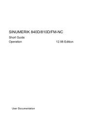
<strong>Programming</strong> <strong>Guide</strong> <strong>11</strong>/<strong>2002</strong> <strong>Edition</strong><br />
Cycles<br />
SINUMERIK 840D/840Di/810D
SINUMERIK 840D/840Di/810D<br />
Cycles<br />
<strong>Programming</strong> <strong>Guide</strong><br />
Valid for<br />
Control Software Version<br />
SINUMERIK 840D 6<br />
SINUMERIK 840DE (export version) 6<br />
SINUMERIK 840D powerline 6<br />
SINUMERIK 840DE powerline 6<br />
SINUMERIK 840Di 2<br />
SINUMERIK 840DiE (export version) 2<br />
SINUMERIK 810D 3<br />
SINUMERIK 810DE (export version) 3<br />
SINUMERIK 810D powerline 6<br />
SINUMERIK 810DE powerline 6<br />
<strong>11</strong>.<strong>2002</strong> <strong>Edition</strong><br />
General 1<br />
Drilling Cycles and<br />
Drilling Patterns<br />
2<br />
Milling Cycles 3<br />
Turning Cycles 4<br />
Error Messages and<br />
Error Handling<br />
5<br />
Appendix A
0<br />
Contents <strong>11</strong>.02<br />
SINUMERIK® Documentation<br />
Printing history<br />
Brief details of this edition and previous editions are listed below.<br />
The status of each edition is shown by the code in the "Remarks" column.<br />
Status code in the "Remarks" column:<br />
A .... New documentation.<br />
B .... Unrevised edition with new order no.<br />
C .... Revised edition with new status.<br />
If factual changes have been made on the page since the last edition, this is indicated by a<br />
new edition coding in the header on that page.<br />
Order No. Remarks<br />
02.95 6FC5298-2AB40-0BP0 A<br />
04.95 6FC5298-2AB40-0BP1 C<br />
03.96 6FC5298-3AB40-0BP0 C<br />
08.97<br />
12.97<br />
6FC5298-4AB40-0BP0<br />
6FC5298-4AB40-0BP1<br />
12.98 6FC5298-5AB40-0BP0 C<br />
08.99 6FC5298-5AB40-0BP1 C<br />
04.00 6FC5298-5AB40-0BP2 C<br />
10.00 6FC5298-6AB40-0BP0 C<br />
09.01 6FC5298-6AB40-0BP1 C<br />
<strong>11</strong>.02 6FC5298-6AB40-0BP2 C<br />
This manual is included in the documentation available on CD ROM (DOCONCD)<br />
<strong>Edition</strong> Order No. Remarks<br />
<strong>11</strong>.02 6FC5298-6CA00-0BG3 C<br />
Trademarks<br />
SIMATIC , SIMATIC HMI , SIMATIC NET , SIROTEC , SINUMERIK , SIMODRIVE and SIMODRIVE<br />
POSMO are registered trademarks of Siemens AG. Other names in this publication might be trademarks<br />
whose use by a third party for his own purposes may violate the rights of the registered holder.<br />
Further information is available on the Internet under:<br />
http:/www.ad.siemens.de/sinumerik<br />
This document was produced with WinWord V8.0<br />
and Designer V7.0.<br />
The reproduction, transmission or use of this document or its contents is not<br />
permitted without express written authority. Offenders will be liable for damages.<br />
All rights, including rights created by patent grant or registration of a utility model<br />
or design, are reserved.<br />
© Siemens AG, 1995–<strong>2002</strong>. All rights reserved<br />
Order No. 6FC5 298-6AB40-0BP2<br />
Printed in Germany<br />
C<br />
C<br />
0<br />
Other functions not described in this documentation might be executable in the<br />
control. This does not, however, represent an obligation to supply such functions<br />
with a new control or when servicing.<br />
We have checked that the contents of this document correspond to the hardware<br />
and software described. Nonetheless, differences might exist and we, therefore,<br />
cannot guarantee that they are completely identical. The information contained in<br />
this document is, however, reviewed regularly and any necessary changes will be<br />
included in the next edition. We welcome suggestions for improvement.<br />
Subject to change without prior notice<br />
Siemens Aktiengesellschaft
0<br />
Contents<br />
<strong>11</strong>.02 Contents<br />
General ..........................................................................................................1-17<br />
1.1 General information......................................................................................................... 1-18<br />
1.2 Overview of cycles .......................................................................................................... 1-18<br />
1.2.1 Drilling cycles, drill pattern cycles, milling cycles and turning cycles......................... 1-19<br />
1.2.2 Cycle auxiliary subroutines........................................................................................ 1-20<br />
1.3 <strong>Programming</strong> cycles........................................................................................................ 1-21<br />
1.3.1 Call and return conditions ......................................................................................... 1-21<br />
1.3.2 Messages during execution of a cycle ...................................................................... 1-22<br />
1.3.3 Cycle call and parameter list ..................................................................................... 1-23<br />
1.3.4 Simulation of cycles .................................................................................................. 1-26<br />
1.4 Cycle support in program editor (SW 4.3 and higher)..................................................... 1-27<br />
1.4.1 Overview of important files........................................................................................ 1-28<br />
1.4.2 Configuring cycle selection........................................................................................ 1-29<br />
1.4.3 Configuring input screen forms for parameter assignment....................................... 1-31<br />
1.4.4 Configuring help displays .......................................................................................... 1-34<br />
1.4.5 Configuring tools (MMC 100 / MMC 100.2 only) ....................................................... 1-35<br />
1.4.6 Loading to the control................................................................................................ 1-36<br />
1.4.7 Independence of language........................................................................................ 1-37<br />
1.4.8 Operating the cycles support function....................................................................... 1-38<br />
1.4.9 Integrating user cycles into the MMC 103 simulation function .................................. 1-38<br />
1.4.10 Typical user cycle configuration ................................................................................ 1-39<br />
1.5 Cycle support in program editor (SW 5.1 and higher).................................................... 1-40<br />
1.5.1 Menus, cycle selection .............................................................................................. 1-40<br />
1.5.2 New functions in input screen forms ......................................................................... 1-41<br />
1.6 Cycle support for user cycles (SW 6.2 and higher)........................................................ 1-48<br />
1.6.1 Overview of important files........................................................................................ 1-48<br />
1.6.2 Entry to cycle support................................................................................................ 1-48<br />
1.6.3 Cycle support configuration....................................................................................... 1-49<br />
1.6.4 Bitmap size and screen resolution ............................................................................ 1-50<br />
1.6.5 Storing bitmaps in data management for HMI Advanced ......................................... 1-51<br />
1.6.6 Handling bitmaps for HMI Embedded ....................................................................... 1-51<br />
1.7 Cycle startup (SW 6.2 and higher) ................................................................................. 1-53<br />
1.7.1 <strong>Machine</strong> data............................................................................................................. 1-53<br />
1.7.2 Definition files for the cycles GUD7.DEF and SMAC.DEF........................................ 1-54<br />
1.7.3 New form of delivery for cycles in HMI Advanced..................................................... 1-55<br />
1.8 Special functions for cycles ............................................................................................ 1-56<br />
Siemens AG, <strong>2002</strong>. All rights reserved<br />
SINUMERIK 840D/840Di/810D <strong>Programming</strong> <strong>Guide</strong> Cycles (PGZ) – <strong>11</strong>.02 <strong>Edition</strong> 0-5<br />
0
0<br />
Contents <strong>11</strong>.02<br />
Drilling Cycles and Drilling Patterns ............................................................. 2-59<br />
2.1 Drilling cycles..................................................................................................................2-60<br />
2.1.1 Preconditions.............................................................................................................2-62<br />
2.1.2 Drilling, centering – CYCLE81...................................................................................2-64<br />
2.1.3 Drilling, counterboring – CYCLE82............................................................................2-67<br />
2.1.4 Deep-hole drilling – CYCLE83...................................................................................2-69<br />
2.1.5 Rigid tapping – CYCLE84..........................................................................................2-77<br />
2.1.6 Tapping with compensating chuck – CYCLE840 ......................................................2-83<br />
2.1.7 Boring 1 – CYCLE85 .................................................................................................2-91<br />
2.1.8 Boring 2 – CYCLE86 .................................................................................................2-94<br />
2.1.9 Boring 3 – CYCLE87 .................................................................................................2-98<br />
2.1.10 Boring 4 – CYCLE88 ...............................................................................................2-101<br />
2.1.<strong>11</strong> Boring 5 – CYCLE89 ...............................................................................................2-103<br />
2.2 Modal call of drilling cycles ...........................................................................................2-105<br />
2.3 Drill pattern cycles ........................................................................................................2-108<br />
2.3.1 Preconditions...........................................................................................................2-108<br />
2.3.2 Row of holes – HOLES1..........................................................................................2-109<br />
2.3.3 Hole circle – HOLES2..............................................................................................2-<strong>11</strong>3<br />
2.3.4 Dot matrix – CYCLE801 (SW 5.3 and higher).........................................................2-<strong>11</strong>6<br />
Milling Cycles ................................................................................................ 3-<strong>11</strong>9<br />
3.1 General information......................................................................................................3-120<br />
3.2 Preconditions................................................................................................................3-121<br />
3.3 Thread cutting – CYCLE90...........................................................................................3-123<br />
3.4 Elongated holes on a circle – LONGHOLE ..................................................................3-129<br />
3.5 Slots on a circle – SLOT1.............................................................................................3-135<br />
3.6 Circumferential slot – SLOT2 .......................................................................................3-143<br />
3.7 Milling rectangular pockets – POCKET1 ......................................................................3-149<br />
3.8 Milling circular pockets – POCKET2.............................................................................3-153<br />
3.9 Milling rectangular pockets – POCKET3 ......................................................................3-157<br />
3.10 Milling circular pockets – POCKET4.............................................................................3-167<br />
3.<strong>11</strong> Face milling – CYCLE71 ..............................................................................................3-173<br />
3.12 Path milling – CYCLE72 ...............................................................................................3-179<br />
3.13 Milling rectangular spigots – CYCLE76 (SW 5.3 and higher).......................................3-189<br />
3.14 Milling circular spigots – CYCLE77 (SW 5.3 and higher) .............................................3-194<br />
3.15 Pocket milling with islands – CYCLE73, CYCLE74, CYCLE75 (SW 5.2 and higher)...3-198<br />
Siemens AG, <strong>2002</strong>. All rights reserved<br />
0-6 SINUMERIK 840D/840Di/810D <strong>Programming</strong> <strong>Guide</strong> Cycles (PGZ) – <strong>11</strong>.02 <strong>Edition</strong><br />
0
0<br />
<strong>11</strong>.02 Contents<br />
3.15.1 Transfer pocket edge contour – CYCLE74 ............................................................. 3-199<br />
3.15.2 Transfer island contour – CYCLE75 ....................................................................... 3-201<br />
3.15.3 Contour programming ............................................................................................. 3-202<br />
3.15.4 Pocket milling with islands – CYCLE73 .................................................................. 3-204<br />
3.16 Swiveling – CYCLE800 (SW 6.2 and higher) ............................................................... 3-227<br />
3.16.1 Operation, parameter assignment, input screen form ............................................ 3-229<br />
3.16.2 Operating instructions ............................................................................................. 3-233<br />
3.16.3 Parameters.............................................................................................................. 3-234<br />
3.16.4 Starting up CYCLE800............................................................................................ 3-238<br />
3.16.5 User cycle TOOLCARR.spf..................................................................................... 3-253<br />
3.16.6 Error messages....................................................................................................... 3-258<br />
3.17 High Speed Settings – CYCLE832 (SW 6.3 and higher) ............................................. 3-259<br />
3.17.1 Calling CYCLE832 in the HMI menu tree................................................................ 3-262<br />
3.17.2 Parameters.............................................................................................................. 3-265<br />
3.17.3 Customizing technology .......................................................................................... 3-266<br />
3.17.4 Interfaces ................................................................................................................ 3-268<br />
3.17.5 Error messages....................................................................................................... 3-270<br />
Turning Cycles ...............................................................................................4-271<br />
4.1 General information...................................................................................................... 4-272<br />
4.2 Preconditions................................................................................................................ 4-273<br />
4.3 Grooving cycle – CYCLE93.......................................................................................... 4-277<br />
4.4 Undercut cycle – CYCLE94.......................................................................................... 4-287<br />
4.5 Stock removal cycle – CYCLE95 ................................................................................. 4-291<br />
4.6 Thread undercut – CYCLE96....................................................................................... 4-304<br />
4.7 Thread cutting – CYCLE97 .......................................................................................... 4-308<br />
4.8 Thread chaining – CYCLE98........................................................................................ 4-316<br />
4.9 Thread recutting (SW 5.3 and higher).......................................................................... 4-323<br />
4.10 Extended stock removal cycle – CYCLE950 (SW 5.3 and higher) .............................. 4-325<br />
Error Messages and Error Handling ............................................................5-347<br />
5.1 General information...................................................................................................... 5-348<br />
5.2 Troubleshooting in the cycles....................................................................................... 5-348<br />
5.3 Overview of cycle alarms ............................................................................................. 5-349<br />
5.4 Messages in the cycles ................................................................................................ 5-355<br />
Siemens AG, <strong>2002</strong>. All rights reserved<br />
SINUMERIK 840D/840Di/810D <strong>Programming</strong> <strong>Guide</strong> Cycles (PGZ) – <strong>11</strong>.02 <strong>Edition</strong> 0-7<br />
0
0<br />
Contents <strong>11</strong>.02<br />
Appendix ....................................................................................................... A-357<br />
A Abbreviations................................................................................................................A-358<br />
B Terms ...........................................................................................................................A-367<br />
C References ...................................................................................................................A-375<br />
D Index.............................................................................................................................A-389<br />
E Identifiers ......................................................................................................................A-393<br />
Siemens AG, <strong>2002</strong>. All rights reserved<br />
0-8 SINUMERIK 840D/840Di/810D <strong>Programming</strong> <strong>Guide</strong> Cycles (PGZ) – <strong>11</strong>.02 <strong>Edition</strong><br />
0
0<br />
<strong>11</strong>.02 Preface<br />
Structure of the manual 0<br />
Structure of the manual<br />
The SINUMERIK documentation is organized in three<br />
parts:<br />
• General Documentation<br />
• User Documentation<br />
• Manufacturer/Service Documentation.<br />
Target group<br />
This documentation is intended for users of machine<br />
tools. This publication provides detailed information<br />
that the user requires for operating the SINUMERIK<br />
810D and 840D controls.<br />
Standard scope<br />
This programming guide describes the standard<br />
functions. Differences and additions implemented by<br />
the machine-tool manufacturer are documented by<br />
the machine manufacturer.<br />
More detailed information about other publications<br />
concerning SINUMERIK 810D and 840D and<br />
publications that apply to all SINUMERIK controls<br />
(e.g. Universal Interface, Measuring Cycles...) can<br />
be obtained from your local Siemens branch office.<br />
Other functions not described in this documentation<br />
might be executable in the control. This does not,<br />
however, represent an obligation to supply such<br />
functions with a new control or when servicing.<br />
Applicability<br />
This <strong>Programming</strong> <strong>Guide</strong> is valid for the following<br />
controls:<br />
SINUMERIK 840D SW 6<br />
SINUMERIK 840DE (export version) SW 6<br />
SINUMERIK 840Di SW 2<br />
SINUMERIK 840DiE (export version) SW 2<br />
SINUMERIK 810D SW 6<br />
SINUMERIK 810DE (export version) SW 6<br />
with operator panels OP 010, OP 010C, OP 010S,<br />
OP 12 or OP 15 (PCU 20 or PCU 50)<br />
Siemens AG, <strong>2002</strong>. All rights reserved<br />
SINUMERIK 840D/840Di/810D <strong>Programming</strong> <strong>Guide</strong> Cycles (PGZ) – <strong>11</strong>.02 <strong>Edition</strong> 0-9
0<br />
Preface <strong>11</strong>.02<br />
Structure of the manual 0<br />
SINUMERIK 840D powerline<br />
From 09.2001 onwards, higher-performance<br />
versions of<br />
• SINUMERIK 840D powerline and<br />
• SINUMERIK 840DE powerline<br />
will be available. For a list of the available powerline<br />
modules, please refer to Section 1.1<br />
of the Hardware Description /PHD/.<br />
SINUMERIK 810D powerline<br />
From 12.2001 onwards, higher-performance<br />
versions of<br />
• SINUMERIK 810D powerline and<br />
• SINUMERIK 810DE powerline<br />
will be available. For a list of the available powerline<br />
modules, please refer to Section 1.1 of the<br />
Hardware Description /PHC/.<br />
Structure of descriptions<br />
All cycles and program functions were laid out<br />
according to the same structure, as far as possible<br />
and practicable. The various levels of information<br />
have been structured so that you can find the<br />
information you are looking for quickly.<br />
1. The function at a glance<br />
If you need to look up a cycle that is rarely used or<br />
the meaning of a parameter, you will see at a glance<br />
how the function is programmed together with an<br />
explanation of the cycles and parameters.<br />
This information always appears at the beginning of<br />
the page.<br />
Note:<br />
In order to keep the documentation succinct we have<br />
not provided all the methods or representation of the<br />
individual cycles and parameters that are possible in<br />
the programming language. Cycles have been<br />
programmed in the form in which they most<br />
frequently arise on the shop floor.<br />
Siemens AG, <strong>2002</strong>. All rights reserved<br />
0-10 SINUMERIK 840D/840Di/810D <strong>Programming</strong> <strong>Guide</strong> Cycles (PGZ) – <strong>11</strong>.02 <strong>Edition</strong><br />
2<br />
Drilling cycles and drilling patterns 03.96<br />
2.1 Drilling cycles 2<br />
2.1.2 Drilling, centering – CYCLE81<br />
<strong>Programming</strong><br />
CYCLE81 (RTP, RFP, SDIS, DP)<br />
RTP real Retraction plane (absolute)<br />
RFP real Reference plane (absolute)<br />
SDIS real Safety clearance (enter without sign)<br />
DP real Final drilling depth (absolute)<br />
DPR real Final drilling depth relative to reference plane (enter without sign)<br />
Function<br />
The tool drills at the programmed spindle speed and<br />
feedrate to the programmed final drilling depth.<br />
Operating sequence<br />
Position reached before the beginning of the<br />
cycle:<br />
The drilling position is the position in the two axes of<br />
the selected plane.<br />
The cycle implements the following motion<br />
sequence:<br />
• Approach of the reference plane brought forward<br />
by the safety clearance with G0<br />
• Travel to the final drilling depth at the feedrate<br />
programmed in the calling program (G1)<br />
• Retraction to retraction plane with G0<br />
© Siemens AG 1997 All rights reserved.<br />
2-36 SINUMERIK 840D/810D/FM-NC <strong>Programming</strong> <strong>Guide</strong>, Cycles (PGZ) - 08.97 <strong>Edition</strong>.<br />
Z<br />
X
0<br />
<strong>11</strong>.02 Preface<br />
Structure of the manual 0<br />
2. Detailed explanations<br />
In the theoretical sections, you are provided with a<br />
detailed description of the following:<br />
What is the cycle used for?<br />
What does the cycle do?<br />
What is the sequence of operations?<br />
What do the parameters do?<br />
What else do you have to look out for?<br />
The theoretical sections provide learning material for<br />
the NC beginner. You should work through the<br />
manual at least once to get an idea of the scope of<br />
the functions and capability of your SINUMERIK<br />
control.<br />
3. From theory to practice<br />
The programming example shows you how to<br />
include the cycles in an operating sequence.<br />
An application example of almost all the cycles is<br />
provided after the theoretical section.<br />
Siemens AG, <strong>2002</strong>. All rights reserved<br />
SINUMERIK 840D/840Di/810D <strong>Programming</strong> <strong>Guide</strong> Cycles (PGZ) – <strong>11</strong>.02 <strong>Edition</strong> 0-<strong>11</strong><br />
2<br />
2<br />
03.96 Drilling cycles and drilling patterns<br />
2.1 Drilling cycles 2<br />
Explanation of parameters<br />
RFP and RTP<br />
Generally, the reference plane (RFP) and the<br />
retraction plane (RTP) have different values. In the<br />
cycle it is assumed that the retraction plane lies in<br />
front of the reference plane. The distance between<br />
the retraction plane and the final drilling depth is<br />
therefore greater than the distance between the<br />
reference plane and the final drilling depth.<br />
SDIS<br />
The safety clearance (SDIS) refers to the reference<br />
plane. which is brought forward by the safety<br />
clearance. The direction in which the safety<br />
clearance is active is automatically determined by<br />
the cycle.<br />
DP and DPR<br />
The drilling depth can be defined either absolute<br />
(DP) or relative (DPR) to the reference plane.<br />
If it is entered as an absolute value, the value is<br />
traversed directly in the cycle.<br />
Additional notes<br />
If a value is entered both for the DP and the DPR,<br />
the final drilling depth is derived from the DPR. If the<br />
DPR deviates from the absolute depth programmed<br />
via the DP, the message "Depth: Corresponds to<br />
value for relative depth" is output in the dialog line.<br />
© Siemens AG 1997 All rights reserved.<br />
SINUMERIK 840D/810D/FM-NC <strong>Programming</strong> <strong>Guide</strong>, Cycles (PGZ) - 08.97 <strong>Edition</strong>. 2-37<br />
Z<br />
X<br />
G1<br />
G0<br />
RTP<br />
RFP+SDIS<br />
RFP<br />
Drilling cycles and drilling patterns 08.97<br />
03.96<br />
2.1 Drilling cycles 2<br />
If the values for the reference plane and the<br />
retraction plane are identical, a relative depth must<br />
not be programmed. The error message<br />
6<strong>11</strong>01 "Reference plane incorrectly defined" is<br />
output and the cycle is not executed. This error<br />
message is also output if the retraction plane lies<br />
behind the reference plane, i.e. the distance to the<br />
final drilling depth is smaller.<br />
<strong>Programming</strong> example<br />
Drilling_centering<br />
You can use this program to make 3 holes using the<br />
drilling cycle CYCLE81, whereby this cycle is called<br />
with different parameter settings. The drilling axis is 120<br />
always the Z axis.<br />
DP=RFP-DPR<br />
© Siemens AG 1997 All rights reserved.<br />
2-38 SINUMERIK 840D/810D/FM-NC <strong>Programming</strong> <strong>Guide</strong>, Cycles (PGZ) - 08.97 <strong>Edition</strong>.<br />
30<br />
0<br />
Y<br />
A<br />
B<br />
40 90<br />
X<br />
Y A - B<br />
Z<br />
35 100 108<br />
N10 G0 G90 F200 S300 M3 Specification of the technology values<br />
N20 D3 T3 Z<strong>11</strong>0 Traverse to retraction plane<br />
N30 X40 Y120 Traverse to first drilling position<br />
N40 CYCLE81 (<strong>11</strong>0, 100, 2, 35) Cycle call with absolute final drilling<br />
depth, safety clearance and incomplete<br />
parameter list<br />
N50 Y30 Traverse to next drilling position<br />
N60 CYCLE81 (<strong>11</strong>0, 102, , 35) Cycle call without safety clearance<br />
N70 G0 G90 F180 S300 M03 Specification of the technology values<br />
N80 X90 Traverse to next position<br />
N90 CYCLE81 (<strong>11</strong>0, 100, 2, , 65) Cycle call with relative final drilling depth<br />
and safety clearance<br />
N100 M30 End of program
0<br />
Preface <strong>11</strong>.02<br />
Structure of the manual 0<br />
Explanation of symbols<br />
Sequence of operations<br />
Explanation<br />
Function<br />
Parameters<br />
Sample program<br />
<strong>Programming</strong><br />
Additional notes<br />
Cross-reference to other documentation or sections<br />
Danger notes and sources of error<br />
Additional notes or background information<br />
Siemens AG, <strong>2002</strong>. All rights reserved<br />
0-12 SINUMERIK 840D/840Di/810D <strong>Programming</strong> <strong>Guide</strong> Cycles (PGZ) – <strong>11</strong>.02 <strong>Edition</strong>
0<br />
<strong>11</strong>.02 Preface<br />
Proper use 0<br />
Warning notes<br />
The following warning notes with graded degrees of<br />
importance are used in this documentation.<br />
Danger<br />
Indicates an imminently hazardous situation which, if<br />
not avoided, will result in death or serious injury or in<br />
substantial property damage.<br />
Warning<br />
Indicates a potentially hazardous situation which, if<br />
not avoided, could result in death or serious injury or<br />
in substantial property damage.<br />
Caution<br />
Used with the safety alert symbol indicates a<br />
potentially hazardous situation which, if not avoided,<br />
may result in minor or moderate injury or in property<br />
damage.<br />
Caution<br />
Used without safety alert symbol indicates a<br />
potentially hazardous situation which, if not avoided,<br />
may result in property damage.<br />
Notice<br />
Used without the safety alert symbol indicates a<br />
potential situation which, if not avoided, may result in<br />
an undesirable result or state.<br />
Siemens AG, <strong>2002</strong>. All rights reserved<br />
SINUMERIK 840D/840Di/810D <strong>Programming</strong> <strong>Guide</strong> Cycles (PGZ) – <strong>11</strong>.02 <strong>Edition</strong> 0-13
0<br />
Preface <strong>11</strong>.02<br />
Proper use 0<br />
Principle<br />
Your SIEMENS 810D and 840D have been designed<br />
and constructed to the latest standards of<br />
technology and recognized safety rules, standards<br />
and regulations.<br />
Additional equipment<br />
The applications of SIEMENS controls can be<br />
expanded by adding special additional devices,<br />
equipment and expansion units supplied by<br />
SIEMENS.<br />
Personnel<br />
Only authorized and reliable personnel who have<br />
been trained in the use of the equipment may be<br />
allowed to handle the control. Nobody without the<br />
necessary training must be allowed to operate the<br />
control, even temporarily.<br />
The corresponding responsibilities of personnel<br />
who set up, operate and maintain the equipment<br />
must be clearly defined and adherence to these<br />
responsibilities monitored.<br />
Behavior<br />
Before the control is started up, the personnel who<br />
are to work on the control must be thoroughly<br />
acquainted with the Operator's <strong>Guide</strong>s. The<br />
operating company is also responsible for<br />
constantly monitoring the overall technical state of<br />
the control (noticeable faults and damage, altered<br />
service performance).<br />
Servicing<br />
Repairs must be carried out by personnel who are<br />
specially trained and qualified in the relevant<br />
technical subject according to the information<br />
supplied in the service and maintenance guide. All<br />
relevant safety regulations must be followed.<br />
Siemens AG, <strong>2002</strong>. All rights reserved<br />
0-14 SINUMERIK 840D/840Di/810D <strong>Programming</strong> <strong>Guide</strong> Cycles (PGZ) – <strong>11</strong>.02 <strong>Edition</strong>
0<br />
<strong>11</strong>.02 Preface<br />
Proper use 0<br />
Note<br />
The following is deemed to be improper usage and<br />
exempts the manufacturer from any liability:<br />
Any application which does not comply with the rules<br />
for proper usage described above.<br />
If the control is not in technically perfect condition<br />
or is operated without due regard for safety<br />
regulations and accident prevention instructions<br />
given in the Instruction Manual.<br />
If faults that might affect the safety of the equipment<br />
are not rectified before the control is started up.<br />
Any modification, bypassing or disabling of items<br />
of equipment on the control that are required to<br />
ensure fault-free operation, unlimited use and active<br />
and passive safety.<br />
Improper usage may result in unforeseen dangers<br />
to:<br />
• life and limb of personnel<br />
• the control, machine and other assets of the<br />
owner and the user.<br />
Siemens AG, <strong>2002</strong>. All rights reserved<br />
SINUMERIK 840D/840Di/810D <strong>Programming</strong> <strong>Guide</strong> Cycles (PGZ) – <strong>11</strong>.02 <strong>Edition</strong> 0-15
0<br />
Notes<br />
Preface <strong>11</strong>.02<br />
Proper use 0<br />
Siemens AG, <strong>2002</strong>. All rights reserved<br />
0-16 SINUMERIK 840D/840Di/810D <strong>Programming</strong> <strong>Guide</strong> Cycles (PGZ) – <strong>11</strong>.02 <strong>Edition</strong>
1<br />
General<br />
<strong>11</strong>.02<br />
12.97 General<br />
1.1 General information......................................................................................................... 1-18<br />
1.2 Overview of cycles .......................................................................................................... 1-18<br />
1.2.1 Drilling cycles, drill pattern cycles, milling cycles and turning cycles ....................... 1-19<br />
1.2.2 Cycle auxiliary subroutines ...................................................................................... 1-20<br />
1.3 <strong>Programming</strong> cycles........................................................................................................ 1-21<br />
1.3.1 Call and return conditions ........................................................................................ 1-21<br />
1.3.2 Messages during execution of a cycle ..................................................................... 1-22<br />
1.3.3 Cycle call and parameter list.................................................................................... 1-23<br />
1.3.4 Simulation of cycles ................................................................................................. 1-26<br />
1.4 Cycle support in program editor (SW 4.3 and higher)..................................................... 1-27<br />
1.4.1 Overview of important files....................................................................................... 1-28<br />
1.4.2 Configuring cycle selection ...................................................................................... 1-29<br />
1.4.3 Configuring input screen forms for parameter assignment...................................... 1-31<br />
1.4.4 Configuring help displays ......................................................................................... 1-34<br />
1.4.5 Configuring tools (MMC 100 / MMC 100.2 only) ...................................................... 1-35<br />
1.4.6 Loading to the control............................................................................................... 1-36<br />
1.4.7 Independence of language ...................................................................................... 1-37<br />
1.4.8 Operating the cycles support function...................................................................... 1-38<br />
1.4.9 Integrating user cycles into the MMC 103 simulation function................................. 1-38<br />
1.4.10 Typical user cycle configuration............................................................................... 1-39<br />
1.5 Cycle support in program editor (SW 5.1 and higher)..................................................... 1-40<br />
1.5.1 Menus, cycle selection............................................................................................. 1-40<br />
1.5.2 New functions in input screen forms........................................................................ 1-41<br />
1.6 Cycle support for user cycles (SW 6.2 and higher)......................................................... 1-48<br />
1.6.1 Overview of important files....................................................................................... 1-48<br />
1.6.2 Entry to cycle support............................................................................................... 1-48<br />
1.6.3 Cycle support configuration...................................................................................... 1-49<br />
1.6.4 Bitmap size and screen resolution ........................................................................... 1-50<br />
1.6.5 Storing bitmaps in data management for HMI Advanced ........................................ 1-51<br />
1.6.6 Handling bitmaps for HMI Embedded...................................................................... 1-51<br />
1.7 Cycle startup (SW 6.2 and higher) .................................................................................. 1-53<br />
1.7.1 <strong>Machine</strong> data............................................................................................................ 1-53<br />
1.7.2 Definition files for the cycles GUD7.DEF and SMAC.DEF....................................... 1-54<br />
1.7.3 New form of delivery for cycles in HMI Advanced.................................................... 1-55<br />
1.8 Special functions for cycles............................................................................................. 1-56<br />
© Siemens AG, <strong>2002</strong>. All rights reserved<br />
SINUMERIK 840D/840Di/810D <strong>Programming</strong> <strong>Guide</strong> Cycles (PGZ) – <strong>11</strong>.02 <strong>Edition</strong> 1-17<br />
1
1<br />
General 12.97<br />
1.1 General information 1<br />
1.1 General information<br />
The first section provides you with an overview of the<br />
available cycles. The following sections describe the<br />
general conditions that apply to all cycles regarding<br />
• <strong>Programming</strong> the cycles and<br />
• Operator guidance for calling the cycles.<br />
1.2 Overview of cycles<br />
Cycles are generally applicable technology<br />
subroutines with which you can implement specific<br />
machining processes such as tapping a thread or<br />
milling a pocket. These cycles are adapted to<br />
individual tasks by defining parameters.<br />
The system provides you with various standard<br />
cycles for the technologies<br />
• Drilling<br />
• Milling<br />
• Turning.<br />
© Siemens AG, <strong>2002</strong>. All rights reserved<br />
1-18 SINUMERIK 840D/840Di/810D <strong>Programming</strong> <strong>Guide</strong> Cycles (PGZ) – <strong>11</strong>.02 <strong>Edition</strong>
04.00<br />
12.97 General<br />
1 1.2 Overview of cycles<br />
1.2.1 Drilling cycles, drill pattern cycles, milling cycles and turning cycles<br />
You can perform the following cycles with the<br />
SINUMERIK 810D and 840D controls:<br />
Drilling cycles<br />
CYCLE81 Drilling, centering<br />
CYCLE82 Drilling, counterboring<br />
CYCLE83 Deep hole drilling<br />
CYCLE84 Rigid tapping<br />
CYCLE840 Tapping with compensating chuck<br />
CYCLE85 Boring 1<br />
CYCLE86 Boring 2<br />
CYCLE87 Boring 3<br />
CYCLE88 Boring 4<br />
CYCLE89 Boring 5<br />
Drill pattern cycles<br />
HOLES1 Machining a row of holes<br />
HOLES2 Machining a circle of holes<br />
New in SW 5.3 and higher:<br />
CYCLE801 Grid of holes<br />
Milling cycles<br />
LONGHOLE Milling pattern of elongated holes on a circle<br />
SLOT1 Groove milling pattern arranged on a circle<br />
SLOT2 Circumferential groove milling pattern<br />
POCKET1 Rectangular pocket milling (with face cutter)<br />
POCKET2 Circular pocket milling (with face cutter)<br />
CYCLE90 Thread milling<br />
New in SW 4 and higher:<br />
POCKET3 Rectangular pocket milling (with any milling tool)<br />
POCKET4 Circular pocket milling (with any milling tool)<br />
CYCLE71 Face milling<br />
CYCLE72 Contour milling<br />
© Siemens AG, <strong>2002</strong>. All rights reserved<br />
SINUMERIK 840D/840Di/810D <strong>Programming</strong> <strong>Guide</strong> Cycles (PGZ) – <strong>11</strong>.02 <strong>Edition</strong> 1-19<br />
1
General 04.00<br />
12.97<br />
1 1.2 Overview of cycles<br />
New in SW 5.2 and higher:<br />
CYCLE73 Pocket milling with islands<br />
CYCLE74 Transfer of pocket edge contour<br />
CYCLE75 Transfer of isolated contour<br />
New in SW 5.3 and higher:<br />
CYCLE76 Mill a rectangular spigot<br />
CYCLE77 Mill a circular spigot<br />
Turning cycles<br />
CYCLE93 Groove<br />
CYCLE94 Undercut (shape E and F according to DIN)<br />
CYCLE95 Stock removal with relief cut<br />
CYCLE96 Thread undercut (shapes A, B, C and D according to<br />
DIN)<br />
CYCLE97 Thread cutting<br />
CYCLE98 Chaining of threads<br />
New in SW 5.1 and higher:<br />
CYCLE950 Extended stock removal<br />
1.2.2 Cycle auxiliary subroutines<br />
The following auxiliary routines are part of the cycles<br />
package<br />
• PITCH and<br />
• MESSAGE.<br />
These must always be loaded in the control.<br />
© Siemens AG, <strong>2002</strong>. All rights reserved<br />
1-20 SINUMERIK 840D/840Di/810D <strong>Programming</strong> <strong>Guide</strong> Cycles (PGZ) – <strong>11</strong>.02 <strong>Edition</strong><br />
1
12.97 General<br />
1 1.3 <strong>Programming</strong> cycles<br />
1.3 <strong>Programming</strong> cycles<br />
A standard cycle is defined as a subroutine with a<br />
name and a parameter list. The conditions described<br />
in "SINUMERIK <strong>Programming</strong> <strong>Guide</strong> Part 1:<br />
Fundamentals" apply when calling a cycle.<br />
The cycles are supplied on diskette or, for the MMC<br />
102, with the corresponding software release. They<br />
are loaded into the parts program memory of the<br />
control via the RS-232 interface (see Operator's<br />
<strong>Guide</strong>).<br />
1.3.1 Call and return conditions<br />
The G functions active before the cycle is called and<br />
the programmable frame remain active beyond the<br />
cycle.<br />
Define the machining plane (G17, G18, G19) before<br />
calling the cycle. A cycle operates in the current<br />
plane with<br />
• Abscissa (1st geometry axis)<br />
• Ordinate (2nd geometry axis)<br />
• Applicate (3rd geometry axis of the plane in<br />
space).<br />
In drilling cycles, the hole is machined in the axis<br />
that corresponds to the applicate of the current<br />
plane. The depth infeed is performed in this axis with<br />
milling applications.<br />
Plane and axis assignments<br />
Abscissa<br />
Command Plane Perpendicular infeed axis<br />
G17 X/Y Z<br />
G18 Z/X Y<br />
G19 Y/Z X<br />
Ordinate<br />
© Siemens AG, <strong>2002</strong>. All rights reserved<br />
SINUMERIK 840D/840Di/810D <strong>Programming</strong> <strong>Guide</strong> Cycles (PGZ) – <strong>11</strong>.02 <strong>Edition</strong> 1-21<br />
Applicate<br />
Z<br />
G19<br />
G18<br />
X<br />
G17<br />
1<br />
Y
General 12.97<br />
1 1.3 <strong>Programming</strong> cycles<br />
1.3.2 Messages during execution of a cycle<br />
For some cycles, messages that refer to the state of<br />
machining are displayed on the control screen during<br />
execution.<br />
These messages do not interrupt program<br />
processing and continue to be displayed on the<br />
screen until the next message appears.<br />
The message texts and their meanings are listed<br />
together with the cycle to which they refer.<br />
You will find a summary of all the relevant messages<br />
in Appendix A of this <strong>Programming</strong> <strong>Guide</strong>.<br />
Block display during execution of a cycle<br />
The cycle call is displayed in the current block<br />
display for the duration of the cycle.<br />
© Siemens AG, <strong>2002</strong>. All rights reserved<br />
1-22 SINUMERIK 840D/840Di/810D <strong>Programming</strong> <strong>Guide</strong> Cycles (PGZ) – <strong>11</strong>.02 <strong>Edition</strong><br />
1
12.97 General<br />
1 1.3 <strong>Programming</strong> cycles<br />
1.3.3 Cycle call and parameter list<br />
The standard cycles use user-defined variables. You<br />
can transfer the defining parameters for the cycles<br />
via the parameter list when the cycle is called.<br />
Cycle calls must always be programmed in a<br />
separate block.<br />
Basic instructions regarding assignment of<br />
standard cycle parameters<br />
The <strong>Programming</strong> <strong>Guide</strong> describes the parameter<br />
list of every cycle together with the<br />
• sequence and<br />
• type.<br />
The sequence of the defining parameters must be<br />
observed.<br />
Each defining parameter of a cycle is of a specific<br />
data type. The parameter type in use must be<br />
specified when the cycle is called. In the parameter<br />
list, you can transfer<br />
• variables or<br />
• constants.<br />
If variables are transferred to the parameter list, they<br />
must first be defined as such and assigned values in<br />
the calling program. Cycles can be called<br />
• with an incomplete parameter list or<br />
• by leaving out parameters.<br />
If you want to exclude the last transfer parameters<br />
that have to be written in a call, you can prematurely<br />
terminate the parameter list with ")". If you wish to<br />
leave out parameters in between, a comma, "...,<br />
,..." is used as placeholder.<br />
© Siemens AG, <strong>2002</strong>. All rights reserved<br />
SINUMERIK 840D/840Di/810D <strong>Programming</strong> <strong>Guide</strong> Cycles (PGZ) – <strong>11</strong>.02 <strong>Edition</strong> 1-23<br />
1
General 12.97<br />
1 1.3 <strong>Programming</strong> cycles<br />
No plausibility checks are made of parameter values<br />
with a discrete or limited value range unless an error<br />
response has been specifically described for a cycle.<br />
If the parameter list contains more entries than defined<br />
as parameters in the cycle when the cycle is called, the<br />
general NC alarm 12340 "Too many parameters" is<br />
generated. The cycle is not executed in this case.<br />
Cycle call<br />
The various methods for writing a cycle call are shown<br />
in the following example, CYCLE100, which requires the<br />
following input parameters.<br />
Example<br />
FORM Definition of the machined shape<br />
Values: E and F<br />
MID Infeed depth (to be entered without a sign)<br />
FFR Feedrate<br />
VARI Machining type<br />
Values: 0, 1 or 2<br />
FAL Final machining allowance<br />
The cycle is called with command<br />
CYCLE100 (FORM, MID, FFR, VARI, FAL).<br />
1. Parameter list with constant values<br />
Rather than input individual parameters, you can<br />
directly enter the concrete values to be used in the<br />
cycle.<br />
Example<br />
CYCLE100 ("E", 5, 0.1, 1, 0) Cycle call<br />
2. Parameter list with variables as transfer<br />
parameters<br />
You can transfer the parameters as arithmetic<br />
variables that you define and assign values before<br />
you call the cycle.<br />
© Siemens AG, <strong>2002</strong>. All rights reserved<br />
1-24 SINUMERIK 840D/840Di/810D <strong>Programming</strong> <strong>Guide</strong> Cycles (PGZ) – <strong>11</strong>.02 <strong>Edition</strong><br />
1
12.97 General<br />
1 1.3 <strong>Programming</strong> cycles<br />
Example<br />
DEF CHAR FORM="E" Definition of a parameter, value assignment<br />
DEF REAL MID=5, FFR, FAL<br />
DEF INT VARI=1<br />
Definition of parameters with or without<br />
value assignments<br />
N10 FFR=0.1 FAL=0 Value assignments<br />
N20 CYCLE100 (FORM, MID, FFR, -><br />
-> VARI, FAL)<br />
Cycle call<br />
3. Use of predefined variables as transfer<br />
parameters<br />
For defining cycles with parameters you may use<br />
variables such as R parameters (R variables).<br />
Example<br />
DEF CHAR FORM="E" Definition of a parameter, value<br />
assignment<br />
N10 R1=5 R2=0.1 R3=1 R4=0 Value assignments<br />
N20 CYCLE100 (FORM, R1, -><br />
Cycle call<br />
-> R2, R3, R4)<br />
As R parameters are predefined as real, it is<br />
important to ensure that the type of the target<br />
parameter in the cycle is compatible with the type<br />
real.<br />
More detailed information about data types and type<br />
conversion and compatibility is given in the<br />
<strong>Programming</strong> <strong>Guide</strong>. If the types are incompatible,<br />
alarm 12330 "Parameter type ... incorrect" is issued.<br />
4. <strong>Inc</strong>omplete parameter list and omission of<br />
parameters<br />
If a defining parameter is not required for a cycle call<br />
or it is to be assigned the value zero, it can be<br />
omitted from the parameter list. A comma, "..., ,... "<br />
must be written in its place to ensure the correct<br />
assignment of the following parameters or the<br />
parameter list must be concluded prematurely with<br />
")".<br />
© Siemens AG, <strong>2002</strong>. All rights reserved<br />
SINUMERIK 840D/840Di/810D <strong>Programming</strong> <strong>Guide</strong> Cycles (PGZ) – <strong>11</strong>.02 <strong>Edition</strong> 1-25<br />
1
General 05.98<br />
12.97<br />
1 1.3 <strong>Programming</strong> cycles<br />
Example<br />
CYCLE100 ("F", 3, 0.3, , 1) Cycle call,<br />
omit 4th parameter (i.e. zero setting)<br />
CYCLE100 ("F", 3, 0.3) Cycle call<br />
the value zero is assigned to the last two<br />
parameters (i.e. they have been left out)<br />
5. Expressions in the parameter list<br />
Expressions, the result of which is assigned to the<br />
corresponding parameter in the cycle are also<br />
permitted in the parameter list.<br />
Example<br />
DEF REAL MID=7, FFR=200 Definition of the parameters, value<br />
assignments<br />
CYCLE100 ("E", MID*0.5, FFR+100,1) Cycle call<br />
Infeed depth 3.5, feedrate 300<br />
1.3.4 Simulation of cycles<br />
Programs with cycle calls can be tested initially by<br />
the simulation function.<br />
Function<br />
In configurations with an MMC 100.2, the program is<br />
executed normally in the NC and the traversing motion<br />
is recorded on the screen during the simulation run.<br />
In configurations with an MMC 103, the program is<br />
simulated solely in the MMC. For this reason, it is<br />
possible to execute cycles without tool data or without<br />
prior selection of a tool offset in the MMC with SW 4.4<br />
and higher.<br />
The finished contour is then traversed in the case of<br />
cycles which have to include tool offset data in the<br />
calculation of their traversing motion (e.g. milling<br />
pockets and grooves, turning with recess) and a<br />
message is output that simulation without tool is active.<br />
This function can be used, for example, to check the<br />
position of the pocket.<br />
© Siemens AG, <strong>2002</strong>. All rights reserved<br />
1-26 SINUMERIK 840D/840Di/810D <strong>Programming</strong> <strong>Guide</strong> Cycles (PGZ) – <strong>11</strong>.02 <strong>Edition</strong><br />
1
12.97<br />
General<br />
1 1.4 Cycle support in program editor (SW 4.3 and higher)<br />
1.4 Cycle support in program editor (SW 4.3 and higher)<br />
The program editor in the control provides you with<br />
programming support to add cycle calls to the program<br />
and enter parameters.<br />
In this way, support is provided both for Siemens<br />
cycles and user cycles.<br />
Function<br />
The cycle support consists of the three components:<br />
1. Cycle selection<br />
2. Input screen forms for parameter setting<br />
3. Help display per cycle.<br />
It is not absolutely necessary to create help displays<br />
when incorporating separate cycles; then, only the input<br />
screen forms are displayed for the cycles.<br />
If is also possible to configure the text files of the<br />
cycle support as language-independent. In this case,<br />
the corresponding text files, located in the MMC, are<br />
also required.<br />
A detailed description of the program editor is given in<br />
References: /BA/, "Operator's <strong>Guide</strong>"<br />
© Siemens AG, <strong>2002</strong>. All rights reserved<br />
SINUMERIK 840D/840Di/810D <strong>Programming</strong> <strong>Guide</strong> Cycles (PGZ) – <strong>11</strong>.02 <strong>Edition</strong> 1-27<br />
1
General 09.01<br />
12.97<br />
1 1.4 Cycle support in program editor (SW 4.3 and higher)<br />
1.4.1 Overview of important files<br />
The following files form the basis for cycle support:<br />
Assignment File Application File type<br />
Cycle selection cov.com Standard and user<br />
cycles<br />
Text file<br />
Input screen form for parameter<br />
setting<br />
Input screen form for parameter<br />
setting<br />
sc.com Standard cycles Text file<br />
uc.com User cycles Text file<br />
Help displays *.bmp Standard or user<br />
cycles<br />
For MMC 100/MMC 100.2 the help displays must be<br />
converted into another format (*.pcx) and linked to<br />
produce a loadable file (cst.arj).<br />
Bitmap<br />
© Siemens AG, <strong>2002</strong>. All rights reserved<br />
1-28 SINUMERIK 840D/840Di/810D <strong>Programming</strong> <strong>Guide</strong> Cycles (PGZ) – <strong>11</strong>.02 <strong>Edition</strong><br />
1
09.01<br />
12.97 General<br />
1 1.4 Cycle support in program editor (SW 4.3 and higher)<br />
1.4.2 Configuring cycle selection<br />
Function<br />
The cycle selection is configured in the cov.com file:<br />
• The cycle selection is assigned directly to soft<br />
keys that are configured in the cov.com file.<br />
• Up to three soft key levels with up to 18 soft keys<br />
are supported; this enables the cycles to be<br />
classified in subsets, e.g. of one technology.<br />
• If a maximum of six cycles are configured on one<br />
of the soft key levels, they all lie on a vertical soft<br />
key tree. The 7th and 8th soft keys are reserved<br />
for operator functions such as "Back" or "Abort"<br />
or "OK".<br />
If the corresponding level contains more than six<br />
cycles, then the program labels the 7th soft key<br />
with ">>" and switches the vertical soft key over<br />
to the 2nd level.<br />
• Only five soft keys are available on the first level,<br />
the first soft key is reserved.<br />
Example for cycle selection<br />
© Siemens AG, <strong>2002</strong>. All rights reserved<br />
SINUMERIK 840D/840Di/810D <strong>Programming</strong> <strong>Guide</strong> Cycles (PGZ) – <strong>11</strong>.02 <strong>Edition</strong> 1-29<br />
1
General 12.97<br />
1 1.4 Cycle support in program editor (SW 4.3 and higher)<br />
<strong>Programming</strong><br />
Syntax of the cov.com file (example)<br />
%_N_COV_COM<br />
;$PATH=/_N_CUS_DIR<br />
;V04.03.01/10.09.97<br />
S2.0.0\Turning\<br />
S3.0.0\Drilling\<br />
S4.0.0\Milling\<br />
S5.0.0\Threads\<br />
S6.0.0\Users\<br />
S3.1.0\Deep hole %ndrilling\C3(CYCLE83) Deep hole drilling<br />
S3.2.0\Boring\<br />
S3.2.1\Boring%n1\C6(CYCLE85) Boring 1<br />
...<br />
M17<br />
Explanation of syntax<br />
Sx.y.z Soft key number and level, the decimal point is used to separate the three numbers<br />
x denotes the soft key of the 1st level (2 to 18 are possible)<br />
y denotes the soft key of the 2nd level (1 to 18 are possible).<br />
z denotes the soft key of the 3rd level (1 to 18)<br />
\text\ Soft key text, maximum of 2 ⋅ 9 characters<br />
The separator character is "%n"<br />
Cxx Help display name, a "p" is added to the name of the help display file for cycle<br />
support, e.g. Cxxp.bmp<br />
(Name) Cycle name that is written to the program and is present in the input screen form<br />
for parameter setting.<br />
After the cycle name, you can write a comment separated<br />
from the name by at least one blank.<br />
Special points relating to MMC 102/103<br />
If this file is language-independent, i.e. configured in<br />
plain text, the file name must include a language code,<br />
e.g.:<br />
• COV_GR.COM for German,<br />
• COV_UK.COM for English,<br />
• COV_ES.COM for Spanish,<br />
• COV_FR.COM for French,<br />
• COV_IT.COM for Italian,<br />
or other codes for different languages.<br />
© Siemens AG, <strong>2002</strong>. All rights reserved<br />
1-30 SINUMERIK 840D/840Di/810D <strong>Programming</strong> <strong>Guide</strong> Cycles (PGZ) – <strong>11</strong>.02 <strong>Edition</strong><br />
1
12.97 General<br />
1 1.4 Cycle support in program editor (SW 4.3 and higher)<br />
1.4.3 Configuring input screen forms for parameter assignment<br />
The SC.COM (Siemens cycles) and UC.COM (user<br />
cycles) files provide the basis for configuring the<br />
input screen form for parameter setting.<br />
The syntax is identical for both files.<br />
Explanation<br />
The following is an example of the cycle header:<br />
Name of help display<br />
Cycle name<br />
Comments<br />
//C6 (CYCLE85) Boring 1<br />
// Header detection for a cycle description<br />
C6 Name of the help display with a p added (C1 – C28 Siemens Cycles)<br />
(CYCLE85) Name of the cycle. This name is also written to the NC program.<br />
Boring 1 Comments (is not evaluated)<br />
Cycle parameterization<br />
(R/0 2/1/Return plane, absolute)[return plane/RTP]<br />
Start (<br />
Variable type R REAL<br />
I INTEGER<br />
C CHARACTER<br />
S STRING<br />
Separator /<br />
Value range Lower limit, blank, upper limit (e.g. 0 2)<br />
Separator /<br />
Default value one value (e. g. 1)<br />
Separator /<br />
Long text is output in the dialog line<br />
End )<br />
Start option [<br />
Short text appears in the parameterization screen form<br />
Separator /<br />
Text in bitmap Parameter name<br />
End option ]<br />
Instead of limiting a value range, it is possible to define<br />
individual values by enumeration. These are then<br />
selected for input using the toggle button.<br />
© Siemens AG, <strong>2002</strong>. All rights reserved<br />
SINUMERIK 840D/840Di/810D <strong>Programming</strong> <strong>Guide</strong> Cycles (PGZ) – <strong>11</strong>.02 <strong>Edition</strong> 1-31<br />
1
General 09.01<br />
12.97<br />
1 1.4 Cycle support in program editor (SW 4.3 and higher)<br />
(I/* 1 2 3 4 <strong>11</strong> 12 13 14/<strong>11</strong>/Selecting the<br />
operating mode)[Operating mode / VARI]<br />
In order to achieve compatibility with the states of the<br />
cycle support for interactive programming of the MMC<br />
102/103, only the section in round brackets is<br />
mandatory. The section in square brackets is optional.<br />
Values do not have to be provided for lower/upper limit<br />
and default, see programming example.<br />
Explanation<br />
If the section in square brackets is missing, proceed<br />
as follows:<br />
Short text= the first 19 characters of the long text but only up to the first blank from the<br />
right or up to the first comma from the left.<br />
Shortened texts are marked with an asterisk " * "<br />
Text in bitmap= is read from the Cxx.awb file<br />
© Siemens AG, <strong>2002</strong>. All rights reserved<br />
1-32 SINUMERIK 840D/840Di/810D <strong>Programming</strong> <strong>Guide</strong> Cycles (PGZ) – <strong>11</strong>.02 <strong>Edition</strong><br />
1
12.97 General<br />
1 1.4 Cycle support in program editor (SW 4.3 and higher)<br />
<strong>Programming</strong> example<br />
Cycle support for the cycle:<br />
corresponds to the COM files SW4<br />
MMC 100/MMC 100.2 and cycle support ASCII<br />
Editor MMC 102/103<br />
//C6(CYCLE85) Boring 1<br />
(R///Retraction plane, absolute)[Retraction plane/RTP]<br />
(R///Reference plane, absolute)[Reference plane/RFP]<br />
(R/0 99999//Safety distance, without sign)<br />
[safety distance/SDIS]<br />
(R///Final drilling depth, absolute)[Final drilling depth/DP]<br />
(R/0 99999/0/Final drilling depth relative to reference plane)[Final<br />
drilling depth rel./,DPR]<br />
(R/0 99999//Dwell at drilling depth)[Dwell BT/DTB]<br />
(R/0.001 999999//Feedrate)[Feedrate/FFR]<br />
(R/0.001 999999//Return feedrate)[Return feedrate/RFF]<br />
© Siemens AG, <strong>2002</strong>. All rights reserved<br />
SINUMERIK 840D/840Di/810D <strong>Programming</strong> <strong>Guide</strong> Cycles (PGZ) – <strong>11</strong>.02 <strong>Edition</strong> 1-33<br />
1
General <strong>11</strong>.02<br />
12.97<br />
1 1.4 Cycle support in program editor (SW 4.3 and higher)<br />
1.4.4 Configuring help displays<br />
Explanation<br />
Help displays for MMC 100/MMC 100.2<br />
If you wish to modify the standard graphics or create<br />
additional graphics, you will need to have a graphic<br />
program on your PC. The size of the graphic is<br />
limited to max. 272 ⋅ 280 pixels. It is recommended<br />
that you make all graphics the same size.<br />
The MMC uses the PCX format of Zsoft Paintbrush<br />
as graphic format. If you do not have a graphic<br />
program that can create this format, you can use the<br />
Paint Shop Pro program to convert your graphics.<br />
The names of the bitmaps are directly related to file<br />
uc.com. If a file is configured there, for example with<br />
//C60 (POSITION1), the bitmap must be called<br />
C60.bmp for MMC 100.2 or C60p.bmp for MMC 103.<br />
The Paint Shop Pro application is not included<br />
on the diskette supplied by Siemens.<br />
Help displays for MMC 102/103<br />
The help displays of the MMC 102/103 are located in<br />
the file system under the directory H\DP.DIR\HLP.DIR.<br />
You can use the "Copy" function in the Services<br />
menu to read data from a floppy disk. To do this,<br />
select the destination directory via "Interactive<br />
programming" and "DP Help".<br />
G0 G1<br />
Example of cycle parameterization graphics<br />
© Siemens AG, <strong>2002</strong>. All rights reserved<br />
1-34 SINUMERIK 840D/840Di/810D <strong>Programming</strong> <strong>Guide</strong> Cycles (PGZ) – <strong>11</strong>.02 <strong>Edition</strong><br />
RTP<br />
RFP+SDIS<br />
RFP<br />
DP=RFP-DPR<br />
1
09.01<br />
12.97 General<br />
1 1.4 Cycle support in program editor (SW 4.3 and higher)<br />
1.4.5 Configuring tools (MMC 100 / MMC 100.2 only)<br />
Explanation<br />
For MMC 100 / MMC 100.2, you also require a<br />
conversion tool to convert the file format from *.bmp<br />
to *.pcx.<br />
This tool is located on the delivery diskette under the<br />
path MMC100/MMC100.2\TOOLS.<br />
This enables you to carry out conversion and<br />
compression to produce a loadable file for<br />
MMC 100 / MMC 100.2.<br />
The PCX files are converted and subsequently<br />
compressed into an archive file by means of the<br />
tools PCX_CON.EXE and ARJ.EXE. These tool are<br />
contained on the diskette.<br />
The files to be converted must all reside on one<br />
path, multiple paths are not supported.<br />
Conversion routine call:<br />
makepcx.bat<br />
All parameters required have already been stored in<br />
this file.<br />
The conversion produces the files *.b00 *.b01 and<br />
*.b02. Prior to compression, copy all these files<br />
(*.b0* as well as the arj.exe tool into a path and start<br />
the following call:<br />
arj a cst.arj *.*<br />
© Siemens AG, <strong>2002</strong>. All rights reserved<br />
SINUMERIK 840D/840Di/810D <strong>Programming</strong> <strong>Guide</strong> Cycles (PGZ) – <strong>11</strong>.02 <strong>Edition</strong> 1-35<br />
1
General 12.97<br />
1 1.4 Cycle support in program editor (SW 4.3 and higher)<br />
1.4.6 Loading to the control<br />
Loading with MMC 100 / MMC 100.2<br />
Precondition<br />
The application diskette has already been installed<br />
on your PC.<br />
Sequence of operations<br />
• Change to directory "INSTUTIL" in your<br />
application path and start "APP_INST.EXE". The<br />
selection menu for software installation is<br />
displayed.<br />
• Select menu option "Modify configuration". A<br />
further selection menu appears. In this menu<br />
select the option "Add *.* Files ...". As the file<br />
name enter your graphics file path and file name<br />
"CST.ARJ" in the input screen form.<br />
• Press the Return key to confirm your input.<br />
• Press Esc to return to the main menu where you<br />
can transfer your software to the hardware.<br />
Loading to MMC 102/103<br />
Sequence of operations<br />
The help displays for cycle support are located in the<br />
directory<br />
Interactive programming\DP help.<br />
They are entered from the diskette in long format<br />
using the operations<br />
• "Data Management" and<br />
• "Copy".<br />
© Siemens AG, <strong>2002</strong>. All rights reserved<br />
1-36 SINUMERIK 840D/840Di/810D <strong>Programming</strong> <strong>Guide</strong> Cycles (PGZ) – <strong>11</strong>.02 <strong>Edition</strong><br />
1
<strong>11</strong>.02<br />
12.97 General<br />
1 1.4 Cycle support in program editor (SW 4.3 and higher)<br />
1.4.7 Independence of language<br />
Explanation<br />
Cycle support files can also be configured as<br />
language-independent.<br />
This is done by replacing all the texts in the cov.com<br />
and sc.com files by text numbers. In addition, a text<br />
file is also required in the control.<br />
The aluc.txt file with text number range<br />
85000...89899 is reserved for user cycles.<br />
This file is named aluc_(language).com in the MMC<br />
103 and stored in directory DH\MB.DIR (MBDDE<br />
alarm texts) in the file system.<br />
Example:<br />
//C60 (POSITION1)<br />
(R///$85000)[$85001/XWERT]<br />
(R///$85002) [$85003/YWERT]<br />
(R///$85004) [$85005/ZWERT]<br />
Relevant text file:<br />
85000 0 0 Position for the 1st axis of the plane<br />
85001 0 0 Position X<br />
85002 0 0 Position for the 2nd axis of the plane<br />
85003 0 0 Position Y<br />
85004 0 0 Position for the 3rd axis of the plane<br />
85005 0 0 Position Z<br />
Explanation of the syntax:<br />
$ Identifier for text numbers<br />
85000...89899 Text number for user cycles<br />
$85000... $... Several texts are concatenated<br />
© Siemens AG, <strong>2002</strong>. All rights reserved<br />
SINUMERIK 840D/840Di/810D <strong>Programming</strong> <strong>Guide</strong> Cycles (PGZ) – <strong>11</strong>.02 <strong>Edition</strong> 1-37<br />
1
General 05.98<br />
12.97<br />
1 1.4 Cycle support in program editor (SW 4.3 and higher)<br />
1.4.8 Operating the cycles support function<br />
Explanation<br />
Carry out the steps below to add a cycle call to a program:<br />
• Soft key "Support" in the horizontal soft key bar.<br />
• Soft key "new cycle" (MMC 102/103 only).<br />
• Select the cycle via the vertical soft key bar until the<br />
corresponding input screen form appears (the help display<br />
appears on the MMC 100 / MMC 100.2 when you press the<br />
Info key).<br />
• Enter the parameter value.<br />
• With the MMC 103, it is also possible to input the name of<br />
a variable instead of a value in the screen form; the<br />
variable name always starts with a letter or an underscore.<br />
• Hit "OK" to confirm (or "Abort" if the input is incorrect).<br />
1.4.9 Integrating user cycles into the MMC 103 simulation function<br />
Explanation<br />
If you wish to simulate user cycles in the MMC 103,<br />
the call line for each cycle must be entered in file<br />
dpcuscyc.com in directory DH\DP.DIR\SIM.DIR. The<br />
call line must be entered there for each cycle.<br />
<strong>Programming</strong> example<br />
A user cycle named POSITION1 with 3 transfer<br />
parameters is loaded to the control for simulation.<br />
%_N_POSITION1_SPF<br />
;$PATH=/_N_CUS_DIR<br />
PROC POSITION1 (REAL XWERT, REAL YWERT, REAL ZWERT)<br />
...<br />
M17<br />
The following line<br />
PROC POSITION1 (REAL XWERT, REAL YWERT, REAL ZWERT)<br />
must then be entered in file dpcuscyc.com.<br />
© Siemens AG, <strong>2002</strong>. All rights reserved<br />
1-38 SINUMERIK 840D/840Di/810D <strong>Programming</strong> <strong>Guide</strong> Cycles (PGZ) – <strong>11</strong>.02 <strong>Edition</strong><br />
1
<strong>11</strong>.02<br />
12.97 General<br />
1 1.4 Cycle support in program editor (SW 4.3 and higher)<br />
1.4.10 Typical user cycle configuration<br />
<strong>Programming</strong> example<br />
1. Change cov.com (menu configuration)<br />
S6.0.0\User\<br />
S6.1.0\Position1\<br />
2. Configuring in uc.com (master configuration)<br />
//C60 (POSITION1)<br />
(R///$85000)[$85001/XWERT]<br />
(R///$85002) [$85003/YWERT]<br />
(R///$85004) [$85005/ZWERT]<br />
3. Configuring in aluc.txt (text file)<br />
85000 0 0 Position for the 1st axis of the plane<br />
85001 0 0 Position X<br />
85002 0 0 Position for the 2nd axis of the plane<br />
85003 0 0 Position Y<br />
85004 0 0 Position for the 3rd axis of the plane<br />
85005 0 0 Position Z<br />
4. Bitmap<br />
C60.bmp for MMC 100.2<br />
C60p.bmp in path DH\DP.DIR\HLP.DIR for MMC 103<br />
5. Integrate in simulation MMC 103<br />
see Subsection 1.4.9<br />
© Siemens AG, <strong>2002</strong>. All rights reserved<br />
SINUMERIK 840D/840Di/810D <strong>Programming</strong> <strong>Guide</strong> Cycles (PGZ) – <strong>11</strong>.02 <strong>Edition</strong> 1-39<br />
1
General 08.99<br />
12.97<br />
1 1.5 Cycle support in program editor (SW 5.1 and higher)<br />
1.5 Cycle support in program editor (SW 5.1 and higher)<br />
As from SW 5.1, the program editor offers an<br />
extended cycle support for Siemens and user cycles.<br />
Function<br />
The cycle support offers the following functions:<br />
• Cycle selection via soft keys<br />
• Input screen forms for parameter assignment<br />
with help displays<br />
• Online help for each parameter (with MMC 103<br />
only)<br />
• Support of contour input.<br />
Retranslatable code is generated from the individual<br />
screen forms.<br />
1.5.1 Menus, cycle selection<br />
Explanation<br />
The cycle selection is carried out technology-oriented<br />
via soft keys:<br />
Contour<br />
Drill<br />
Milling<br />
Turning<br />
Geometry input via the geometry<br />
processor or contour definition screen<br />
forms.<br />
Input screen forms for drilling cycles<br />
and drilling patterns.<br />
Input screen form for milling cycles.<br />
Input screen forms for turning cycles.<br />
After confirming the screen form input by clicking OK,<br />
the technology selection bar is still visible.<br />
© Siemens AG, <strong>2002</strong>. All rights reserved<br />
1-40 SINUMERIK 840D/840Di/810D <strong>Programming</strong> <strong>Guide</strong> Cycles (PGZ) – <strong>11</strong>.02 <strong>Edition</strong><br />
1
08.99<br />
12.97 General<br />
1 1.5 Cycle support in program editor (SW 5.1 and higher)<br />
Similar cycles are supplied from shared screen forms.<br />
Within one screen form, the user may switch between<br />
cycles via soft key, e.g. with tapping or undercut.<br />
The editor cycle support also contains screen forms<br />
that insert a multi-line DIN code in the program<br />
instead of a cycle call, e.g. contour definition screen<br />
forms and the input of any drilling position.<br />
1.5.2 New functions in input screen forms<br />
Function<br />
• In many cycles, the processing type may be<br />
influenced by means of the VARI parameter. It<br />
contains several settings composing one code.<br />
These individual settings are divided up into several<br />
input fields in the screen forms of the new cycle<br />
support. You can switch between the input field with<br />
the toggle key.<br />
• The input screen forms are changed dynamically.<br />
Only those input fields are displayed that are<br />
required for the selected processing type.<br />
Unrequired input fields are not displayed. In the<br />
example, this is the case with the parameter for the<br />
dressing feedrate.<br />
• One input may therefore automatically assign<br />
several depending parameters. This is the case with<br />
threading which presently supports metric thread<br />
tables. With the threading cycle CYCLE97, for<br />
example, entering 12 in the thread size input field<br />
(MPIT parameter) automatically assigns 1.75 to the<br />
thread pitch input field and 1.137 to the thread depth<br />
input field (TDEP parameter). This function is not<br />
active if the metric thread table has not been<br />
selected.<br />
• If a screen form is displayed a second time, the last<br />
entered values are assigned to all fields.<br />
When cycles are called up several times in a row in<br />
the same program (e.g. pocket milling when<br />
roughing and dressing), only few parameters then<br />
have to be changed.<br />
© Siemens AG, <strong>2002</strong>. All rights reserved<br />
SINUMERIK 840D/840Di/810D <strong>Programming</strong> <strong>Guide</strong> Cycles (PGZ) – <strong>11</strong>.02 <strong>Edition</strong> 1-41<br />
1
General 08.99<br />
12.97<br />
1 1.5 Cycle support in program editor (SW 5.1 and higher)<br />
• In screen forms of drilling and milling cycles, certain<br />
parameters may be input as absolute or incremental<br />
values. The abbreviation ABS for absolute and INC<br />
for incremental values is displayed behind the input<br />
field. You may switch between them with the<br />
"Alternative" soft key. This setting will remain with<br />
the next call of these screen forms.<br />
• With the MMC 103 you may display additional<br />
information on the individual cycle parameters by<br />
means of the online help. If the cursor is placed<br />
on a parameter and the help icon i<br />
is<br />
displayed on the bottom right-hand side of the<br />
screen, the help function can be activated.<br />
By pressing the info key the<br />
parameter explanation is<br />
displayed from the Cycle<br />
<strong>Programming</strong> <strong>Guide</strong>.<br />
© Siemens AG, <strong>2002</strong>. All rights reserved<br />
1-42 SINUMERIK 840D/840Di/810D <strong>Programming</strong> <strong>Guide</strong> Cycles (PGZ) – <strong>11</strong>.02 <strong>Edition</strong><br />
Alternative<br />
1
08.99<br />
12.97 General<br />
1 1.5 Cycle support in program editor (SW 5.1 and higher)<br />
Operator commands in the help display<br />
Page<br />
up<br />
Page<br />
down<br />
next<br />
entry<br />
Go to<br />
Paging backward in the documentation.<br />
Paging forward in the documentation.<br />
Enables the jump to another piece of text<br />
included in the help display.<br />
Enables the jump to a selected piece of<br />
text.<br />
Zoom + Zoom the text in the help window.<br />
Zoom - Reduce the text in help window.<br />
Exit<br />
help<br />
Return to the cycle screen form.<br />
Contour input support<br />
Free contour programming<br />
Generate<br />
contour Starts free contour<br />
programming for entering<br />
assembled contour sections<br />
(refer to References: /OG/,<br />
Chapter 6).<br />
Blueprint programming<br />
Contour<br />
1 line<br />
Contour<br />
2 lines<br />
Contur<br />
3 lines These soft keys<br />
support blueprints that are<br />
possible with SW 5 or higher.<br />
It consists of one or several straight lines with<br />
contour transition elements in-between (radii,<br />
chamfers). Each contour element may be<br />
preassigned by means of end points or point and<br />
angle and supplemented by a free DIN code.<br />
© Siemens AG, <strong>2002</strong>. All rights reserved<br />
SINUMERIK 840D/840Di/810D <strong>Programming</strong> <strong>Guide</strong> Cycles (PGZ) – <strong>11</strong>.02 <strong>Edition</strong> 1-43<br />
1
General 09.01<br />
12.97<br />
1 1.5 Cycle support in program editor (SW 5.1 and higher)<br />
Example<br />
The following DIN code is<br />
created from the following input<br />
screen form for a 2-straight-line<br />
contour definition creates the<br />
following DIN code:<br />
X=AC(20) ANG=87.3 RND=2.5 F2000 S500 M3<br />
X=IC(10) Y=IC(-20); end point incremental<br />
Drilling support<br />
The drilling support includes a selection of drilling<br />
cycles and drilling patterns.<br />
Drilling<br />
centering<br />
Deep hole<br />
drilling<br />
Bore<br />
Tapping<br />
Selection of drilling patterns<br />
Hole pattern<br />
pos.<br />
Deselect<br />
modal<br />
Cycles CYCLE81, CYCLE87 and CYCLE89 cannot be<br />
parameterized with this support.<br />
The function of CYCLE81 is covered by CYCLE82 (soft<br />
key "Drilling center."), as is the function of CYCLE89.<br />
The function of CYCLE87 is covered by the function of<br />
CYCLE88 (soft keys "Drilling center." "Drilling with<br />
stop").<br />
© Siemens AG, <strong>2002</strong>. All rights reserved<br />
1-44 SINUMERIK 840D/840Di/810D <strong>Programming</strong> <strong>Guide</strong> Cycles (PGZ) – <strong>11</strong>.02 <strong>Edition</strong><br />
1
09.01<br />
12.97 General<br />
1 1.5 Cycle support in program editor (SW 5.1 and higher)<br />
Drilling patterns may be repeated if, for example, drilling<br />
and tapping are to be executed in succession. Thus, a<br />
name is assigned to the drilling pattern which will later<br />
be entered in the screen form "Repeat position".<br />
<strong>Programming</strong> example generated by cycle support<br />
N100 G17 G0 G90 Z20 F2000 S500 M3 Main block<br />
N<strong>11</strong>0 T7 M6 Change drilling machine<br />
N120 G0 G90 X50 Y50 Initial drilling position<br />
N130 MCALL CYCLE82(10,0,2,0,30,5) Modal drilling cycle call<br />
N140 Circle of holes 1: Marker – Name of drilling pattern<br />
N150 HOLES2(50,50,37,20,20,9) Call drilling pattern cycle<br />
N160 ENDLABEL:<br />
N170 MCALL Deselect modal call<br />
N180 T8 M6 Change tap<br />
N190 S400 M3<br />
N200 MCALL<br />
CYCLE84(10,0,2,0,30,,3,5,0.8,180,300,500)<br />
Modal call of tapping cycle<br />
N210 REPEAT Circle of holes 1 Repeat drilling pattern<br />
N220 MCALL Deselect modal call<br />
Moreover, any drilling position<br />
may be entered as repeatable<br />
drilling pattern by means of<br />
screen forms.<br />
Thus, up to five positions may be programmed in the<br />
plane, all values either absolute or incremental<br />
(alternate with "Alternat." soft key). The "Delete all" soft<br />
key creates an empty screen form.<br />
© Siemens AG, <strong>2002</strong>. All rights reserved<br />
SINUMERIK 840D/840Di/810D <strong>Programming</strong> <strong>Guide</strong> Cycles (PGZ) – <strong>11</strong>.02 <strong>Edition</strong> 1-45<br />
1
General 09.01<br />
12.97<br />
1 1.5 Cycle support in program editor (SW 5.1 and higher)<br />
Milling support<br />
The milling support includes the following selection possibilities:<br />
Face<br />
milling<br />
Path<br />
milling<br />
Standard<br />
pockets<br />
Grooves<br />
Spigot<br />
>>
09.01<br />
12.97 General<br />
1 1.5 Cycle support in program editor (SW 5.1 and higher)<br />
Retranslation<br />
The retranslation of program codes serves to change<br />
an existing program with the help of the cycle support.<br />
The cursor is set to the line to be changed and the<br />
"Retranslation" soft key is pressed.<br />
Thus, the corresponding input screen form which<br />
created the program piece is reopened and values may<br />
be modified.<br />
Directly entering modifications in the created DIN code<br />
may result in the fact that retranslation is no longer<br />
possible. Therefore, consistent use of the cycle support<br />
is required and modifications are to be carried out with<br />
the help of retranslation.<br />
Configuring support for user cycles<br />
References: /IAM/, MMC Installation Instructions<br />
BE1 "Expand the Operator Interface"<br />
© Siemens AG, <strong>2002</strong>. All rights reserved<br />
SINUMERIK 840D/840Di/810D <strong>Programming</strong> <strong>Guide</strong> Cycles (PGZ) – <strong>11</strong>.02 <strong>Edition</strong> 1-47<br />
1
General 09.01<br />
12.97<br />
1 1.6 Cycle support for user cycles (SW 6.2 and higher)<br />
1.6 Cycle support for user cycles (SW 6.2 and higher)<br />
1.6.1 Overview of important files<br />
The following files form the basis for cycle support:<br />
Assignment File Application File type<br />
Cycle selection aeditor.com Standard and<br />
user cycles<br />
Text file<br />
Input screen form for<br />
parameter setting<br />
common.com<br />
(HMI Embedded only)<br />
Standard and<br />
user cycles<br />
*.com Standard or user<br />
cycles<br />
Help displays *.bmp Standard or<br />
user cycles<br />
Online Help<br />
(HMI Advanced only)<br />
pgz_.pdf and<br />
pgz_.txt<br />
Any names can be chosen for the cycle support<br />
configuration files (*.com ).<br />
1.6.2 Entry to cycle support<br />
Function<br />
The horizontal soft key HS6 in program editor is<br />
designated the Entry soft key for user cycles. Its<br />
function must be configured in file aeditor.com.<br />
Assign a text to the soft key and configure a function in<br />
the press block for soft key operation.<br />
Example:<br />
//S(Start)<br />
...<br />
HS5=($80270,,se1)<br />
PRESS(HS5)<br />
LS("Turning",,1)<br />
END_PRESS<br />
Text file<br />
Text file<br />
Bitmap<br />
standard cycles only pdf-file<br />
HS6=("Usercycle",,se1) ; HS6 is configured with the "Usercycle" text<br />
© Siemens AG, <strong>2002</strong>. All rights reserved<br />
1-48 SINUMERIK 840D/840Di/810D <strong>Programming</strong> <strong>Guide</strong> Cycles (PGZ) – <strong>11</strong>.02 <strong>Edition</strong><br />
1
09.01<br />
12.97 General<br />
1 1.6 Cycle support for user cycles (SW 6.2 and higher)<br />
PRESS(HS6)<br />
LS("SK_Cycles1","cycproj1") ; operating a soft key loads the soft key bar from ;<br />
; file cycproj1.com<br />
END_PRESS<br />
A detailed description of the configuration is given in:<br />
References: /IAM/ HMI/MMC Installation and<br />
Start-Up <strong>Guide</strong><br />
BE1 "Expand the Operator Interface"<br />
With HMI Embedded, make the entry in file<br />
common.com to activate this soft key as follows:<br />
%_N_COMMON_COM<br />
;$PATH=/_N_CUS_DIR<br />
...<br />
[MMC_DOS]<br />
...<br />
SC315=AEDITOR.COM<br />
SC316=AEDITOR.COM<br />
1.6.3 Cycle support configuration<br />
Function<br />
The soft key bars and input screen forms of cycle<br />
support can be configured in any files and stored as<br />
type *.com in the HMI of the control.<br />
A detailed description of the configuration is given in:<br />
References: /IAM/ HMI/MMC Installation and<br />
Start-Up <strong>Guide</strong><br />
BE1 "Expand the Operator Interface"<br />
In HMI Advanced, the *.com files are stored in data<br />
management in the directories:<br />
• dh\cst.dir<br />
• dh\cma.dir or<br />
• dh\cus.dir<br />
and the usual search sequence is followed:<br />
cus.dir, cma.dir, cst.dir. The files are not loaded into the<br />
NCU.<br />
© Siemens AG, <strong>2002</strong>. All rights reserved<br />
SINUMERIK 840D/840Di/810D <strong>Programming</strong> <strong>Guide</strong> Cycles (PGZ) – <strong>11</strong>.02 <strong>Edition</strong> 1-49<br />
1
General 09.01<br />
12.97<br />
1 1.6 Cycle support for user cycles (SW 6.2 and higher)<br />
For HMI Embedded, the *.com files can be loaded into<br />
the NCU (read in via "Services" by means of<br />
RS-232-C). But as they occupy NC memory there, it is<br />
better to integrate them in the HMI. They must be<br />
packed and incorporated into the application software of<br />
the HMI version. The tool to pack the files is included<br />
with the standard cycle software under \hmi_emb\tools.<br />
Step sequence for creation<br />
• Copy file arj.exe from directory \hmi_emb\tools into an<br />
empty directory on a PC.<br />
• Copy the separate configuration files *.com to this<br />
directory.<br />
• Pack each individual com file with the command<br />
arj a .<br />
The target files must have the extension co_.<br />
Example: pack configured file cycproj1.com to:<br />
arj a cycproj1.co_ cycproj1.com.<br />
• Copy the *.co_ files to the relevant directory of the HMI<br />
application software and create a version.<br />
References: /BEM/, Operator's <strong>Guide</strong> HMI Embedded<br />
/IAM/, HMI/MMC Installation &<br />
Start-Up <strong>Guide</strong><br />
IM2 "Installation and Start-Up <strong>Guide</strong><br />
HMI Embedded"<br />
1.6.4 Bitmap size and screen resolution<br />
With SW 6.2, there are three different screen resolutions<br />
in the HMI. For each of the resolutions, there is a<br />
maximum bitmap size for the cycle screen forms (see the<br />
following table), to be observed when creating your own<br />
bitmaps.<br />
Screen resolution Bitmap size<br />
640 * 480 224 * 224 pixels<br />
800 * 600 280 * 280 pixels<br />
1024 * 768 352* 352 pixels<br />
Bitmaps are created and stored as 16-color bitmaps.<br />
© Siemens AG, <strong>2002</strong>. All rights reserved<br />
1-50 SINUMERIK 840D/840Di/810D <strong>Programming</strong> <strong>Guide</strong> Cycles (PGZ) – <strong>11</strong>.02 <strong>Edition</strong><br />
1
09.01<br />
12.97 General<br />
1 1.6 Cycle support for user cycles (SW 6.2 and higher)<br />
1.6.5 Storing bitmaps in data management for HMI Advanced<br />
New paths have been set up In data management (as<br />
from HMI 6.2) for the different screen resolutions, so<br />
that the bitmaps can be stored in parallel in various<br />
sizes.<br />
Standard cycles:<br />
• dh\cst.dir\hlp.dir\640.dir<br />
• dh\cst.dir\hlp.dir\800.dir<br />
• dh\cst.dir\hlp.dir\1024.dir<br />
Manufacturer cycles:<br />
• dh\cma.dir\hlp.dir\640.dir<br />
• dh\cma.dir\hlp.dir\800.dir<br />
• dh\cma.dir\hlp.dir\1024.dir<br />
User cycles:<br />
• dh\cus.dir\hlp.dir\640.dir<br />
• dh\cus.dir\hlp.dir\800.dir<br />
• dh\cus.dir\hlp.dir\1024.dir<br />
In accordance with the current resolution, the search<br />
begins in the appropriate directory (for example in<br />
dh\...\hlp.dir\640.dir for 640 * 480) and then moves to<br />
dh\...\hlp.dir. Otherwise the search sequence cus.dir,<br />
cma.dir, cst.dir applies.<br />
1.6.6 Handling bitmaps for HMI Embedded<br />
Function<br />
With HMI Embedded, the bitmaps are incorporated in<br />
the HMI software. So far they are grouped together in a<br />
package, cst.arj, as with MMC100.2. Bitmaps can<br />
always be integrated in *.bmp format. However, to save<br />
more space and display faster, use a *.bin binary<br />
format. To do this, you need the tools supplied with the<br />
standard cycle software in the \hmi_emb\tools directory:<br />
• arj.exe, bmp2bin.exe, and<br />
• sys_conv.col<br />
© Siemens AG, <strong>2002</strong>. All rights reserved<br />
SINUMERIK 840D/840Di/810D <strong>Programming</strong> <strong>Guide</strong> Cycles (PGZ) – <strong>11</strong>.02 <strong>Edition</strong> 1-51<br />
1
General 09.01<br />
12.97<br />
1 1.6 Cycle support for user cycles (SW 6.2 and higher)<br />
and the script files:<br />
• mcst_640.bat,<br />
• mcst_800.bat or<br />
• mcst1024.bat.<br />
File cst.arj contains all the standard and user cycle<br />
bitmaps. So you will have to link together the standard<br />
cycle bitmaps and your own bitmaps.<br />
Step sequence for creation<br />
• Copy all the files from directory \hmi_emb\tools into an<br />
empty directory on a PC.<br />
• Create a subdirectory \bmp_file there.<br />
• Copy your own bitmaps *.bmp to this subdirectory<br />
\bmp_file.<br />
• Depending on the resolution for which a cst.arj is being<br />
created, start mcst_640.bat / mcst_800.bat or<br />
mcst1024.bat.<br />
• The cst.arj that you create will then be in the same<br />
directory as the generation tools.<br />
cst.arj is then integrated in the HMI software as<br />
described in Subsection 1.4.6.<br />
References: /BEM/, Operator's <strong>Guide</strong> HMI Embedded<br />
/IAM/, HMI/MMC Installation & Start-Up<br />
<strong>Guide</strong><br />
IM2 "Installation and Start-Up <strong>Guide</strong> HMI<br />
Embedded"<br />
© Siemens AG, <strong>2002</strong>. All rights reserved<br />
1-52 SINUMERIK 840D/840Di/810D <strong>Programming</strong> <strong>Guide</strong> Cycles (PGZ) – <strong>11</strong>.02 <strong>Edition</strong><br />
1
<strong>11</strong>.02<br />
12.97 General<br />
1 1.7 Cycle startup (SW 6.2 and higher)<br />
1.7 Cycle startup (SW 6.2 and higher)<br />
1.7.1 <strong>Machine</strong> data<br />
The following machine data are used for the cycles.<br />
The minimum values for these machine data are<br />
given in the table below.<br />
Relevant machine data<br />
MD No. MD name Minimum value<br />
18<strong>11</strong>8 MM_NUM_GUD_MODULES 7<br />
18130 MM_NUM_GUD_NAMES_CHAN 20<br />
18150 MM_GUD_VALUES_MEM 2 * Number of channels<br />
18170 MM_NUM_MAX_FUNC_NAMES 40<br />
18180 MM_NUM_MAX_FUNC_PARAM 500<br />
28020 MM_NUM_LUD_NAMES_TOTAL 200<br />
28040 MM_NUM_LUD_VALUES_MEM 25<br />
This information applies to Siemens standard cycles<br />
only. The relevant values have to be added for user<br />
cycles. When using ShopMill or ShopTurn, comply with<br />
the information relevant to these products.<br />
The following machine data settings are also<br />
required:<br />
MD No. MD name Value<br />
20240 CUTCOM_MAXNUM_CHECK_BLOCK 4<br />
The machine data files are delivered with these<br />
defaults by the machine manufacturer.<br />
It is important to remember that a power ON must be<br />
performed if these machine data are changed.<br />
Axis-specific machine data MD 30200: NUM_ENCS<br />
must also be noted with respect to cycle CYCLE840<br />
(tapping with compensating chuck).<br />
© Siemens AG, <strong>2002</strong>. All rights reserved<br />
SINUMERIK 840D/840Di/810D <strong>Programming</strong> <strong>Guide</strong> Cycles (PGZ) – <strong>11</strong>.02 <strong>Edition</strong> 1-53<br />
1
General <strong>11</strong>.02<br />
12.97<br />
1 1.7 Cycle startup (SW 6.2 and higher)<br />
1.7.2 Definition files for the cycles GUD7.DEF and SMAC.DEF<br />
Standard cycles need Global User Data definitions (GUDs)<br />
and macro definitions. These are stored in definition files<br />
GUD7.DEF and SMAC.DEF, supplied with the standard<br />
cycles.<br />
In SW 6.3 and higher, these definition files GUD7.DEF and<br />
SMAC.DEF that are used jointly by a number of cycle<br />
packages, will be split. Each package will only have its own<br />
definitions. New cycle files GUD7_xxx.DEF and<br />
SMAC_xxx.DEF will be introduced, that will be in data<br />
management in the definition directory DEF.DIR.<br />
The new files for the standard cycles are:<br />
• GUD7_SC.DEF and<br />
• SMAC_SC.DEF.<br />
Startup, upgrades for standard cycles:<br />
• if a GUD7.DEF is already active in the control, use<br />
"Services", "Data out", "NC active data" to select the<br />
user data of GUD7 and back up the current values in<br />
an archive or onto a diskette;<br />
• read in files GUD7_SC.DEF and SMAC_SC.DEF from<br />
the diskette and load them to the NCU;<br />
• read in and activate GUD7.DEF and SMAC.DEF;<br />
• turn on the NCU;<br />
• read the archive of saved values back in;<br />
Loading an additional cycle package:<br />
• unload GUD7.DEF and SMAC.DEF (having backed<br />
up the values if necessary),<br />
• read in cycles GUD7_xxx.DEF and SMAC_xxx.DEF<br />
of the package and load them to the NCU;<br />
• reactivate GUD7.DEF and SMAC.DEF.<br />
Handling in the HMI Advanced simulation:<br />
After upgrading the cycle version in the NCU, machine data<br />
adjustment followed by an NC reset of the simulation is<br />
necessary as soon as you start the simulation, in order to<br />
activate the modified definition files.<br />
© Siemens AG, <strong>2002</strong>. All rights reserved<br />
1-54 SINUMERIK 840D/840Di/810D <strong>Programming</strong> <strong>Guide</strong> Cycles (PGZ) – <strong>11</strong>.02 <strong>Edition</strong><br />
1
<strong>11</strong>.02<br />
12.97 General<br />
1 1.7 Cycle startup (SW 6.2 and higher)<br />
1.7.3 New form of delivery for cycles in HMI Advanced<br />
As from HMI Advanced 6.3, the delivery form of<br />
standard cycles in the HMI will change. The cycle files<br />
will no longer be stored directly in the relevant data<br />
management directories, but will be available as archive<br />
files under:<br />
Archives/Cycle archives.<br />
This will enable the previously existing cycle version in<br />
data management to be retained unchanged when the<br />
HMI is upgraded.<br />
To upgrade, these archive files must be read in via<br />
"Data in". If these archive files are read in, after the<br />
upgrade there are no longer different versions of the<br />
cycles in the NCU and on the hard disk. The loaded<br />
cycles are overwritten in the NCU, not loaded on the<br />
hard drive. The new cycle files are always stored on the<br />
hard disk.<br />
References: for current infos see:<br />
• the file "siemensd.txt" from the delivery software (standard cycles) or<br />
• for HMI Advanced, F:\dh\cst.dir\HLP.dir\siemensd.txt.<br />
© Siemens AG, <strong>2002</strong>. All rights reserved<br />
SINUMERIK 840D/840Di/810D <strong>Programming</strong> <strong>Guide</strong> Cycles (PGZ) – <strong>11</strong>.02 <strong>Edition</strong> 1-55<br />
1
General <strong>11</strong>.02<br />
12.97<br />
1 1.8 Special functions for cycles<br />
1.8 Special functions for cycles<br />
Function<br />
To provide an overview and for diagnosis of the cycle<br />
versions, it will be possible as from SW 6.3 to display and<br />
use version screens.<br />
This function can also only be run with HMI software<br />
versions SW 6.3 and higher.<br />
Different overviews are possible with cycle version<br />
display:<br />
• An overview of all available cycles<br />
• An overview of the individual directories of data<br />
management for user cycles (CUS.DIR),<br />
manufacturer cycles (CMA.DIR) and Siemens cycles<br />
(CST.DIR)<br />
• A package overview of all the cycle packages<br />
available in the control<br />
• Details of the individual packages and cycle files<br />
References: /BAD/, Operator's <strong>Guide</strong> HMI Advanced<br />
/BEM/, Operator's <strong>Guide</strong> HMI Embedded<br />
Service display chapter<br />
The version display includes all the *.SPF cycle files and<br />
all the *.COM files of cycle support.<br />
No additional files are required for version display via<br />
directories or of all cycles.<br />
In order to display overviews of individual cycle packages,<br />
each cycle package must hold a package list of all the<br />
associated files.<br />
Package lists<br />
A new file type is introduced for package lists<br />
*.cyp (for cycle package),<br />
in plain text, cycle package list.<br />
The user can create package lists for his own cycle<br />
packages. They must look like this:<br />
© Siemens AG, <strong>2002</strong>. All rights reserved<br />
1-56 SINUMERIK 840D/840Di/810D <strong>Programming</strong> <strong>Guide</strong> Cycles (PGZ) – <strong>11</strong>.02 <strong>Edition</strong><br />
1
<strong>11</strong>.02<br />
12.97 General<br />
1 1.8 Special functions for cycles<br />
Structure of a package list:<br />
First line: version entry (after the vocabulary<br />
word ;VERSION: ) and<br />
package name (after the vocabulary<br />
word ;PACKAGE: )<br />
from second line: list of the files associated with the<br />
cycle package with name and type<br />
last line: M30<br />
Example:<br />
%_N_CYC_USER1_CYP<br />
;$PATH=/_N_CUS_DIR<br />
;VERSION: 01.02.03 31.10.<strong>2002</strong> ;PACKAGE: $85200<br />
ZYKL1.SPF<br />
ZYKL2.SPF<br />
ZYKL3.COM<br />
M30<br />
Input in the text file uc.com:<br />
85200 0 0 "cycle package 1"<br />
The following is displayed in the package overview:<br />
© Siemens AG, <strong>2002</strong>. All rights reserved<br />
SINUMERIK 840D/840Di/810D <strong>Programming</strong> <strong>Guide</strong> Cycles (PGZ) – <strong>11</strong>.02 <strong>Edition</strong> 1-57<br />
1
General <strong>11</strong>.02<br />
12.97<br />
1 1.8 Special functions for cycles<br />
The following is displayed in the file overview:<br />
Further notes<br />
The cycle package name after the vocabulary word<br />
PACKAGE can also be written as a string in " ", but then<br />
it is language-specific.<br />
Version entries in cycles<br />
Just as with package lists, the entry after the vocabulary<br />
word ";VERSION:" is classed as the version ID. The<br />
version entry has to be in the first ten lines of the cycle,<br />
the search does not go any further.<br />
Example:<br />
%_N_ZYKL1_SPF<br />
;$PATH=/_N_CUS_DIR<br />
;VERSION: 01.02.03 31.10.<strong>2002</strong><br />
;Comments<br />
PROC ZYKL1(REAL PAR1)<br />
...<br />
© Siemens AG, <strong>2002</strong>. All rights reserved<br />
1-58 SINUMERIK 840D/840Di/810D <strong>Programming</strong> <strong>Guide</strong> Cycles (PGZ) – <strong>11</strong>.02 <strong>Edition</strong><br />
1
2<br />
09.01<br />
03.96 Drilling Cycles and Drilling Patterns<br />
Drilling Cycles and Drilling Patterns<br />
2.1 Drilling cycles .................................................................................................................. 2-60<br />
2.1.1 Preconditions ............................................................................................................ 2-62<br />
2.1.2 Drilling, centering – CYCLE81................................................................................... 2-64<br />
2.1.3 Drilling, counterboring – CYCLE82 ........................................................................... 2-67<br />
2.1.4 Deep-hole drilling – CYCLE83 .................................................................................. 2-69<br />
2.1.5 Rigid tapping – CYCLE84 ......................................................................................... 2-77<br />
2.1.6 Tapping with compensating chuck – CYCLE840...................................................... 2-83<br />
2.1.7 Boring 1 – CYCLE85................................................................................................. 2-91<br />
2.1.8 Boring 2 – CYCLE86................................................................................................. 2-94<br />
2.1.9 Boring 3 – CYCLE87................................................................................................. 2-98<br />
2.1.10 Boring 4 – CYCLE88............................................................................................... 2-101<br />
2.1.<strong>11</strong> Boring 5 – CYCLE89............................................................................................... 2-103<br />
2.2 Modal call of drilling cycles............................................................................................ 2-105<br />
2.3 Drill pattern cycles ......................................................................................................... 2-108<br />
2.3.1 Preconditions .......................................................................................................... 2-108<br />
2.3.2 Row of holes – HOLES1 ......................................................................................... 2-109<br />
2.3.3 Hole circle – HOLES2 ............................................................................................. 2-<strong>11</strong>3<br />
2.3.4 Dot matrix – CYCLE801 (SW 5.3 and higher) ........................................................ 2-<strong>11</strong>6<br />
© Siemens AG, <strong>2002</strong>. All rights reserved<br />
SINUMERIK 840D/840Di/810D <strong>Programming</strong> <strong>Guide</strong> Cycles (PGZ) – <strong>11</strong>.02 <strong>Edition</strong> 2-59<br />
2
2<br />
Drilling Cycles and Drilling Patterns 03.96<br />
2.1 Drilling cycles 2<br />
2.1 Drilling cycles<br />
The following sections describe how<br />
• drilling cycles and<br />
• drilling pattern cycles<br />
are programmed.<br />
These Sections are intended to guide you in<br />
selecting cycles and assigning them with<br />
parameters. In addition to a detailed description of<br />
the function of the individual cycles and the<br />
corresponding parameters, you will also find a<br />
programming example at the end of each section to<br />
familiarize you with the use of cycles.<br />
The sections are structured as follows:<br />
• <strong>Programming</strong><br />
• Parameters<br />
• Function<br />
• Sequence of operations<br />
• Explanation of parameters<br />
• Additional notes<br />
• Sample program.<br />
"<strong>Programming</strong>" and "Parameters" explain the use of<br />
cycles sufficiently for the experienced user, whereas<br />
beginners can find all the information they need for<br />
programming cycles under "Function", "Sequence of<br />
operations", "Explanation of parameters", "Additional<br />
notes" and the "<strong>Programming</strong> example".<br />
© Siemens AG, <strong>2002</strong>. All rights reserved<br />
2-60 SINUMERIK 840D/840Di/810D <strong>Programming</strong> <strong>Guide</strong> Cycles (PGZ) – <strong>11</strong>.02 <strong>Edition</strong>
03.96 Drilling Cycles and Drilling Patterns<br />
2 2.1 Drilling cycles<br />
Drilling cycles are motion sequences defined<br />
according to DIN 66025 for drilling, boring, tapping,<br />
etc.<br />
They are called in the form of a subroutine with a<br />
defined name and a parameter list.<br />
Five cycles are available for boring. They all follow a<br />
different technological procedure and are therefore<br />
parameterized differently:<br />
Boring cycle Special parameterization features<br />
Boring 1 - CYCLE85 Different feedrates for boring and<br />
retraction<br />
Boring 2 - CYCLE86 Oriented spindle stop, definition of retraction<br />
path, retraction in rapid traverse, definition of<br />
spindle direction of rotation<br />
Boring 3 - CYCLE87 Spindle stop M5 and program stop M0 at<br />
drilling depth, continued machining after NC<br />
Start, retraction in rapid traverse, definition<br />
of spindle direction of rotation<br />
Boring 4 - CYCLE88 As for CYCLE87 plus dwell time at drilling<br />
depth<br />
Boring 5 - CYCLE89 Boring and retraction at the same<br />
feedrate<br />
Drilling cycles can be modal, i.e. they are executed<br />
at the end of each block that contains motion<br />
commands. Other cycles written by the user can<br />
also be called modally (see Section 2.2).<br />
© Siemens AG, <strong>2002</strong>. All rights reserved<br />
SINUMERIK 840D/840Di/810D <strong>Programming</strong> <strong>Guide</strong> Cycles (PGZ) – <strong>11</strong>.02 <strong>Edition</strong> 2-61<br />
2
Drilling Cycles and Drilling Patterns 03.96<br />
2 2.1 Drilling cycles<br />
There are two types of parameter:<br />
• Geometrical parameters and<br />
• Machining parameters.<br />
Geometrical parameters are identical for all drilling<br />
cycles, drilling pattern cycles and milling cycles.<br />
They define the reference and retraction planes, the<br />
safety distance and the absolute and relative final<br />
drilling depths. Geometrical parameters are written<br />
once in the first drilling cycle CYCLE81.<br />
The machining parameters have a different meaning<br />
and effect in each cycle. They are therefore written<br />
in each cycle.<br />
2.1.1 Preconditions<br />
Call and return conditions<br />
Drilling cycles are programmed independently of the<br />
actual axis names. The drilling position must be<br />
approached in the higher-level program before the<br />
cycle is called.<br />
The required values for the feedrate, spindle speed<br />
and spindle direction of rotation must be<br />
programmed in the parts program if there are no<br />
assignment parameters for these values in the<br />
drilling cycle.<br />
The G function and current frame active before the<br />
cycle was called remain active beyond the cycle.<br />
© Siemens AG, <strong>2002</strong>. All rights reserved<br />
2-62 SINUMERIK 840D/840Di/810D <strong>Programming</strong> <strong>Guide</strong> Cycles (PGZ) – <strong>11</strong>.02 <strong>Edition</strong><br />
2<br />
Geometrical parameters<br />
Retraction plane<br />
Safety clearance<br />
Reference plane<br />
Final drilling<br />
depth
03.96 Drilling Cycles and Drilling Patterns<br />
2 2.1 Drilling cycles<br />
Plane definition<br />
In the case of drilling cycles, it is generally assumed<br />
that the current workpiece coordinate system in<br />
which the machining operation is to be performed is<br />
defined by selecting plane G17, G18 or G19 and<br />
activating a programmable frame. The drilling axis is<br />
always the applicate of this coordinate system.<br />
A tool length compensation must be selected before<br />
the cycle is called. Its effect is always perpendicular<br />
to the selected plane and remains active even after<br />
the end of the cycle (see also <strong>Programming</strong> <strong>Guide</strong>).<br />
Spindle programming<br />
The drilling cycles are written in such a way that the<br />
spindle commands always refer to the master<br />
spindle control. If you want to use a drilling cycle on<br />
a machine with several spindles, you must first<br />
define the spindle that is to be used for the operation<br />
as the master spindle (see also <strong>Programming</strong><br />
<strong>Guide</strong>).<br />
Dwell time programming<br />
The parameters for the dwell times in the drilling<br />
cycles are always assigned to the F word and must<br />
therefore be assigned with values in seconds. Any<br />
deviations from this procedure must be expressly<br />
stated.<br />
© Siemens AG, <strong>2002</strong>. All rights reserved<br />
SINUMERIK 840D/840Di/810D <strong>Programming</strong> <strong>Guide</strong> Cycles (PGZ) – <strong>11</strong>.02 <strong>Edition</strong> 2-63<br />
Applicate<br />
Tool length<br />
compensation<br />
2
Drilling Cycles and Drilling Patterns 03.96<br />
2 2.1 Drilling cycles<br />
2.1.2 Drilling, centering – CYCLE81<br />
<strong>Programming</strong><br />
CYCLE81 (RTP, RFP, SDIS, DP, DPR)<br />
RTP real Retraction plane (absolute)<br />
RFP real Reference plane (absolute)<br />
SDIS real Safety distance (enter without sign)<br />
DP real Final drilling depth (absolute)<br />
DPR real Final drilling depth relative to reference plane (enter without sign)<br />
Function<br />
The tool drills at the programmed spindle speed and<br />
feedrate to the programmed final drilling depth.<br />
Sequence of operations<br />
Position reached prior to cycle start:<br />
The drilling position is the position in the two axes of<br />
the selected plane.<br />
The cycle implements the following motion<br />
sequence:<br />
Approach of the reference plane brought forward by<br />
the safety distance with G0<br />
• Traverse to final drilling depth with the feedrate<br />
(G1) programmed in the calling program<br />
• Retraction to retraction plane with G0.<br />
© Siemens AG, <strong>2002</strong>. All rights reserved<br />
2-64 SINUMERIK 840D/840Di/810D <strong>Programming</strong> <strong>Guide</strong> Cycles (PGZ) – <strong>11</strong>.02 <strong>Edition</strong><br />
Z<br />
2<br />
X
03.96 Drilling Cycles and Drilling Patterns<br />
2 2.1 Drilling cycles<br />
Description of parameters<br />
RFP and RTP (reference plane and retraction plane)<br />
Generally, the reference plane (RFP) and the<br />
retraction plane (RTP) have different values. In the<br />
cycle it is assumed that the retraction plane lies in<br />
front of the reference plane. The distance between<br />
the retraction plane and the final drilling depth is<br />
therefore greater than the distance between the<br />
reference plane and the final drilling depth.<br />
SDIS (Safety distance)<br />
The safety distance (SDIS) is effective with regard to<br />
the reference plane which is brought forward by the<br />
safety distance.<br />
The direction in which the safety distance is active<br />
is automatically determined by the cycle.<br />
DP and DPR (final drilling depth)<br />
The final drilling depth can be defined as either<br />
absolute (DP) or relative (DPR) to the reference<br />
plane.<br />
If it is entered as a relative value, the cycle<br />
automatically calculates the correct depth on the<br />
basis of the positions of the reference and retraction<br />
planes.<br />
Further notes<br />
If a value is entered both for the DP and the DPR,<br />
the final drilling depth is derived from the DPR. If the<br />
DPR deviates from the absolute depth programmed<br />
via the DP, the message "Depth: Corresponds to<br />
value for relative depth" is output in the dialog line.<br />
© Siemens AG, <strong>2002</strong>. All rights reserved<br />
SINUMERIK 840D/840Di/810D <strong>Programming</strong> <strong>Guide</strong> Cycles (PGZ) – <strong>11</strong>.02 <strong>Edition</strong> 2-65<br />
Z<br />
X<br />
G1<br />
G0<br />
2<br />
RTP<br />
RFP+SDIS<br />
RFP<br />
DP=RFP-DPR
Drilling Cycles and Drilling Patterns 08.97<br />
03.96<br />
2 2.1 Drilling cycles<br />
If the values for the reference plane and the<br />
retraction plane are identical, a relative depth must<br />
not be programmed. The error message<br />
6<strong>11</strong>01 "Reference plane incorrectly defined" is<br />
output and the cycle is not executed. This error<br />
message is also output if the retraction plane lies<br />
behind the reference plane, i.e. the distance to the<br />
final drilling depth is smaller.<br />
<strong>Programming</strong> example<br />
Drilling_centering<br />
You can use this program to make three holes using<br />
the drilling cycle CYCLE81, whereby this cycle is<br />
called with different parameter settings. The drilling<br />
axis is always the Z axis.<br />
N10 G0 G90 F200 S300 M3 Specification of technology values<br />
N20 D1 T3 Z<strong>11</strong>0 Traverse to retraction plane<br />
N21 M6<br />
N30 X40 Y120 Traverse to first drilling position<br />
© Siemens AG, <strong>2002</strong>. All rights reserved<br />
2-66 SINUMERIK 840D/840Di/810D <strong>Programming</strong> <strong>Guide</strong> Cycles (PGZ) – <strong>11</strong>.02 <strong>Edition</strong><br />
120<br />
30<br />
0<br />
Y<br />
40<br />
A<br />
B<br />
90<br />
X<br />
Y<br />
A - B<br />
2<br />
Z<br />
35 100 108<br />
N40 CYCLE81 (<strong>11</strong>0, 100, 2, 35) Cycle call with absolute final drilling<br />
depth, safety distance and incomplete<br />
parameter list<br />
N50 Y30 Traverse to next drilling position<br />
N60 CYCLE81 (<strong>11</strong>0, 102, , 35) Cycle call without safety distance<br />
N70 G0 G90 F180 S300 M03 Specification of technology values<br />
N80 X90 Approach next position<br />
N90 CYCLE81 (<strong>11</strong>0, 100, 2, , 65) Cycle call with relative final drilling depth<br />
and safety distance<br />
N100 M30 End of program
03.96 Drilling Cycles and Drilling Patterns<br />
2 2.1 Drilling cycles<br />
2.1.3 Drilling, counterboring – CYCLE82<br />
<strong>Programming</strong><br />
CYCLE82 (RTP, RFP, SDIS, DP, DPR, DTB)<br />
Parameters<br />
RTP real Retraction plane (absolute)<br />
RFP real Reference plane (absolute)<br />
SDIS real Safety distance (enter without sign)<br />
DP real Final drilling depth (absolute)<br />
DPR real Final drilling depth relative to reference plane (enter without sign)<br />
DTB real Dwell time at final drilling depth (chip breaking)<br />
Function<br />
The tool drills at the programmed spindle speed and<br />
feedrate to the programmed final drilling depth. A<br />
dwell time can be allowed to elapse when the final<br />
drilling depth has been reached.<br />
Sequence of operations<br />
Position reached prior to cycle start:<br />
The drilling position is the position in the two axes of<br />
the selected plane.<br />
The cycle implements the following motion<br />
sequence:<br />
• Approach of the reference plane brought forward<br />
by the safety distance with G0<br />
• Traverse to final drilling depth with the feedrate<br />
(G1) programmed in the calling program<br />
• Dwell time at final drilling depth<br />
• Retraction to retraction plane with G0.<br />
© Siemens AG, <strong>2002</strong>. All rights reserved<br />
SINUMERIK 840D/840Di/810D <strong>Programming</strong> <strong>Guide</strong> Cycles (PGZ) – <strong>11</strong>.02 <strong>Edition</strong> 2-67<br />
Z<br />
2<br />
X
Drilling Cycles and Drilling Patterns 08.97<br />
03.96<br />
2 2.1 Drilling cycles<br />
Description of parameters<br />
See Subsection 2.1.2. (Drilling, Centering –<br />
CYCLE81) for a description of parameters RTP,<br />
RFP, SDIS, DP, DPR<br />
DTB (dwell time)<br />
Parameter DTB is the dwell time at the final drilling<br />
depth (chip breaking) in seconds.<br />
<strong>Programming</strong> example<br />
Boring_counterboring<br />
This program machines a single hole to a depth of<br />
27mm at position X24, Y15 in the XY plane with<br />
cycle CYCLE82.<br />
The dwell time programmed is 2 sec, the safety<br />
distance in the drilling axis Z is 4mm.<br />
© Siemens AG, <strong>2002</strong>. All rights reserved<br />
2-68 SINUMERIK 840D/840Di/810D <strong>Programming</strong> <strong>Guide</strong> Cycles (PGZ) – <strong>11</strong>.02 <strong>Edition</strong><br />
Z<br />
24<br />
X<br />
75<br />
102<br />
N10 G0 G90 F200 S300 M3 Specification of technology values<br />
N20 D1 T3 Z<strong>11</strong>0 Traverse to retraction plane<br />
N21 M6<br />
N30 X24 Y15 Traverse to drilling position<br />
15<br />
Y<br />
A<br />
B<br />
X<br />
Y<br />
G0<br />
G1<br />
G4<br />
2<br />
RTP<br />
RFP+SDIS<br />
RFP<br />
DP=RFP-DPR<br />
N40 CYCLE82 (<strong>11</strong>0, 102, 4, 75, , 2) Cycle call with absolute final drilling depth<br />
and safety distance<br />
N50 M30 End of program<br />
A - B<br />
Z
04.00<br />
03.96 Drilling Cycles and Drilling Patterns<br />
2 2.1 Drilling cycles<br />
2.1.4 Deep-hole drilling – CYCLE83<br />
<strong>Programming</strong><br />
CYCLE83 (RTP, RFP, SDIS, DP, DPR, FDEP, FDPR, DAM, DTB, DTS, FRF, VARI,<br />
_AXN, _MDEP, _VRT, _DTD, _DIS1)<br />
Parameters<br />
RTP real Retraction plane (absolute)<br />
RFP real Reference plane (absolute)<br />
SDIS real Safety distance (enter without sign)<br />
DP real Final drilling depth (absolute)<br />
DPR real Final drilling depth relative to reference plane (enter without sign)<br />
FDEP real First drilling depth (absolute)<br />
FDPR real First drilling depth relative to reference plane (enter without sign)<br />
DAM real Degression: (enter without sign)<br />
Values: > 0 degression as value<br />
< 0 degression factor<br />
= 0 no degression<br />
DTB real Dwell time at drilling depth (chip breaking)<br />
Values: > 0 in seconds<br />
< 0 in revolutions<br />
DTS real Dwell time at starting point and for swarf removal<br />
Values: > 0 in seconds<br />
< 0 in revolutions<br />
FRF real Feedrate factor for first drilling depth (enter without sign)<br />
Value range: 0.001 ... 1<br />
VARI int Type of machining<br />
Values: 0 chip breaking<br />
1 swarf removal<br />
_AXN int Tool axis:<br />
Values: 1 = 1st geometry axis<br />
2 = 2nd geometry axis<br />
or else 3rd geometry axis<br />
_MDEP real Minimum drilling depth<br />
_VRT real Variable retraction distance for chip breaking (VARI=0):<br />
Values: > 0 is retraction distance<br />
0 = setting is 1mm<br />
© Siemens AG, <strong>2002</strong>. All rights reserved<br />
SINUMERIK 840D/840Di/810D <strong>Programming</strong> <strong>Guide</strong> Cycles (PGZ) – <strong>11</strong>.02 <strong>Edition</strong> 2-69<br />
2
Drilling Cycles and Drilling Patterns 04.00<br />
03.96<br />
2 2.1 Drilling cycles<br />
_DTD real Dwell time at final drilling depth<br />
Values: > 0 in seconds<br />
< 0 in revolutions<br />
= 0 value as for DTB<br />
_DIS1 real Programmable limit distance on re-insertion in hole (VARI=1 for swarf<br />
removal)<br />
Values: > 0 programmable value applies<br />
= 0 automatic calculation<br />
Function<br />
The tool drills at the programmed spindle speed and<br />
feedrate to the programmed final drilling depth.<br />
Deep hole drilling is performed with a depth infeed of a<br />
maximum definable depth executed several times,<br />
increasing gradually until the final drilling depth is<br />
reached.<br />
The drill can either be retracted to the reference plane +<br />
safety distance after every infeed depth for swarf<br />
removal or retracted in each case by 1mm for chip<br />
breaking.<br />
© Siemens AG, <strong>2002</strong>. All rights reserved<br />
2-70 SINUMERIK 840D/840Di/810D <strong>Programming</strong> <strong>Guide</strong> Cycles (PGZ) – <strong>11</strong>.02 <strong>Edition</strong><br />
2
04.00<br />
03.96 Drilling Cycles and Drilling Patterns<br />
2 2.1 Drilling cycles<br />
Sequence of operations<br />
Position reached prior to cycle start:<br />
The drilling position is the position in the two axes of<br />
the selected plane.<br />
The cycle implements the following motion<br />
sequence:<br />
Deep hole drilling with swarf removal (VARI=1):<br />
• Approach of the reference plane brought forward<br />
by the safety distance with G0<br />
• Traverse to the first drilling depth with G1, the<br />
feedrate for which is derived from the feedrate<br />
defined with the program call which is subject to<br />
parameter FRF (feedrate factor)<br />
• Dwell time at final drilling depth (parameter DTB)<br />
• Retraction to the reference plane brought forward<br />
by the safety distance with G0 for swarf removal<br />
• Dwell time at starting point (parameter DTS)<br />
• Approach last drilling depth reached, reduced by<br />
the calculated (by cycle) or programmable limit<br />
distance with G0<br />
• Traverse to next drilling depth with G1 (sequence<br />
of motions is continued until the final drilling<br />
depth is reached)<br />
• Retraction to retraction plane with G0<br />
© Siemens AG, <strong>2002</strong>. All rights reserved<br />
SINUMERIK 840D/840Di/810D <strong>Programming</strong> <strong>Guide</strong> Cycles (PGZ) – <strong>11</strong>.02 <strong>Edition</strong> 2-71<br />
Z<br />
Z<br />
X<br />
G1<br />
G0<br />
G4<br />
X<br />
RTP<br />
RFP+SDIS<br />
RFP<br />
FDEP<br />
FDEP<br />
2<br />
DP = RFP-DPR
Drilling Cycles and Drilling Patterns <strong>11</strong>.02<br />
03.96<br />
2 2.1 Drilling cycles<br />
Deep hole drilling with chip breaking (VARI=0):<br />
• Approach of the reference plane brought forward<br />
by the safety distance with G0<br />
• Traverse to the first drilling depth with G1, the<br />
feedrate for which is derived from the feedrate<br />
defined with the program call which is subject to<br />
parameter FRF (feedrate factor)<br />
• Dwell time at final drilling depth (parameter DTB)<br />
• Retraction by 1 mm from the current drilling depth<br />
with G1 and the feedrate programmed in the<br />
calling program (for chip breaking)<br />
• Traverse to next drilling depth with G1 and the<br />
programmed feedrate (sequence of motions is<br />
continued until the final drilling depth is reached)<br />
• Retraction to retraction plane with G0<br />
Description of parameters<br />
See Subsection 2.1.2. (Drilling, Centering – CYCLE81)<br />
for a description of parameters RTP, RFP, SDIS, DP,<br />
DPR<br />
FDEP and FDPR (first drilling depth absolute or<br />
relative)<br />
The first drilling depth is programmed by either one of<br />
these two parameters. The parameter FDPR has the<br />
same effect in the cycle as parameter DPR. If the<br />
values for the reference and retraction plane are<br />
identical, the first drilling depth can be defined as a<br />
relative value.<br />
DAM (degression)<br />
With deep holes, drilled in several steps, it is useful to<br />
work with degressive values for the individual drilling<br />
strokes (degression). This allows the swarf to get away<br />
and there is no tool breakage.<br />
In the parameter, either program an incremental<br />
degression value in order to reduce the first drilling<br />
depth step by step or a % value to act as a degression<br />
factor.<br />
DAM=0 no degression<br />
DAM>0 degression as value<br />
The current depth is derived in the cycle as follows:<br />
© Siemens AG, <strong>2002</strong>. All rights reserved<br />
2-72 SINUMERIK 840D/840Di/810D <strong>Programming</strong> <strong>Guide</strong> Cycles (PGZ) – <strong>11</strong>.02 <strong>Edition</strong><br />
Z<br />
X<br />
G1<br />
G0<br />
G4<br />
RTP<br />
RFP+SDIS<br />
RFP<br />
FDEP<br />
2<br />
DP = RFP-DPR
<strong>11</strong>.02<br />
03.96 Drilling Cycles and Drilling Patterns<br />
2 2.1 Drilling cycles<br />
• In the first step, the depth parameterized with the<br />
first drilling depth FDEP or FDPR is traversed as<br />
long as it does not exceed the total drilling depth.<br />
• From the second drilling depth on, the drilling stroke<br />
is obtained by subtracting the amount of degression<br />
from the stroke of the last drilling depth, provided<br />
that the latter is greater than the programmed<br />
amount of degression.<br />
• The next drilling strokes correspond to the amount of<br />
degression, as long as the remaining depth is<br />
greater than twice the amount of degression.<br />
• The last two drilling strokes are divided equally and<br />
traversed and are therefore always greater than half<br />
of the amount of degression.<br />
• If the value for the first drilling depth is opposed to<br />
the total depth, error message 6<strong>11</strong>07 "First drilling<br />
depth incorrectly defined" is generated and the cycle<br />
not executed.<br />
Example:<br />
<strong>Programming</strong> the values REP=0, SDIS=0, DP=-40, FDEP=-12 and DAM=3<br />
results in the following drilling strokes:<br />
-12 corresponds to the first drilling depth<br />
-21 the incremental difference 9 comes from the first drilling depth<br />
12 reduced by the amount of degression 3<br />
-27 previous drilling depth reduced and amount of degression 3<br />
-30, -35, -36 amount of degression<br />
-38, -40 remaining depth divided into two cuts.<br />
DAM
Drilling Cycles and Drilling Patterns <strong>11</strong>.02<br />
03.96<br />
2 2.1 Drilling cycles<br />
Example:<br />
<strong>Programming</strong> the values REP=0, SDIS=0, DP=-40, FDEP=-10,<br />
DAM=-0.8 and MDEP=5 results in the following drilling strokes:<br />
-10 corresponds to the first drilling depth<br />
-18 the incremental difference 8 corresponds to 0.8 *of the first<br />
drilling depth<br />
-29.4, -29.52 in each case the previous drilling depth * degression factor<br />
-39.52 minimum drilling depth MDEP takes effect<br />
-37.26, -40 remaining depth divided into two cuts.<br />
DTB (dwell time)<br />
The dwell time at final drilling depth (chip breaking) is<br />
programmed in DTB in seconds or revolutions of the<br />
main spindle.<br />
0 in seconds<br />
< 0 in revolutions<br />
DTS (dwell time)<br />
The dwell time at the starting point is only performed<br />
if VARI=1 (swarf removal).<br />
Value > 0 in seconds<br />
Value < 0 in revolutions<br />
FRF (feedrate factor)<br />
With this parameter you can enter a reduction factor for<br />
the active feedrate which only applies to the approach<br />
to the first drilling depth in the cycle.<br />
VARI (machining mode)<br />
If parameter VARI=0 is set, the drill retracts 1mm after<br />
reaching each drilling depth for chip breaking. When<br />
VARI=1 (for swarf removal), the drill traverses in each<br />
case to the reference plane moved forward by the<br />
safety distance.<br />
© Siemens AG, <strong>2002</strong>. All rights reserved<br />
2-74 SINUMERIK 840D/840Di/810D <strong>Programming</strong> <strong>Guide</strong> Cycles (PGZ) – <strong>11</strong>.02 <strong>Edition</strong><br />
2
04.00<br />
03.96 Drilling Cycles and Drilling Patterns<br />
2 2.1 Drilling cycles<br />
_AXN (tool axis)<br />
By programming the drilling axis via _AXN, it is possible<br />
to omit the switchover from plane G18 to G17 when the<br />
deep hole drilling cycle is used on turning machines.<br />
Meaning:<br />
_AXN=1 1st axis of the current plane<br />
_AXN=2 2nd axis of the current plane<br />
_AXN=3 3rd axis of the current plane<br />
For example, to machine a center drilling (in Z) in<br />
plane G18, you program:<br />
G18<br />
_AXN=1<br />
_MDEP (minimum drilling depth)<br />
You can define a minimum drilling depth for drill stroke<br />
calculations based on degression factor. If the<br />
calculated drilling stroke becomes shorter than the<br />
minimum drilling depth, the remaining depth is<br />
machined in strokes equaling the length of the minimum<br />
drilling depth.<br />
_VRT (variable retraction value for<br />
chip breaking with VARI=0)<br />
You can program the retraction path for chip<br />
breaking in seconds or revolutions.<br />
Value > 0 retraction value<br />
Value = 0 retraction value 1mm<br />
_DTD (dwell time at final drilling depth)<br />
The dwell time at final drilling depth can be entered in<br />
seconds or revolutions.<br />
Value > 0 in seconds<br />
Value < 0 in revolutions<br />
Value = 0 dwell time as programmed in DTB<br />
_DIS1 (programmable limit distance when<br />
VARI=1)<br />
The limit distance after re-insertion in the hole can<br />
be programmed.<br />
Value > 0 position at programmed value<br />
Value = 0 automatic calculation<br />
© Siemens AG, <strong>2002</strong>. All rights reserved<br />
SINUMERIK 840D/840Di/810D <strong>Programming</strong> <strong>Guide</strong> Cycles (PGZ) – <strong>11</strong>.02 <strong>Edition</strong> 2-75<br />
2
Drilling Cycles and Drilling Patterns 04.00<br />
03.96<br />
2 2.1 Drilling cycles<br />
<strong>Programming</strong> example<br />
Deep hole drilling<br />
This program executes the cycle CYCLE83 at positions<br />
X80 Y120 and X80 Y60 in the XY plane. The first hole is<br />
drilled with a dwell time zero and machining type chip<br />
breaking.<br />
The final drilling depth and the first drilling depth are<br />
entered as absolute values. In the second cycle call, a<br />
dwell time of 1 sec is programmed. Machining type<br />
swarf removal is selected, the final drilling depth is<br />
relative to the reference plane. The drilling axis in both<br />
cases is the Z axis.<br />
The drilling stroke is calculated on the basis of a<br />
degression factor and must not become shorter than<br />
the minimum drilling depth of 8mm.<br />
80 X 5<br />
DEF REAL RTP=155, RFP=150, SDIS=1, Definition of parameters<br />
DP=5, DPR=145, FDEP=100, FDPR=50,<br />
DAM=20, DTB=1, FRF=1, VARI=0,<br />
_VRT=0.8, _MDEP=10, _DIS1=0.4<br />
N10 G0 G17 G90 F50 S500 M4 Specification of technology values<br />
N20 D1 T42 Z155 Traverse to retraction plane<br />
N30 X80 Y120 Traverse to first drilling position<br />
N40 CYCLE83 (RTP, RFP, SDIS, DP, ,-><br />
-> FDEP, , DAM, , , FRF, VARI, , , _VRT)<br />
© Siemens AG, <strong>2002</strong>. All rights reserved<br />
2-76 SINUMERIK 840D/840Di/810D <strong>Programming</strong> <strong>Guide</strong> Cycles (PGZ) – <strong>11</strong>.02 <strong>Edition</strong><br />
120<br />
60<br />
Y<br />
A<br />
B<br />
Y<br />
A - B<br />
150<br />
Cycle call, depth parameter with absolute<br />
values<br />
N50 X80 Y60 Traverse to next drilling position<br />
N55 DAM=-0.6 FRF=0.5 VARI=1 Assignment of value<br />
N60 CYCLE83 (RTP, RFP, SDIS, , DPR, , -><br />
-> FDPR, DAM, DTB, , FRF, VARI, , _MDEP,<br />
-> , , _DIS1)<br />
N70 M30 End of program<br />
-> Must be programmed in a single block<br />
Cycle call with relative data for final<br />
drilling depth and 1st final drilling depth;<br />
the safety distance is 1mm; the feedrate<br />
is 0.5<br />
2<br />
Z
09.01<br />
03.96 Drilling Cycles and Drilling Patterns<br />
2 2.1 Drilling cycles<br />
2.1.5 Rigid tapping – CYCLE84<br />
<strong>Programming</strong><br />
CYCLE84 (RTP, RFP, SDIS, DP, DPR, DTB, SDAC, MPIT, PIT, POSS, SST, SST1,<br />
_AXN, _PTAB, _TECHNO, _VARI, _DAM, _VRT)<br />
Parameters<br />
RTP real Retraction plane (absolute)<br />
RFP real Reference plane (absolute)<br />
SDIS real Safety distance (enter without sign)<br />
DP real Final drilling depth (absolute)<br />
DPR real Final drilling depth relative to reference plane (enter without sign)<br />
DTB real Dwell time at thread depth (chip breaking)<br />
SDAC int Direction of rotation after end of cycle<br />
Values: 3, 4 or 5<br />
MPIT real Pitch as thread size (with sign)<br />
Value range: 3 (for M3) ... 48 (for M48), the sign determines the<br />
direction of rotation in the thread<br />
PIT real Pitch as value (with sign)<br />
Value range: 0.001 ... 2000.000mm), the sign determines the direction<br />
of rotation in the thread<br />
SW 6.2 or higher:<br />
If _PTAB=0 or 1: in mm (as earlier SW versions)<br />
If _PTAB=2 in thread starts per inch<br />
POSS real Spindle position for oriented spindle stop in the cycle (in degrees)<br />
SST real Speed for tapping<br />
SST1 real Speed for retraction<br />
_AXN<br />
(SW 6.2 or<br />
higher)<br />
_PTAB<br />
(SW 6.2 or<br />
higher)<br />
int Tool axis<br />
Values: 1 = 1st geometry axis<br />
2 = 2nd geometry axis<br />
or else 3rd geometry axis<br />
int Evaluation of thread pitch PIT<br />
Values: 0...according to programmed system of units inch/metric<br />
1...pitch in mm<br />
2...pitch in thread starts per inch<br />
3...pitch in inches/revolution<br />
© Siemens AG, <strong>2002</strong>. All rights reserved<br />
SINUMERIK 840D/840Di/810D <strong>Programming</strong> <strong>Guide</strong> Cycles (PGZ) – <strong>11</strong>.02 <strong>Edition</strong> 2-77<br />
2
Drilling Cycles and Drilling Patterns 09.01<br />
03.96<br />
2 2.1 Drilling cycles<br />
_TECHNO<br />
(SW 6.2 or<br />
higher)<br />
_VARI<br />
(SW 6.2 or<br />
higher)<br />
_DAM<br />
(SW 6.2 or<br />
higher)<br />
_VRT<br />
(SW 6.2 or<br />
higher)<br />
Function<br />
int Technological settings<br />
UNITS DIGIT: Exact stop behavior<br />
Values: 0...and as programmed before cycle call<br />
1...(G601)<br />
2...(G602)<br />
3...(G603)<br />
TENS DIGIT: Feedforward control<br />
Values: 0...and as programmed before cycle call<br />
1...with feedforward control (FFWON)<br />
2...without feedforward control (FFWOF)<br />
HUNDREDS DIGIT: Acceleration<br />
Values: 0...and as programmed before cycle call<br />
1...soft acceleration of axes (SOFT)<br />
2...brisk acceleration of axes (BRISK)<br />
3...reduced acceleration of axes (DRIVE)<br />
THOUSANDS DIGIT:<br />
Values: 0...activate spindle mode again (with MCALL)<br />
1...stay in position-control mode (with MCALL)<br />
int Type of machining<br />
Values: 0...tapping in one pass<br />
1...deep hole tapping with chip breakage<br />
2...deep hole tapping with stock removal<br />
real <strong>Inc</strong>remental drilling depth<br />
Value range: 0
08.97<br />
03.96 Drilling Cycles and Drilling Patterns<br />
2 2.1 Drilling cycles<br />
Sequence of operations<br />
Position reached prior to cycle start:<br />
The drilling position is the position in the two axes of<br />
the selected plane.<br />
The cycle implements the following motion<br />
sequence:<br />
• Approach of the reference plane brought forward<br />
by the safety distance with G0<br />
• Oriented spindle stop with SPOS (value in<br />
parameter POSS) and conversion of spindle to<br />
axis mode<br />
• Tapping to final drilling depth with G331 and<br />
speed SST<br />
• Dwell time at thread depth (parameter DTB)<br />
• Retraction to the reference plane brought forward<br />
by the safety distance with G332, spindle speed<br />
SST1 and reversal of direction of rotation<br />
• Retraction to the retraction plane with G0, spindle<br />
mode is reintroduced by reprogramming the<br />
spindle speed active before the cycle was called<br />
and the direction of rotation programmed under<br />
SDAC.<br />
Description of parameters<br />
See Subsection 2.1.2. (Drilling, Centering –<br />
CYCLE81) for a description of parameters RTP,<br />
RFP, SDIS, DP, DPR<br />
DTB (dwell time)<br />
You program the dwell time in seconds. It is<br />
recommended that the dwell time is omitted for the<br />
tapping of blind holes.<br />
SDAC (direction of rotation after end of cycle)<br />
Under SDAC you program the direction of rotation<br />
after completion of the cycle.<br />
For tapping, the direction is changed automatically<br />
by the cycle.<br />
© Siemens AG, <strong>2002</strong>. All rights reserved<br />
SINUMERIK 840D/840Di/810D <strong>Programming</strong> <strong>Guide</strong> Cycles (PGZ) – <strong>11</strong>.02 <strong>Edition</strong> 2-79<br />
Z<br />
Z<br />
SDAC<br />
X<br />
G0<br />
G331<br />
G332<br />
G4<br />
X<br />
2<br />
RTP<br />
RFP+SDIS<br />
RFP<br />
DP=RFP-DPR
Drilling Cycles and Drilling Patterns 09.01<br />
03.96<br />
2 2.1 Drilling cycles<br />
MPIT and PIT (as thread size and as value)<br />
The value for the thread pitch can either be defined as<br />
the thread size (for metric threads between M3 and M48<br />
only) or as a value (distance from one thread turn to the<br />
next as a numerical value). The parameter not required<br />
in each case is omitted from the call or assigned the<br />
value zero.<br />
Right or left threads are specified by the sign of the<br />
pitch parameter:<br />
• Positive value → right (like M3)<br />
• Negative value → left (like M4).<br />
If the two pitch parameters have contradictory<br />
values, the cycle generates alarm 61001 "<strong>Inc</strong>orrect<br />
pitch" and cycle machining is aborted.<br />
POSS (spindle position)<br />
Before tapping starts in the cycle, oriented spindle stop<br />
is performed with command SPOS and the spindle is<br />
brought into position control.<br />
You program the spindle position for this spindle stop<br />
under POSS.<br />
SST (speed)<br />
Parameter SST contains the spindle speed for the<br />
tapping block with G331.<br />
SST1 (retraction speed)<br />
Under SST1 you program the speed for the retraction<br />
out of the thread hole in the hole with G332.<br />
If this parameter is assigned the value zero, the<br />
retraction movement is performed with the speed<br />
programmed under SST.<br />
_AXN (tool axis)<br />
By programming the drilling axis via _AXN, it is<br />
possible to omit the switchover from plane G18 to<br />
G17 when the deep hole tapping cycle is used on<br />
turning machines.<br />
Meaning:<br />
_AXN=1 1st axis of the current plane<br />
_AXN=2 2nd axis of the current plane<br />
_AXN=3 3rd axis of the current plane.<br />
For example, to machine a center drilling (in Z) in<br />
plane G18, you program:<br />
G18<br />
_AXN=1<br />
© Siemens AG, <strong>2002</strong>. All rights reserved<br />
2-80 SINUMERIK 840D/840Di/810D <strong>Programming</strong> <strong>Guide</strong> Cycles (PGZ) – <strong>11</strong>.02 <strong>Edition</strong><br />
2
09.01<br />
03.96 Drilling Cycles and Drilling Patterns<br />
2 2.1 Drilling cycles<br />
_PTAB (evaluation of thread pitch PIT)<br />
Parameter _PTAB determines the unit of measurement of the thread<br />
pitch.<br />
• 0=according to programmed system of units inch/metric<br />
• 1=pitch in mm<br />
• 2=pitch in thread starts per inch<br />
• 3=pitch in inches/revolution<br />
This parameter is needed in connection with the option for selecting<br />
different thread tables in the cycles support.<br />
_TECHNO (technological settings)<br />
Parameter _TECHNO can be set to select technological<br />
characteristics for tapping operations.<br />
Possible values are:<br />
Ones digit (exact stop behavior):<br />
• 0=as programmed before cycle call<br />
• 1=(G601)<br />
• 2=(G602)<br />
• 3=(G603)<br />
Tens digit (feedforward control):<br />
• 0=as programmed before cycle call<br />
• 1=with feedforward control (FFWON)<br />
• 2=without feedforward control (FFWOF)<br />
Hundreds digit (acceleration):<br />
• 0=as programmed before cycle call<br />
• 1=soft acceleration of axes (SOFT)<br />
• 2=brisk acceleration of axes (BRISK)<br />
• 3=reduced acceleration of axes (DRIVE)<br />
Thousands digit:<br />
• 0=activate spindle mode again (with MCALL)<br />
• 1=stay in position-control mode (with MCALL)<br />
Deep hole tapping _VARI, _DAM, _VRT<br />
Parameter _VARI can be set to select between simple<br />
tapping (_VARI = 0) and deep hole tapping (_VARI ≠ 0).<br />
In conjunction with deep hole tapping, it is possible to<br />
choose between chip breakage (retraction by variable<br />
distance from current drilling depth, parameter _VRT,<br />
_VARI = 1) and stock removal (withdrawal from<br />
reference plane _VARI = 2). These functions work<br />
analogously to the normal deep hole drilling cycle<br />
CYCLE83.<br />
© Siemens AG, <strong>2002</strong>. All rights reserved<br />
SINUMERIK 840D/840Di/810D <strong>Programming</strong> <strong>Guide</strong> Cycles (PGZ) – <strong>11</strong>.02 <strong>Edition</strong> 2-81<br />
2
Drilling Cycles and Drilling Patterns 09.01<br />
03.96<br />
2 2.1 Drilling cycles<br />
The incremental drilling depth for one pass is<br />
specified via parameter _DAM. The cycle internally<br />
calculates the intermediate depth as follows:<br />
• The programmed incremental depth is drilled in each<br />
pass until the remaining distance to the final drilling<br />
depth is < than 2 * _DAM<br />
• The remaining depth is halved and drilled in 2<br />
passes, thereby ensuring that the minimum<br />
drilling depth is not less than _DAM/2.<br />
Further notes<br />
The direction of rotation is always reversed<br />
automatically for tapping in cycle.<br />
<strong>Programming</strong> example<br />
Rigid tapping<br />
A thread is tapped without a compensating chuck at<br />
position X30 and Y35 in the XY plane, the tapping<br />
axis is the Z axis. No dwell time is programmed. The<br />
depth is programmed as a relative value. The<br />
parameters for the direction of rotation and the pitch<br />
must be assigned values. A metric thread M5 is<br />
tapped.<br />
N10 G0 G90 T4 D1 Specification of technology values<br />
N20 G17 X30 Y35 Z40 Traverse to drilling position<br />
N30 CYCLE84 (40, 36, 2, , 30, , 3, 5, -><br />
->, 90, 200, 500)<br />
N40 M30 End of program<br />
-> Must be programmed in a single block<br />
© Siemens AG, <strong>2002</strong>. All rights reserved<br />
2-82 SINUMERIK 840D/840Di/810D <strong>Programming</strong> <strong>Guide</strong> Cycles (PGZ) – <strong>11</strong>.02 <strong>Edition</strong><br />
35<br />
Y<br />
30<br />
A<br />
B<br />
X<br />
6<br />
Y<br />
A - B<br />
Cycle call, parameter PIT has been<br />
omitted, no value is entered for the<br />
absolute depth or the dwell time. Spindle<br />
stop at 90 degrees, speed for tapping is<br />
200, speed for retraction is 500<br />
36<br />
2<br />
Z
09.01<br />
03.96 Drilling Cycles and Drilling Patterns<br />
2 2.1 Drilling cycles<br />
2.1.6 Tapping with compensating chuck – CYCLE840<br />
<strong>Programming</strong><br />
CYCLE840 (RTP, RFP, SDIS, DP, DPR, DTB, SDR, SDAC, ENC, MPIT, PIT- AXN,<br />
_PTAB, _TECHNO)<br />
Parameters<br />
RTP real Retraction plane (absolute)<br />
RFP real Reference plane (absolute)<br />
SDIS real Safety distance (enter without sign)<br />
DP real Final drilling depth (absolute)<br />
DPR real Final drilling depth relative to reference plane (enter without sign)<br />
DTB real Dwell time at thread depth<br />
SW 6.2 or higher: Always operative now if >0 is programmed<br />
Value range: 0
Drilling Cycles and Drilling Patterns 09.01<br />
03.96<br />
2 2.1 Drilling cycles<br />
_TECHNO<br />
(SW 6.2 or<br />
higher)<br />
Function<br />
int Technological settings<br />
UNITS DIGIT: Exact stop behavior<br />
Values: 0...and as programmed before cycle call<br />
1...(G601)<br />
2...(G602)<br />
3...(G603)<br />
TENS DIGIT: Feedforward control<br />
Values: 0...and as programmed before cycle call<br />
1...with feedforward control (FFWON)<br />
2...without feedforward control (FFWOF)<br />
HUNDREDS DIGIT: Brake application point<br />
Values: 0...without calculation<br />
1...with calculation<br />
The tool drills at the programmed spindle speed and<br />
feedrate to the programmed thread depth.<br />
With this cycle, tapping with compensating chuck<br />
can be performed<br />
• without encoder and<br />
• with encoder.<br />
© Siemens AG, <strong>2002</strong>. All rights reserved<br />
2-84 SINUMERIK 840D/840Di/810D <strong>Programming</strong> <strong>Guide</strong> Cycles (PGZ) – <strong>11</strong>.02 <strong>Edition</strong><br />
2
10.00<br />
03.96 Drilling Cycles and Drilling Patterns<br />
2 2.1 Drilling cycles<br />
Sequence of operations<br />
Tapping with compensating chuck without<br />
encoder (ENC=1)<br />
Position reached prior to cycle start:<br />
The drilling position is the position in the two axes of<br />
the selected plane.<br />
The cycle implements the following motion<br />
sequence:<br />
• Approach of the reference plane brought forward<br />
by the safety distance with G0<br />
• Tapping to the final drilling depth with G63<br />
• Retraction to the reference plane brought forward<br />
by the safety distance with G63<br />
• Retraction to retraction plane with G0<br />
The spindle override must be set to 100%.<br />
Tapping with compensating chuck without<br />
encoder with encoder (ENC=0)<br />
Position reached prior to cycle start:<br />
The drilling position is the position in the two axes of<br />
the selected plane.<br />
The cycle implements the following motion<br />
sequence:<br />
• Approach of the reference plane brought forward<br />
by the safety distance with G0<br />
• Tapping to the final drilling depth with G33<br />
• Dwell time at thread depth (parameter DTB)<br />
• Retraction to the reference plane brought forward<br />
by the safety distance with G33<br />
• Retraction to retraction plane with G0<br />
Z G0<br />
G63<br />
© Siemens AG, <strong>2002</strong>. All rights reserved<br />
SINUMERIK 840D/840Di/810D <strong>Programming</strong> <strong>Guide</strong> Cycles (PGZ) – <strong>11</strong>.02 <strong>Edition</strong> 2-85<br />
SDAC<br />
SDAC<br />
X<br />
SDR<br />
Z G0<br />
G33<br />
G4<br />
X<br />
SDR<br />
2<br />
RTP<br />
RFP+SDIS<br />
RFP<br />
DP=RFP-DPR<br />
RTP<br />
RFP+SDIS<br />
RFP<br />
DP=RFP-DPR
Drilling Cycles and Drilling Patterns <strong>11</strong>.02<br />
03.96<br />
2 2.1 Drilling cycles<br />
Description of parameters<br />
See Subsection 2.1.2. (Drilling, Centering –<br />
CYCLE81) for a description of parameters RTP,<br />
RFP, SDIS, DP, DPR<br />
DTB (dwell time)<br />
You program the dwell time in seconds. It works in<br />
parameter ENC depending on which technological<br />
variant you selected.<br />
SDR (direction of rotation for retraction)<br />
The direction of rotation for retraction when tapping is<br />
programmed in parameter SDR. For tapping with an<br />
encoder, the direction of spindle travel can be reversed<br />
automatically, for which SDR=0 is set.<br />
SDAC (direction of rotation)<br />
As the cycle can also be called modally (see Section<br />
2.2), it requires a direction of rotation for tapping further<br />
threads. This is programmed in parameter SDAC and<br />
corresponds to the direction of rotation programmed<br />
before the first call in the higher-level program. If<br />
SDR=0, the value assigned to SDAC is of no<br />
significance in the cycle and can be omitted from the<br />
parameterization.<br />
ENC (tapping)<br />
If tapping is to be performed without encoder although<br />
an encoder exists, parameter ENC must be assigned<br />
the value 1.<br />
However, if no encoder exists and the parameter is<br />
assigned the value 0, it is ignored in the cycle.<br />
• Tapping without encoder with input of the lead (SW 6.2 or higher):<br />
From SW 6.2 you can calculate the correlation<br />
between feed and speed via the programmed lead<br />
within the cycle for tapping without encoder (G63<br />
thread). The speed must be programmed before the<br />
cycle is called.<br />
You can specify the lead either via MPIT (metric<br />
thread unit) or via PIT (thread lead as value) just as<br />
for tapping without encoder.<br />
© Siemens AG, <strong>2002</strong>. All rights reserved<br />
2-86 SINUMERIK 840D/840Di/810D <strong>Programming</strong> <strong>Guide</strong> Cycles (PGZ) – <strong>11</strong>.02 <strong>Edition</strong><br />
2
09.01<br />
03.96 Drilling Cycles and Drilling Patterns<br />
2 2.1 Drilling cycles<br />
The feed is then calculated in the cycle from the lead<br />
and the speed. After the cycle has ended, the last<br />
programmed feed applies again.<br />
<strong>Programming</strong>:<br />
ENC=<strong>11</strong>, programming the lead in MPIT or PIT<br />
• Tapping with encoder with dwell time (SW 6.2 or higher):<br />
As an alternative, you can program a dwell time in<br />
the parameter DTB for tapping with encoder (G33<br />
thread) from SW 6.2. It applies after tapping and<br />
before retraction to the retraction plane RTP, and is<br />
required for machines with unfavorable spindle<br />
dynamics.<br />
<strong>Programming</strong>:<br />
ENC=20, entering the dwell time in parameter DTB<br />
MPIT and PIT (as thread size and as value)<br />
The parameter for the spindle pitch only has a meaning<br />
if tapping is performed with encoder. The cycle<br />
calculates the feedrate from the spindle speed and the<br />
pitch.<br />
The value for the thread pitch can either be defined as<br />
the thread size (for metric threads between M3 and M48<br />
only) or as a value (distance from one thread turn to the<br />
next as a numerical value). The parameter not required<br />
in each case is omitted from the call or assigned the<br />
value zero.<br />
If the two thread pitch parameters have conflicting<br />
values, alarm 61001 "Thread pitch wrong" is generated<br />
by the cycle and cycle execution is aborted.<br />
_AXN (tool axis)<br />
By programming the drilling axis via _AXN, it is<br />
possible to omit the switchover from plane G18 to<br />
G17 when the deep hole tapping cycle is used on<br />
turning machines. Meaning:<br />
_AXN=1 1st axis of the current plane<br />
_AXN=2 2nd axis of the current plane<br />
_AXN=3 3rd axis of the current plane.<br />
For example, to machine a center drilling (in Z) in<br />
plane G18, you program:<br />
G18<br />
_AXN=1<br />
© Siemens AG, <strong>2002</strong>. All rights reserved<br />
SINUMERIK 840D/840Di/810D <strong>Programming</strong> <strong>Guide</strong> Cycles (PGZ) – <strong>11</strong>.02 <strong>Edition</strong> 2-87<br />
2
Drilling Cycles and Drilling Patterns 09.01<br />
03.96<br />
2 2.1 Drilling cycles<br />
_PTAB (evaluation of pitch PIT)<br />
Parameter _PTAB determines the unit of measurement of the<br />
pitch.<br />
• 0=according to programmed system of units inch/metric<br />
• 1=pitch in mm<br />
• 2=pitch in thread starts per inch<br />
• 3=pitch in inches/revolution.<br />
This parameter is needed in connection with the option for<br />
selecting different thread tables in the cycles support.<br />
_TECHNO (technological settings)<br />
Parameter _TECHNO can be set to select<br />
technological characteristics for tapping operations.<br />
Possible values are:<br />
Ones digit (exact stop behavior):<br />
• 0=as programmed before cycle call<br />
• 1=(G601)<br />
• 2=(G602)<br />
• 3=(G603)<br />
Tens digit (feedforward control):<br />
• 0=as programmed before cycle call<br />
• 1=with feedforward control (FFWON)<br />
• 2=without feedforward control (FFWOF)<br />
Hundreds digit (brake application point):<br />
• 0=without calculation<br />
• 1=with calculation.<br />
© Siemens AG, <strong>2002</strong>. All rights reserved<br />
2-88 SINUMERIK 840D/840Di/810D <strong>Programming</strong> <strong>Guide</strong> Cycles (PGZ) – <strong>11</strong>.02 <strong>Edition</strong><br />
2
09.01<br />
03.96 Drilling Cycles and Drilling Patterns<br />
2 2.1 Drilling cycles<br />
Further notes<br />
Depending on the setting in machine data<br />
NUM_ENCS, the cycle selects whether tapping is to<br />
performed with or without encoder.<br />
The direction of rotation for the spindle must be<br />
programmed with M3 or M4 before the cycle is<br />
called.<br />
In thread blocks with G63, the values of the feedrate<br />
override switch and spindle speed override switch<br />
are frozen at 100 percent.<br />
A longer compensating chuck is usually required for<br />
tapping without encoder.<br />
<strong>Programming</strong> example<br />
Thread without encoder<br />
In this program a thread is tapped without encoder at<br />
position X35 Y35 in the XY plane, the drilling axis is<br />
the Z axis. Parameters SDR and SDAC for the<br />
direction of rotation must be assigned, parameter<br />
ENC is assigned the value 1, the value for the depth<br />
is absolute. Pitch parameter PIT can be omitted. A<br />
compensating chuck is used in machining.<br />
N10 G90 G0 D2 T2 S500 M3 Specification of technology values<br />
N20 G17 X35 Y35 Z60 Traverse to drilling position<br />
N30 G1 F200 Specification of path feedrate<br />
N40 CYCLE840 (59, 56, , 15, , 1, 4, 3, 1) Cycle call, dwell time 1 sec, SDR=4,<br />
SDAC=3, no safety clearance, parameters<br />
MPIT, PIT are not programmed, i.e. the lead<br />
results from the correlation between the<br />
freely programmable values F and S.<br />
N50 M30 End of program<br />
© Siemens AG, <strong>2002</strong>. All rights reserved<br />
SINUMERIK 840D/840Di/810D <strong>Programming</strong> <strong>Guide</strong> Cycles (PGZ) – <strong>11</strong>.02 <strong>Edition</strong> 2-89<br />
35<br />
Y<br />
35<br />
A<br />
B<br />
X<br />
Y<br />
15<br />
A - B<br />
56<br />
2<br />
Z
Drilling Cycles and Drilling Patterns 03.96<br />
2 2.1 Drilling cycles<br />
Thread with encoder<br />
In this program a thread is tapped with encoder at<br />
position X35 Y35 in the XY plane; the boring axis is<br />
the Z axis. The pitch parameter must be defined,<br />
automatic reversal of the direction of rotation is<br />
programmed. A compensating chuck is used in<br />
machining.<br />
DEF INT SDR=0<br />
DEF REAL PIT=3.5<br />
© Siemens AG, <strong>2002</strong>. All rights reserved<br />
2-90 SINUMERIK 840D/840Di/810D <strong>Programming</strong> <strong>Guide</strong> Cycles (PGZ) – <strong>11</strong>.02 <strong>Edition</strong><br />
35<br />
Y<br />
35<br />
A<br />
B<br />
X<br />
Y<br />
15<br />
A - B<br />
56<br />
Definition of parameters with value<br />
assignments<br />
N10 G90 G0 D2 T2 S500 M4 Specification of technology values<br />
N20 G17 X35 Y35 Z60 Traverse to drilling position<br />
N30 CYCLE840 (59, 56, , 15, , , , , , -><br />
->, PIT)<br />
N40 M30 End of program<br />
-> Must be programmed in a single block<br />
Cycle call, without safety distance, value<br />
for depth programmed as an absolute<br />
value, SDAC, ENC, MPIT are omitted<br />
(i.e., are assigned the value zero)<br />
2<br />
Z
09.01<br />
03.96 Drilling Cycles and Drilling Patterns<br />
2 2.1 Drilling cycles<br />
2.1.7 Boring 1 – CYCLE85<br />
<strong>Programming</strong><br />
CYCLE85 (RTP, RFP, SDIS, DP, DPR, DTB, FFR, RFF)<br />
Parameters<br />
RTP real Retraction plane (absolute)<br />
RFP real Reference plane (absolute)<br />
SDIS real Safety distance (enter without sign)<br />
DP real Final drilling depth (absolute)<br />
DPR real Final drilling depth relative to reference plane (enter without sign)<br />
DTB real Dwell time at final drilling depth (chip breaking)<br />
FFR real Feedrate<br />
RFF real Retraction feedrate<br />
Function<br />
The tool drills at the programmed spindle speed and<br />
feedrate to the programmed final drilling depth.<br />
The inward and outward movement is performed at the<br />
feedrate that is assigned to FFR and RFF respectively.<br />
This cycle can be used to ream drill holes.<br />
Sequence of operations<br />
Position reached prior to cycle start:<br />
The drilling position is the position in the two axes of<br />
the selected plane.<br />
© Siemens AG, <strong>2002</strong>. All rights reserved<br />
SINUMERIK 840D/840Di/810D <strong>Programming</strong> <strong>Guide</strong> Cycles (PGZ) – <strong>11</strong>.02 <strong>Edition</strong> 2-91<br />
RTP<br />
RFP<br />
DP<br />
Z<br />
SDIS<br />
X<br />
2
Drilling Cycles and Drilling Patterns 09.01<br />
03.96<br />
2 2.1 Drilling cycles<br />
The cycle implements the following motion<br />
sequence:<br />
• Approach of the reference plane brought forward by<br />
the safety distance with G0<br />
• Traverse to final drilling depth with G1 and at the<br />
feedrate programmed under parameter FFR<br />
• Dwell time at final drilling depth<br />
• Retraction to the reference plane brought forward by<br />
the safety distance with G1 and the retraction<br />
feedrate defined under parameter RFF<br />
• Retraction to retraction plane with G0.<br />
Description of parameters<br />
See Subsection 2.1.2. (Drilling, Centering –<br />
CYCLE81) for a description of parameters RTP,<br />
RFP, SDIS, DP, DPR<br />
DTB (dwell time)<br />
Parameter DTB is the dwell time at the final drilling<br />
depth (chip breaking) in seconds.<br />
FFR (feedrate)<br />
The feedrate value assigned to FFR is active for<br />
boring.<br />
RFF (retraction feedrate)<br />
The feedrate value assigned to RFF is active for<br />
retraction from the plane.<br />
© Siemens AG, <strong>2002</strong>. All rights reserved<br />
2-92 SINUMERIK 840D/840Di/810D <strong>Programming</strong> <strong>Guide</strong> Cycles (PGZ) – <strong>11</strong>.02 <strong>Edition</strong><br />
Z<br />
X<br />
G0<br />
G1<br />
G4<br />
2<br />
RTP<br />
RFP+SDIS<br />
RFP<br />
DP=RFP-DPR
03.96 Drilling Cycles and Drilling Patterns<br />
2 2.1 Drilling cycles<br />
<strong>Programming</strong> example<br />
First boring pass<br />
Cycle CYCLE85 is called at position Z70 X50 in the<br />
ZX plane. The boring axis is the Y axis. The value<br />
for the final drilling depth in the cycle call is<br />
programmed as a relative value, no dwell time is<br />
programmed. The top edge of the workpiece is<br />
positioned at Y102.<br />
DEF REAL FFR, RFF, RFP=102, DPR=25,<br />
SDIS=2<br />
© Siemens AG, <strong>2002</strong>. All rights reserved<br />
SINUMERIK 840D/840Di/810D <strong>Programming</strong> <strong>Guide</strong> Cycles (PGZ) – <strong>11</strong>.02 <strong>Edition</strong> 2-93<br />
50<br />
X<br />
70<br />
A<br />
B<br />
Z<br />
X<br />
A - B<br />
77<br />
102<br />
Definition of parameters with value<br />
assignments<br />
N10 G0 FFR=300 RFF=1.5*FFR S500 M4 Specification of technology values<br />
N20 G18 T1 D1 Z70 X50 Y105 Traverse to drilling position<br />
N21 M6<br />
N30 CYCLE85 (RFP+3, RFP, SDIS, , DPR, ,-> Cycle call, no dwell time programmed<br />
-> FFR, RFF)<br />
N40 M30 End of program<br />
-> Must be programmed in a single block<br />
2<br />
Y
Drilling Cycles and Drilling Patterns 03.96<br />
2 2.1 Drilling cycles<br />
2.1.8 Boring 2 – CYCLE86<br />
<strong>Programming</strong><br />
CYCLE86 (RTP, RFP, SDIS, DP, DPR, DTB, SDIR, RPA, RPO, RPAP, POSS)<br />
Parameters<br />
RTP real Retraction plane (absolute)<br />
RFP real Reference plane (absolute)<br />
SDIS real Safety distance (enter without sign)<br />
DP real Final drilling depth (absolute)<br />
DPR real Final drilling depth relative to reference plane (enter without sign)<br />
DTB real Dwell time at final drilling depth (chip breaking)<br />
SDIR int Direction of rotation<br />
Value: 3 (for M3)<br />
4 (for M4)<br />
RPA real Retraction path in abscissa of the active plane (incremental, enter with<br />
sign)<br />
RPO real Retraction path in ordinate of the active plane (incremental, enter with<br />
sign)<br />
RPAP real Retraction path in applicate of the active plane (incremental, enter with<br />
sign)<br />
POSS real Spindle position for oriented spindle stop in the cycle (in degrees)<br />
Function<br />
The tool drills at the programmed spindle speed and<br />
feedrate to the programmed final drilling depth.<br />
With Boring 2, oriented spindle stop is activated with<br />
the SPOS command once the drilling depth has<br />
been reached. Then, the programmed retraction<br />
positions are approached in rapid traverse and, from<br />
there, the retraction plane.<br />
© Siemens AG, <strong>2002</strong>. All rights reserved<br />
2-94 SINUMERIK 840D/840Di/810D <strong>Programming</strong> <strong>Guide</strong> Cycles (PGZ) – <strong>11</strong>.02 <strong>Edition</strong><br />
2
03.96 Drilling Cycles and Drilling Patterns<br />
2 2.1 Drilling cycles<br />
Sequence of operations<br />
Position reached prior to cycle start:<br />
The drilling position is the position in the two axes of the<br />
selected plane.<br />
The cycle implements the following motion<br />
sequence:<br />
• Approach of the reference plane brought forward<br />
by the safety distance with G0<br />
• Traverse to final drilling depth with G1 and the<br />
feedrate programmed before the program call<br />
• Dwell time at final drilling depth<br />
• Oriented spindle stop at the spindle position<br />
programmed under POSS<br />
• Traverse retraction path in up to three axes with G0<br />
• Retraction to the reference plane brought forward<br />
by the safety distance with G0<br />
• Retraction to the retraction plane with G0 (initial<br />
drilling position in both axes on the plane).<br />
Description of parameters<br />
See Subsection 2.1.2. (Drilling, Centering –<br />
CYCLE81) for a description of parameters RTP,<br />
RFP, SDIS, DP, DPR<br />
DTB (dwell time)<br />
Parameter DTB is the dwell time at the final drilling<br />
depth (chip breaking) in seconds.<br />
SDIR (direction of rotation)<br />
With this parameter you determine the direction of<br />
rotation with which boring is performed in the cycle. If<br />
values other than 3 or 4 (M3/M4) are generated, alarm<br />
6<strong>11</strong>02 "No spindle direction programmed" is output and<br />
the cycle is not executed.<br />
© Siemens AG, <strong>2002</strong>. All rights reserved<br />
SINUMERIK 840D/840Di/810D <strong>Programming</strong> <strong>Guide</strong> Cycles (PGZ) – <strong>11</strong>.02 <strong>Edition</strong> 2-95<br />
Z<br />
Z<br />
X<br />
G0<br />
G1<br />
G4<br />
SPOS<br />
2<br />
X<br />
RTP<br />
RFP+SDIS<br />
RFP<br />
DP=<br />
RFP-DPR
Drilling Cycles and Drilling Patterns 09.01<br />
03.96<br />
2 2.1 Drilling cycles<br />
RPA (retraction path, in abscissa)<br />
Under this parameter you define a retraction movement<br />
in the abscissa, which is executed after the final drilling<br />
depth has been reached and oriented spindle stop has<br />
been performed.<br />
RPO (retraction path, in ordinate)<br />
Under this parameter you define a retraction movement<br />
in the ordinate which is executed after the final drilling<br />
has been reached and oriented spindle stop has been<br />
performed.<br />
RPAP (retraction path, in applicate)<br />
Under this parameter you define a retraction movement<br />
in the boring axis which is executed after the final<br />
drilling has been reached and oriented spindle stop has<br />
been performed.<br />
POSS (spindle position)<br />
Under POSS the spindle position for the oriented<br />
spindle stop which is performed after the final drilling<br />
depth has been reached is programmed in degrees.<br />
Further notes<br />
With the SPOS command you can perform an oriented<br />
spindle stop of the active master spindle. The angular<br />
value is programmed with a transfer parameter.<br />
Cycle CYCLE86 can be used if the spindle to be used<br />
for the boring operation is technically able to go into<br />
position-controlled spindle operation.<br />
Turning machine without Y axis (SW 6.2 or<br />
higher)<br />
You can now use the cycle CYCLE86 for turning<br />
machines without Y axis. Retraction to drilling depth is<br />
then traversed in two axes only. If a retraction path was<br />
programmed for the 3rd axis, it would be ignored.<br />
If you call the cycle without Y axis in the G18 plane, the<br />
following alarm appears: 61005 "3rd geometry axis not<br />
available", as the Y axis would then be the boring axis.<br />
© Siemens AG, <strong>2002</strong>. All rights reserved<br />
2-96 SINUMERIK 840D/840Di/810D <strong>Programming</strong> <strong>Guide</strong> Cycles (PGZ) – <strong>11</strong>.02 <strong>Edition</strong><br />
2
03.96 Drilling Cycles and Drilling Patterns<br />
2 2.1 Drilling cycles<br />
<strong>Programming</strong> example<br />
Second boring pass<br />
Cycle CYCLE86 is called at position X70 Y50 in the<br />
ZX plane. the boring axis is the Z axis. The final<br />
drilling depth is programmed as an absolute value, a<br />
safety distance is not defined. The dwell time at the<br />
final drilling depth is 2 secs. The top edge of the<br />
workpiece is positioned at Z<strong>11</strong>0. In the cycle, the<br />
spindle is turned with M3 and stops at 45 degrees.<br />
DEF REAL DP, DTB, POSS Definition of parameters<br />
N10 DP=77 DTB=2 POSS=45 Value assignments<br />
© Siemens AG, <strong>2002</strong>. All rights reserved<br />
SINUMERIK 840D/840Di/810D <strong>Programming</strong> <strong>Guide</strong> Cycles (PGZ) – <strong>11</strong>.02 <strong>Edition</strong> 2-97<br />
50<br />
Y<br />
70<br />
A<br />
B<br />
X<br />
Y<br />
A - B<br />
77<br />
<strong>11</strong>0<br />
N20 G0 G17 G90 F200 S300 Specification of technology values<br />
N30 D1 T3 Z<strong>11</strong>2 Traverse to retraction plane<br />
N40 X70 Y50 Traverse to drilling position<br />
N50 CYCLE86 (<strong>11</strong>2, <strong>11</strong>0, , DP, , DTB, 3,-><br />
-> –1, –1, +1, POSS)<br />
Cycle call with absolute drilling depth<br />
N60 M30 End of program<br />
-> Must be programmed in a single block<br />
2<br />
Z
Drilling Cycles and Drilling Patterns 03.96<br />
2 2.1 Drilling cycles<br />
2.1.9 Boring 3 – CYCLE87<br />
<strong>Programming</strong><br />
CYCLE87 (RTP, RFP, SDIS, DP, DPR, SDIR)<br />
Parameters<br />
RTP real Retraction plane (absolute)<br />
RFP real Reference plane (absolute)<br />
SDIS real Safety distance (enter without sign)<br />
DP real Final drilling depth (absolute)<br />
DPR real Final drilling depth relative to reference plane (enter without sign)<br />
SDIR int Direction of rotation<br />
Value: 3 (for M3)<br />
4 (for M4)<br />
Function<br />
The tool drills at the programmed spindle speed and<br />
feedrate to the programmed final drilling depth.<br />
With Boring 3, a spindle stop without orientation M5 and<br />
then a programmed stop M0 are generated when the<br />
final drilling depth is reached. The NC START key is<br />
pressed to continue the retraction movement in rapid<br />
traverse mode until the retraction plane is reached.<br />
© Siemens AG, <strong>2002</strong>. All rights reserved<br />
2-98 SINUMERIK 840D/840Di/810D <strong>Programming</strong> <strong>Guide</strong> Cycles (PGZ) – <strong>11</strong>.02 <strong>Edition</strong><br />
2
09.01<br />
03.96 Drilling Cycles and Drilling Patterns<br />
2 2.1 Drilling cycles<br />
Sequence of operations<br />
Position reached prior to cycle start:<br />
The drilling position is the position in the two axes of<br />
the selected plane.<br />
The cycle implements the following motion<br />
sequence:<br />
• Approach of the reference plane brought forward<br />
by the safety distance with G0<br />
• Traverse to final drilling depth with G1 and the<br />
feedrate programmed before the program call<br />
• Spindle stop with M5<br />
• Press NC START key<br />
• Retraction to retraction plane with G0.<br />
Description of parameters<br />
See Subsection 2.1.2. (Drilling, Centering –<br />
CYCLE81) for a description of parameters RTP,<br />
RFP, SDIS, DP, DPR<br />
SDIR (direction of rotation)<br />
With this parameter you determine the direction of<br />
rotation with which boring is performed in the cycle.<br />
If values other than 3 or 4 (M3/M4) are generated,<br />
alarm 6<strong>11</strong>02 "No spindle direction programmed" is<br />
output and the cycle is aborted.<br />
© Siemens AG, <strong>2002</strong>. All rights reserved<br />
SINUMERIK 840D/840Di/810D <strong>Programming</strong> <strong>Guide</strong> Cycles (PGZ) – <strong>11</strong>.02 <strong>Edition</strong> 2-99<br />
Z<br />
Z<br />
X<br />
2<br />
G0<br />
G1<br />
M5/M0<br />
RTP<br />
RFP+SDIS<br />
RFP<br />
X<br />
DP=RFP-DPR
Drilling Cycles and Drilling Patterns 03.96<br />
2 2.1 Drilling cycles<br />
<strong>Programming</strong> example<br />
Third boring pass<br />
Cycle CYCLE87 is called at position X70 Y50 in the ZX<br />
plane. the boring axis is the Z axis. The final drilling<br />
depth is programmed as an absolute value. The safety<br />
distance is 2mm.<br />
DEF REAL DP, SDIS Definition of parameters<br />
N10 DP=77 SDIS=2 Value assignments<br />
© Siemens AG, <strong>2002</strong>. All rights reserved<br />
2-100 SINUMERIK 840D/840Di/810D <strong>Programming</strong> <strong>Guide</strong> Cycles (PGZ) – <strong>11</strong>.02 <strong>Edition</strong><br />
50<br />
Y<br />
70<br />
A<br />
B<br />
X<br />
Y<br />
A - B<br />
77<br />
<strong>11</strong>0<br />
N20 G0 G17 G90 F200 S300 Specification of technology values<br />
N30 D1 T3 Z<strong>11</strong>3 Traverse to retraction plane<br />
N40 X70 Y50 Traverse to drilling position<br />
N50 CYCLE87 (<strong>11</strong>3, <strong>11</strong>0, SDIS, DP, , 3) Cycle call with programmed spindle<br />
direction M3<br />
N60 M30 End of program<br />
2<br />
Z
09.01<br />
03.96 Drilling Cycles and Drilling Patterns<br />
2 2.1 Drilling cycles<br />
2.1.10 Boring 4 – CYCLE88<br />
<strong>Programming</strong><br />
CYCLE88 (RTP, RFP, SDIS, DP, DPR, DTB, SDIR)<br />
Parameters<br />
RTP real Retraction plane (absolute)<br />
RFP real Reference plane (absolute)<br />
SDIS real Safety distance (enter without sign)<br />
DP real Final drilling depth (absolute)<br />
DPR real Final drilling depth relative to reference plane (enter without sign)<br />
DTB real Dwell time at final drilling depth<br />
SDIR int Direction of rotation Value: 3 (for M3) 4 (for M4)<br />
Function<br />
The tool drills at the programmed spindle speed and<br />
feedrate to the programmed final drilling depth. With<br />
Boring 4, a dwell time, a spindle stop without orientation<br />
M5 and a programmed stop M0 are generated when the<br />
final drilling depth is reached. Pressing the NC START<br />
key continues the retraction movement in rapid traverse<br />
mode until the retraction plane is reached.<br />
Sequence of operations<br />
Position reached prior to cycle start:<br />
The drilling position is the position in the two axes of<br />
the selected plane.<br />
The cycle implements the following motion<br />
sequence:<br />
• Approach of the reference plane brought forward<br />
by the safety distance with G0<br />
• Traverse to final drilling depth with G1 and the<br />
feedrate programmed before the program call<br />
• Dwell time at final drilling depth<br />
• Spindle stop with M5 (_ZSD[5]=1) or<br />
• spindle and program stop with M5 M0 (_ZSD[5]=0).<br />
Press the NC START key after program stop.<br />
• Retraction to retraction plane with G0.<br />
© Siemens AG, <strong>2002</strong>. All rights reserved<br />
SINUMERIK 840D/840Di/810D <strong>Programming</strong> <strong>Guide</strong> Cycles (PGZ) – <strong>11</strong>.02 <strong>Edition</strong> 2-101<br />
Z<br />
2<br />
X
Drilling Cycles and Drilling Patterns 09.01<br />
03.96<br />
2 2.1 Drilling cycles<br />
Description of parameters<br />
See Subsection 2.1.2. (Drilling, Centering –<br />
CYCLE81) for a description of parameters RTP,<br />
RFP, SDIS, DP, DPR Cycle setting data _ZSD[5]<br />
see Section 3.2.<br />
DTB (dwell time)<br />
Parameter DTB is the dwell time at the final drilling<br />
depth (chip breaking) in seconds.<br />
SDIR (direction of rotation)<br />
The programmed direction of rotation is active for<br />
the movement to the final drilling depth.<br />
If values other than 3 or 4 (M3/M4) are programmed,<br />
alarm 6<strong>11</strong>02 "No spindle direction programmed".<br />
is output and the cycle is aborted.<br />
<strong>Programming</strong> example<br />
Fourth boring pass<br />
Cycle CYCLE88 is called at position X80 Y90 in the<br />
ZX plane. The boring axis is the Z axis. The safety<br />
distance is programmed as 3mm. The final drilling<br />
depth is defined as a value relative to the reference<br />
plane.<br />
M4 is active in the cycle.<br />
DEF REAL RFP, RTP, DPR, DTB, SDIS Definition of parameters<br />
N10 RFP=102 RTP=105 DPR=72 DTB=3 SDIS=3 Value assignments<br />
N20 G17 G90 T1 D1 F100 S450 Specification of technology values<br />
N21 M6<br />
N30 G0 X80 Y90 Z105 Traverse to drilling position<br />
N40 CYCLE88 (RTP, RFP, SDIS, , DPR, -><br />
-> DTB, 4)<br />
© Siemens AG, <strong>2002</strong>. All rights reserved<br />
2-102 SINUMERIK 840D/840Di/810D <strong>Programming</strong> <strong>Guide</strong> Cycles (PGZ) – <strong>11</strong>.02 <strong>Edition</strong><br />
90<br />
Z<br />
Y<br />
80<br />
A<br />
B<br />
X<br />
X<br />
Y<br />
30<br />
Cycle call with programmed<br />
spindle direction M4<br />
N50 M30 End of program<br />
-> Must be programmed in a single block<br />
A - B<br />
102<br />
2<br />
G0<br />
G1<br />
G4<br />
M5/M0<br />
RTP<br />
RFP+SDIS<br />
RFP<br />
DP=RFP-DPR<br />
Z
09.01<br />
03.96 Drilling Cycles and Drilling Patterns<br />
2 2.1 Drilling cycles<br />
2.1.<strong>11</strong> Boring 5 – CYCLE89<br />
<strong>Programming</strong><br />
CYCLE89 (RTP, RFP, SDIS, DP, DPR, DTB)<br />
Parameters<br />
RTP real Retraction plane (absolute)<br />
RFP real Reference plane (absolute)<br />
SDIS real Safety distance (enter without sign)<br />
DP real Final drilling depth (absolute)<br />
DPR real Final drilling depth relative to reference plane (enter without sign)<br />
DTB real Dwell time at final drilling depth (chip breaking)<br />
Function<br />
The tool drills at the programmed spindle speed and<br />
feedrate to the programmed final drilling depth. Once<br />
the final drilling depth has been reached a dwell time<br />
can be programmed.<br />
Sequence of operations<br />
Position reached prior to cycle start:<br />
The drilling position is the position in the two axes of<br />
the selected plane.<br />
The cycle implements the following motion<br />
sequence:<br />
• Approach of the reference plane brought forward<br />
by the safety distance with G0<br />
• Traverse to final drilling depth with G1 and the<br />
feedrate programmed before the program call<br />
• Dwell time at final drilling depth<br />
• Retraction to the reference plane brought forward<br />
by the safety distance with G1 and the same<br />
feedrate value<br />
• Retraction to retraction plane with G0.<br />
© Siemens AG, <strong>2002</strong>. All rights reserved<br />
SINUMERIK 840D/840Di/810D <strong>Programming</strong> <strong>Guide</strong> Cycles (PGZ) – <strong>11</strong>.02 <strong>Edition</strong> 2-103<br />
Z<br />
2<br />
X
Drilling Cycles and Drilling Patterns 09.01<br />
03.96<br />
2 2.1 Drilling cycles<br />
Description of parameters<br />
See Subsection 2.1.2. (Drilling, Centering –<br />
CYCLE81) for a description of parameters RTP,<br />
RFP, SDIS, DP, DPR<br />
DTB (dwell time)<br />
Parameter DTB is the dwell time at the final drilling<br />
depth (chip breaking) in seconds. X<br />
<strong>Programming</strong> example<br />
Fifth boring pass<br />
Boring cycle CYCLE89 is called at position X80 Y90<br />
in the XY plane with a safety distance of 5mm and<br />
the final drilling depth specified as an absolute value.<br />
the boring axis is the Z axis.<br />
DEF REAL RFP, RTP, DP, DTB Definition of parameters<br />
RFP=102 RTP=107 DP=72 DTB=3 Value assignments<br />
© Siemens AG, <strong>2002</strong>. All rights reserved<br />
2-104 SINUMERIK 840D/840Di/810D <strong>Programming</strong> <strong>Guide</strong> Cycles (PGZ) – <strong>11</strong>.02 <strong>Edition</strong><br />
90<br />
Z<br />
Y<br />
80<br />
X<br />
72<br />
102<br />
N10 G90 G17 F100 S450 M4 Specification of technology values<br />
N20 G0 T1 D1 X80 Y90 Z107 Traverse to drilling position<br />
N21 M6<br />
N30 CYCLE89 (RTP, RFP, 5, DP, , DTB) Cycle call<br />
N40 M30 End of program<br />
A<br />
B<br />
Y<br />
A - B<br />
G0<br />
G1<br />
G4<br />
2<br />
RTP<br />
RFP+SDIS<br />
RFP<br />
DP=RFP-DPR<br />
Z
08.97<br />
03.96 Drilling Cycles and Drilling Patterns<br />
2 2.2 Modal call of drilling cycles<br />
2.2 Modal call of drilling cycles<br />
With NC programming it is possible to call any<br />
subroutine modally.<br />
This feature is of special importance for drilling<br />
cycles.<br />
<strong>Programming</strong><br />
Modal call of a subroutine<br />
MCALL<br />
with drilling cycle (for example)<br />
MCALL CYCLE81 (RTP, RFP, SDIS, DP, DPR)<br />
Function<br />
In NC programming, subroutines and cycles can be<br />
called modally, also i.e. maintaining the parameters<br />
previous values.<br />
You generate a modal subroutine call by programming<br />
the keyword MCALL (modal subroutine call) in front of<br />
the subroutine name. This function causes the<br />
subroutine to be called and executed automatically after<br />
each block that contains traversing movement.<br />
The function is deactivated by programming MCALL<br />
without a subroutine name or by a new modal call of<br />
another subroutine.<br />
Nesting of modal calls is not permissible, i.e.,<br />
subroutines that are called modally cannot contain any<br />
further modal subroutine calls.<br />
Any number of modal drilling cycles can be<br />
programmed, the number is not limited to a certain<br />
number of G functions reserved for this purpose.<br />
MCALL MCALL MCALL<br />
© Siemens AG, <strong>2002</strong>. All rights reserved<br />
SINUMERIK 840D/840Di/810D <strong>Programming</strong> <strong>Guide</strong> Cycles (PGZ) – <strong>11</strong>.02 <strong>Edition</strong> 2-105<br />
2
Drilling Cycles and Drilling Patterns 03.96<br />
2 2.2 Modal call of drilling cycles<br />
<strong>Programming</strong> example<br />
Row of holes_5<br />
With this program you can machine a row of 5 thread<br />
holes positioned parallel to the Z axis in the ZX plane.<br />
The distance between each of the holes is 20mm. The<br />
row of holes starts at Z20 and X30, the first hole in the<br />
row being 20mm from this point. In this example, the<br />
geometry of the row of holes has been programmed<br />
without using a cycle. First of all, drilling is performed<br />
with cycle CYCLE81 and then with CYCLE84 tapping<br />
(rigid). The holes are 80mm deep. This is the difference<br />
between the reference plane and the final drilling depth.<br />
DEF REAL RFP=102, DP=22, RTP=105, -><br />
-> PIT=4.2, SDIS<br />
DEF INT COUNT=1<br />
© Siemens AG, <strong>2002</strong>. All rights reserved<br />
2-106 SINUMERIK 840D/840Di/810D <strong>Programming</strong> <strong>Guide</strong> Cycles (PGZ) – <strong>11</strong>.02 <strong>Edition</strong><br />
20<br />
20 20 20 20<br />
20<br />
Z<br />
30<br />
A<br />
B<br />
X<br />
Z<br />
22<br />
102<br />
A - B<br />
Definition of parameters with value<br />
assignments<br />
N10 SDIS=3 Value for safety distance<br />
N20 G90 F300 S500 M3 D1 T1 Specification of technology values<br />
N30 G18 G0 Y105 Z20 X30 Approach starting position<br />
N40 MCALL CYCLE81 (RTP, RFP, SDIS, DP) Modal call of the drilling cycle<br />
N50 MA1: G91 Z20 Traverse to next position (ZX plane)<br />
Cycle is executed<br />
N60 COUNT=COUNT+1<br />
Loop for drilling positions along the row of<br />
N70 IF COUNT<br />
-> DP , , , 3, , PIT, , 400)<br />
Modal call of tapping cycle<br />
N130 MA2: G91 Z20 Next drilling position<br />
N140 COUNT=COUNT+1<br />
Loop for drilling position of the row of<br />
N150 IF COUNT Must be programmed in a single block<br />
2<br />
Y
03.96 Drilling Cycles and Drilling Patterns<br />
2 2.2 Modal call of drilling cycles<br />
Further notes<br />
Explanation of this example<br />
The modal call must be deselected in block N80<br />
because in the next block the tool is traversed to a<br />
position where no drilling is to be performed.<br />
It is advisable to store the drilling positions for a<br />
machining task of this type in a subroutine which is<br />
then called at MA1 or MA2.<br />
In the description of the drilling pattern cycles on the<br />
following pages in Section 2.3, the program using<br />
these cycles has been adapted and thus simplified.<br />
The drilling pattern cycles are based on the call<br />
principle.<br />
MCALL DRILLING CYCLE (...)<br />
DRILLING PATTERN (...).<br />
© Siemens AG, <strong>2002</strong>. All rights reserved<br />
SINUMERIK 840D/840Di/810D <strong>Programming</strong> <strong>Guide</strong> Cycles (PGZ) – <strong>11</strong>.02 <strong>Edition</strong> 2-107<br />
2
Drilling Cycles and Drilling Patterns 03.96<br />
2 2.3 Drill pattern cycles<br />
2.3 Drill pattern cycles<br />
The drilling pattern cycles only describe the geometry of<br />
an arrangement of holes on a plane. The link to a<br />
drilling cycle is established via the modal call (see<br />
Section 2.2) of this drilling cycle before the drilling<br />
pattern cycle is programmed.<br />
2.3.1 Preconditions<br />
Drilling pattern cycles without drilling cycle call<br />
Drilling pattern cycles can also be used for other<br />
applications without the drilling cycle first being called<br />
modally because the drilling pattern cycles can be<br />
parameterized without reference to the drilling cycle<br />
used.<br />
If there was no modal call of the subroutine prior to<br />
calling the drilling pattern cycle, error message 62100<br />
"No drilling cycle active" appears.<br />
You can acknowledge this error message with the error<br />
acknowledgment key and continue program processing<br />
by pressing the NC Start key. The drilling pattern cycle<br />
then approaches each of the positions calculated from<br />
the input data one after the other without calling a<br />
subroutine at these points.<br />
Behavior when quantity parameter is zero<br />
The number of holes in a drilling pattern must be<br />
parameterized. If the value of the quantity parameter<br />
is zero when the cycle is called (or if this parameter<br />
is omitted from the parameter list), alarm 6<strong>11</strong>03<br />
"Number of holes is zero" is output and the cycle is<br />
aborted.<br />
Checks in the case of limited ranges of input<br />
parameter values<br />
Generally there are no plausibility checks for defining<br />
parameters in the drilling pattern cycles if they are<br />
not expressly declared for a parameter with a<br />
description of the response.<br />
© Siemens AG, <strong>2002</strong>. All rights reserved<br />
2-108 SINUMERIK 840D/840Di/810D <strong>Programming</strong> <strong>Guide</strong> Cycles (PGZ) – <strong>11</strong>.02 <strong>Edition</strong><br />
2
03.96 Drilling Cycles and Drilling Patterns<br />
2 2.3 Drill pattern cycles<br />
2.3.2 Row of holes – HOLES1<br />
<strong>Programming</strong><br />
HOLES1 (SPCA, SPCO, STA1, FDIS, DBH, NUM)<br />
Parameters<br />
SPCA real Abscissa of a reference point on the straight line (absolute)<br />
SPCO real Ordinate of this reference point (absolute)<br />
STA1 real Angle to abscissa<br />
Value range –180
Drilling Cycles and Drilling Patterns 03.96<br />
2 2.3 Drill pattern cycles<br />
Description of parameters<br />
SPCA and SPCO (reference point abscissa and<br />
ordinate)<br />
One point along the straight line of the row of holes<br />
is defined as the reference point for determining the<br />
distances between the holes. The distance to the<br />
first hole FDIS is defined from this point.<br />
STA1 (angle)<br />
The straight line can be in any position on the plane.<br />
It is specified both by the point defined by SPCA and<br />
SPCO and by the angle contained by the straight line<br />
and the abscissa of the workpiece coordinate<br />
system that is active when the cycle is called. The<br />
angle is entered under STA1 in degrees.<br />
FDIS and DBH (distance)<br />
Under FDIS you enter the distance between the first<br />
hole and the reference point defined under SPCA<br />
and SPCO. The parameter DBH contains the<br />
distance between any two holes.<br />
NUM (number)<br />
You determine the number of holes with the<br />
parameter NUM.<br />
© Siemens AG, <strong>2002</strong>. All rights reserved<br />
2-<strong>11</strong>0 SINUMERIK 840D/840Di/810D <strong>Programming</strong> <strong>Guide</strong> Cycles (PGZ) – <strong>11</strong>.02 <strong>Edition</strong><br />
Y<br />
SPCA<br />
FDIS DBH<br />
STA1<br />
SPCO<br />
2<br />
X
03.96 Drilling Cycles and Drilling Patterns<br />
2 2.3 Drill pattern cycles<br />
<strong>Programming</strong> example<br />
Row of holes<br />
With this program you can machine a row of holes of<br />
five tapped holes positioned in parallel to the Z axis<br />
on the ZX plane, with a distance between each hole of<br />
20mm. The row of holes starts at Z20 and X30, the first<br />
hole in the row being 10mm from this point. The<br />
geometry of the row of holes is described by the cycle<br />
HOLES1. First of all, drilling is performed with cycle<br />
CYCLE81 and then with CYCLE84 tapping (rigid). The<br />
holes are 80 mm deep. This is the difference between<br />
the reference plane and the final drilling depth.<br />
DEF REAL RFP=102, DP=22, RTP=105<br />
DEF REAL SDIS, FDIS<br />
DEF REAL SPCA=30, SPCO=20, STA1=0, -><br />
-> DBH=20<br />
DEF INT NUM=5<br />
© Siemens AG, <strong>2002</strong>. All rights reserved<br />
SINUMERIK 840D/840Di/810D <strong>Programming</strong> <strong>Guide</strong> Cycles (PGZ) – <strong>11</strong>.02 <strong>Edition</strong> 2-<strong>11</strong>1<br />
10 20 20 20 20<br />
20<br />
Z<br />
30<br />
A<br />
B<br />
X<br />
Z<br />
22<br />
102<br />
A - B<br />
Definition of parameters with value<br />
assignments<br />
N10 SDIS=3 FDIS=10 Value for safety distance and distance of<br />
the first hole to the reference point<br />
N20 G90 F30 S500 M3 D1 T1 Specification of technology values for the<br />
machining section<br />
N30 G18 G0 Z20 Y105 X30 Approach starting position<br />
N40 MCALL CYCLE81 (RTP, RFP, SDIS, DP) Modal call of drilling cycle<br />
N50 HOLES1 (SPCA, SPCO, STA1, FDIS, -><br />
-> DBH, NUM)<br />
N60 MCALL Deselect modal call<br />
... Tool change<br />
Call of row of holes cycle, the cycle starts<br />
with the first hole. Only the drilling<br />
positions are approached in this cycle<br />
N70 G90 G0 Z30 Y75 X105 Traverse to position next to 5th hole<br />
N80 MCALL CYCLE84 (RTP, RFP, SDIS, DP, -><br />
-> , 3, , 4.2, , , 400)<br />
Modal call of tapping cycle<br />
N90 HOLES1 (SPCA, SPCO, STA1, FDIS, -> Call of row of holes cycle started with<br />
-> DBH, NUM)<br />
the 5th hole in the row<br />
N100 MCALL Deselect modal call<br />
N<strong>11</strong>0 M30 End of program<br />
-> Must be programmed in a single block<br />
2<br />
Y
Drilling Cycles and Drilling Patterns 03.96<br />
2 2.3 Drill pattern cycles<br />
<strong>Programming</strong> example<br />
Grid of holes<br />
With this program you can machine a grid of holes<br />
consisting of five rows of five holes each that lie in<br />
the XY plane at a distance of 10mm from one<br />
another. The starting point of the grid is X30 Y20.<br />
DEF REAL RFP=102, DP=75, RTP=105,<br />
SDIS=3<br />
DEF REAL SPCA=30, SPCO=20, STA1=0, -><br />
-> DBH=10, FDIS=10<br />
DEF INT NUM=5, LINENUM=5, COUNT=0<br />
DEF REAL LINEDIST<br />
© Siemens AG, <strong>2002</strong>. All rights reserved<br />
2-<strong>11</strong>2 SINUMERIK 840D/840Di/810D <strong>Programming</strong> <strong>Guide</strong> Cycles (PGZ) – <strong>11</strong>.02 <strong>Edition</strong><br />
10<br />
20<br />
Y<br />
30<br />
10 10<br />
Definition of parameters with value<br />
assignments<br />
N10 LINEDIST=DBH Distance between rows = distance<br />
between holes<br />
N20 G90 F300 S500 M3 D1 T1 Specification of technology values<br />
N30 G17 G0 X=SPCA-10 Y=SPCO Z105 Approach starting position<br />
N40 MCALL CYCLE81 (RTP, RFP, SDIS, DP) Modal call of a drilling cycle<br />
N50 MARK1: HOLES1 (SPCA, SPCO, STA1, -> - Call of row of holes cycle<br />
> FDIS, DBH, NUM)<br />
N60 SPCO=SPCO+LINEDIST Ordinate of reference point for the next<br />
line<br />
N70 COUNT=COUNT+1<br />
Jump back to MARK1 if the condition is<br />
N80 IF COUNT Must be programmed in a single block<br />
2<br />
X
03.96 Drilling Cycles and Drilling Patterns<br />
2 2.3 Drill pattern cycles<br />
2.3.3 Hole circle – HOLES2<br />
<strong>Programming</strong><br />
HOLES2 (CPA, CPO, RAD, STA1, INDA, NUM)<br />
Parameters<br />
CPA real Center point of circle of holes, abscissa (absolute)<br />
CPO real Center point of circle of holes, ordinate (absolute)<br />
RAD real Radius of circle of holes (enter without sign)<br />
STA1 real Initial angle<br />
Value range –180
Drilling Cycles and Drilling Patterns 03.96<br />
2 2.3 Drill pattern cycles<br />
Sequence of operations<br />
In the cycle, the drilling positions are approached<br />
one after the other on the plane with G0.<br />
Description of parameters<br />
CPA, CPO and RAD (center point and radius<br />
abscissa, ordinate)<br />
The position of the circle of holes in the machining<br />
plane is defined by the center point (parameters<br />
CPA and CPO) and the radius (parameter RAD).<br />
Only positive values are permissible for the radius.<br />
STA1 and INDA (start angle and indexing angle)<br />
The arrangement of the holes in the circle is defined<br />
by these parameters.<br />
Parameter STA1 defines the angle of rotation<br />
between the positive direction of the abscissa in the<br />
coordinate system active before the cycle was called<br />
and the first hole. Parameter INDA contains the<br />
angle of rotation from one hole to the next.<br />
If parameter INDA is assigned the value zero, the<br />
indexing angle is calculated internally from the<br />
number of holes which are positioned equally in a<br />
circle.<br />
NUM (number)<br />
You determine the number of holes with the parameter<br />
NUM.<br />
Y CPA<br />
© Siemens AG, <strong>2002</strong>. All rights reserved<br />
2-<strong>11</strong>4 SINUMERIK 840D/840Di/810D <strong>Programming</strong> <strong>Guide</strong> Cycles (PGZ) – <strong>11</strong>.02 <strong>Edition</strong><br />
RAD<br />
INDA<br />
STA1<br />
CPO<br />
2<br />
X
03.96 Drilling Cycles and Drilling Patterns<br />
2 2.3 Drill pattern cycles<br />
<strong>Programming</strong> example<br />
Hole circle<br />
The program uses CYCLE82 4 to produce holes with<br />
a depth of 30mm. The final drilling depth is defined<br />
as a value relative to the reference plane. The circle<br />
is defined by the center point X70 Y60 and the<br />
radius 42mm in the XY plane. The initial angle is 45<br />
degrees.<br />
The safety distance in the drilling axis Z is 2mm.<br />
DEF REAL CPA=70,CPO=60,RAD=42,STA1=45<br />
DEF INT NUM=4<br />
© Siemens AG, <strong>2002</strong>. All rights reserved<br />
SINUMERIK 840D/840Di/810D <strong>Programming</strong> <strong>Guide</strong> Cycles (PGZ) – <strong>11</strong>.02 <strong>Edition</strong> 2-<strong>11</strong>5<br />
60<br />
Y<br />
70<br />
A<br />
B<br />
42<br />
45°<br />
Definition of parameters with value<br />
assignments<br />
N10 G90 F140 S710 M3 D1 T40 Specification of technology values<br />
N20 G17 G0 X50 Y45 Z2 Approach starting position<br />
X<br />
Y<br />
2<br />
30 Z<br />
N30 MCALL CYCLE82 (2, 0,2, , 30) Modal call of drilling cycle, without dwell<br />
time, DP is not programmed<br />
N40 HOLES2 (CPA, CPO, RAD, STA1, , NUM) Call of circle of holes cycle, the indexing<br />
angle is calculated internally by the cycle<br />
as parameter INDA has been omitted<br />
N50 MCALL Deselect modal call<br />
N60 M30 End of program
Drilling Cycles and Drilling Patterns 04.00<br />
03.96<br />
2 2.3 Drill pattern cycles<br />
2.3.4 Dot matrix – CYCLE801 (SW 5.3 and higher)<br />
<strong>Programming</strong><br />
CYCLE801 (_SPCA, _SPCO, _STA, _DIS1,<br />
_DIS2, _NUM1, _NUM2)<br />
Parameters<br />
_SPCA real Reference point for grid of holes in the 1st axis, abscissa (absolute)<br />
_SPCO real Reference point for grid of holes in the 2nd axis, abscissa (absolute)<br />
_STA real Angle to abscissa<br />
_DIS1 real Distance between columns (without sign)<br />
_DIS2 real Distance between rows (without sign)<br />
_NUM1 int Number of columns<br />
_NUM2 int Number of rows<br />
Function<br />
Cycle CYCLE801 can be used to machine a "grid of<br />
holes". The type of hole is determined by the drilling<br />
cycle that has already been called modally.<br />
Sequence of operations<br />
The cycle calculates the sequence of holes such that<br />
the empty paths between them are kept as short as<br />
possible. The starting position of the machining<br />
operation is defined according to the last position<br />
reached in the plane prior to the cycle call.<br />
Starting positions are one of the four possible corner<br />
positions in each case.<br />
© Siemens AG, <strong>2002</strong>. All rights reserved<br />
2-<strong>11</strong>6 SINUMERIK 840D/840Di/810D <strong>Programming</strong> <strong>Guide</strong> Cycles (PGZ) – <strong>11</strong>.02 <strong>Edition</strong><br />
2
04.00<br />
03.96 Drilling Cycles and Drilling Patterns<br />
2 2.3 Drill pattern cycles<br />
Description of parameters<br />
_SPCA and _SPCO (reference point abscissa and<br />
ordinate)<br />
These two parameters determine the first point of the<br />
hole grid. The row and column distances are specified<br />
in relation to this point.<br />
_STA (angle)<br />
The grid of holes can positioned at any angle in the<br />
plane. This angle is programmed in degrees in _STA<br />
and refers to the abscissa of the workpiece coordinate<br />
system active as the cycle is called.<br />
_DIS1 and _DIS2 (column and row distances)<br />
The distances must be entered without sign. To avoid<br />
unnecessary empty travel, the dot matrix is machined<br />
line by line or column by column based on a<br />
comparison of distance measurements.<br />
_NUM1 and _NUM2 (number)<br />
This parameter determines the number of columns<br />
or lines.<br />
<strong>Programming</strong> example<br />
Cycle CYCLE801 is used to machine a dot matrix,<br />
consisting of 15 holes in three lines and five<br />
columns. The associated drilling program is called<br />
modally beforehand.<br />
© Siemens AG, <strong>2002</strong>. All rights reserved<br />
SINUMERIK 840D/840Di/810D <strong>Programming</strong> <strong>Guide</strong> Cycles (PGZ) – <strong>11</strong>.02 <strong>Edition</strong> 2-<strong>11</strong>7<br />
Y<br />
_DIS2<br />
_DIS1<br />
_SPCA<br />
30 10<br />
N10 G90 G17 F900 S4000 M3 T2 D1 Specification of technology values<br />
N15 MCALL CYCLE82(10,0,1,-22,0,0) Modal call of a drilling cycle<br />
N20 CYCLE801(30,20,0,10,15,5,3) Call dot matrix<br />
N25 M30 End of program<br />
15<br />
20<br />
Y<br />
_STA<br />
_SPCO<br />
2<br />
<br />
X<br />
X
Drilling Cycles and Drilling Patterns 03.96<br />
2 2.3 Drill pattern cycles<br />
Notes<br />
© Siemens AG, <strong>2002</strong>. All rights reserved<br />
2-<strong>11</strong>8 SINUMERIK 840D/840Di/810D <strong>Programming</strong> <strong>Guide</strong> Cycles (PGZ) – <strong>11</strong>.02 <strong>Edition</strong><br />
2
3<br />
09.01<br />
12.97 Milling Cycles<br />
Milling Cycles<br />
3.1 General information....................................................................................................... 3-120<br />
3.2 Preconditions................................................................................................................. 3-121<br />
3.3 Thread cutting – CYCLE90 ........................................................................................... 3-123<br />
3.4 Elongated holes on a circle – LONGHOLE ................................................................... 3-129<br />
3.5 Slots on a circle – SLOT1 ............................................................................................. 3-135<br />
3.6 Circumferential slot – SLOT2........................................................................................ 3-143<br />
3.7 Milling rectangular pockets – POCKET1....................................................................... 3-149<br />
3.8 Milling circular pockets – POCKET2 ............................................................................. 3-153<br />
3.9 Milling rectangular pockets – POCKET3....................................................................... 3-157<br />
3.10 Milling circular pockets – POCKET4 ............................................................................. 3-167<br />
3.<strong>11</strong> Face milling – CYCLE71 ............................................................................................... 3-173<br />
3.12 Path milling – CYCLE72................................................................................................ 3-179<br />
3.13 Milling rectangular spigots – CYCLE76 (SW 5.3 and higher) ....................................... 3-189<br />
3.14 Milling circular spigots – CYCLE77 (SW 5.3 and higher).............................................. 3-194<br />
3.15 Pocket milling with islands – CYCLE73, CYCLE74, CYCLE75 (SW 5.2 and higher) ... 3-198<br />
3.15.1 Transfer pocket edge contour – CYCLE74 ............................................................. 3-199<br />
3.15.2 Transfer island contour – CYCLE75 ....................................................................... 3-201<br />
3.15.3 Contour programming ............................................................................................. 3-202<br />
3.15.4 Pocket milling with islands – CYCLE73 .................................................................. 3-204<br />
3.16 Swiveling – CYCLE800 (SW 6.2 and higher)................................................................ 3-227<br />
3.16.1 Operation, parameter assignment, input screen form ............................................ 3-229<br />
3.16.2 Operating instructions ............................................................................................. 3-233<br />
3.16.3 Parameters.............................................................................................................. 3-234<br />
3.16.4 Starting up CYCLE800............................................................................................ 3-238<br />
3.16.5 User cycle TOOLCARR.spf..................................................................................... 3-253<br />
3.16.6 Error messages....................................................................................................... 3-258<br />
3.17 High Speed Settings – CYCLE832 (SW 6.3 and higher) .............................................. 3-259<br />
3.17.1 Calling CYCLE832 in the HMI menu tree................................................................ 3-262<br />
3.17.2 Parameters.............................................................................................................. 3-265<br />
3.17.3 Customizing technology .......................................................................................... 3-266<br />
3.17.4 Interfaces ................................................................................................................ 3-268<br />
3.17.5 Error messages....................................................................................................... 3-270<br />
© Siemens AG, <strong>2002</strong>. All rights reserved<br />
SINUMERIK 840D/840Di/810D <strong>Programming</strong> <strong>Guide</strong> Cycles (PGZ) – <strong>11</strong>.02 <strong>Edition</strong> 3-<strong>11</strong>9<br />
3
3<br />
Milling Cycles 12.97<br />
3.1 General information 3<br />
3.1 General information<br />
The following sections describe how milling cycles are<br />
programmed.<br />
This section is intended to guide you in selecting cycles<br />
and assigning them with parameters. In addition to a<br />
detailed description of the function of the individual<br />
cycles and the corresponding parameters, you will also<br />
find a sample program at the end of each section to<br />
familiarize you with the use of cycles.<br />
The Sections are structured as follows:<br />
• <strong>Programming</strong><br />
• Parameters<br />
• Function<br />
• Sequence of operations<br />
• Explanation of parameters<br />
• Additional notes<br />
• Sample program.<br />
"<strong>Programming</strong>" and "Parameters" explain the use of<br />
cycles sufficiently for the experienced user, whereas<br />
beginners can find all the information they need for<br />
programming cycles under "Function", "Sequence of<br />
operations", "Explanation of parameters", "Additional<br />
notes" and the "Sample program".<br />
© Siemens AG, <strong>2002</strong>. All rights reserved<br />
3-120 SINUMERIK 840D/840Di/810D <strong>Programming</strong> <strong>Guide</strong> Cycles (PGZ) – <strong>11</strong>.02 <strong>Edition</strong>
12.97 Milling Cycles<br />
3 3.2 Preconditions<br />
3.2 Preconditions<br />
Programs required in the control<br />
The milling cycles call the programs<br />
• MESSAGE.SPF and<br />
• PITCH.SPF<br />
internally as subroutines. Moreover, you need the<br />
data block GUD7.DEF and the macro definition file<br />
SMAC.DEF.<br />
Load them in the parts program memory of the<br />
control unit before executing the milling cycles.<br />
Call and return conditions<br />
Milling cycles are programmed independently of the<br />
actual axis names. You must activate a tool offset<br />
before you call the milling cycles.<br />
The required values for the feedrate, spindle speed and<br />
spindle direction of rotation must be programmed in the<br />
parts program if no parameters are available for these<br />
in the milling cycle.<br />
The center point coordinates of the milling pattern or the<br />
pocket to be machined are programmed in the righthanded<br />
coordinate system.<br />
The G functions and current programmable frame<br />
active before the cycle was called remain active beyond<br />
the cycle.<br />
Plane definition<br />
In milling cycles, it is generally assumed that the<br />
current workpiece coordinate system is defined by<br />
selecting plane G17, G18 or G19 and activating a<br />
programmable frame (if necessary). The infeed axis<br />
is always the 3rd axis of the coordinate system<br />
(see also <strong>Programming</strong> <strong>Guide</strong>).<br />
© Siemens AG, <strong>2002</strong>. All rights reserved<br />
SINUMERIK 840D/840Di/810D <strong>Programming</strong> <strong>Guide</strong> Cycles (PGZ) – <strong>11</strong>.02 <strong>Edition</strong> 3-121<br />
Applicate<br />
Z<br />
G19<br />
Abscissa<br />
G18<br />
X<br />
G17<br />
Ordinate<br />
3<br />
Y
Milling Cycles 12.98<br />
12.97<br />
3 3.2 Preconditions<br />
Spindle programming<br />
The spindle commands in the cycles always refer to the<br />
active master spindle of the control.<br />
If you want to use a cycle on a machine with several<br />
spindles, you must first define the spindle that is to be<br />
used as the master spindle with the command SETMS<br />
(see also <strong>Programming</strong> <strong>Guide</strong>).<br />
Machining status messages<br />
Status messages are displayed on the control<br />
monitor during the processing of milling cycles.<br />
The following messages might be displayed:<br />
• "Elongated hole (first figure) is being<br />
machined"<br />
• "Slot (other figure) is being machined"<br />
• "Circumferential slot (last figure) is being<br />
machined".<br />
In each case stands for the number of the<br />
figure that is currently being machined.<br />
These messages do not interrupt program processing<br />
and continue to be displayed until the next message is<br />
displayed or the cycle is completed.<br />
Cycle setting data<br />
A few parameters of milling cycles (SW 4 and higher)<br />
and their behavior can be modified by cycle settings.<br />
The cycle setting data are defined in data block<br />
GUD7.DEF.<br />
The following new cycle setting data are introduced:<br />
_ZSD[x] Value Meaning Cycles affected<br />
_ZSD[1] 0 Depth computation in the new cycles is made between the<br />
reference plane + safety distance and depth<br />
(_RFP + _SDIS - _DP)<br />
1 Depth computation is made without including safety<br />
distance<br />
_ZSD[2] 0 Dimension of rectangular pocket or rectangular spigot<br />
from the center point<br />
1 Dimension of rectangular pocket or rectangular spigot<br />
from a corner<br />
POCKET1 to<br />
POCKET4,<br />
LONGHOLE,<br />
© Siemens AG, <strong>2002</strong>. All rights reserved<br />
3-122 SINUMERIK 840D/840Di/810D <strong>Programming</strong> <strong>Guide</strong> Cycles (PGZ) – <strong>11</strong>.02 <strong>Edition</strong><br />
3<br />
CYCLE71, SLOT1,<br />
CYCLE72, SLOT2<br />
POCKET3<br />
CYCLE76<br />
_ZSD[5] 0 Execute at drilling depth M5 M0 CYCLE88<br />
1 Execute at drilling depth M5
08.97<br />
12.97 Milling Cycles<br />
3 3.3 Thread cutting – CYCLE90<br />
3.3 Thread cutting – CYCLE90<br />
<strong>Programming</strong><br />
CYCLE90 (RTP, RFP, SDIS, DP, DPR, DIATH, KDIAM, PIT, FFR, CDIR, TYPTH,<br />
CPA, CPO)<br />
Parameters<br />
RTP real Retraction plane (absolute)<br />
RFP real Reference plane (absolute)<br />
SDIS real Safety distance (enter without sign)<br />
DP real Final drilling depth (absolute)<br />
DPR real Final drilling depth relative to reference plane (enter without sign)<br />
DIATH real Nominal diameter, outside diameter of thread<br />
KDIAM real Core diameter, inside diameter of thread<br />
PIT real Thread pitch; Value range: 0.001 ... 2000.000mm<br />
FFR real Feedrate for thread milling (enter without sign)<br />
CDIR int Direction of rotation for thread milling<br />
Value: 2 (for thread milling with G2)<br />
3 (for thread milling with G3)<br />
TYPTH int Thread type: Values: 0= inside thread<br />
1= outside thread<br />
CPA real Center point of circle, abscissa (absolute)<br />
CPO real Center point of circle, ordinate (absolute)<br />
Function<br />
You can produce inside and outside threads with<br />
cycle CYCLE90. The path in thread milling is based<br />
on helical interpolation. All three geometrical axes of<br />
the current plane which you define before calling the<br />
cycle are involved in this movement.<br />
The programmed feedrate F depends on the axis<br />
grouping defined in the FGROUP instruction before<br />
the cycle call<br />
(see <strong>Programming</strong> <strong>Guide</strong>).<br />
© Siemens AG, <strong>2002</strong>. All rights reserved<br />
SINUMERIK 840D/840Di/810D <strong>Programming</strong> <strong>Guide</strong> Cycles (PGZ) – <strong>11</strong>.02 <strong>Edition</strong> 3-123<br />
3
Milling Cycles 12.97<br />
3 3.3 Thread cutting – CYCLE90<br />
Sequence of operations<br />
Outside threads<br />
Position reached prior to cycle start:<br />
This can be any position from which the starting<br />
position on the outside diameter of the thread at the<br />
retraction plane level can be reached without<br />
collision.<br />
This start position for thread milling with G2 lies<br />
between the positive abscissa and the positive<br />
ordinate in the current level (i.e. in the 1st quadrant<br />
of the coordinate system). For thread milling with<br />
G3, the start position lies between the positive<br />
abscissa and the negative ordinate (i.e. in the 4th<br />
quadrant of the coordinate system).<br />
The distance from the thread diameter depends on<br />
the thread size and the tool radius used.<br />
The cycle implements the following motion<br />
sequence:<br />
• Travel to the starting point with G0 at the retraction<br />
plane level in the applicate of the current plane<br />
• Infeed to the reference plane brought forward by<br />
the safety distance with G0<br />
• Movement to the thread diameter along a circular<br />
path in the direction G2/G3 opposite to that<br />
defined in CDIR<br />
• Thread milling along a helical path with G2/G3<br />
and feedrate FFR<br />
• Travel-out movement along a circular path in the<br />
opposite direction G2/G3 and the reduced<br />
feedrate FFR<br />
• Retraction to retraction plane in the applicate with<br />
G0<br />
© Siemens AG, <strong>2002</strong>. All rights reserved<br />
3-124 SINUMERIK 840D/840Di/810D <strong>Programming</strong> <strong>Guide</strong> Cycles (PGZ) – <strong>11</strong>.02 <strong>Edition</strong><br />
Z<br />
Start position for<br />
thread milling<br />
with G3<br />
CPO<br />
X<br />
CPA<br />
Y<br />
3<br />
Start position for<br />
thread milling<br />
with G2
08.97<br />
12.97 Milling Cycles<br />
3 3.3 Thread cutting – CYCLE90<br />
Inside threads<br />
Position reached prior to cycle start:<br />
This can be any position from which the starting<br />
position on the center point of the thread at the<br />
retraction plane level can be approached without<br />
collision.<br />
The cycle implements the following motion<br />
sequence:<br />
• Travel to the center point of the thread with G0 at the<br />
retraction plane level in the applicate of the current<br />
plane<br />
• Infeed to the reference plane brought forward by<br />
the safety distance with G0<br />
• Approach with G1 and the reduced feedrate FFR<br />
along an approach circle calculated in the cycle<br />
• Movement to the thread diameter along a circular<br />
path in the direction G2/G3 defined in CDIR<br />
• Thread milling along a helical path with G2/G3<br />
and feedrate FFR<br />
• Travel-out movement along a circular path with the<br />
same direction of rotation and the reduced feedrate<br />
FFR<br />
• Retraction to the center point of the thread with G0<br />
• Retraction to retraction plane in the applicate with<br />
G0.<br />
Thread from bottom to top<br />
For technological reasons, it may be preferable to<br />
machine the thread from the bottom to the top. The<br />
retraction plane RTP is then below the thread depth<br />
DP.<br />
This machining operation is possible, the depth data<br />
must be programmed as absolute values and before<br />
cycle start, the machine must be positioned on the<br />
retraction plane or one position behind the retraction<br />
plane.<br />
© Siemens AG, <strong>2002</strong>. All rights reserved<br />
SINUMERIK 840D/840Di/810D <strong>Programming</strong> <strong>Guide</strong> Cycles (PGZ) – <strong>11</strong>.02 <strong>Edition</strong> 3-125<br />
3
Milling Cycles 08.97<br />
12.97<br />
3 3.3 Thread cutting – CYCLE90<br />
<strong>Programming</strong> example<br />
(thread from bottom to top)<br />
A thread must be cut starting from –20 up to 0 with a<br />
3mm pitch. The retraction plane is at 8.<br />
N10 G17 X100 Y100 S300 M3 T1 D1 F1000<br />
N20 Z8<br />
N30 CYCLE90 (8, -20, 0, 0, 0, 46, 40, 3, 800, 3, 0, 50, 50)<br />
N40 M2<br />
The hole must have at least a depth of –21.5 (half<br />
pitch in excess).<br />
Overshoot in the thread longitudinal direction<br />
For thread milling, the travel-in and travel-out<br />
movements occur along all three axes concerned.<br />
This means that the travel-out movement includes a<br />
further step in the vertical axis, beyond the<br />
programmed thread depth.<br />
The overshoot is calculated:<br />
p 2 WR+ RDIFF<br />
∆z = *<br />
4 DIATH<br />
*<br />
∆z Overshoot, internal<br />
p Thread pitch<br />
WR Tool radius<br />
DIATH Outside diameter of the thread<br />
RDIFF Radius difference for travel-out<br />
For inside threads RDIFF = DIATH/2 - WR,<br />
For outside threads RDIFF = DIATH/2 + WR.<br />
© Siemens AG, <strong>2002</strong>. All rights reserved<br />
3-126 SINUMERIK 840D/840Di/810D <strong>Programming</strong> <strong>Guide</strong> Cycles (PGZ) – <strong>11</strong>.02 <strong>Edition</strong><br />
3
12.97 Milling Cycles<br />
3 3.3 Thread cutting – CYCLE90<br />
Description of parameters<br />
See Subsection 2.1.2. (Drilling, Centering –<br />
CYCLE81) for a description of parameters RTP,<br />
RFP, SDIS, DP, DPR<br />
DIATH, KDIAM and PIT (nominal diameter, core<br />
diameter and thread pitch)<br />
With these parameters you define the thread data<br />
such as, nominal diameter, core diameter and pitch.<br />
Parameter DIATH is the outside diameter and<br />
KDIAM the inside diameter of the thread. The travelin<br />
and travel-out movements are generated by the<br />
cycle based on these parameters.<br />
FFR (feedrate)<br />
The value of parameter FFR is defined as the current<br />
feedrate value for thread milling. In thread milling it is<br />
active for the movement along the helical path.<br />
This value is reduced in the cycle for the travel-in<br />
and travel-out movements. Retraction is performed<br />
outside the helical path with G0.<br />
CDIR (direction of rotation)<br />
You define the value for the machining direction of<br />
the thread in this parameter.<br />
If the parameter is assigned an invalid value, the<br />
message<br />
"Wrong milling direction, G3 will be generated" is<br />
output.<br />
In this case the cycle is continued and G3 is<br />
automatically generated.<br />
TYPTH (thread type)<br />
With parameter TYPTH you determine whether an<br />
outside or inside thread is to be machined.<br />
CPA and CPO (center point)<br />
With these parameters you define the center point of<br />
the hole or spigot on which the thread is to be<br />
machined.<br />
© Siemens AG, <strong>2002</strong>. All rights reserved<br />
SINUMERIK 840D/840Di/810D <strong>Programming</strong> <strong>Guide</strong> Cycles (PGZ) – <strong>11</strong>.02 <strong>Edition</strong> 3-127<br />
DPR<br />
Z<br />
Y<br />
CPA<br />
DIATH<br />
RTP<br />
RFP+SDIS<br />
RFP<br />
CDIR<br />
CPO<br />
X<br />
DPR<br />
X<br />
Z<br />
Y<br />
CPA<br />
DIATH<br />
CDIR<br />
DP<br />
3<br />
RTP<br />
RFP+SDIS<br />
RFP<br />
X<br />
CPO<br />
X
Milling Cycles 08.97<br />
12.97<br />
3 3.3 Thread cutting – CYCLE90<br />
Further notes<br />
The milling cutter radius is taken into account by the<br />
cycle. A tool offset must therefore be programmed<br />
before the cycle is called. Otherwise alarm<br />
61000 "No tool offset active" is output and the cycle<br />
is aborted.<br />
When the tool radius equals zero or a negative<br />
value, the cycle is also aborted with this alarm.<br />
With inside threads, the tool radius is monitored and<br />
alarm 6<strong>11</strong>05 "Cutter radius too large" is output and<br />
the cycle is aborted.<br />
<strong>Programming</strong> example<br />
Inside thread<br />
With this program you can machine an inside thread<br />
at position X60 Y50 on the G17 plane.<br />
© Siemens AG, <strong>2002</strong>. All rights reserved<br />
3-128 SINUMERIK 840D/840Di/810D <strong>Programming</strong> <strong>Guide</strong> Cycles (PGZ) – <strong>11</strong>.02 <strong>Edition</strong><br />
50<br />
Y<br />
A<br />
3<br />
B<br />
60 X 40 Z<br />
DEF REAL RTP=48, RFP=40, SDIS=5, -> Definition of variables with value assignment<br />
-> DPR=40, DIATH=60, KDIAM=50<br />
DEF REAL PIT=2, FFR=500, CPA=60,CPO=50<br />
DEF INT CDIR=2, TYPTH=0<br />
N10 G90 G0 G17 X0 Y0 Z80 S200 M3 Approach starting position<br />
N20 T5 D1 Specification of technology values<br />
N30 CYCLE90 (RTP, RFP, SDIS, -><br />
Cycle call<br />
-> DPR, DIATH, KDIAM, PIT, FFR, CDIR,<br />
TYPTH, CPA, CPO)<br />
N40 G0 G90 Z100 Approach position after cycle<br />
N50 M02 End of program<br />
-> Must be programmed in a single block<br />
Y<br />
A - B
12.97 Milling Cycles<br />
3 3.4 Elongated holes on a circle – LONGHOLE<br />
3.4 Elongated holes on a circle – LONGHOLE<br />
<strong>Programming</strong><br />
LONGHOLE (RTP, RFP, SDIS, DP, DPR, NUM, LENG, CPA, CPO, RAD, STA1, INDA,<br />
FFD, FFP1, MID)<br />
Parameters<br />
RTP real Retraction plane (absolute)<br />
RFP real Reference plane (absolute)<br />
SDIS real Safety distance (enter without sign)<br />
DP real Elongated hole final drilling depth (absolute)<br />
DPR real Elongated hole final drilling depth relative to reference plane (enter<br />
without sign)<br />
NUM int Number of elongated holes<br />
LENG real Length of elongated hole (enter without sign)<br />
CPA real Center point of circle, abscissa (absolute)<br />
CPO real Center point of circle, ordinate (absolute)<br />
RAD real Radius of circle (enter without sign)<br />
STA1 real Initial angle<br />
INDA real Indexing angle<br />
FFD real Feedrate for depth infeed<br />
FFP1 real Feedrate for surface machining<br />
MID real Maximum infeed depth for infeed (enter without sign)<br />
The cycle requires a milling cutter with an "end tooth<br />
cutting over center" (DIN 844).<br />
© Siemens AG, <strong>2002</strong>. All rights reserved<br />
SINUMERIK 840D/840Di/810D <strong>Programming</strong> <strong>Guide</strong> Cycles (PGZ) – <strong>11</strong>.02 <strong>Edition</strong> 3-129<br />
3
Milling Cycles 12.97<br />
3 3.4 Elongated holes on a circle – LONGHOLE<br />
Function<br />
Elongated holes arranged on a circle can be<br />
machined with this cycle. The longitudinal axis of the<br />
elongated holes is arranged radially.<br />
Unlike the slot, the width of the elongated hole is<br />
determined by the diameter of the tool.<br />
To avoid unnecessary travel, the cycle calculates the<br />
most optimum path. If several depth infeed<br />
movements are required to machine an elongated<br />
hole, the infeed is performed at alternate end points.<br />
The path to be traversed in the plane along the<br />
longitudinal axis of the elongated hole changes<br />
direction after every infeed. The cycle automatically<br />
looks for the shortest path when changing to the<br />
next elongated hole.<br />
© Siemens AG, <strong>2002</strong>. All rights reserved<br />
3-130 SINUMERIK 840D/840Di/810D <strong>Programming</strong> <strong>Guide</strong> Cycles (PGZ) – <strong>11</strong>.02 <strong>Edition</strong><br />
3
12.97 Milling Cycles<br />
3 3.4 Elongated holes on a circle – LONGHOLE<br />
Sequence of operations<br />
Position reached prior to cycle start:<br />
The starting position can be any position from which<br />
each of the elongated holes can be approached<br />
without collision.<br />
The cycle implements the following motion<br />
sequence:<br />
• The starting position of a cycle is approached<br />
with G0. The nearest end point of the first<br />
elongated hole to be machined is approached in<br />
both axes of the current plane at the retraction<br />
plane level in the applicate of this plane and then<br />
lowered in the applicate to the reference plane<br />
brought forward by the safety distance.<br />
• Each elongated hole is milled in a reciprocating<br />
movement. Machining is performed in the plane<br />
with G1 and the feedrate programmed under<br />
FFP1. At each reversal point, the infeed to the<br />
next machining depth calculated by the cycle is<br />
performed with G1 and the feedrate FFD until the<br />
final depth is reached.<br />
• Retraction to the retraction plane with G0 and<br />
approach to the next elongated hole along the<br />
shortest path.<br />
• When the last elongated hole has been<br />
machined, the tool is traversed from the last<br />
position reached in the machining plane to the<br />
retraction plane with G0 and the cycle is<br />
terminated.<br />
© Siemens AG, <strong>2002</strong>. All rights reserved<br />
SINUMERIK 840D/840Di/810D <strong>Programming</strong> <strong>Guide</strong> Cycles (PGZ) – <strong>11</strong>.02 <strong>Edition</strong> 3-131<br />
3
Milling Cycles 12.97<br />
3 3.4 Elongated holes on a circle – LONGHOLE<br />
Description of parameters<br />
See Subsection 2.1.2. (Drilling, Centering –<br />
CYCLE81) for a description of parameters RTP,<br />
RFP, SDIS. See Section 3.2 for cycle setting data<br />
_ZSD[1].<br />
DP and DPR (elongated hole depth)<br />
The elongated hole depth can be defined as either<br />
absolute (DP) or relative (DPR) to the reference plane.<br />
If it is entered as a relative value, the cycle<br />
automatically calculates the correct depth on the<br />
basis of the positions of the reference and retraction<br />
planes.<br />
NUM (number)<br />
The number of elongated holes us determined with<br />
the parameter NUM.<br />
LENG (elongated hole length)<br />
The elongated hole length is programmed under LENG.<br />
If it is detected during the cycle run that this length is<br />
less than the cutter diameter, then the cycle is<br />
aborted with alarm 6<strong>11</strong>05 "Cutter radius too large".<br />
MID (infeed depth)<br />
The maximum infeed depth is defined with this<br />
parameter.<br />
The depth infeed is performed by the cycle in equally<br />
sized infeed steps.<br />
Using MID and the total depth, the cycle automatically<br />
calculates this infeed which lies between 0.5x maximum<br />
infeed depth and the maximum infeed depth. The<br />
minimum possible number of infeed steps is used as<br />
the basis. _MID=0 means that the cut to pocket depth is<br />
made with one infeed.<br />
The depth infeed commences at the reference plane<br />
moved forward by the safety distance (as a function<br />
of _ZSD[1]).<br />
FFD and FFP1 (feedrate depth and plane)<br />
Feedrate FFP1 is active for all traversing movements<br />
performed in the plane at feedrate. FFD is active for<br />
infeeds that are perpendicular to this plane.<br />
© Siemens AG, <strong>2002</strong>. All rights reserved<br />
3-132 SINUMERIK 840D/840Di/810D <strong>Programming</strong> <strong>Guide</strong> Cycles (PGZ) – <strong>11</strong>.02 <strong>Edition</strong><br />
Y<br />
CPA<br />
LENG<br />
RAD<br />
INDA<br />
STA1<br />
3<br />
CPO<br />
X
08.97<br />
12.97 Milling Cycles<br />
3 3.4 Elongated holes on a circle – LONGHOLE<br />
CPA, CPO and RAD (center point and radius)<br />
The position of the circle in the machining plane is<br />
defined by the center point (parameters CPA and CPO)<br />
and the radius (parameter RAD). Only positive values<br />
are permissible for the radius.<br />
STA1 and INDA (start angle and indexing angle)<br />
The arrangement of the elongated holes around the<br />
circle is defined by these parameters.<br />
If INDA=0 the indexing angle is calculated from the<br />
number of elongated holes so that they are equally<br />
distributed around the circle.<br />
Further notes<br />
A tool offset must be activated before the cycle is<br />
called. Otherwise the cycle is aborted and alarm<br />
61000 "No tool offset active" is output.<br />
If incorrect values are assigned to the parameters<br />
that determine the arrangement and size of the<br />
elongated holes and thus cause mutual contour<br />
violation of the elongated holes, the cycle is not<br />
started. The cycle is aborted after the error message<br />
6<strong>11</strong>04 "Contour violation of slots/elongated holes"<br />
is output.<br />
During the cycle, the workpiece coordinate system is<br />
shifted and rotated. The values in the workpiece<br />
coordinate system are displayed on the actual value<br />
display as if the longitudinal axis of the elongated<br />
hole being machined were positioned on the first<br />
axis of the current machining plane.<br />
When the cycle is completed, the workpiece<br />
coordinate system is again in the same position as it<br />
was before the cycle was called.<br />
© Siemens AG, <strong>2002</strong>. All rights reserved<br />
SINUMERIK 840D/840Di/810D <strong>Programming</strong> <strong>Guide</strong> Cycles (PGZ) – <strong>11</strong>.02 <strong>Edition</strong> 3-133<br />
3
Milling Cycles 09.01<br />
12.97<br />
3 3.4 Elongated holes on a circle – LONGHOLE<br />
<strong>Programming</strong> example<br />
Machining elongated holes<br />
With this program you can machine four elongated<br />
holes 30mm in length and with a relative depth of<br />
23mm (difference between the reference plane and<br />
the base of the elongated hole) that lie in a circle<br />
with the center point Z45 Y40 and a radius of 20mm<br />
in the YZ plane. The initial angle is 45 degrees, the<br />
indexing angle is 90 degrees. The maximum infeed<br />
depth is 6mm, the safety distance is 1mm.<br />
© Siemens AG, <strong>2002</strong>. All rights reserved<br />
3-134 SINUMERIK 840D/840Di/810D <strong>Programming</strong> <strong>Guide</strong> Cycles (PGZ) – <strong>11</strong>.02 <strong>Edition</strong><br />
Z<br />
40<br />
90°<br />
20<br />
A A - B<br />
N10 G19 G90 S600 M3 Specification of technology values<br />
T10 D1<br />
M6<br />
N20 G0 Y50 Z25 X5 Approach starting position<br />
N30 LONGHOLE (5, 0, 1, , 23, 4, 30, -><br />
-> 40, 45, 20, 45, 90, 100 ,320, 6)<br />
Cycle call<br />
N40 M30 End of program<br />
-> Must be programmed in a single block<br />
45<br />
30<br />
B<br />
45°<br />
Y<br />
3<br />
Z<br />
23 X
04.00<br />
12.97 Milling Cycles<br />
3 3.5 Slots on a circle – SLOT1<br />
3.5 Slots on a circle – SLOT1<br />
<strong>Programming</strong><br />
SLOT1 (RTP, RFP, SDIS, DP, DPR, NUM, LENG, WID, CPA, CPO, RAD, STA1, INDA,<br />
FFD, FFP1, MID, CDIR, FAL, VARI, MIDF, FFP2, SSF, _FALD, _STA2)<br />
Parameters<br />
RTP real Retraction plane (absolute)<br />
RFP real Reference plane (absolute)<br />
SDIS real Safety distance (enter without sign)<br />
DP real Slot depth (absolute)<br />
DPR real Slot depth relative to the reference plane (enter without sign)<br />
NUM int Number of slots<br />
LENG real Slot length (enter without sign)<br />
WID real Slot width (enter without sign)<br />
CPA real Center point of circle, abscissa (absolute)<br />
CPO real Center point of circle, ordinate (absolute)<br />
RAD real Radius of circle (enter without sign)<br />
STA1 real Initial angle<br />
INDA real Indexing angle<br />
FFD real Feedrate for depth infeed<br />
FFP1 real Feedrate for surface machining<br />
MID real Maximum infeed depth for infeed (enter without sign)<br />
CDIR int Milling direction for machining the slot<br />
Value: 0...Down-cut milling (as spindle rotation)<br />
1...Up-cut milling<br />
2...with G2 (independent of spindle direction)<br />
3...with G3<br />
FAL real Final machining allowance on slot edge (enter without sign)<br />
VARI int Machining type (enter without sign)<br />
UNITS DIGIT:<br />
Value: 0...Complete machining<br />
1...Roughing<br />
2...Finishing<br />
TENS DIGIT:<br />
Value: 0...Perpendicular with G0<br />
1...Perpendicular with G1<br />
3...Oscillation with G1<br />
MIDF real Maximum infeed depth for finishing<br />
FFP2 real Feedrate for finishing<br />
© Siemens AG, <strong>2002</strong>. All rights reserved<br />
SINUMERIK 840D/840Di/810D <strong>Programming</strong> <strong>Guide</strong> Cycles (PGZ) – <strong>11</strong>.02 <strong>Edition</strong> 3-135<br />
3
Milling Cycles 04.00<br />
12.97<br />
3 3.5 Slots on a circle – SLOT1<br />
SSF real Speed for finishing<br />
_FALD real Final machining allowance on the base of slot<br />
_STA2 real Maximum insertion angle for oscillation movement<br />
The cycle requires a milling cutter with an "end tooth<br />
cutting over center" (DIN 844).<br />
Function<br />
Cycle SLOT1 is a combined roughing-finishing cycle.<br />
With this cycle you can machine slots arranged on a<br />
circle. The longitudinal axis of the slots is arranged<br />
radially. Unlike the elongated hole, a value is defined<br />
for the slot width.<br />
Sequence of operations<br />
Position reached before the beginning of the cycle:<br />
The starting position can be any position from which<br />
each of the slots can be approached without<br />
collision.<br />
© Siemens AG, <strong>2002</strong>. All rights reserved<br />
3-136 SINUMERIK 840D/840Di/810D <strong>Programming</strong> <strong>Guide</strong> Cycles (PGZ) – <strong>11</strong>.02 <strong>Edition</strong><br />
G0<br />
G0 G0<br />
G0<br />
3
10.00<br />
12.97 Milling Cycles<br />
3 3.5 Slots on a circle – SLOT1<br />
The cycle implements the following motion<br />
sequence:<br />
• Travel to the position marked in the figure on the<br />
right at the beginning of the cycle with G0<br />
• Complete machining of a slot is performed in the<br />
following stages:<br />
- Approach to reference plane brought forward<br />
by the safety distance with G0.<br />
- Infeed to the next machining depth as programmed<br />
under VAR1 and at feed value FFD.<br />
- Solid machining of the slot to the final<br />
machining allowance on slot base and slot edge<br />
at feed value FFP1.<br />
Subsequent finishing at feed value FFP2 and<br />
spindle speed SSF along the contour according<br />
to the machining direction programmed under<br />
CDIR.<br />
- The vertical depth infeed of G0/G1 always takes<br />
place at the same position in the machining<br />
plane until the final depth of the slot is reached.<br />
- With reciprocating machining, select the starting<br />
point so that the end point always reaches the<br />
same position in the machining plane.<br />
• Retract tool to retraction plane and move to next<br />
slot with G0.<br />
• At the end of machining the last slot the tool<br />
moves to the retraction plane with G0 and the<br />
cycle ends.<br />
© Siemens AG, <strong>2002</strong>. All rights reserved<br />
SINUMERIK 840D/840Di/810D <strong>Programming</strong> <strong>Guide</strong> Cycles (PGZ) – <strong>11</strong>.02 <strong>Edition</strong> 3-137<br />
G0<br />
G0 G0<br />
G0<br />
3
Milling Cycles 12.97<br />
3 3.5 Slots on a circle – SLOT1<br />
Description of parameters<br />
See Section 2.1.2. (Drilling, Centering – CYCLE81)<br />
for a description of parameters RTP, RFP, SDIS.<br />
See Section 3.2 for cycle setting data _ZSD[1].<br />
DP and DPR (slot depth)<br />
The slot depth can be defined as either absolute (DP)<br />
or relative (DPR) to the reference plane.<br />
If it is entered as a relative value, the cycle<br />
automatically calculates the correct depth on the<br />
basis of the positions of the reference and retraction<br />
planes.<br />
NUM (number)<br />
The number of slots is determined with the parameter<br />
NUM.<br />
LENG and WID (slot length and slot width)<br />
The shape of a slot in the plane is determined with<br />
parameters LENG and WID. The milling cutter diameter<br />
must be smaller than the slot width. Otherwise alarm<br />
6<strong>11</strong>05 "Cutter radius too large" will be activated and the<br />
cycle aborted.<br />
The milling cutter diameter must not be smaller than<br />
half of the slot width. This is not checked.<br />
CPA, CPO and RAD (center point and radius)<br />
The position of the circle of holes in the machining<br />
plane is defined by the center point (parameters CPA<br />
and CPO) and the radius (parameter RAD). Only<br />
positive values may be entered for the radius.<br />
STA1 and INDA (start angle and indexing angle)<br />
The arrangement of the slot on the circle is defined<br />
by these parameters.<br />
STA1 defines the angle between the positive direction<br />
of the abscissa of the workpiece coordinate system<br />
active before the cycle was called and the first slot.<br />
Parameter INDA contains the angle from one slot to the<br />
next.<br />
If INDA=0, the indexing angle is calculated from the<br />
number of slots so that they are arranged equally<br />
around the circle.<br />
© Siemens AG, <strong>2002</strong>. All rights reserved<br />
3-138 SINUMERIK 840D/840Di/810D <strong>Programming</strong> <strong>Guide</strong> Cycles (PGZ) – <strong>11</strong>.02 <strong>Edition</strong><br />
Y<br />
CPA<br />
WID<br />
LENG<br />
RAD<br />
INDA<br />
STA1<br />
3<br />
CPO<br />
X
04.00<br />
12.97 Milling Cycles<br />
3 3.5 Slots on a circle – SLOT1<br />
FFD and FFP1 (feedrate depth and plane)<br />
Feedrate FFD is operative for vertical infeed to the<br />
machining plane with G1 and for insertion with<br />
oscillation motion.<br />
Feedrate FFP1 is active for all movements in the plane<br />
traversed at feedrate when roughing.<br />
MID (infeed depth)<br />
The maximum infeed depth is defined with this<br />
parameter. The depth infeed is performed by the cycle<br />
in equally sized infeed steps.<br />
Using MID and the total depth, the cycle automatically<br />
calculates this infeed which lies between 0.5x maximum<br />
infeed depth and the maximum infeed depth. The<br />
minimum possible number of infeed steps is used as<br />
the basis. MID=0 means that the cut to slot depth is<br />
made with one infeed.<br />
The depth infeed commences at the reference plane<br />
moved forward by the safety distance (as a function of<br />
_ZSD[1]).<br />
CDIR (milling direction)<br />
You define the slot machining direction in this<br />
parameter.<br />
Under parameter _CDIR the mill direction<br />
• direct "2 for G2" and "3 for G3" or<br />
• alternatively "up-cut milling" or "down-cut milling"<br />
can be programmed. Up-cut milling or down-cut<br />
milling is determined within the cycle via the spindle<br />
direction activated prior to the cycle call.<br />
Up-cut milling Down-cut milling<br />
M3 → G3 M3 → G2<br />
M4 → G2 M4 → G3<br />
FAL (final machining allowance at slot edge)<br />
With this parameter you can program a final machining<br />
allowance on the slot edge. FAL does not affect the<br />
depth infeed. If the value of FAL is greater than allowed<br />
for the specified width and the milling cutter used, FAL<br />
is automatically reduced to the maximum possible<br />
value. In the case of rough machining, milling is<br />
performed with a reciprocating movement and depth<br />
infeed at both end points of the slot.<br />
© Siemens AG, <strong>2002</strong>. All rights reserved<br />
SINUMERIK 840D/840Di/810D <strong>Programming</strong> <strong>Guide</strong> Cycles (PGZ) – <strong>11</strong>.02 <strong>Edition</strong> 3-139<br />
3
Milling Cycles 10.00<br />
12.97<br />
3 3.5 Slots on a circle – SLOT1<br />
VARI, MIDF, FFP2 and SSF (machining type,<br />
infeed depth, feedrate and speed)<br />
You can define the type of machining with parameter<br />
VARI.<br />
Possible values are:<br />
UNITS DIGIT<br />
• 0=Complete machining in two parts<br />
- Machining of the slot (SLOT1, SLOT2) or<br />
pocket (POCKET1, POCKET2) to the final<br />
machining allowance is performed at the<br />
spindle speed programmed before the cycle<br />
was called and with feedrate FFP1. Depth<br />
infeed is defined with MID.<br />
- Removing stock for the remaining final<br />
machining allowance takes place at the spindle<br />
speed preset by SSF and feed FFP2. The depth<br />
infeed takes place with vertical indeed via<br />
MIDF. If MIDF=0, the infeed is equal to the final<br />
depth.<br />
If FFP2 is not programmed, feed FFP1 acts.<br />
Similarly, if there is no message from SSF, i.e.<br />
the speed programmed before cycle start is<br />
active.<br />
• 1=Roughing<br />
The slot (SLOT1, SLOT2) or pocket (POCKET1,<br />
POCKET2) is solid machined up to the final<br />
machining allowance at the speed programmed<br />
before the cycle call and feedrate FFP1. The depth<br />
infeed is programmed in MID.<br />
• 2=Finishing<br />
The cycle requires that the slot (SLOT1, SLOT2)<br />
or pocket (POCKET1, POCKET2) is already<br />
machined to a remaining final machining<br />
allowance and that it is only necessary to<br />
machine the final machining allowance. If FFP2<br />
and SSF are not programmed, the feedrate FFP1<br />
or the speed programmed before the cycle call is<br />
active. Depth infeed takes place with via MIDF<br />
with paraxial infeed.<br />
In machining mode VARI=30 the edge finishing<br />
cut is performed at the last roughing depth.<br />
© Siemens AG, <strong>2002</strong>. All rights reserved<br />
3-140 SINUMERIK 840D/840Di/810D <strong>Programming</strong> <strong>Guide</strong> Cycles (PGZ) – <strong>11</strong>.02 <strong>Edition</strong><br />
3
10.00<br />
12.97 Milling Cycles<br />
3 3.5 Slots on a circle – SLOT1<br />
TENS POINT (infeed)<br />
• 0=Perpendicular with G0<br />
• 1=Perpendicular with G1<br />
• 3=Oscillation with G1<br />
If another value is programmed for the parameter<br />
VARI, the cycle aborts after output of the alarm<br />
6<strong>11</strong>02 "Operating mode not defined correctly".<br />
Cutter diameter=slot width (WID)<br />
• With complete machining, finishing machining<br />
only takes place on the base.<br />
• In machining mode VARI=32 positioning is<br />
paraxial in Z with G1 followed by finish-cutting<br />
(infeed possible via MIDF).<br />
_FALD (final machining allowance on slot base)<br />
A separate final machining allowance on the base is<br />
taken into account in roughing operations.<br />
_STA2 (insertion angle)<br />
Parameter _STA2 defines the maximum insertion<br />
angle for the oscillation motion.<br />
• Vertical insertion (VARI=0X, VARI=1X)<br />
Vertical depth insertion is always performed at the<br />
same position on the machining plane down to the<br />
final depth of the slot.<br />
• Insertion with oscillation on the center axis of<br />
the slot (VARI=3X)<br />
means that the mill center point oscillates along an<br />
oblique linear path until it has reached the next<br />
current depth. The maximum insertion angle is<br />
programmed under _STA2, the length of the<br />
oscillation path is calculated from LENG-WID.<br />
The oscillating depth infeed ends at the same point<br />
as with vertical depth infeed motions, the starting<br />
point in the plane is calculated accordingly. The<br />
roughing operation begins in the plane once the<br />
current depth is reached. The feedrate is<br />
programmed under _FFD.<br />
© Siemens AG, <strong>2002</strong>. All rights reserved<br />
SINUMERIK 840D/840Di/810D <strong>Programming</strong> <strong>Guide</strong> Cycles (PGZ) – <strong>11</strong>.02 <strong>Edition</strong> 3-141<br />
3
Milling Cycles 04.00<br />
12.97<br />
3 3.5 Slots on a circle – SLOT1<br />
Further notes<br />
A tool offset must be activated before the cycle is<br />
called. Otherwise the cycle is aborted with Alarm 61000<br />
"No tool offset active".<br />
If incorrect values are assigned to the parameters that<br />
determine the arrangement and size of the slots and<br />
thus cause mutual contour violation of the slots, the<br />
cycle is not started. The cycle is aborted after the error<br />
message<br />
6<strong>11</strong>04 "Contour violation of slots/elongated holes".<br />
During the cycle, the workpiece coordinate system is<br />
shifted and rotated. The values in the workpiece<br />
coordinate system displayed on the actual value<br />
display are such that the longitudinal axis of the slot<br />
that has just been machined corresponds to the first<br />
axis of the current machining plane.<br />
When the cycle is completed, the workpiece coordinate<br />
system is again in the same position as it was before<br />
the cycle was called.<br />
<strong>Programming</strong> example<br />
Slots<br />
This program produces the same arrangement of<br />
four slots on a circle as the program for elongated<br />
hole machining (see Section 3.4).<br />
The slots have the following dimensions:<br />
Length 30mm, width 15mm and depth 23mm. The<br />
safety distance is 1mm, the final machining<br />
allowance is 0.5mm, the milling direction is G2, the<br />
maximum infeed in the depth is 10mm.<br />
The slots must be machined completely with an<br />
oscillating insertion motion.<br />
Contour violation<br />
© Siemens AG, <strong>2002</strong>. All rights reserved<br />
3-142 SINUMERIK 840D/840Di/810D <strong>Programming</strong> <strong>Guide</strong> Cycles (PGZ) – <strong>11</strong>.02 <strong>Edition</strong><br />
Z<br />
40<br />
90°<br />
20<br />
A A - B<br />
N10 G19 G90 S600 M3<br />
N15 T10 D1<br />
N17 M6<br />
Specification of technology values<br />
N20 G0 Y20 Z50 X5 Approach starting position<br />
N30 SLOT1 (5, 0, 1, -23, , 4, 30, 15, -> Cycle call, parameters VARI, MIDF,<br />
->40, 45, 20, 45, 90, 100, 320, 10, -><br />
->2, 0.5, 30, 10, 400, 1200, 0.6, 5)<br />
FFP2 and SSF omitted<br />
N40 M30 End of program<br />
-> Must be programmed in a single block<br />
45<br />
30<br />
B<br />
45°<br />
Y<br />
3<br />
Z<br />
23 X
<strong>11</strong>.02<br />
12.97 Milling Cycles<br />
3 3.6 Circumferential slot – SLOT2<br />
3.6 Circumferential slot – SLOT2<br />
<strong>Programming</strong><br />
SLOT2 (RTP, RFP, SDIS, DP, DPR, NUM, AFSL, WID, CPA, CPO, RAD, STA1, INDA,<br />
FFD, FFP1, MID, CDIR, FAL, VARI, MIDF, FFP2, SSF, _FFCP)<br />
Parameters<br />
RTP real Retraction plane (absolute)<br />
RFP real Reference plane (absolute)<br />
SDIS real Safety distance (enter without sign)<br />
DP real Slot depth (absolute)<br />
DPR real Slot depth relative to the reference plane (enter without sign)<br />
NUM int Number of slots<br />
AFSL real Angle for the slot length (enter without sign)<br />
WID real Circumferential slot width (enter without sign)<br />
CPA real Center point of circle, abscissa (absolute)<br />
CPO real Center point of circle, ordinate (absolute)<br />
RAD real Radius of circle (enter without sign)<br />
STA1 real Initial angle<br />
INDA real Indexing angle<br />
FFD real Feedrate for depth infeed<br />
FFP1 real Feedrate for surface machining<br />
MID real Maximum infeed depth for infeed (enter without sign)<br />
CDIR int Milling direction for machining the circumferential slot<br />
Value: 2 (for G2)<br />
3 (for G3)<br />
FAL real Final machining allowance on slot edge (enter without sign)<br />
VARI int Type of machining<br />
UNITS DIGIT:<br />
Values: 0=Complete machining<br />
1=Roughing<br />
2=Finishing<br />
TENS DIGIT (SW 6.3 and higher)<br />
Value: 0=positioning from slot to slot in a straight line with G0<br />
1=positioning from slot to slot on a circular path with feedrate<br />
MIDF real Maximum infeed depth for finishing<br />
FFP2 real Feedrate for finishing<br />
SSF real Speed for finishing<br />
_FFCP (SW real<br />
6.3 and<br />
higher)<br />
Feedrate for intermediate positioning on a circular path, in mm/min<br />
The cycle requires a milling cutter with an "end tooth<br />
cutting over center" (DIN 844).<br />
© Siemens AG, <strong>2002</strong>. All rights reserved<br />
SINUMERIK 840D/840Di/810D <strong>Programming</strong> <strong>Guide</strong> Cycles (PGZ) – <strong>11</strong>.02 <strong>Edition</strong> 3-143<br />
3
Milling Cycles 12.97<br />
3 3.6 Circumferential slot – SLOT2<br />
Function<br />
Cycle SLOT2 is a combined roughing-finishing cycle.<br />
With this cycle you can machine circumferential slots<br />
arranged on a circle.<br />
Sequence of operations<br />
Position reached prior to cycle start:<br />
The starting position can be any position from which<br />
each of the slots can be approached without<br />
collision.<br />
The cycle implements the following motion<br />
sequence:<br />
• Travel to the position marked in the figure on the<br />
right at the beginning of the cycle with G0.<br />
• The circumferential slot is machined in the same<br />
steps as an elongated hole.<br />
• After finishing a circumferential slot, the tool is<br />
withdrawn to the retraction plane and the<br />
transition to the next slot is made, either on a<br />
straight line with G0 or on a circular path at the<br />
feedrate programmed in _FFCP.<br />
• When the last slot has been machined, the tool is<br />
traversed to the end position reached in the<br />
machining plane specified in the display to the<br />
retraction plane with G0 and the cycle is<br />
terminated.<br />
© Siemens AG, <strong>2002</strong>. All rights reserved<br />
3-144 SINUMERIK 840D/840Di/810D <strong>Programming</strong> <strong>Guide</strong> Cycles (PGZ) – <strong>11</strong>.02 <strong>Edition</strong><br />
G0<br />
G2/G3<br />
G0<br />
G2/G3<br />
G0<br />
3
12.97 Milling Cycles<br />
3 3.6 Circumferential slot – SLOT2<br />
Description of parameters<br />
See Subsection 2.1.2. (Drilling, Centering –<br />
CYCLE81) for a description of parameters RTP,<br />
RFP, SDIS.<br />
See Section 3.5 (SLOT1) for a description of<br />
parameters DP, DPR, FFD, FFP1, MID, CDIR, FAL,<br />
VARI, MIDF, FFP2, SSF.<br />
See Section 3.2 for cycle setting data _ZSD[1].<br />
NUM (number)<br />
The number of slots is determined with the<br />
parameter NUM.<br />
AFSL and WID (angle and circumferential slot<br />
width)<br />
With parameters AFSL and WID you define the<br />
shape of a slot in the plane. The cycle checks<br />
whether the slot width is violated with the active tool.<br />
If this is the case, alarm<br />
6<strong>11</strong>05 "Cutter radius too large" is output<br />
and the cycle is aborted.<br />
CPA, CPO and RAD (center point and radius)<br />
The position of the circle in the machining plane is<br />
defined by the center point (parameters CPA and<br />
CPO) and the radius (parameter RAD). Only positive<br />
values are permissible for the radius.<br />
STA1 and INDA (start angle and indexing angle)<br />
The arrangement of circumferential slots on the<br />
circle is defined by these parameters.<br />
STA1 defines the angle between the positive<br />
direction of the abscissa of the workpiece coordinate<br />
system active before the cycle was called and the<br />
first circumferential slot.<br />
The INDA parameter contains the angle from one<br />
circumferential slot to the next.<br />
If INDA=0, the indexing angle is calculated from the<br />
number of circumferential slots so that they are<br />
arranged equally around the circle.<br />
© Siemens AG, <strong>2002</strong>. All rights reserved<br />
SINUMERIK 840D/840Di/810D <strong>Programming</strong> <strong>Guide</strong> Cycles (PGZ) – <strong>11</strong>.02 <strong>Edition</strong> 3-145<br />
Y<br />
CPA<br />
INDA<br />
AFSL<br />
WID<br />
STA1<br />
3<br />
CPO<br />
X
Milling Cycles <strong>11</strong>.02<br />
12.97<br />
3 3.6 Circumferential slot – SLOT2<br />
New machining types in SW 6.3 and higher:<br />
Finishing the edge only (VARI=x3)<br />
• There is a new selection "Finishing the edge". This is<br />
the only machining type where the diameter of the<br />
cutter is allowed to be less than half the slot width.<br />
There is no checking of whether it is sufficiently large<br />
to execute the final machining allowance FAL.<br />
• A number of depth infeeds are possible. These are<br />
programmed as usual by parameter MID. The slot is<br />
circumnavigated once at each depth.<br />
• To approach and return from the contour, the cycle<br />
generates a smooth approach to the segment of the<br />
circular path.<br />
Intermediate positioning on the circular path<br />
(VARI=1x)<br />
• Especially when used on turning machines, it can<br />
happen that there will be a spigot in the middle of the<br />
circle on which the slots lie, that does not allow one<br />
slot to be positioned directly to the next with G0.<br />
• The circular path is taken to be the circle on which<br />
the slots lie (determined by parameters CPA, CPO<br />
and RAD). Positioning takes place at the same level<br />
as intermediate positioning on a straight line with G0.<br />
The positioning feedrate for the circular path is<br />
programmed under the parameter in mm/min.<br />
© Siemens AG, <strong>2002</strong>. All rights reserved<br />
3-146 SINUMERIK 840D/840Di/810D <strong>Programming</strong> <strong>Guide</strong> Cycles (PGZ) – <strong>11</strong>.02 <strong>Edition</strong><br />
3
<strong>11</strong>.02<br />
12.97 Milling Cycles<br />
3 3.6 Circumferential slot – SLOT2<br />
Further notes<br />
A tool offset must be activated before the cycle is<br />
called. Otherwise the cycle is aborted and alarm<br />
61000 "No tool offset active" is output.<br />
If incorrect values are assigned to the parameters<br />
that determine the arrangement and size of the slots<br />
and thus cause mutual contour violation of the slots,<br />
the cycle is not started.<br />
The cycle is aborted after the error message<br />
6<strong>11</strong>04 "Contour violation of slots/elongated holes"<br />
is output.<br />
During the cycle, the workpiece coordinate system is<br />
shifted and rotated. The actual-value display in the<br />
workpiece coordinate system is always displayed<br />
such that the circumferential slot currently being<br />
machined on the 1st axis of the current processing<br />
level starts and the zero point of the workpiece<br />
coordinate system lies in the center of the circle.<br />
When the cycle is completed, the workpiece<br />
coordinate system is again in the same position as it<br />
was before the cycle was called.<br />
Special case: Slot width = cutter diameter<br />
• The machining case of slot width = cutter diameter is<br />
allowed for roughing and finishing. This machining<br />
case occurs if<br />
slot width WID – 2 * final machining allowance FAL =<br />
cutter diameter.<br />
• The traversing strategy is then as for the<br />
LONGHOLE cycle, i.e. depth infeed takes place<br />
alternately at the reversal points, see graphic.<br />
2.4.6....<br />
Infeed<br />
Contour violation<br />
1.3.5.....<br />
Infeed<br />
© Siemens AG, <strong>2002</strong>. All rights reserved<br />
SINUMERIK 840D/840Di/810D <strong>Programming</strong> <strong>Guide</strong> Cycles (PGZ) – <strong>11</strong>.02 <strong>Edition</strong> 3-147<br />
2. Slot<br />
3
Milling Cycles 12.97<br />
3 3.6 Circumferential slot – SLOT2<br />
<strong>Programming</strong> example<br />
Slots2<br />
With this program you can machine three<br />
circumferential slots arranged on a circle whose<br />
center point is X60 Y60 and radius 42mm in the XY<br />
plane. The circumferential slots have the following<br />
dimensions: Width 15mm, angle for slot length 70<br />
degrees, depth 23mm. The initial angle is 0 degrees,<br />
the indexing angle is 120 degrees. The slot contours<br />
are machined to a final machining allowance of<br />
0.5mm, the safety distance in infeed axis Z is 2mm,<br />
the maximum depth infeed is 6mm. The slots are to<br />
be completely machined. The same speed and<br />
feedrate are used for finishing. Infeed during<br />
finishing is performed straight to the base of the slot.<br />
DEF REAL FFD=100 Definition of variables with value<br />
assignment<br />
N10 G17 G90 S600 M3 Specification of technology values<br />
N15 T10 D1<br />
N17 M6<br />
N20 G0 X60 Y60 Z5 Approach starting position<br />
N30 SLOT2 (2, 0, 2, -23, , 3, 70, -><br />
-> 15, 60, 60, 42, , 120, FFD, -><br />
-> FFD+200, 6, 2, 0.5)<br />
N40 M30 End of program<br />
-> Must be programmed in a single block<br />
© Siemens AG, <strong>2002</strong>. All rights reserved<br />
3-148 SINUMERIK 840D/840Di/810D <strong>Programming</strong> <strong>Guide</strong> Cycles (PGZ) – <strong>11</strong>.02 <strong>Edition</strong><br />
60<br />
Y<br />
15<br />
60<br />
42<br />
120°<br />
A<br />
B<br />
70°<br />
X<br />
A - B<br />
Cycle call<br />
Reference plane+SDIS=retraction plane<br />
means: Lower in infeed axis with G0 to<br />
reference plane+SDIS no longer<br />
applicable, parameters VAR, MIDF,<br />
FFP2 and SSF omitted<br />
23<br />
3<br />
Y<br />
Z
12.97 Milling Cycles<br />
3 3.7 Milling rectangular pockets – POCKET1<br />
3.7 Milling rectangular pockets – POCKET1<br />
<strong>Programming</strong><br />
POCKET1 (RTP, RFP, SDIS, DP, DPR, LENG, WID, CRAD, CPA, CPD, STA1, FFD,<br />
FFP1, MID, CDIR, FAL, VARI, MIDF, FFP2, SSF)<br />
Parameters<br />
RTP real Retraction plane (absolute)<br />
RFP real Reference plane (absolute)<br />
SDIS real Safety distance (enter without sign)<br />
DP real Pocket depth (absolute)<br />
DPR real Pocket depth relative to the reference plane (enter without sign)<br />
LENG real Pocket length (enter without sign)<br />
WID real Pocket width (enter without sign)<br />
CRAD real Corner radius (enter without sign)<br />
CPA real Pocket center point, abscissa (absolute)<br />
CPO real Pocket center point, ordinate (absolute)<br />
STA1 real Angle between longitudinal axis and abscissa<br />
Value range: 0
Milling Cycles 12.97<br />
3 3.7 Milling rectangular pockets – POCKET1<br />
Function<br />
The cycle is a combined roughing-finishing cycle.<br />
With this cycle you can machine rectangular pockets<br />
in any position in the machining plane.<br />
Sequence of operations<br />
Position reached prior to cycle start:<br />
This can be any position from which the starting<br />
position on the center point of the pocket at the<br />
retraction plane level can be approached without<br />
collision.<br />
The cycle implements the following motion<br />
sequence:<br />
• With G0, the pocket center point is approached<br />
at the retraction plane level and then, from this<br />
position, with G0 the reference plane brought<br />
forward by the safety distance is approached.<br />
Complete machining of the pocket is performed<br />
in the following stages:<br />
- Infeed to the next machining depth with G1 and<br />
feedrate FFD.<br />
- Pocket milling up to the final machining<br />
allowance with feedrate FFP1 and the spindle<br />
speed that was active before the cycle was<br />
called.<br />
• After roughing is completed:<br />
- Infeed to the machining depth defined by MIDF<br />
- Final machining allowance along the contour<br />
at feedrate FFP2 and speed SSF.<br />
- The machining direction is defined by CDIR.<br />
© Siemens AG, <strong>2002</strong>. All rights reserved<br />
3-150 SINUMERIK 840D/840Di/810D <strong>Programming</strong> <strong>Guide</strong> Cycles (PGZ) – <strong>11</strong>.02 <strong>Edition</strong><br />
Y<br />
G2<br />
G3<br />
3<br />
X
12.97 Milling Cycles<br />
3 3.7 Milling rectangular pockets – POCKET1<br />
• When machining of the pocket is completed the tool<br />
is traversed to the pocket center point on the<br />
retraction plane and the cycle is terminated.<br />
Description of parameters<br />
See Subsection 2.1.2. (Drilling, Centering –<br />
CYCLE81) for a description of parameters RTP,<br />
RFP, SDIS.<br />
See Section 3.5 (SLOT1) for a description of<br />
parameters FFD, FFP1, MID, CDIR, FAL, VARI,<br />
MIDF, FFP2, SSF.<br />
See Section 3.2 for cycle setting data _ZSD[1].<br />
DP and DPR (pocket depth)<br />
The pocket depth can be defined as either absolute<br />
(DP) or relative (DPR) to the reference plane.<br />
If it is entered as a relative value, the cycle<br />
automatically calculates the correct depth on the<br />
basis of the positions of the reference and retraction<br />
planes.<br />
LENG, WID and CRAD (length, width and radius)<br />
The shape of a pocket in the plane is determined with<br />
parameters LENG, WID and CRAD.<br />
If it is not possible to traverse to the programmed corner<br />
radius with the active tool because its radius is larger,<br />
the corner radius of the completed pocket corresponds<br />
to the tool radius. If the milling cutter radius is greater<br />
than half the length or width of the pocket, the cycle is<br />
aborted and alarm 6<strong>11</strong>05 "Cutter radius too large" is<br />
output.<br />
CPA, CPO (center point)<br />
With parameters CPA and CPO you define the center<br />
point of the pocket in the abscissa and ordinate.<br />
STA1 (angle)<br />
STA1 defines the angle between the positive abscissa<br />
and the longitudinal axis of the pocket.<br />
© Siemens AG, <strong>2002</strong>. All rights reserved<br />
SINUMERIK 840D/840Di/810D <strong>Programming</strong> <strong>Guide</strong> Cycles (PGZ) – <strong>11</strong>.02 <strong>Edition</strong> 3-151<br />
Y<br />
CPA<br />
G2<br />
LENG<br />
WID<br />
G3<br />
STA1<br />
CRAD<br />
CPO<br />
3<br />
X
Milling Cycles 12.97<br />
3 3.7 Milling rectangular pockets – POCKET1<br />
Further notes<br />
A tool offset must be activated before the cycle is<br />
called. Otherwise the cycle is aborted and alarm<br />
61000 "No tool offset active" is output.<br />
A new workpiece coordinate system that influences the<br />
actual value display is used in the cycle. The zero point<br />
of this coordinate system lies on the pocket center<br />
point.<br />
The original coordinate system becomes active again<br />
after the end of the cycle.<br />
<strong>Programming</strong> example<br />
Pocket<br />
With this program you can machine a pocket that is<br />
60mm long, 40mm wide, 17.5mm deep (difference<br />
between the reference plane and the base of the<br />
pocket) and which has a corner radius of 8mm in the<br />
XY plane. The angle to the X axis is 0 degrees. The<br />
final machining allowance of the pocket edges is<br />
0.75mm, the safety distance in the Z axis, which is<br />
added to the reference plane, is 0.5mm. The center<br />
point of the pocket lies at X60 and Y40, the<br />
maximum depth infeed is 4mm.<br />
Only roughing is to be performed.<br />
© Siemens AG, <strong>2002</strong>. All rights reserved<br />
3-152 SINUMERIK 840D/840Di/810D <strong>Programming</strong> <strong>Guide</strong> Cycles (PGZ) – <strong>11</strong>.02 <strong>Edition</strong><br />
40<br />
Y<br />
R8<br />
60<br />
A A - B<br />
DEF REAL LENG, WID, DPR, CRAD<br />
Definition of variables<br />
DEF INT VARI<br />
N10 LENG=60 WID=40 DPR=17.5 CRAD=8 Value assignments<br />
N20 VARI=1<br />
N30 G90 S600 M4 Specification of technology values<br />
N35 T20 D2<br />
N37 M6<br />
N40 G17 G0 X60 Y40 Z5 Approach starting position<br />
N50 POCKET1 (5, 0, 0.5, , DPR, -><br />
-> LENG, WID, CRAD, 60, 40, 0, -><br />
-> 120, 300, 4, 2, 0.75, VARI)<br />
N60 M30 End of program<br />
-> Must be programmed in a single block<br />
Cycle call<br />
Parameters MIDF, FFP2 and SSF are<br />
omitted<br />
B<br />
X<br />
17.5<br />
3<br />
Y<br />
Z
12.97 Milling Cycles<br />
3 3.8 Milling circular pockets – POCKET2<br />
3.8 Milling circular pockets – POCKET2<br />
<strong>Programming</strong><br />
POCKET2 (RTP, RFP, SDIS, DP, DPR, PRAD, CPA, CPO, FFD, FFP1, MID, CDIR,<br />
FAL, VARI, MIDF, FFP2, SSF)<br />
Parameters<br />
RTP real Retraction plane (absolute)<br />
RFP real Reference plane (absolute)<br />
SDIS real Safety distance (enter without sign)<br />
DP real Pocket depth (absolute)<br />
DPR real Pocket depth relative to the reference plane (enter without sign)<br />
PRAD real Pocket radius (enter without sign)<br />
CPA real Pocket center point, abscissa (absolute)<br />
CPO real Pocket center point, ordinate (absolute)<br />
FFD real Feedrate for depth infeed<br />
FFP1 real Feedrate for surface machining<br />
MID real Maximum infeed depth for infeed (enter without sign)<br />
CDIR int Milling direction for machining the pocket<br />
Value: 2 (for G2)<br />
3 (for G3)<br />
FAL real Final machining allowance on pocket edge (enter without sign)<br />
VARI int Type of machining<br />
Value: 0=Complete machining<br />
1=Roughing<br />
2=Finishing<br />
MIDF real Maximum infeed depth for finishing<br />
FFP2 real Feedrate for finishing<br />
SSF real Speed for finishing<br />
The cycle requires a milling cutter with an "end tooth<br />
cutting over center" (DIN 844).<br />
The pocket milling cycle POCKET4 can be performed<br />
with any tool.<br />
© Siemens AG, <strong>2002</strong>. All rights reserved<br />
SINUMERIK 840D/840Di/810D <strong>Programming</strong> <strong>Guide</strong> Cycles (PGZ) – <strong>11</strong>.02 <strong>Edition</strong> 3-153<br />
3
Milling Cycles 12.97<br />
3 3.8 Milling circular pockets – POCKET2<br />
Function<br />
The cycle is a combined roughing-finishing cycle.<br />
With this cycle you can machine circular pockets in<br />
the machining plane.<br />
Sequence of operations<br />
Position reached prior to cycle start:<br />
This can be any position from which the starting<br />
position on the center point of the pocket at the<br />
retraction plane level can be approached without<br />
collision.<br />
The cycle implements the following motion<br />
sequence:<br />
• With G0, the pocket center point is approached<br />
at the retraction plane level and then, from this<br />
position, with G0 the reference plane brought<br />
forward by the safety distance is approached.<br />
Complete machining of the pocket is performed<br />
in the following stages:<br />
- Infeed perpendicular to the pocket center<br />
to the next machining depth with feedrate FFD.<br />
- Pocket milling up to the final machining<br />
allowance with feedrate FFP1 and the spindle<br />
speed that was active before the cycle was<br />
called.<br />
• After roughing is completed:<br />
- Infeed to the next machining depth defined by<br />
MIDF.<br />
- Final machining along the contour with feedrate<br />
FFP2 and speed SSF.<br />
- The machining direction is defined by CDIR.<br />
• When machining is completed the tool is traversed<br />
to the pocket center point in the retraction plane and<br />
the cycle is terminated.<br />
© Siemens AG, <strong>2002</strong>. All rights reserved<br />
3-154 SINUMERIK 840D/840Di/810D <strong>Programming</strong> <strong>Guide</strong> Cycles (PGZ) – <strong>11</strong>.02 <strong>Edition</strong><br />
3
12.97 Milling Cycles<br />
3 3.8 Milling circular pockets – POCKET2<br />
Description of parameters<br />
See Subsection 2.1.2. (Drilling, Centering –<br />
CYCLE81) for a description of parameters RTP,<br />
RFP, SDIS.<br />
See Section 3.7 for a description of parameters DP,<br />
DPR.<br />
See Section 3.5 (SLOT1) for a description of<br />
parameters FFD, FFP1, MID, CDIR, FAL, VARI,<br />
MIDF, FFP2, SSF.<br />
See Section 3.2 for cycle setting data _ZSD[1].<br />
PRAD (pocket radius)<br />
The shape of the circular pocket is determined by<br />
the radius only.<br />
If the radius is less than the tool radius of the active<br />
tool, the cycle is aborted after alarm<br />
6<strong>11</strong>05 "Milling cutter radius too large" is output.<br />
CPA, CPO (pocket center point)<br />
With parameters CPA and CPO you define the<br />
center point of the circular pocket in the abscissa<br />
and ordinate.<br />
Further notes<br />
A tool offset must be activated before the cycle is<br />
called. Otherwise the cycle is aborted and alarm<br />
61000 "No tool offset active" is output.<br />
The depth infeed is always made in the pocket center<br />
point. It can be useful to drill there beforehand.<br />
A new workpiece coordinate system that influences<br />
the actual value display is used in the cycle. The<br />
zero point of this coordinate system lies on the<br />
pocket center point.<br />
The original coordinate system becomes active<br />
again after the end of the cycle.<br />
© Siemens AG, <strong>2002</strong>. All rights reserved<br />
SINUMERIK 840D/840Di/810D <strong>Programming</strong> <strong>Guide</strong> Cycles (PGZ) – <strong>11</strong>.02 <strong>Edition</strong> 3-155<br />
Y<br />
CPA<br />
G3 G2<br />
PRAD<br />
3<br />
CPO<br />
X
Milling Cycles 12.97<br />
3 3.8 Milling circular pockets – POCKET2<br />
<strong>Programming</strong> example<br />
Circular pocket<br />
With this program you can machine a circular pocket<br />
in the YZ plane. The center point is defined by Y50<br />
Z50. The infeed axis for the depth infeed is the<br />
X axis, the pocket depth is entered as an absolute<br />
value. Neither a final machining allowance nor a<br />
safety distance is defined.<br />
DEF REAL RTP=3, RFP=0, DP=-20,-><br />
-> PRAD=25, FFD=100, FFP1, MID=6<br />
N10 FFP1=FFD*2<br />
© Siemens AG, <strong>2002</strong>. All rights reserved<br />
3-156 SINUMERIK 840D/840Di/810D <strong>Programming</strong> <strong>Guide</strong> Cycles (PGZ) – <strong>11</strong>.02 <strong>Edition</strong><br />
50<br />
Z<br />
50<br />
50<br />
A A - B<br />
Definition of variables with value<br />
assignment<br />
N20 G19 G90 G0 S650 M3 Specification of technology values<br />
N25 T10 D1<br />
N27 M6<br />
N30 Y50 Z50 Approach starting position<br />
N40 POCKET2 (RTP, RFP, , DP, , PRAD, -><br />
-> 50, 50, FFD, FFP1, MID, 3, )<br />
N50 M30 End of program<br />
-> Must be programmed in a single block<br />
B<br />
Cycle call<br />
Parameters FAL, VARI, MIDF, FFP2,<br />
SSF are omitted<br />
Y<br />
20<br />
3<br />
Z<br />
X
12.97 Milling Cycles<br />
3 3.9 Milling rectangular pockets – POCKET3<br />
3.9 Milling rectangular pockets – POCKET3<br />
The POCKET3 cycle is available in SW 4 and higher.<br />
<strong>Programming</strong><br />
POCKET3 (_RTP, _RFP, _SDIS, _DP, _LENG, _WID, _CRAD, _PA, _PO, _STA, _MID, _FAL,<br />
_FALD, _FFP1, _FFD, _CDIR, _VARI, _MIDA, _AP1, _AP2, _AD, _RAD1, _DP1)<br />
Parameters<br />
The following input parameters are always required:<br />
_RTP real Retraction plane (absolute)<br />
_RFP real Reference plane (absolute)<br />
_SDIS real Safety distance (to be added to the reference plane, enter without sign)<br />
_DP real Pocket depth (absolute)<br />
_LENG real Pocket length for dimensioning from the corner with sign<br />
_WID real Pocket width for dimensioning from the corner with sign<br />
_CRAD real Pocket corner radius (enter without sign)<br />
_PA real Pocket reference point, abscissa (absolute)<br />
_PO real Pocket reference point, ordinate (absolute)<br />
_STA real Angle between the pocket longitudinal axis and the first axis of the plane<br />
(abscissa, enter without sign);<br />
Value range: 0° ≤ _STA < 180°<br />
_MID real Maximum infeed depth (enter without sign)<br />
_FAL real Final machining allowance on pocket edge (enter without sign)<br />
_FALD real Final allowance at base (enter without sign)<br />
_FFP1 real Feedrate for surface machining<br />
_FFD real Feedrate for depth infeed<br />
_CDIR int Milling direction: (enter without sign)<br />
Value: 0...Down-cut milling (as spindle rotation)<br />
1...Up-cut milling<br />
2...with G2 (independent of spindle direction)<br />
3...with G3<br />
_VARI int Type of machining: (enter without sign)<br />
UNITS DIGIT:<br />
Value: 1...Roughing<br />
2...Finishing<br />
© Siemens AG, <strong>2002</strong>. All rights reserved<br />
SINUMERIK 840D/840Di/810D <strong>Programming</strong> <strong>Guide</strong> Cycles (PGZ) – <strong>11</strong>.02 <strong>Edition</strong> 3-157<br />
3
Milling Cycles 12.97<br />
3 3.9 Milling rectangular pockets – POCKET3<br />
TENS DIGIT:<br />
Value: 0...Perpendicular to pocket center with G0<br />
1...Perpendicular to pocket center with G1<br />
2...Along a helix<br />
3...Oscillating along the pocket longitudinal axis<br />
The other parameters can be selected as options. They define the insertion strategy and<br />
overlapping for solid machining: (enter without sign)<br />
_MIDA real Maximum infeed width during solid machining in the plane<br />
_AP1 real Basic size pocket length<br />
_AP2 real Basic size pocket width<br />
_AD real Basic pocket depth from reference plane<br />
_RAD1 real Radius of the helical path on insertion (relative to the tool center point<br />
path) or maximum insertion angle for oscillating motion<br />
_DP1 real Insertion depth per 360° revolution on insertion along helical path<br />
Function<br />
The cycle can be applied to roughing and finishing.<br />
For finishing, a face cutter is needed.<br />
The depth infeed will always start at the pocket<br />
center point and be performed vertically from there;<br />
thus predrill can be suitably performed in this<br />
position.<br />
New functions compared to POCKET1:<br />
• The milling direction can be defined with a<br />
G instruction (G2/G3) or up-cut milling or downcut<br />
from the spindle direction<br />
• For solid machining, the maximum infeed width in<br />
the plane is programmable<br />
• Final machining allowance for the pocket base<br />
• Three different insertion strategies:<br />
- Vertically at the pocket center point<br />
- Along a helical path around the pocket center<br />
- Oscillating around the pocket central axis<br />
• Shorter approach paths in the plane for finishing<br />
• Consideration of a blank contour in the plane and a<br />
basic size at the base (optimum processing of preformed<br />
pockets possible).<br />
© Siemens AG, <strong>2002</strong>. All rights reserved<br />
3-158 SINUMERIK 840D/840Di/810D <strong>Programming</strong> <strong>Guide</strong> Cycles (PGZ) – <strong>11</strong>.02 <strong>Edition</strong><br />
3
12.97 Milling Cycles<br />
3 3.9 Milling rectangular pockets – POCKET3<br />
Sequence of operations<br />
Position reached prior to cycle start:<br />
This can be any position from which the starting<br />
position on the center point of the pocket at the<br />
retraction plane level can be approached without<br />
collision.<br />
Motion sequence when roughing (VARI=X1):<br />
With G0, the pocket center point is approached at the<br />
retraction plane level and then, from this position, with<br />
G0 the reference plane brought forward by the safety<br />
distance is approached. Pocket machining is then<br />
performed according to the selected insertion strategy<br />
and considering the programmed base size.<br />
Insertion strategies:<br />
• Vertical insertion to pocket center (VARI=0X,<br />
VARI=1X) means that the current infeed depth<br />
internally calculated in the cycle (≤ programmed<br />
maximum infeed depth through _MID) is executed in<br />
one block with G0 or G1.<br />
• Insertion along helical path (VARI=2X)<br />
means that the milling center point travels on the<br />
helical path determined by radius _RAD1 and depth<br />
per revolution _DP1. The feedrate is always<br />
programmed through _FFD. The sense of rotation of<br />
this helical path corresponds to the direction to be<br />
used for machining the pocket.<br />
The depth programmed under _DP1 on insertion is<br />
calculated as the maximum depth and is always<br />
calculated as a whole number of revolutions of the<br />
helical path.<br />
When the current depth for the infeed (these may be<br />
several revolutions on the helical path) has been<br />
calculated, a full circle is made to remove the slope<br />
on insertion.<br />
Then pocket solid machining starts in this plane and<br />
continues until reaching the final machining<br />
allowance.<br />
The starting point of the helical path described is on<br />
the pocket longitudinal axis in the "plus direction"<br />
and reached with G1.<br />
© Siemens AG, <strong>2002</strong>. All rights reserved<br />
SINUMERIK 840D/840Di/810D <strong>Programming</strong> <strong>Guide</strong> Cycles (PGZ) – <strong>11</strong>.02 <strong>Edition</strong> 3-159<br />
Y<br />
G2<br />
G3<br />
3<br />
X
Milling Cycles 12.97<br />
3 3.9 Milling rectangular pockets – POCKET3<br />
• Oscillating insertion on center axis of pocket<br />
(VARI=3X)<br />
means that the mill center point oscillates along an<br />
oblique linear path until it has reached the next<br />
current depth. The maximum insertion angle is<br />
programmed under _RAD1, the position of the<br />
oscillation path is calculated within the cycle. When<br />
the current depth has been reached, the path is<br />
traversed again without depth infeed in order to<br />
remove the slope caused by insertion. The feedrate<br />
is programmed through _FFD.<br />
Accounting for blank dimensions<br />
During solid machining, it is possible to take blank<br />
dimensions (for example, in the machining of<br />
precast workpieces) into account.<br />
The basic size for the length and width (_AP1 and<br />
_AP2) are programmed without sign and their<br />
symmetrical positions around the pocket center<br />
computed in the cycle. They define the part of the<br />
pocket that does not have to be solid machined. The<br />
basic size for the depth (_AD) is also programmed<br />
without a sign and computed in the direction of the<br />
pocket depth from the reference plane.<br />
Depth infeed to account for workpiece sizes is<br />
carried out according to the programmed type<br />
(helical path, oscillating, vertical). If the cycle<br />
recognizes that by means of the blank contour and<br />
the radius of the active tool there is enough room in<br />
the pocket center, infeed takes place as long as<br />
possible vertically downwards to the pocket center in<br />
order to avoid time-consuming approach paths in the<br />
open.<br />
The pocket is solid machined beginning from the top<br />
and proceeding in the downward direction.<br />
© Siemens AG, <strong>2002</strong>. All rights reserved<br />
3-160 SINUMERIK 840D/840Di/810D <strong>Programming</strong> <strong>Guide</strong> Cycles (PGZ) – <strong>11</strong>.02 <strong>Edition</strong><br />
Y<br />
3<br />
_AP1 basic size pocket length<br />
X<br />
_AP2 basic size<br />
pocket width
12.97 Milling Cycles<br />
3 3.9 Milling rectangular pockets – POCKET3<br />
Motion sequence when finishing (VARI=X2)<br />
Finishing is performed in sequence from the edge<br />
until reaching the final machining allowance on the<br />
base, then the base is finished. If one of the final<br />
machining allowances is equal to zero, this part of<br />
the finishing process is skipped.<br />
• Finishing on the edge<br />
While finishing on the edge, the pocket is only<br />
machined once.<br />
For finishing on the edge the path includes one<br />
quadrant reaching the corner radius. The radius of<br />
this path is normally 2mm or, if "less room" is<br />
available, equals the difference between the corner<br />
radius and the mill radius.<br />
If the final machining allowance on the edge is larger<br />
than 2 mm, the approach radius is increased<br />
accordingly.<br />
The depth infeed is performed with G0 in the<br />
open towards the pocket center and the starting<br />
point of the approach path is also reached with<br />
G0.<br />
• Finishing on the base<br />
During finishing on the base, the machine<br />
performs G0 towards the pocket center until<br />
reaching a distance equal to pocket depth + final<br />
machining allowance + safety distance. From this<br />
point onwards, the tool is always fed in vertically<br />
at the depth infeed feedrate (since a tool with a<br />
front cutting edge is used for base finishing).<br />
The base surface of the pocket is machined<br />
once.<br />
© Siemens AG, <strong>2002</strong>. All rights reserved<br />
SINUMERIK 840D/840Di/810D <strong>Programming</strong> <strong>Guide</strong> Cycles (PGZ) – <strong>11</strong>.02 <strong>Edition</strong> 3-161<br />
3
Milling Cycles 12.97<br />
3 3.9 Milling rectangular pockets – POCKET3<br />
Description of parameters<br />
See Subsection 2.1.2. (Drilling, Centering –<br />
CYCLE81) for a description of parameters _RTP,<br />
_RFP, _SDIS<br />
See Section 3.7 for a description of parameter _DP.<br />
See Section 3.2 for cycle setting data _ZSD[1],<br />
_ZSD[2].<br />
_LENG, _WID and _CRAD (pocket length, pocket<br />
width and corner radius)<br />
The shape of a pocket in the plane is determined<br />
with parameters _LENG, _WID and _CRAD.<br />
The pocket can be dimensioned from the center or<br />
from one corner point. When dimensioning from a<br />
corner point, use _LENG and _WID with sign.<br />
If it is not possible to traverse to the programmed<br />
corner radius with the active tool because its radius<br />
is larger, the corner radius of the completed pocket<br />
corresponds to the tool radius.<br />
If the milling cutter radius is greater than half the<br />
length or width of the pocket, the cycle is aborted<br />
and alarm<br />
6<strong>11</strong>05 "Cutter radius too large" is output.<br />
_PA, _PO (reference point)<br />
The center point of the pocket in the abscissa and<br />
ordinate is defined with parameters _PA and _PO.<br />
This is either the pocket center point or a corner<br />
point. The value of this parameter depends on cycle<br />
setting data bit _ZSD[2]:<br />
• 0 means pocket center point<br />
• 1 means corner point<br />
When dimensioning the pocket from a corner, the<br />
length and width parameters must be entered with<br />
sign (_LENG, _WID), thus completely defining the<br />
position of the pocket.<br />
_STA (angle)<br />
_STA indicates the angle between the 1st axis of the<br />
plane (abscissa) and the longitudinal axis of the pocket.<br />
© Siemens AG, <strong>2002</strong>. All rights reserved<br />
3-162 SINUMERIK 840D/840Di/810D <strong>Programming</strong> <strong>Guide</strong> Cycles (PGZ) – <strong>11</strong>.02 <strong>Edition</strong><br />
Y<br />
Pocket dimensioned from the center<br />
_PA<br />
G2<br />
_LENG_WIDG<br />
G3<br />
_STA<br />
_CRAD<br />
Pocket dimensioned from one corner point<br />
Y<br />
_PA<br />
G2<br />
_LENG<br />
_WIG<br />
G3<br />
3<br />
_PO<br />
_PO<br />
X<br />
X
12.97 Milling Cycles<br />
3 3.9 Milling rectangular pockets – POCKET3<br />
_MID (infeed depth)<br />
With this parameter you determine the maximum infeed<br />
depth when roughing.<br />
The depth infeed is performed by the cycle in equally<br />
sized infeed steps.<br />
The cycle automatically calculates this infeed using _MID<br />
and the total depth. The minimum possible number of<br />
infeed steps is used as the basis.<br />
_MID=0 means that the cut to pocket depth is made with<br />
one infeed.<br />
_FAL (final machining allowance at the edge)<br />
The final machining allowance only affects machining<br />
of the pocket in the plane at the edge.<br />
When the final machining allowance ≥ tool diameter,<br />
the pocket will not necessarily be machined<br />
completely. The message<br />
"Caution: Final machining allowance ≥ tool diameter"<br />
is output but the cycle is continued.<br />
_FALD (final machining allowance on the base)<br />
For roughing, a separate final machining allowance is<br />
considered on the base (POCKET1 does not normally<br />
consider any final machining allowance).<br />
_FFD and _FFP1 (infeed depth and plane)<br />
Feedrate _FFD is used for insertion into the material.<br />
Feedrate FFP1 is used for all movements in the plane<br />
traversed at feedrate when machining.<br />
_CDIR (milling direction)<br />
The value for the machining direction of the pocket is<br />
defined in this parameter.<br />
Under parameter _CDIR the mill direction<br />
• direct "2 for G2" and "3 for G3" or<br />
• alternatively "up-cut milling" or "down-cut milling"<br />
can be programmed. Up-cut milling or down-cut<br />
milling is determined within the cycle via the spindle<br />
direction activated prior to the cycle call.<br />
Up-cut milling Down-cut milling<br />
M3 → G3 M3 → G2<br />
M4 → G2 M4 → G3<br />
© Siemens AG, <strong>2002</strong>. All rights reserved<br />
SINUMERIK 840D/840Di/810D <strong>Programming</strong> <strong>Guide</strong> Cycles (PGZ) – <strong>11</strong>.02 <strong>Edition</strong> 3-163<br />
3
Milling Cycles 12.97<br />
3 3.9 Milling rectangular pockets – POCKET3<br />
_VARI (machining mode)<br />
You can define the type of machining with parameter<br />
_VARI.<br />
Possible values are:<br />
Units digit:<br />
• 1=Roughing<br />
• 2=Finishing<br />
Tens digit (infeed):<br />
• 0=Perpendicular to the pocket center with G0<br />
• 1=Perpendicular to the pocket center with G1<br />
• 2=Along a helical path<br />
• 3=Oscillating along the pocket longitudinal axis<br />
If another value has been programmed for<br />
parameter _VARI, the cycle is aborted after alarm<br />
61002 "Machining type incorrectly defined" is output.<br />
_MIDA (max. infeed width)<br />
With this parameter you define the maximum infeed<br />
width for solid machining in the plane. In the same<br />
way as the known calculation of the infeed depth<br />
(equal distribution of the overall depth using the<br />
largest possible value), the width is evenly divided,<br />
using the value programmed in _MIDA as a<br />
maximum value.<br />
If this parameter is not programmed, or if its value is<br />
0, the cycle uses 80 percent of the mill diameter as<br />
maximum infeed width.<br />
Further notes<br />
Applies if the width infeed determined from edge<br />
machining is recalculated on reaching the full pocket<br />
depth; otherwise, the width infeed calculated at the<br />
start is retained for the full cycle.<br />
_AP1, _AP2, _AD (blank dimension)<br />
With the parameters _AP1, _AP2 and _AD you<br />
define the blank dimension (incremental) of the<br />
pocket in the horizontal and vertical planes.<br />
© Siemens AG, <strong>2002</strong>. All rights reserved<br />
3-164 SINUMERIK 840D/840Di/810D <strong>Programming</strong> <strong>Guide</strong> Cycles (PGZ) – <strong>11</strong>.02 <strong>Edition</strong><br />
3
12.97 Milling Cycles<br />
3 3.9 Milling rectangular pockets – POCKET3<br />
_RAD1 (radius)<br />
With the parameter _RAD1 you define the radius of<br />
the helical path (i.e. the tool center point path) or the<br />
maximum insertion angle for oscillation.<br />
_DP1 (insertion depth)<br />
With the parameter _DP1 you define the infeed<br />
depth for insertion on the helical path.<br />
Further notes<br />
A tool offset must be activated before the cycle is<br />
called. Otherwise the cycle is aborted and alarm<br />
61000 "No tool offset active" is output.<br />
A new workpiece coordinate system that influences<br />
the actual value display is used in the cycle. The<br />
zero point of this coordinate system lies on the<br />
pocket center point.<br />
The original coordinate system becomes active<br />
again after the end of the cycle.<br />
© Siemens AG, <strong>2002</strong>. All rights reserved<br />
SINUMERIK 840D/840Di/810D <strong>Programming</strong> <strong>Guide</strong> Cycles (PGZ) – <strong>11</strong>.02 <strong>Edition</strong> 3-165<br />
3
Milling Cycles 12.97<br />
3 3.9 Milling rectangular pockets – POCKET3<br />
<strong>Programming</strong> example<br />
Pocket<br />
With this program you can machine a pocket that is<br />
60mm long, 40mm wide, 17.5mm deep in the XY plane,<br />
and which has a corner radius of 8mm. The angle in<br />
relation to the X axis is 0 degrees. The final machining<br />
allowance of the pocket edges is 0.75mm, 0.2mm at the<br />
base, the safety distance in the Z axis, which is added<br />
to the reference plane, is 0.5mm. The center point of<br />
the pocket lies at X60 and Y40, the maximum depth<br />
infeed is 4mm.<br />
Up-cut milling uses the spindle rotation direction as<br />
direction of machining.<br />
Only roughing is to be performed.<br />
© Siemens AG, <strong>2002</strong>. All rights reserved<br />
3-166 SINUMERIK 840D/840Di/810D <strong>Programming</strong> <strong>Guide</strong> Cycles (PGZ) – <strong>11</strong>.02 <strong>Edition</strong><br />
Y<br />
R8<br />
60<br />
A A - B<br />
N10 G90 S600 M4 Specification of technology values<br />
N15 T10 D1<br />
N17 M6<br />
N20 G17 G0 X60 Y40 Z5 Approach starting position<br />
N25 _ZSD[2]=0 Dimensioning the pocket via the center<br />
point<br />
N30 POCKET3 (5, 0, 0.5, -17.5, 60, -> Cycle call<br />
-> 40, 8, 60, 40, 0, 4, 0.75, 0.2, -><br />
-> 1000, 750, 0, <strong>11</strong>, 5)<br />
N40 M30 End of program<br />
-> Must be programmed in a single block<br />
40<br />
B<br />
X<br />
17.5<br />
3<br />
Y<br />
Z
12.97 Milling Cycles<br />
3 3.10 Milling circular pockets – POCKET4<br />
3.10 Milling circular pockets – POCKET4<br />
The cycle POCKET4 is available with SW 4.<br />
<strong>Programming</strong><br />
POCKET4 (_RTP, _RFP, _SDIS, _DP, _PRAD, _PA, _PO, _MID, _FAL, _FALD, _FFP1, _FFD,<br />
_CDIR, _VARI, _MIDA, _AP1, _AD, _RAD1, _DP1)<br />
Parameters<br />
The following input parameters are always required:<br />
_RTP real Retraction plane (absolute)<br />
_RFP real Reference plane (absolute)<br />
_SDIS real Safety distance (to be added to the reference plane, enter without sign)<br />
_DP real Pocket depth (absolute)<br />
_PRAD real Pocket radius<br />
_PA real Pocket center point, abscissa (absolute)<br />
_PO real Pocket center point, ordinate (absolute)<br />
_MID real Maximum infeed depth (enter without sign)<br />
_FAL real Final machining allowance on pocket edge (enter without sign)<br />
_FALD real Final allowance at base (enter without sign)<br />
_FFP1 real Feedrate for surface machining<br />
_FFD real Feedrate for depth infeed<br />
_CDIR int Milling direction: (enter without sign)<br />
Value: 0...Down-cut milling (as spindle rotation)<br />
1...Up-cut milling<br />
2...with G2 (independent of spindle direction)<br />
3...with G3<br />
_VARI int Type of machining: (enter without sign)<br />
UNITS DIGIT:<br />
Value: 1...Roughing<br />
2...Finishing<br />
TENS DIGIT:<br />
Value: 0...Perpendicular to the pocket center with G0<br />
1...Perpendicular to the pocket center with G1<br />
2...Along a helix<br />
© Siemens AG, <strong>2002</strong>. All rights reserved<br />
SINUMERIK 840D/840Di/810D <strong>Programming</strong> <strong>Guide</strong> Cycles (PGZ) – <strong>11</strong>.02 <strong>Edition</strong> 3-167<br />
3
Milling Cycles 12.97<br />
3 3.10 Milling circular pockets – POCKET4<br />
The other parameters can be selected as options. They define the insertion strategy and<br />
overlapping for solid machining: (enter without sign)<br />
_MIDA real Maximum infeed width during solid machining in the plane<br />
_AP1 real Basic size pocket radius<br />
_AD real Basic pocket depth from reference plane<br />
_RAD1 real Radius of the helical path during insertion related to the tool center point<br />
path)<br />
_DP1 real Insertion depth per 360° revolution on insertion along helical path<br />
Function<br />
With this cycle you can machine circular pockets in<br />
the machining plane.<br />
For finishing, a face cutter is needed.<br />
The depth infeed will always start at the pocket<br />
center point and be performed vertically from there;<br />
thus predrill can be suitably performed in this<br />
position.<br />
New functions compared to POCKET2:<br />
• The milling direction can be defined with a<br />
G instruction (G2/G3) or up-cut milling or downcut<br />
from the spindle direction<br />
• For solid machining, the maximum infeed width in<br />
the plane is programmable<br />
• Final machining allowance for the pocket base<br />
• Two different insertion strategies:<br />
- Vertically from the pocket center point<br />
- Along a helical path around the pocket center<br />
• Shorter approach paths in the plane for finishing<br />
• Consideration of a blank contour in the plane and<br />
a basic size at the base (optimum processing of<br />
pre-formed pockets possible)<br />
• _MIDA is recalculated when machining the edge.<br />
© Siemens AG, <strong>2002</strong>. All rights reserved<br />
3-168 SINUMERIK 840D/840Di/810D <strong>Programming</strong> <strong>Guide</strong> Cycles (PGZ) – <strong>11</strong>.02 <strong>Edition</strong><br />
3
12.97 Milling Cycles<br />
3 3.10 Milling circular pockets – POCKET4<br />
Sequence of operations<br />
Position reached prior to cycle start:<br />
This can be any position from which the starting<br />
position on the center point of the pocket at the<br />
retraction plane level can be approached without<br />
collision.<br />
Motion sequence when roughing (VARI=X1):<br />
With G0, the pocket center point is approached at the<br />
retraction plane level and then, from this position, with<br />
G0 the reference plane brought forward by the safety<br />
distance is approached. Pocket machining is then<br />
performed according to the selected insertion strategy<br />
and considering the programmed base size.<br />
Insertion strategies:<br />
see Section 3.9 (POCKET3)<br />
Accounting for blank dimensions<br />
During solid machining, it is possible to take blank<br />
dimensions (for example, in the machining of<br />
precast workpieces) into account.<br />
For circular pockets, the basic size _AP1 at the edge<br />
is also circular (with a smaller radius than the pocket<br />
radius).<br />
For additional explanations see Section 3.9<br />
(POCKET3)<br />
© Siemens AG, <strong>2002</strong>. All rights reserved<br />
SINUMERIK 840D/840Di/810D <strong>Programming</strong> <strong>Guide</strong> Cycles (PGZ) – <strong>11</strong>.02 <strong>Edition</strong> 3-169<br />
Y<br />
_PA<br />
G3 G2<br />
_PRAD<br />
3<br />
_PO<br />
X
Milling Cycles 12.97<br />
3 3.10 Milling circular pockets – POCKET4<br />
Motion sequence when finishing (VARI=X2):<br />
Finishing is performed in sequence from the edge until<br />
reaching the final machining allowance on the base,<br />
then the base is finished. If one of the final machining<br />
allowances is equal to zero, this part of the finishing<br />
process is skipped.<br />
• Finishing on the edge<br />
While finishing on the edge, the pocket is only<br />
machined once.<br />
For finishing on the edge the path includes one<br />
fourth of circle which reaches the pocket radius. The<br />
radius of this path is less or equal to 2mm or, if "less<br />
room" is available, equals the difference between the<br />
pocket radius and the mill radius.<br />
The depth infeed is performed with G0 in the open<br />
towards the pocket center and the starting point of<br />
the approach path is also reached with G0.<br />
• Finishing on the base<br />
During finishing on the base, the machine<br />
performs G0 towards the pocket center until<br />
reaching a distance equal to pocket depth + final<br />
machining allowance + safety distance. From this<br />
point onwards, the tool is always fed in vertically<br />
at the depth infeed feedrate (since a tool with a<br />
front cutting edge is used for base finishing).<br />
The base surface of the pocket is machined once.<br />
Description of parameters<br />
See Subsection 2.1.2. (Drilling, Centering –<br />
CYCLE81) for a description of parameters _RTP,<br />
_RFP, _SDIS<br />
See Section 3.7 (POCKET1) for a description of<br />
parameter _DP.<br />
See Section 3.9 (POCKET3) for a description of<br />
parameters _MID, _FAL, _FALD, _FFP1, _FFD, _CDIR,<br />
_MIDA, _AP1, _AD, _RAD1, _DP1.<br />
See Section 3.2 for cycle setting data _ZSD[1].<br />
_PRAD (pocket radius)<br />
The shape of the circular pocket is determined by<br />
the radius only.<br />
© Siemens AG, <strong>2002</strong>. All rights reserved<br />
3-170 SINUMERIK 840D/840Di/810D <strong>Programming</strong> <strong>Guide</strong> Cycles (PGZ) – <strong>11</strong>.02 <strong>Edition</strong><br />
Y<br />
_PA<br />
G3 G2<br />
_PRAD<br />
3<br />
_PO<br />
X
10.00<br />
12.97 Milling Cycles<br />
3 3.10 Milling circular pockets – POCKET4<br />
If the radius is less than the tool radius of the active<br />
tool, the cycle is aborted after alarm 6<strong>11</strong>05 "Milling<br />
cutter radius too large" is output.<br />
_PA, _PO (pocket center point)<br />
With parameters _PA and _PO you define the center<br />
point of the pocket. Circular pockets are always<br />
measured from the center.<br />
_VARI (machining mode)<br />
You can define the type of machining with parameter<br />
_VARI.<br />
Possible values are:<br />
Units digit:<br />
• 1=Roughing<br />
• 2=Finishing<br />
Tens digit (infeed):<br />
• 0=Perpendicular to the pocket center with G0<br />
• 1=Perpendicular to the pocket center with G1<br />
• 2=Along a helical path<br />
If another value has been programmed for<br />
parameter _VARI, the cycle is aborted after alarm<br />
61002 "Machining type incorrectly defined" is output.<br />
Rough cutting only edge with POCKET4 (SW 5.3<br />
and higher)<br />
POCKET4 (circular pocket) can now machine only the<br />
edge when rough-cutting.<br />
Define the rough dimension in the depth (parameter _AD)<br />
so that it is at least the same size as the pocket depth<br />
(DP) minus the final machining allowance depth (_FALD).<br />
Example:<br />
Condition: depth calculation without including safety<br />
distance (_ZSD[1]=1)<br />
_RTP=0 reference plane<br />
_SDIS=2 safety distance<br />
_DP=-21 pocket depth<br />
_FALD=1.25 depth allowance<br />
_AD≥19.75 rough dimension for depth<br />
must be greater or equal to pocket<br />
depth incremental minus depth<br />
allowance, i.e. 21-1.25=19.75<br />
© Siemens AG, <strong>2002</strong>. All rights reserved<br />
SINUMERIK 840D/840Di/810D <strong>Programming</strong> <strong>Guide</strong> Cycles (PGZ) – <strong>11</strong>.02 <strong>Edition</strong> 3-171<br />
3
Milling Cycles 12.97<br />
3 3.10 Milling circular pockets – POCKET4<br />
Further notes<br />
A tool offset must be activated before the cycle is<br />
called. Otherwise the cycle is aborted and alarm<br />
61000 "No tool offset active" is output.<br />
A new workpiece coordinate system that influences<br />
the actual value display is used in the cycle. The<br />
zero point of this coordinate system lies on the<br />
pocket center point.<br />
The original coordinate system becomes active<br />
again after the end of the cycle.<br />
<strong>Programming</strong> example<br />
Circular pocket<br />
With this program you can machine a circular pocket<br />
in the YZ plane. The center point is defined by Y50<br />
Z50. The infeed axis for the depth infeed is the<br />
X axis. Neither a final machining allowance nor a<br />
safety distance is defined. The pocket will be<br />
machined using down-cut milling. Infeed occurs<br />
along a helical path.<br />
© Siemens AG, <strong>2002</strong>. All rights reserved<br />
3-172 SINUMERIK 840D/840Di/810D <strong>Programming</strong> <strong>Guide</strong> Cycles (PGZ) – <strong>11</strong>.02 <strong>Edition</strong><br />
Z<br />
50<br />
A A - B<br />
N10 G19 G90 G0 S650 M3 Specification of technology values<br />
N15 T20 D1<br />
N17 M6<br />
N20 Y50 Z50 Approach starting position<br />
N30 Pocket4(3, 0, 0, -20, 25, 50, -> Cycle call<br />
50, 6, 0, 0, 200, 100, 1, 21, 0, -> 0,<br />
0, 2, 3)<br />
N40 M30 End of program<br />
-> Must be programmed in a single block<br />
50<br />
50<br />
B<br />
Y<br />
20<br />
3<br />
Z<br />
X
12.97 Milling Cycles<br />
3 3.<strong>11</strong> Face milling – CYCLE71<br />
3.<strong>11</strong> Face milling – CYCLE71<br />
The cycle CYCLE71 is available in SW 4 and higher.<br />
<strong>Programming</strong><br />
CYCLE71 (_RTP, _RFP, _SDIS, _DP, _PA, _PO, _LENG, _WID, _STA,_MID, _MIDA, _FDP,<br />
_FALD, _FFP1, _VARI, _FDP1)<br />
Parameters<br />
The following input parameters are always required:<br />
_RTP real Retraction plane (absolute)<br />
_RFP real Reference plane (absolute)<br />
_SDIS real Safety distance (to be added to the reference plane, enter without sign)<br />
_DP real Depth (absolute)<br />
_PA real Starting point, abscissa (absolute)<br />
_PO real Starting point, ordinate (absolute)<br />
_LENG real Rectangle length along the 1st axis, incremental.<br />
The corner from which dimensions are measured is given by the plus/minus<br />
sign.<br />
_WID real Rectangle length along the 2nd axis, incremental.<br />
The corner from which dimensions are measured is given by the plus/minus<br />
sign.<br />
_STA real Angle between the longitudinal axis of the rectangle and the first axis of the<br />
plane (abscissa, enter without sign);<br />
Value range: 0° ≤ _STA < 180°<br />
_MID real Maximum infeed depth (enter without sign)<br />
_MIDA real Maximum infeed width value for solid machining in the plane (enter without sign)<br />
_FDP real Retraction travel in cutting direction (incremental, enter without sign)<br />
_FALD real Final machining allowance in depth (incremental, enter without sign) In the<br />
roughing mode, _FALD refers to the remaining material on the surface.<br />
_FFP1 real Feedrate for surface machining<br />
_VARI int Type of machining: (enter without sign)<br />
UNITS DIGIT:<br />
Value: 1...Roughing<br />
2...Finishing<br />
TENS DIGIT:<br />
Value: 1...Parallel to the abscissa, in one direction<br />
2...Parallel to the ordinate, in one direction<br />
3...Parallel to the abscissa, with changing direction<br />
4...Parallel to the ordinate, with changing direction<br />
_FDP1 real Overrun travel in direction of plane infeed (incr., enter without sign)<br />
© Siemens AG, <strong>2002</strong>. All rights reserved<br />
SINUMERIK 840D/840Di/810D <strong>Programming</strong> <strong>Guide</strong> Cycles (PGZ) – <strong>11</strong>.02 <strong>Edition</strong> 3-173<br />
3
Milling Cycles 12.97<br />
3 3.<strong>11</strong> Face milling – CYCLE71<br />
Function<br />
With cycle CYCLE71, you can face mill any<br />
rectangular surface. The cycle differentiates<br />
between roughing (machining the surface in several<br />
steps until reaching the final machining allowance)<br />
and finishing (end milling the surface in one step).<br />
Maximum infeed can be defined in width and depth.<br />
The cycle operates without cutter radius<br />
compensation. The depth infeed is programmed in<br />
the open.<br />
Sequence of operations<br />
Position reached prior to cycle start:<br />
This can be any position from which the starting<br />
position on the infeed point at the retraction plane<br />
level can be reached without collision.<br />
The cycle implements the following motion<br />
sequence:<br />
• G0 is applied to approach the infeed point on the<br />
current position plane. The reference plane, shifted<br />
forward by the safety distance, is then also<br />
approached with G0 from this position. Then, also<br />
with G0, infeed to machining plane. G0 is possible,<br />
since infeed occurs in the open.<br />
There are several roughing strategies (paraxial in<br />
one direction or back and forth).<br />
• Motion sequence when roughing (VARI=X1):<br />
Roughing is possible on several planes according to<br />
the programmed values _DP, _MID and _FALD.<br />
Machining will be performed in the downward<br />
direction, i.e. by removing stock on one plane at a<br />
time, and then executing the next depth infeed in<br />
open space (parameter_FDP).<br />
The traversing paths for stock removal on the plane<br />
are determined by the settings in parameters<br />
_LENG, _WID, _MIDA, _FDP, _FDP1 and the cutter<br />
radius of the active tool.<br />
Y _LENG<br />
© Siemens AG, <strong>2002</strong>. All rights reserved<br />
3-174 SINUMERIK 840D/840Di/810D <strong>Programming</strong> <strong>Guide</strong> Cycles (PGZ) – <strong>11</strong>.02 <strong>Edition</strong><br />
_WID<br />
_WID<br />
Y<br />
_LENG<br />
_WID<br />
X<br />
_WID<br />
X<br />
Y<br />
_LENG<br />
Y _LENG<br />
Possible machining strategies for face milling<br />
3<br />
X<br />
X
12.98<br />
12.97 Milling Cycles<br />
3 3.<strong>11</strong> Face milling – CYCLE71<br />
The first path to be milled is always selected so that<br />
the infeed width is exactly _MIDA, and thus no width<br />
exceeds the maximum possible value. The tool<br />
center point thus does not always travel exactly to<br />
the edge (only if _MIDA = mill radius). The<br />
dimension by which the tool traverses outside the<br />
edge always equals<br />
cutter diameter - _MIDA,<br />
even when only 1 surface cut is performed, i.e.<br />
surface width + overrun less than _MIDA. The other<br />
paths for width infeed are calculated internally so as<br />
to produce a uniform path width (
Milling Cycles <strong>11</strong>.02<br />
12.97<br />
3 3.<strong>11</strong> Face milling – CYCLE71<br />
Description of parameters<br />
See Subsection 2.1.2. (Drilling, Centering –<br />
CYCLE81) for a description of parameters _RTP,<br />
_RFP, _SDIS<br />
See Section 3.9 (POCKET3) for a description of<br />
parameters _STA, _MID, _FFP1.<br />
See Section 3.2 for cycle setting data _ZSD[1].<br />
_DP (depth)<br />
The depth can be defined as an absolute value<br />
(_DP) in relation to the reference plane.<br />
_PA, _PO (starting point)<br />
With parameters _PA and _PO you define the starting<br />
point of the surface in the abscissa and ordinate.<br />
_LENG, _WID (length)<br />
With parameters _LENG and _WID you determine<br />
the length and width of the rectangle in the plane.<br />
The sign determines the position of the rectangle<br />
relative to _PA and _PO.<br />
_MIDA (max. infeed width)<br />
With this parameter, you define the maximum infeed<br />
width for solid machining in the plane. In the same<br />
way as the known calculation of the infeed depth<br />
(equal distribution of the overall depth using the<br />
largest possible value), the width is evenly divided,<br />
using the value programmed in _MIDA as a<br />
maximum value.<br />
If this parameter is not programmed, or if its value is<br />
0, the cycle uses 80 percent of the mill diameter as<br />
maximum infeed width.<br />
_FDP (retraction travel)<br />
This parameter defines the dimension for retraction<br />
travel in the plane. This parameter must be<br />
programmed with a value greater than zero.<br />
X<br />
Roughing with _MIDA larger than mill radius<br />
(Type of machining 41)<br />
© Siemens AG, <strong>2002</strong>. All rights reserved<br />
3-176 SINUMERIK 840D/840Di/810D <strong>Programming</strong> <strong>Guide</strong> Cycles (PGZ) – <strong>11</strong>.02 <strong>Edition</strong><br />
_WID<br />
_FDP<br />
Y<br />
_PO,<br />
_PA<br />
_MIDA<br />
_LENG<br />
Infeed point<br />
_FDP1<br />
3
12.98<br />
12.97 Milling Cycles<br />
3 3.<strong>11</strong> Face milling – CYCLE71<br />
_FDP1 (overrun travel<br />
By means of this parameter an overrun travel in the<br />
direction of the plane infeed may be defined (_MIDA)<br />
allowing the deviation between the current cutter radius<br />
and the cutting edge (e.g. tool nose radius or inclined<br />
cutting tips) to be compensated. The last cutter center<br />
point path therefore always corresponds to _LENG (or<br />
_WID) + _FDP1 tool radius (from correction table).<br />
_FALD (final machining allowance)<br />
During roughing, the depth final machining<br />
allowance used is defined by this parameter.<br />
The residual material designated as the final<br />
machining allowance must always be specified for<br />
finish cutting so as to ensure that the tool can be<br />
lifted and inserted at the starting point of the next cut<br />
without risk of collision.<br />
_VARI (machining mode)<br />
You can define the type of machining with parameter<br />
_VARI.<br />
Possible values are:<br />
Units digit:<br />
1=Roughing to final machining allowance<br />
2=Finishing.<br />
Tens digit:<br />
• 1=Parallel to the abscissa, in one direction<br />
• 2=Parallel to the ordinate, in one direction<br />
• 3=Parallel to the abscissa, with changing direction<br />
• 4=Parallel to the ordinate, with changing direction.<br />
If another value has been programmed for<br />
parameter _VARI, the cycle is aborted after alarm<br />
61002 "Machining type incorrectly defined" is output.<br />
Further notes<br />
A tool offset must be activated before the cycle is<br />
called. Otherwise the cycle is aborted and alarm<br />
61000 "No tool offset active" is output.<br />
Mill diameter from tool table<br />
Surface<br />
_FDP1<br />
© Siemens AG, <strong>2002</strong>. All rights reserved<br />
SINUMERIK 840D/840Di/810D <strong>Programming</strong> <strong>Guide</strong> Cycles (PGZ) – <strong>11</strong>.02 <strong>Edition</strong> 3-177<br />
3
Milling Cycles 12.98<br />
12.97<br />
3 3.<strong>11</strong> Face milling – CYCLE71<br />
<strong>Programming</strong> example<br />
Face milling<br />
Parameters for cycle call:<br />
• Retraction plane: 10mm<br />
• Reference plane: 0mm<br />
• Safety distance: 2mm<br />
• Milling depth: -<strong>11</strong>mm<br />
• Max. infeed depth 6mm<br />
• No final machining allowance -<br />
• Starting point of the rectangle X = 100mm<br />
Y = 100mm<br />
• Rectangle dimensions X = +60mm<br />
Y = +40mm<br />
• Angle of rotation in the plane 10 degrees<br />
• Max. infeed width 10mm<br />
• Retraction travel at the end of the<br />
milling path: 5mm<br />
• Feedrate for surface machining 4000 mm/min<br />
• Type of machining: roughing parallel to the X axis<br />
with changing direction<br />
• Overrun on last cut as determined<br />
by the cutting edge geometry 2mm<br />
%_N_TSTCYC71_MPF<br />
;$PATH=/_N_MPF_DIR<br />
;*<br />
$TC_DP1[1,1]=120 Tool type<br />
$TC_DP6[1,1]=10 Tool radius<br />
N100 T1<br />
N102 M06<br />
N<strong>11</strong>0 G17 G0 G90 G54 G94 F2000 X0 Y0<br />
Z20<br />
;<br />
CYCLE71( 10, 0, 2,-<strong>11</strong>, 100, 100, -><br />
-> 60, 40, 10, 6, 10, 5, 0, 4000, 31, 2)<br />
N125 G0 G90 X0 Y0<br />
Program for face milling with CYCLE71<br />
Approach starting position<br />
Cycle call<br />
N130 M30 End of program<br />
-> Must be programmed in a single block<br />
© Siemens AG, <strong>2002</strong>. All rights reserved<br />
3-178 SINUMERIK 840D/840Di/810D <strong>Programming</strong> <strong>Guide</strong> Cycles (PGZ) – <strong>11</strong>.02 <strong>Edition</strong><br />
3
12.98<br />
12.97 Milling Cycles<br />
3 3.12 Path milling – CYCLE72<br />
3.12 Path milling – CYCLE72<br />
The cycle CYCLE72 is available with SW 4 (not for<br />
FM-NC).<br />
<strong>Programming</strong><br />
CYCLE72 (_KNAME, _RTP, _RFP, _SDIS, _DP, _MID, _FAL, _FALD, _FFP1, _FFD, _VARI, _RL,<br />
_AS1, _LP1, _FF3, _AS2, _LP2)<br />
Parameters<br />
The following input parameters are always required:<br />
_KNAME string Name of the contour subroutine<br />
_RTP real Retraction plane (absolute)<br />
_RFP real Reference plane (absolute)<br />
_SDIS real Safety distance (to be added to the reference plane, enter without sign)<br />
_DP real Depth (absolute)<br />
_MID real Maximum infeed depth (incremental, enter without sign)<br />
_FAL real Final machining allowance at the edge contour (enter without sign)<br />
_FALD real Final machining allowance at the base (incremental, enter without sign)<br />
_FFP1 real Feedrate for surface machining<br />
_FFD real Feedrate for depth infeed (enter without sign)<br />
_VARI int Type of machining: (enter without sign)<br />
UNITS DIGIT:<br />
Value: 1...Roughing<br />
2...Finishing<br />
TENS DIGIT:<br />
Value: 0...Intermediate paths with G0<br />
1...Intermediate paths with G1<br />
HUNDREDS DIGIT:<br />
Value: 0...Return at end of contour to _RTP<br />
1...Return at end of contour to _RFP + _SDIS<br />
2...Return at end of contour to _SDIS<br />
3...No return to end of contour<br />
_RL int Contouring is centric, on right or left (with G40, G41 or G42, enter<br />
without sign)<br />
Value: 40...G40 (approach and return, straight line only)<br />
41...G41<br />
42...G42<br />
© Siemens AG, <strong>2002</strong>. All rights reserved<br />
SINUMERIK 840D/840Di/810D <strong>Programming</strong> <strong>Guide</strong> Cycles (PGZ) – <strong>11</strong>.02 <strong>Edition</strong> 3-179<br />
3
Milling Cycles 12.98<br />
12.97<br />
3 3.12 Path milling – CYCLE72<br />
_AS1 int Specification of approach direction/path: (enter without sign)<br />
UNITS DIGIT:<br />
Value: 1...Straight tangential line<br />
2...Quadrant<br />
3...Semicircle<br />
TENS DIGIT:<br />
Value: 0...Approach to the contour in the plane<br />
1...Approach to the contour along a spatial path<br />
_LP1 real Length of the approach travel (along a straight line) or radius of the mill<br />
center path of the arc of approach (along a circle) (enter without sign)<br />
The other parameter can be preset optionally<br />
(enter without sign).<br />
_FF3 real Return feedrate and feedrate for intermediate positioning in the plane<br />
(when retracting)<br />
_AS2 int Specification of return direction/path: (enter without sign)<br />
UNITS DIGIT:<br />
Value: 1...Straight tangential line<br />
2...Quadrant<br />
3...Semicircle<br />
TENS DIGIT:<br />
Value: 0...Return to the contour in the plane<br />
1...Return to the contour along a spatial path<br />
_LP2 real Length of the return travel (along a straight line) or radius of the return arc<br />
(along a circle) (enter without sign)<br />
© Siemens AG, <strong>2002</strong>. All rights reserved<br />
3-180 SINUMERIK 840D/840Di/810D <strong>Programming</strong> <strong>Guide</strong> Cycles (PGZ) – <strong>11</strong>.02 <strong>Edition</strong><br />
3
12.98<br />
12.97 Milling Cycles<br />
3 3.12 Path milling – CYCLE72<br />
Function<br />
With the cycle CYCLE72 it is possible to mill along<br />
any contour defined in a subroutine. The cycle<br />
operates with or without cutter radius compensation.<br />
The contour does not need to be closed; internal or<br />
external machining is defined by the position of the<br />
cutter radius compensation (center, on left or right of<br />
contour).<br />
The contour must be programmed in the<br />
direction of milling and must be in the same<br />
plane. In addition, its must consist of at least 2<br />
contour blocks (start and end points) since the<br />
contour subroutine is invoked within the cycle.<br />
Cycle functions:<br />
• Selection of roughing (single-pass parallel to the<br />
contour considering a final machining allowance if<br />
necessary at several depths until reaching the final<br />
machining allowance) and finishing (single-pass of<br />
final contour, if necessary at several depths)<br />
• Flexible approach and retraction to/from the contour<br />
either tangentially or radially (quadrant or semicircle)<br />
• Programmable depth infeed<br />
• Intermediate motions either with rapid traverse or<br />
at feedrate.<br />
The requirement for executing a cycle is an NC SW<br />
4.3. or higher that includes the function "Soft<br />
approach and return".<br />
Sequence of operations<br />
Position reached prior to cycle start:<br />
The starting position can be any position from which<br />
the start of the contour at the retraction plane level<br />
can be reached without collision.<br />
© Siemens AG, <strong>2002</strong>. All rights reserved<br />
SINUMERIK 840D/840Di/810D <strong>Programming</strong> <strong>Guide</strong> Cycles (PGZ) – <strong>11</strong>.02 <strong>Edition</strong> 3-181<br />
3
Milling Cycles 12.98<br />
12.97<br />
3 3.12 Path milling – CYCLE72<br />
The cycle creates the following motion sequence<br />
when roughing (VARI=XX1):<br />
The depth infeeds are divided evenly using the<br />
highest possible value according to the preset<br />
parameter.<br />
• Travel to starting point for initial cut with G0/G1<br />
(and _FF3). This point is calculated internally in<br />
the control and depends on<br />
- the contour starting point (first point in<br />
subroutine),<br />
- the direction of the contour at the starting point,<br />
- the approach mode and corresponding<br />
parameters and<br />
- the tool radius.<br />
The cutter radius path compensation is activated<br />
in this block.<br />
• Depth infeed to first or next machining depth plus<br />
programmed safety distance DISCL with G0/G1.<br />
The first processing depth is given by<br />
- the overall depth,<br />
- the final machining allowance and<br />
- the maximum possible depth infeed.<br />
• Approach the contour perpendicular to the feed<br />
depth and approach in the plane then at the<br />
feedrate programmed for surface machining, or<br />
programmed under _FAD for 3D machining<br />
corresponding to the programming for soft<br />
approach.<br />
• Milling along the contour with G40/G41/G42.<br />
• Soft retraction from the contour with G1 and still<br />
with the feedrate for surface machining by lift<br />
DISCL.<br />
• Retraction with G0 /G1 (and feedrate for<br />
intermediate travel _FF3) depending on program.<br />
• Return to depth infeed point with G0/G1 (and<br />
_FF3).<br />
• This operating sequence is repeated on the next<br />
machining plane, until reaching the final<br />
machining allowance in depth.<br />
When roughing is over, the tool lies on the contour<br />
starting point (calculated within the control unit) at<br />
the retraction plane level.<br />
© Siemens AG, <strong>2002</strong>. All rights reserved<br />
3-182 SINUMERIK 840D/840Di/810D <strong>Programming</strong> <strong>Guide</strong> Cycles (PGZ) – <strong>11</strong>.02 <strong>Edition</strong><br />
3
12.97 Milling Cycles<br />
3 3.12 Path milling – CYCLE72<br />
The cycle creates the following motion sequence<br />
when finishing (VARI=XX2):<br />
During finishing, milling is performed at the relevant<br />
infeed along the base of the contour until the final<br />
dimension is reached.<br />
Approaching and retraction to/from the contour is<br />
performed in a flexible way according to the<br />
corresponding preset parameters. The corresponding<br />
path is calculated within the control unit.<br />
At the end of the cycle, the tool is positioned at the<br />
contour retraction point at the retraction plane level.<br />
Contour programming<br />
For programming the contour, please note the<br />
following:<br />
• In the subroutine no programmable frame<br />
(TRANS, ROT, SCALE, MIRROR) may be<br />
selected before the first programmed position.<br />
• The first block of the contour subroutine is a<br />
straight line block containing G90, G0 and<br />
defines the contour start.<br />
• The cutter radius compensation is selected and<br />
deselected from the upper level cycle; then the<br />
contour subroutine has no G40, G41, G42<br />
programmed.<br />
© Siemens AG, <strong>2002</strong>. All rights reserved<br />
SINUMERIK 840D/840Di/810D <strong>Programming</strong> <strong>Guide</strong> Cycles (PGZ) – <strong>11</strong>.02 <strong>Edition</strong> 3-183<br />
3
Milling Cycles 12.97<br />
3 3.12 Path milling – CYCLE72<br />
Description of parameters<br />
See Subsection 2.1.2. (Drilling, Centering –<br />
CYCLE81) for a description of parameters _RTP,<br />
_RFP, _SDIS<br />
See Section 3.9 for a description of parameters _MID,<br />
_FAL, _FALD, _FFP1, _FFD and Section 3.<strong>11</strong> for<br />
parameter _DP.<br />
See Section 3.2 for cycle setting data _ZSD[1].<br />
_KNAME (name)<br />
The contour to be milled is completely programmed in a<br />
subroutine. With parameter _KNAME you can define<br />
the name of the contour subroutine.<br />
In SW 5.2 and higher, the milling contour can also<br />
be a section of the calling routine or from any other<br />
program. The section is identified by start or end<br />
labels or by block numbers. In this case, the<br />
program name and labels/block number are<br />
identified by an ":".<br />
Examples:<br />
© Siemens AG, <strong>2002</strong>. All rights reserved<br />
3-184 SINUMERIK 840D/840Di/810D <strong>Programming</strong> <strong>Guide</strong> Cycles (PGZ) – <strong>11</strong>.02 <strong>Edition</strong><br />
Z<br />
3<br />
Reference plane _RFP<br />
Finishing allowance depth _FALD<br />
Final machining allowance _DP<br />
_KNAME="CONTOUR_1" The milling contour is the complete program<br />
"Contour_1".<br />
_KNAME="START:END" The milling contour is defined as the section<br />
starting from the block labeled START to the<br />
block labeled END in the calling routine.<br />
_KNAME=<br />
"/_N_SPF_DIR/_N_CONTOUR_1_SPF:N130:N210"<br />
If the section is defined by block numbers, it must be<br />
noted that these block numbers for the section in<br />
_KNAME must be adjusted if the program is modified<br />
and subsequently renumbered.<br />
The milling contour is defined in blocks N130<br />
to N210 in program CONTOUR_1. The<br />
program name must be entered complete<br />
with path and extension, see description of<br />
call in References: /PGA/ <strong>Programming</strong><br />
<strong>Guide</strong> Advanced.<br />
X
12.98<br />
12.97 Milling Cycles<br />
3 3.12 Path milling – CYCLE72<br />
_VARI (machining mode)<br />
You can define the type of machining with parameter<br />
_VARI. For possible values, see "Parameter<br />
CYCLE72".<br />
If another value has been programmed for<br />
parameter _VARI, the cycle is aborted after alarm<br />
61002 "Machining type incorrectly defined" is<br />
output.<br />
_RL (travel around the contour)<br />
Parameter _RL is set to define how the tool must<br />
travel around the contour, i.e. along the center path<br />
or on the left or right-hand side with G40, G41 or<br />
G42. See "Parameter CYCLE72" for possible<br />
settings.<br />
_AS1, _AS2 (direction of approach/approach travel,<br />
direction of retraction/retraction travel)<br />
With the parameter _AS1 you can specify the approach<br />
travel and with _AS2 the retraction travel. For possible<br />
values, see "Parameter CYCLE72". If _AS2 is not<br />
programmed, then the behavior programmed for the<br />
approach path will apply to the return path.<br />
The flexible approach of the contour along a 3-D path<br />
(helix or straight line) should be programmed only if the<br />
tool is suitable and not yet engaged.<br />
With center path travel (G40), tool must approach and<br />
return along a straight line.<br />
_LP1, _LP2 (length, radius)<br />
Parameter _LP1 is set to program the approach path or<br />
approach radius (distance between tool outer edge and<br />
contour starting point) and _LP2 to program the return<br />
path or return radius (distance between tool outer edge<br />
and end point of contour).<br />
Parameters _LP1, _LP2 must be set to >0. A setting<br />
of zero generates error message 6<strong>11</strong>16 "Approach<br />
or retract path=0."<br />
When G40 is programmed, the approach or retract path<br />
corresponds to the distance between the tool center<br />
point and the starting or end point of the contour.<br />
Contouring on the right or left<br />
_AS1/_AS2<br />
Contouring the center<br />
_AS1/_AS2<br />
Approach/retraction<br />
to/from the contour with<br />
straight line<br />
© Siemens AG, <strong>2002</strong>. All rights reserved<br />
SINUMERIK 840D/840Di/810D <strong>Programming</strong> <strong>Guide</strong> Cycles (PGZ) – <strong>11</strong>.02 <strong>Edition</strong> 3-185<br />
_<br />
_AS1/_AS2<br />
_AS1/_AS2<br />
3<br />
Approach/retraction from<br />
the contour in quadrant<br />
Approach/retraction<br />
to/from the contour in<br />
semi-circle<br />
Approach/retraction<br />
to/from the contour with<br />
straight line
Milling Cycles 12.98<br />
12.97<br />
3 3.12 Path milling – CYCLE72<br />
_FF3 (retraction feedrate)<br />
Parameter _FF3 is used to define a retraction feedrate<br />
for intermediate positioning in the plane (in the open)<br />
when intermediate motions are to be performed with<br />
feed (G01). If no feedrate is programmed, the<br />
intermediate motions are carried out with surface feed<br />
for G01.<br />
Further notes<br />
A tool offset must be activated before the cycle is<br />
called. Otherwise the cycle is aborted and alarm<br />
61000 "No tool offset active" is output.<br />
© Siemens AG, <strong>2002</strong>. All rights reserved<br />
3-186 SINUMERIK 840D/840Di/810D <strong>Programming</strong> <strong>Guide</strong> Cycles (PGZ) – <strong>11</strong>.02 <strong>Edition</strong><br />
3
12.98<br />
12.97 Milling Cycles<br />
3 3.12 Path milling – CYCLE72<br />
<strong>Programming</strong> example 1<br />
Milling a closed contour externally<br />
This program is used to mill a contour as shown in<br />
the figure.<br />
Parameters for cycle call:<br />
• Retraction plane 250mm<br />
• Reference plane 200<br />
• Safety distance 3mm<br />
• Depth 175mm<br />
• Maximum depth infeed 10<br />
• Final machining allowance in depth 1.5mm<br />
• Feedrate depth infeed 400 mm/min<br />
• Final machining allowance in the plane 1mm<br />
• Feedrate in the plane 800 mm/min<br />
• Machining: Roughing up to the finishing<br />
allowance, intermediate travel<br />
with G1, during the intermediate<br />
motions, return along Z to<br />
_RFP + _SDIS<br />
Parameters for the approach:<br />
• G41 – to the left of the contour, i.e. external<br />
machining<br />
• Approach and return on quadrant<br />
in plane 20mm radius<br />
• Retraction feedrate 1000 mm/min<br />
%_N_RANDKONTUR1_MPF<br />
;$PATH=/_N_MPF_DIR<br />
Y Contour starting point<br />
Programmed<br />
contour direction<br />
Final contour<br />
Final contour + final<br />
machining allowance<br />
Program for re-milling a contour with<br />
CYCLE72<br />
N10 T20 D1 T20: milling cutter with radius 7<br />
N15 M6 Changing tool T20<br />
N20 S500 M3 F3000 Program feedrate and spindle speed<br />
N25 G17 G0 G90 X100 Y200 Z250 G94 Approach starting position<br />
N30 CYCLE72 ( "MYKONTUR", 250, 200, -><br />
-> 3, 175, 10,1, 1.5, 800, 400, <strong>11</strong>1, -><br />
-> 41, 2, 20, 1000, 2, 20)<br />
N90 X100 Y200<br />
Cycle call<br />
N95 M02 End of program<br />
-> Must be programmed in a single block<br />
© Siemens AG, <strong>2002</strong>. All rights reserved<br />
SINUMERIK 840D/840Di/810D <strong>Programming</strong> <strong>Guide</strong> Cycles (PGZ) – <strong>11</strong>.02 <strong>Edition</strong> 3-187<br />
3<br />
X
Milling Cycles 08.99<br />
12.97<br />
3 3.12 Path milling – CYCLE72<br />
%_N_MYKONTUR_SPF<br />
;$PATH=/_N_SPF_DIR<br />
Subroutine for contour milling (for example)<br />
N100 G1 G90 X150 Y160 Start point of contour<br />
N<strong>11</strong>0 X230 CHF=10<br />
N120 Y80 CHF=10<br />
N130 X125<br />
N140 Y135<br />
N150 G2 X150 Y160 CR=25<br />
N160 M17<br />
<strong>Programming</strong> example 2 (SW 5.2 and<br />
higher)<br />
Milling round the outside of a closed contour as<br />
described in sample program 1, with the contour<br />
defined in the calling program<br />
$TC_DP1[20,1]=120 $TC_DP6[20,1]=7<br />
N10 T20 D1 T20: milling cutter with radius 7<br />
N15 M6 Changing tool T20<br />
N20 S500 M3 F3000 Program feedrate and spindle speed<br />
N25 G17 G0 G90 G94 X100 Y200 Z250 -> Approach starting position, cycle call<br />
CYCLE72 ( "START:END", 250, 200, -><br />
-> 3, 175, 10,1, 1.5, 800, 400, <strong>11</strong>, -><br />
-> 41, 2, 20, 1000, 2, 20)<br />
N30 G0 X100 Y200<br />
N35 GOTOF END<br />
START:<br />
N100 G1 G90 X150 Y160<br />
N<strong>11</strong>0 X230 CHF=10<br />
N120 Y80 CHF=10<br />
N130 X125<br />
N140 Y135<br />
N150 G2 X150 Y160 CR=25<br />
END:<br />
N160 M02<br />
© Siemens AG, <strong>2002</strong>. All rights reserved<br />
3-188 SINUMERIK 840D/840Di/810D <strong>Programming</strong> <strong>Guide</strong> Cycles (PGZ) – <strong>11</strong>.02 <strong>Edition</strong><br />
3
04.00<br />
12.97 Milling Cycles<br />
3 3.13 Milling rectangular spigots – CYCLE76 (SW 5.3 and higher)<br />
3.13 Milling rectangular spigots – CYCLE76 (SW 5.3 and higher)<br />
<strong>Programming</strong><br />
CYCLE76 (_RTP, _RFP, _SDIS, _DP, _DPR, _LENG, _WID, _CRAD, _PA, _PO, _STA, _MID,<br />
_FAL, _FALD, _FFP1, _FFD, _CDIR, _VARI, _AP1, _AP2)<br />
Parameters<br />
The following input parameters are always required:<br />
_RTP real Retraction plane (absolute)<br />
_RFP real Reference plane (absolute)<br />
_SDIS real Safety distance (to be added to the reference plane, enter without sign)<br />
_DP real Depth (absolute)<br />
_DPR real Depth relative to the reference plane (enter without sign)<br />
_LENG real Spigot length, for dimensioning from corner with sign<br />
_WID real Spigot width, for dimensioning from corner with sign<br />
_CRAD real Spigot corner radius (enter without sign)<br />
_PA real Spigot reference point, abscissa (absolute)<br />
_PO real Spigot reference point, ordinate (absolute)<br />
_STA real Angle between longitudinal axis and 1st axis of plane<br />
_MID real Maximum depth infeed (incremental, enter without sign)<br />
_FAL real Final machining allowance on edge contour (incremental)<br />
_FALD real Final machining allowance at the base (incremental, enter without sign)<br />
_FFP1 real Feedrate on contour<br />
_FFD real Feedrate for depth infeed<br />
_CDIR int Milling direction: (enter without sign)<br />
Value: 0...Upcut milling<br />
1...Downcut milling<br />
2 with G2 (irrespective of spindle direction)<br />
3...with G3<br />
_VARI int Type of machining:<br />
Value: 1...Roughing to final machining allowance<br />
2...Finishing (allowance X/Y/Z=0)<br />
_AP1 real Length of blank spigot<br />
_AP2 real Width of blank spigot<br />
© Siemens AG, <strong>2002</strong>. All rights reserved<br />
SINUMERIK 840D/840Di/810D <strong>Programming</strong> <strong>Guide</strong> Cycles (PGZ) – <strong>11</strong>.02 <strong>Edition</strong> 3-189<br />
3
Milling Cycles 04.00<br />
12.97<br />
3 3.13 Milling rectangular spigots – CYCLE76 (SW 5.3 and higher)<br />
Function<br />
With this cycle you can machine rectangular spigots<br />
in the machining plane. For finishing, a face cutter is<br />
needed. Depth infeed is always performed in the<br />
position reached prior to semicircular positioning on<br />
the contour.<br />
Sequence of operations<br />
Position reached prior to cycle start:<br />
The starting point is a position in the positive range of<br />
the abscissa with integrated approach semicircle and<br />
allowance for programmed, abscissa-related blank<br />
dimension.<br />
Sequence of motions for roughing (_VARI=1)<br />
Approach to and exit from contour:<br />
The retraction plane (_RTP) is approached in rapid<br />
traverse so that the tool can be positioned from there on<br />
the starting point in the machining plane. The starting<br />
point is defined as being 0 degrees in relation to the<br />
abscissa.<br />
The tool is fed in at rapid traverse to the safety distance<br />
(_SDIS) and then traverses to machining depth at<br />
normal feedrate. The tool approaches the spigot<br />
contour along a semicircular path.<br />
The milling direction can be defined as up-cut or downcut<br />
milling in relation to the spindle direction.<br />
If the spigot has been circumnavigated once, the tool<br />
lifts off the contour in the plane along a semicircular<br />
path and is then fed in to the next machining depth.<br />
The contour is then approached again along a<br />
semicircle and the spigot circumnavigated once. This<br />
process is repeated until the programmed spigot depth<br />
is reached. The tool then approaches the retraction<br />
plane (_RTP) in rapid traverse.<br />
Approach to and retraction from the contour in a<br />
semicircle with spindle rotating clockwise and<br />
climb milling<br />
© Siemens AG, <strong>2002</strong>. All rights reserved<br />
3-190 SINUMERIK 840D/840Di/810D <strong>Programming</strong> <strong>Guide</strong> Cycles (PGZ) – <strong>11</strong>.02 <strong>Edition</strong><br />
Y<br />
Approach to contour<br />
3<br />
X<br />
Retraction from contour
04.00<br />
12.97 Milling Cycles<br />
3 3.13 Milling rectangular spigots – CYCLE76 (SW 5.3 and higher)<br />
Depth infeed:<br />
• Infeed to safety distance<br />
• Insertion to machining depth<br />
The first machining depth is the product of:<br />
• the total depth,<br />
• the final machining allowance and<br />
• the maximum possible depth infeed.<br />
Sequence of motions for finishing (VARI=X2)<br />
Depending on the setting of parameters _FAL and<br />
_FALD, a finishing operation is performed on the spigot<br />
surface or base or both. The approach strategy<br />
matches the motions in the plane executed for roughing<br />
operations.<br />
Description of parameters<br />
See Subsection 2.1.2. (Drilling, Centering –<br />
CYCLE81) for a description of parameters RTP,<br />
RFP, SDIS, DP, DPR.<br />
See Section 3.9 for a description of parameters<br />
_MID, _FAL, _FALD, _FFP1, _FFD.<br />
See Section 3.2 for cycle setting data _ZSD[2].<br />
_LENG, _WID and _CRAD (spigot length, spigot<br />
width and corner radius)<br />
The shape of a spigot in the plane is determined with<br />
parameters _LENG, _WID and _CRAD.<br />
The spigot can be dimensioned from the center or<br />
from one corner point. When dimensioning from a<br />
corner point, use _LENG and _WID with sign.<br />
The absolute length value (_LENG) always refers to<br />
the abscissa (with a plane angle of zero degrees).<br />
_PA, _PO (reference point)<br />
Parameters _PA and _PO are set to define the<br />
reference point of the spigot in abscissa and ordinate.<br />
This is either the spigot center point or a corner<br />
point. The value of this parameter depends on cycle<br />
setting data bit _ZSD[2]:<br />
• 0 means spigot center point<br />
• 1 means corner point.<br />
When the spigot is dimensioned from a corner, the<br />
length and width parameters must be entered with sign<br />
(_LENG, _WID) so that a unique position for the spigot<br />
is defined.<br />
© Siemens AG, <strong>2002</strong>. All rights reserved<br />
SINUMERIK 840D/840Di/810D <strong>Programming</strong> <strong>Guide</strong> Cycles (PGZ) – <strong>11</strong>.02 <strong>Edition</strong> 3-191<br />
Y<br />
Y<br />
Spigot dimensioned from center point<br />
_PA<br />
_LENG<br />
_WID<br />
_STA<br />
_CRAD<br />
Spigot dimensioned from corner point<br />
_PA<br />
_WID<br />
_LENG<br />
_STA<br />
3<br />
_PO<br />
_PO<br />
X<br />
X
12.97 Milling Cycles 04.00<br />
12.97<br />
3 3.13 Milling rectangular spigots – CYCLE76 (SW 5.3 and higher)<br />
_STA (angle)<br />
_STA specifies the angle between the 1st axis of the<br />
plane (abscissa) and the longitudinal axis of the spigot.<br />
_CDIR (milling direction)<br />
The machining direction of the spigot is defined in this<br />
parameter.<br />
Under parameter _CDIR the mill direction<br />
• direct "2 for G2" and "3 for G3" or<br />
• alternatively "up-cut milling" or "down-cut milling"<br />
can be programmed. Up-cut milling or down-cut<br />
milling is determined within the cycle via the spindle<br />
direction activated prior to the cycle call.<br />
Up-cut Down-cut<br />
M3 → G3 M3 → G2<br />
M4 → G2 M4 → G3<br />
_VARI (machining mode)<br />
You can define the type of machining with parameter<br />
_VARI.<br />
Possible values are:<br />
• 1=Roughing<br />
• 2=Finishing.<br />
_AP1, _AP2 (blank dimensions)<br />
Blank dimensions (e.g. in the case of precast<br />
workpieces) can be taken into account in machining<br />
of the spigot.<br />
The basic size for the length and width (_AP1 and<br />
_AP2) are programmed without sign and their<br />
symmetrical positions around the spigot center<br />
computed in the cycle. The internally calculated<br />
radius of the approach semicircle is dependent on<br />
this dimension.<br />
© Siemens AG, <strong>2002</strong>. All rights reserved<br />
3-192 SINUMERIK 840D/840Di/810D <strong>Programming</strong> <strong>Guide</strong> Cycles (PGZ) – <strong>11</strong>.02 <strong>Edition</strong><br />
Y<br />
_AP1<br />
_AP2<br />
3<br />
X
10.00<br />
12.97 Milling Cycles<br />
3 3.13 Milling rectangular spigots – CYCLE76 (SW 5.3 and higher)<br />
Further notes<br />
A tool offset must be activated before the cycle is<br />
called. The cycle is otherwise aborted with alarm 61009<br />
"Active tool number=0".<br />
A new workpiece coordinate system that influences the<br />
actual value display is used in the cycle. The zero point<br />
of this coordinate system lies on the pocket center<br />
point.<br />
The original coordinate system becomes active<br />
again after the end of the cycle.<br />
<strong>Programming</strong> example<br />
Spigots<br />
This program allows you to machine a spigot that is<br />
60mm long, 40mm wide, 15mm deep in the XY plane<br />
and with a corner radius of 15mm. The spigot has an<br />
angle of 10 degrees in relation to the X axis and is<br />
programmed from a corner point P1. When a spigot is<br />
dimensioned with reference to corners, the length and<br />
width must be entered with a sign to define a unique<br />
position for the spigot. The spigot is premachined with<br />
an allowance of 80mm in its length and 50mm in its<br />
width.<br />
© Siemens AG, <strong>2002</strong>. All rights reserved<br />
SINUMERIK 840D/840Di/810D <strong>Programming</strong> <strong>Guide</strong> Cycles (PGZ) – <strong>11</strong>.02 <strong>Edition</strong> 3-193<br />
60<br />
Y<br />
R15<br />
80<br />
10°<br />
A A - B<br />
P1<br />
N10 G90 G0 G17 X100 Y100 T20 D1 S3000 M3 Specification of technology values<br />
N<strong>11</strong> M6<br />
N20 _ZSD[2]=1 Dimensioning of spigot referred to<br />
corners<br />
N30 CYCLE76 (10, 0, 2, -17.5, , -60, -> Cycle call<br />
-> -40, 15, 80, 60, 10, <strong>11</strong>, , , 900, -><br />
-> 800, 0, 1, 80, 50)<br />
N40 M30 End of program<br />
-> Must be programmed in a single block<br />
B<br />
X<br />
17.5<br />
3<br />
Y<br />
Z
Milling Cycles 04.00<br />
12.97<br />
3 3.14 Milling circular spigots – CYCLE77 (SW 5.3 and higher)<br />
3.14 Milling circular spigots – CYCLE77 (SW 5.3 and higher)<br />
<strong>Programming</strong><br />
CYCLE77 (_RTP, _RFP, _SDIS, _DP, _DPR, _PRAD, _PA, _PO, _MID, _FAL, _FALD, _FFP1,<br />
_FFD, _CDIR, _VARI, _AP1)<br />
Parameters<br />
The following input parameters are always required:<br />
_RTP real Retraction plane (absolute)<br />
_RFP real Reference plane (absolute)<br />
_SDIS real Safety distance (to be added to the reference plane, enter without sign)<br />
_DP real Depth (absolute)<br />
_DPR real Depth relative to the reference plane (enter without sign)<br />
_PRAD real Diameter of spigot (enter without sign)<br />
_PA real Spigot center point, abscissa (absolute)<br />
_PO real Spigot center point, ordinate (absolute)<br />
_MID real Maximum depth infeed (incremental, enter without sign)<br />
_FAL real Final machining allowance on edge contour (incremental)<br />
_FALD real Final machining allowance at the base (incremental, enter without sign)<br />
_FFP1 real Feedrate on contour<br />
_FFD real Feedrate for depth infeed (or spatial infeed)<br />
_CDIR int Milling direction: (enter without sign)<br />
Value: 0...Upcut milling<br />
1...Downcut milling<br />
2 with G2 (irrespective of spindle direction)<br />
3...with G3<br />
_VARI int Type of machining<br />
Value: 1...Roughing to final machining allowance<br />
2...Finishing (allowance X/Y/Z=0)<br />
_AP1 real Diameter of blank spigot<br />
© Siemens AG, <strong>2002</strong>. All rights reserved<br />
3-194 SINUMERIK 840D/840Di/810D <strong>Programming</strong> <strong>Guide</strong> Cycles (PGZ) – <strong>11</strong>.02 <strong>Edition</strong><br />
3
04.00<br />
12.97 Milling Cycles<br />
3 3.14 Milling circular spigots – CYCLE77 (SW 5.3 and higher)<br />
Function<br />
With this cycle you can machine circular spigots in<br />
the machining plane. For finishing, a face cutter is<br />
needed. Depth infeed is always performed in the<br />
position reached prior to semicircular positioning on<br />
the contour.<br />
Sequence of operations<br />
Position reached prior to cycle start:<br />
The starting point is a position in the positive range of<br />
the abscissa with integrated approach semicircle and<br />
allowance for programmed blank dimension.<br />
Sequence of motions for roughing (_VARI=1)<br />
Approach to and exit from contour:<br />
The retraction plane (_RTP) is approached in rapid<br />
traverse so that the tool can be positioned from there on<br />
the starting point in the machining plane. The starting<br />
point is defined as being 0 degrees in relation to the<br />
abscissa axis.<br />
The tool is fed in at rapid traverse to the safety distance<br />
(_SDIS) and then traverses to machining depth at<br />
normal feedrate. The spigot contour is approached<br />
along a semicircular path, making allowance for the<br />
programmed blank spigot.<br />
The milling direction can be defined as up-cut or downcut<br />
milling in relation to the spindle direction.<br />
If the spigot has been circumnavigated once, the tool<br />
lifts off the contour in the plane along a semicircular<br />
path and is then fed in to the next machining depth.<br />
The contour is then approached again along a<br />
semicircle and the spigot circumnavigated once. This<br />
process is repeated until the programmed spigot depth<br />
is reached.<br />
The tool then approaches the retraction plane<br />
(_RTP) in rapid traverse.<br />
Approach to and retraction from the contour in a<br />
semicircle with spindle rotating clockwise and<br />
climb milling<br />
© Siemens AG, <strong>2002</strong>. All rights reserved<br />
SINUMERIK 840D/840Di/810D <strong>Programming</strong> <strong>Guide</strong> Cycles (PGZ) – <strong>11</strong>.02 <strong>Edition</strong> 3-195<br />
Y<br />
Approach to contour<br />
X<br />
Retraction from contour<br />
3
Milling Cycles 04.00<br />
12.97<br />
3 3.14 Milling circular spigots – CYCLE77 (SW 5.3 and higher)<br />
Depth infeed:<br />
• Infeed to safety distance<br />
• Insertion to machining depth.<br />
The first machining depth is the product of:<br />
• the total depth,<br />
• the final machining allowance and<br />
• the maximum possible depth infeed.<br />
Sequence of motions for finishing (_VARI=2)<br />
Depending on the setting of parameters _FAL and _FALD, a<br />
finishing operation is performed on the spigot surface or<br />
base or both. The approach strategy matches the motions in<br />
the plane executed for roughing operations.<br />
Description of parameters<br />
See Subsection 2.1.2. (Drilling, Centering – CYCLE81)<br />
for a description of parameters RTP, RFP, SDIS, DP,<br />
DPR.<br />
See Section 3.9 for a description of parameters _MID,<br />
_FAL, _FALD, _FFP1, _FFD.<br />
_PRAD (diameter of spigot)<br />
The diameter must be entered without a sign.<br />
_PA, _PO (spigot center point)<br />
With parameters _PA and _PO you define the reference<br />
point of the spigot.<br />
Circular spigots are always measured from the center.<br />
_CDIR (milling direction)<br />
The machining direction of the spigot is defined in this<br />
parameter.<br />
Under parameter _CDIR the mill direction<br />
• direct "2 for G2" and "3 for G3" or<br />
• alternatively "up-cut milling" or "down-cut milling" can<br />
be programmed. Up-cut milling or down-cut milling is<br />
determined within the cycle via the spindle direction<br />
activated prior to the cycle call.<br />
Up-cut Down-cut<br />
M3 → G3 M3 → G2<br />
M4 → G2 M4 → G3<br />
_VARI (machining mode)<br />
You can define the type of machining with parameter _VARI.<br />
Possible values are:<br />
• 1=Roughing<br />
• 2=Finishing.<br />
© Siemens AG, <strong>2002</strong>. All rights reserved<br />
3-196 SINUMERIK 840D/840Di/810D <strong>Programming</strong> <strong>Guide</strong> Cycles (PGZ) – <strong>11</strong>.02 <strong>Edition</strong><br />
3
04.00<br />
12.97 Milling Cycles<br />
3 3.14 Milling circular spigots – CYCLE77 (SW 5.3 and higher)<br />
_AP1 (diameter of blank spigot)<br />
This parameter defines the blank dimension of the<br />
spigot (without sign). The internally calculated radius of<br />
the approach semicircle is dependent on this<br />
dimension.<br />
Further notes<br />
A tool offset must be activated before the cycle is<br />
called. The cycle is otherwise aborted with alarm 61009<br />
"Active tool number=0".<br />
A new workpiece coordinate system that influences the<br />
actual value display is used in the cycle. The zero point<br />
of this coordinate system lies on the pocket center<br />
point.<br />
The original coordinate system becomes active again<br />
after the end of the cycle.<br />
<strong>Programming</strong> example<br />
Circular spigot<br />
<strong>Machine</strong> a spigot from a blank with a diameter of<br />
55mm and a maximum infeed of 10mm per cut.<br />
Enter a final machining allowance for finishing the<br />
spigot surface. The entire spigot is machined in a<br />
down-cut milling operation.<br />
© Siemens AG, <strong>2002</strong>. All rights reserved<br />
SINUMERIK 840D/840Di/810D <strong>Programming</strong> <strong>Guide</strong> Cycles (PGZ) – <strong>11</strong>.02 <strong>Edition</strong> 3-197<br />
70<br />
Y<br />
60<br />
A A - B<br />
N10 G90 G17 G0 S1800 M3 D1 T1 Specification of technology values<br />
N<strong>11</strong> M6<br />
N20 CYCLE77 (10, 0, 3, -20, ,50, 60, -><br />
-> 70, 10, 0.5, 0, 900, 800, 1, 1, 55)<br />
Roughing cycle call<br />
N30 D1 T2 M6 Tool change<br />
N40 S2400 M3 Specification of technology values<br />
N50 CYCLE77 (10, 0, 3, -20, , 50, 60, -><br />
-> 70, 10, 0, 0, 800, 800, 1, 2, 55)<br />
Finishing cycle call<br />
N40 M30 End of program<br />
-> Must be programmed in a single block<br />
B<br />
X<br />
20<br />
3<br />
Ø50<br />
Y<br />
Ø55<br />
Z
Milling Cycles 08.99<br />
12.97<br />
3 3.15 Pocket milling with islands – CYCLE73, CYCLE74, CYCLE75<br />
3.15 Pocket milling with islands – CYCLE73, CYCLE74, CYCLE75<br />
(SW 5.2 and higher)<br />
Pocket milling with islands is an option and requires<br />
SW 5.2 in both the NCK and MMC 103.<br />
Precondition<br />
To use the pocket milling cycle with islands, you<br />
need specific machine data settings.<br />
References: for current infos see:<br />
• the file "siemensd.txt" from the delivery software (standard cycles) or<br />
• for HMI Advanced, F:\dh\cst.dir\HLP.dir\siemensd.txt.<br />
Function<br />
Cycles CYCLE73, CYCLE74 and CYCLE75 enable you<br />
to machine pockets with islands.<br />
The contours of the pocket and islands are defined in<br />
DIN code in the same program as the pocket machining<br />
operation or as a subroutine.<br />
Cycles CYCLE74 and CYCLE75 transfer the pocket<br />
edge contour or island contours to CYCLE73, the actual<br />
pocket milling cycle.<br />
CYCLE73 uses a geometry processor to create a<br />
machining program which it then executes. To ensure<br />
correct program processing, it is important to program<br />
cycle calls in the proper sequence.<br />
• CYCLE74( ) ;Transfer edge contour<br />
• CYCLE75( ) ;Transfer island contour 1<br />
• CYCLE75( ) ;Transfer island contour 2<br />
• ...<br />
• CYCLE73( ) ;<strong>Machine</strong> pocket<br />
© Siemens AG, <strong>2002</strong>. All rights reserved<br />
3-198 SINUMERIK 840D/840Di/810D <strong>Programming</strong> <strong>Guide</strong> Cycles (PGZ) – <strong>11</strong>.02 <strong>Edition</strong><br />
3
08.99<br />
12.97 Milling Cycles<br />
3 3.15 Pocket milling with islands – CYCLE73, CYCLE74, CYCLE75<br />
3.15.1 Transfer pocket edge contour – CYCLE74<br />
Pocket milling with islands is an option and requires<br />
SW 5.2 in both the NCK and MMC 103.<br />
<strong>Programming</strong><br />
CYCLE74 (_KNAME, _LSANF, _LSEND)<br />
Parameters<br />
_KNAME string Name of contour subroutine of pocket edge contour<br />
_LSANF string Block number/label identifying start of contour definition<br />
_LSEND string Block number/label identifying end of contour definition<br />
Function<br />
Cycle CYCLE74 transfers the pocket edge contour to<br />
pocket milling cycle CYCLE73. This is done by creating<br />
a temporary internal file in the standard cycles directory<br />
and storing the transferred parameter values in it.<br />
If a file of this type already exists, it is deleted and set<br />
up again.<br />
For this reason, a program sequence for milling pockets<br />
with islands must always begin with a call for CYCLE74.<br />
© Siemens AG, <strong>2002</strong>. All rights reserved<br />
SINUMERIK 840D/840Di/810D <strong>Programming</strong> <strong>Guide</strong> Cycles (PGZ) – <strong>11</strong>.02 <strong>Edition</strong> 3-199<br />
3
Milling Cycles 10.00<br />
12.97<br />
3 3.15 Pocket milling with islands – CYCLE73, CYCLE74, CYCLE75<br />
Explanation of parameters<br />
The edge contour can be programmed either in a<br />
separate program or in the main program that calls the<br />
routine. The contour is transferred to the cycle by<br />
parameter _KNAME, name of program or _LSANF,<br />
_LSEND and the program section from ... to identified<br />
by block numbers or labels.<br />
So there are three options for contour programming:<br />
• Contour is defined in a separate program,<br />
in which case only _KNAME needs to be<br />
programmed;<br />
e.g. CYCLE74 ("EDGE","","")<br />
• Contour is defined in the calling program,<br />
in which case only _LSANF and _LSEND need to<br />
be programmed;<br />
e.g. CYCLE74 ("","N10","N160")<br />
• The edge contour is part of a program but not<br />
part of the program that calls the cycle,<br />
in which case all three parameters need to be<br />
programmed.<br />
e.g. CYCLE74("EDGE","MARKER_START",<br />
"MARKER_END")<br />
The program name is describable by its path name and<br />
program type.<br />
Example:<br />
_KNAME="/N_WKS_DIR/_N_EXAMPLE3_WPD/_N_EDGE_MPF"<br />
© Siemens AG, <strong>2002</strong>. All rights reserved<br />
3-200 SINUMERIK 840D/840Di/810D <strong>Programming</strong> <strong>Guide</strong> Cycles (PGZ) – <strong>11</strong>.02 <strong>Edition</strong><br />
3
08.99<br />
12.97 Milling Cycles<br />
3 3.15 Pocket milling with islands – CYCLE73, CYCLE74, CYCLE75<br />
3.15.2 Transfer island contour – CYCLE75<br />
Pocket milling with islands is an option and requires<br />
SW 5.2 in both the NCK and MMC 103.<br />
<strong>Programming</strong><br />
CYCLE75 (_KNAME, _LSANF, _LSEND)<br />
Parameters<br />
_KNAME string Name of contour subroutine of island contour<br />
_LSANF string Block number/label identifying start of contour definition<br />
_LSEND string Block number/label identifying end of contour definition<br />
Function<br />
Cycle CYCLE75 transfers island contours to the pocket<br />
milling cycle CYCLE73. The cycle is called once for<br />
each island contour. It need not be called if no island<br />
contours are programmed.<br />
The transferred parameter values are written to the<br />
temporary file opened by CYCLE74.<br />
Description of parameters<br />
The number and meaning of parameters are the<br />
same as for CYCLE74.<br />
(see CYCLE74)<br />
© Siemens AG, <strong>2002</strong>. All rights reserved<br />
SINUMERIK 840D/840Di/810D <strong>Programming</strong> <strong>Guide</strong> Cycles (PGZ) – <strong>11</strong>.02 <strong>Edition</strong> 3-201<br />
3
Milling Cycles 04.00<br />
12.97<br />
3 3.15 Pocket milling with islands – CYCLE73, CYCLE74, CYCLE75<br />
3.15.3 Contour programming<br />
Pocket edge and island contours must always be closed, i.e. the<br />
start and end points are identical.<br />
The start point, i.e. first point on a contour must always be<br />
programmed with G0, and all other contour elements via G1 to<br />
G3.<br />
When the contour is programmed, the last contour element<br />
(block with label or block number at end of contour) must not<br />
contain a radius or chamfer.<br />
The tool may not stand at a starting position of the programmed<br />
contour element before CYCLE73 is invoked.<br />
The necessary programs must always be stored in one directory<br />
(workpiece or parts program). It is permissible to use the<br />
subroutine memory for pocket edge or island contours.<br />
Workpiece-related geometric dimensional data may be<br />
programmed in either metric or inches. Switching between these<br />
units of measurement within individual contour programs will<br />
causes errors in the machining program.<br />
When G90/G91 are programmed alternately in contour<br />
programs, care must be taken to program the correct<br />
dimensional command at the start of the program in the<br />
sequence of contour programs to be executed.<br />
When the pocket machining program is calculated, only the<br />
geometries in the plane are taken into account.<br />
If other axes or functions (T.., D.., S.. M.. etc.) are programmed in<br />
contour sections, they are skipped when the contour is prepared<br />
internally in the cycle.<br />
All machine-specific program commands (e.g. tool call, speed, M<br />
command) must be programmed before the cycle commences.<br />
Feedrates must be set as parameters in CYCLE73.<br />
The tool radius must be greater than zero.<br />
It is not possible to repeat island contours by offsets implemented<br />
by suitable control commands (e.g. zero offset, frames, etc.).<br />
Every island to be repeated must always be programmed again<br />
with the offsets calculated into the coordinates.<br />
© Siemens AG, <strong>2002</strong>. All rights reserved<br />
3-202 SINUMERIK 840D/840Di/810D <strong>Programming</strong> <strong>Guide</strong> Cycles (PGZ) – <strong>11</strong>.02 <strong>Edition</strong><br />
3
08.99<br />
12.97 Milling Cycles<br />
3 3.15 Pocket milling with islands – CYCLE73, CYCLE74, CYCLE75<br />
<strong>Programming</strong> example<br />
Sample program 1.mpf (pocket with islands)<br />
%_N_SAMPLE1_MPF<br />
;$PATH=/_N_MPF_DIR<br />
; Example_1: Pocket with islands<br />
;<br />
© Siemens AG, <strong>2002</strong>. All rights reserved<br />
SINUMERIK 840D/840Di/810D <strong>Programming</strong> <strong>Guide</strong> Cycles (PGZ) – <strong>11</strong>.02 <strong>Edition</strong> 3-203<br />
73<br />
58<br />
30<br />
Y<br />
20 34<br />
R15<br />
98<br />
A<br />
79<br />
All radii on R5 corners<br />
$TC_DP1[5,1]=120 $TC_DP6[5,1]=6 $TC_DP3[5,1]=<strong>11</strong>1 ;Tool offset mill T5 D1<br />
$TC_DP1[2,2]=120 $TC_DP6[2,2]=5 $TC_DP3[2,2]=130<br />
N100 G17 G40 G90 ;Initial conditions G code<br />
N<strong>11</strong>0 T5 D1 ;Load milling tool<br />
N120 M6<br />
N130 S500 M3 F2000 M8<br />
GOTOF _MACHINE<br />
;<br />
N510 _EDGE:G0 G64 X25 Y30 F2000 ;Define edge contour<br />
N520 G1 X<strong>11</strong>8 RND=5<br />
N530 Y96 RND=5<br />
N540 X40 RND=5<br />
N545 X20 Y75 RND=5<br />
N550 Y35<br />
N560 _ENDEDGE:G3 X25 Y30 CR=5<br />
;<br />
N570 _ISLAND1:G0 X34 Y58 ;Define bottom island<br />
N580 G1 X64<br />
N590 _ENDISLAND1:G2 X34 Y58 CR=15<br />
;<br />
N600 _ISLAND2:G0 X79 Y73 ;Define top island<br />
N610 G1 X99<br />
N620 _ENDISLAND2:G3 X79 Y73 CR=10<br />
;<br />
_MACHINE:<br />
;<strong>Programming</strong> contours<br />
SAMPLE_CONT:<br />
CYCLE74 ("SAMPLE1","_EDGE","_ENDEDGE") ;Transfer edge contour<br />
CYCLE75 ("SAMPLE1","_ISLAND1","_ENDISLAND1") ;Transfer island contour 1<br />
CYCLE75 ("SAMPLE1","_ISLAND2","_ENDISLAND2") ;Transfer island contour 2<br />
ENDLABEL:<br />
M30<br />
R5<br />
R10<br />
A A - A<br />
66<br />
X<br />
17.5<br />
3<br />
Y<br />
Z
Milling Cycles 08.99<br />
12.97<br />
3 3.15 Pocket milling with islands – CYCLE73, CYCLE74, CYCLE75<br />
3.15.4 Pocket milling with islands – CYCLE73<br />
Pocket milling with islands is an option and requires<br />
SW 5.2 in both the NCK and MMC 103.<br />
<strong>Programming</strong><br />
CYCLE73 (_VARI, _BNAME, _PNAME, _TN, _RTP,<br />
_RFP, _SDIS, _DP, _DPR, _MID, _MIDA, _FAL, _FALD,<br />
_FFP1, _FFD, _CDIR, _PA, _PO, _RAD, _DP1)<br />
Parameters<br />
_VARI int Type of machining: (enter without sign)<br />
UNITS POSITION (select machining):<br />
Value: 1...Rough cut (remove stock) from solid material<br />
2...Rough cut residual material<br />
3...Finish edge<br />
4...Finish base<br />
5...Rough drill<br />
TENS DIGIT (select insertion strategy):<br />
Value: 1...Perpendicular with G1<br />
2...Along a helix<br />
3...Oscillate<br />
HUNDREDS DIGIT (select liftoff mode):<br />
Values: 0...to retraction plane (_RTP)<br />
1...by safety distance (_SDIS) via reference plane (_RFP)<br />
THOUSANDS DIGIT (select start point):<br />
Values: 1...Automatic<br />
2...Manual<br />
_BNAME string Name for program of drill positions<br />
_PNAME string Name for pocket milling machining program<br />
_TN string Name of stock removal tool<br />
_RTP real Retraction plane (absolute)<br />
_RFP real Reference plane (absolute)<br />
_SDIS real Safety distance (to be added to the reference plane, enter without sign)<br />
_DP real Pocket depth (absolute)<br />
_DPR real Pocket depth (incremental)<br />
_MID real Maximum infeed depth for infeed (enter without sign)<br />
_MIDA real Maximum infeed depth in the plane (enter without sign)<br />
_FAL real Final machining allowance in the plane (enter without sign)<br />
_FALD real Final machining allowance on base (enter without sign)<br />
© Siemens AG, <strong>2002</strong>. All rights reserved<br />
3-204 SINUMERIK 840D/840Di/810D <strong>Programming</strong> <strong>Guide</strong> Cycles (PGZ) – <strong>11</strong>.02 <strong>Edition</strong><br />
3
08.99<br />
12.97 Milling Cycles<br />
3 3.15 Pocket milling with islands – CYCLE73, CYCLE74, CYCLE75<br />
_FFP1 real Feedrate for surface machining<br />
_FFD real Feedrate for depth infeed<br />
_CDIR int Milling direction for machining the pocket: (enter without sign)<br />
Value: 0...Down-cut milling (as spindle rotation)<br />
1...Downcut milling<br />
2...with G2 (irrespective of spindle direction)<br />
3...with G3<br />
_PA real Start point in first axis (only with manual selection of start point)<br />
_PO real Start point in second axis (only with manual selection of start point)<br />
_RAD real Radius center-point path on insertion along helical path or<br />
max. insertion angle for oscillating insertion motion<br />
_DP1 real Insertion depth per 360° revolution on insertion along helical path<br />
Function<br />
Cycle CYCLE73 enables you to machine pockets with<br />
or without islands. It supports complete machining of<br />
this type of pocket and offers the following machining<br />
operations:<br />
• Rough drill<br />
• Solid machine pocket<br />
• <strong>Machine</strong> residual material<br />
• Finish edge<br />
• Finish base.<br />
Pocket and island contours are freely programmed<br />
in DIN code supported, for example, by the<br />
geometry processor.<br />
The cycle is executed once for each operation<br />
according to the programmed machining type (_VARI).<br />
In other words, in applications requiring roughing and<br />
finishing, or an additional rough-cut residual material<br />
operation, CYCLE73 must be called a second time.<br />
Solid machine pocket<br />
When a pocket is solid machined, it is machined with<br />
the active tool down to the programmed finishing<br />
dimensions. The insertion strategy for milling can be<br />
selected. The cutting operation is segmented in the<br />
pocket depth direction (tool axis) in accordance with<br />
the specified values.<br />
© Siemens AG, <strong>2002</strong>. All rights reserved<br />
SINUMERIK 840D/840Di/810D <strong>Programming</strong> <strong>Guide</strong> Cycles (PGZ) – <strong>11</strong>.02 <strong>Edition</strong> 3-205<br />
3
Milling Cycles 08.99<br />
12.97<br />
3 3.15 Pocket milling with islands – CYCLE73, CYCLE74, CYCLE75<br />
<strong>Machine</strong> residual material<br />
The cycle allows material to be removed with a smaller<br />
milling tool. The traversing motions defined by the<br />
residual material of the last milling operation and the<br />
current tool radius are output in the generated program.<br />
The residual material technology can be programmed<br />
repeatedly with a succession of decreasing tool radii.<br />
No check is made on completion of the cycle for any<br />
further residual material in the pocket.<br />
Edge/base finishing<br />
Another function of the cycle is to finish the pocket base<br />
or circumnavigate the pocket and individual islands in a<br />
finish operation.<br />
Rough drill<br />
Depending on the milling tool used, it may be necessary<br />
to drill before solid machining the workpiece. The cycle<br />
automatically calculates the rough drilling positions as a<br />
function of the solid machining operation to be<br />
performed afterwards. The drilling cycle called modally<br />
beforehand is executed at each of these positions.<br />
Rough drilling can be executed in a number of<br />
technological machining operations (e.g. 1. centering, 2.<br />
drilling).<br />
© Siemens AG, <strong>2002</strong>. All rights reserved<br />
3-206 SINUMERIK 840D/840Di/810D <strong>Programming</strong> <strong>Guide</strong> Cycles (PGZ) – <strong>11</strong>.02 <strong>Edition</strong><br />
3
08.99<br />
12.97 Milling Cycles<br />
3 3.15 Pocket milling with islands – CYCLE73, CYCLE74, CYCLE75<br />
Rough drilling sequence<br />
In the first machining section of the rough drilling<br />
operation, a REPEAT command must be used after a<br />
modal call for the drilling cycle to call a sequence of<br />
machining steps with the contents of CYCLE73 and the<br />
contour repetition. The drilling cycle must be deselected<br />
modally before the next tool change. Other drilling<br />
technologies can be programmed subsequently.<br />
The next program section contains CYCLE73 which<br />
contains all necessary parameters as well as the<br />
programs for solid machining and drilling.<br />
Parameter _VARI is the only one to define all solid<br />
machining parameters and it must always be<br />
programmed for this reason.<br />
The cycle now generates the solid machining and<br />
drilling position programs for the pocket. It then calls the<br />
drilling position program and executes it.<br />
If the operation involves several different pockets, it will<br />
be necessary to call the associated contours again in<br />
this section. This block can be omitted if there is only<br />
one pocket.<br />
This entire machining section must be marked by a<br />
skip command to the following "Solid machine<br />
pocket" section.<br />
Example<br />
Rough drill, with solid machining<br />
ACCEPTANCE4_CONT: ;Marker with name for beginning of pocket<br />
;contour<br />
CYCLE74("EDGEA01", ,) ;Definition of contour for pocket edge<br />
CYCLE75("ISL<strong>11</strong>A01", ,) ;Definition of contour for 1st island<br />
CYCLE75("ISL1A01", ,)<br />
CYCLE75("ISL2A01", ,)<br />
CYCLE75("ISL3A01", ,)<br />
ENDLABEL: ;Marker for end of a pocket contour<br />
T4 M6<br />
D1 M3 F1000 S4000<br />
MCALL CYCLE81(10,0,1,-3) ;Modal call of drilling cycle<br />
REPEAT ACCEPTANCE4_MACH<br />
ACCEPTANCE4_MACH_END<br />
;Execute drilling position program<br />
MCALL ;Deselect drilling cycle modally<br />
© Siemens AG, <strong>2002</strong>. All rights reserved<br />
SINUMERIK 840D/840Di/810D <strong>Programming</strong> <strong>Guide</strong> Cycles (PGZ) – <strong>11</strong>.02 <strong>Edition</strong> 3-207<br />
3
Milling Cycles 08.99<br />
12.97<br />
3 3.15 Pocket milling with islands – CYCLE73, CYCLE74, CYCLE75<br />
GOTOF ACCEPTANCE4_MACH_END ;Branch to Solid machine pocket<br />
ACCEPTANCE4_MACH: ;Start of section Generate programs<br />
;REPEAT ACCEPTANCE4_CONT ENDLABEL ;Required only if there is more than one pocket<br />
;contour<br />
CYCLE73(1015,"ACCEPTANCE4_DRILL","ACCEPTANCE4_M<br />
ILL1","3",10,0,1,-12,0,,2,0.5,,9000,400,0,,,,)<br />
ACCEPTANCE4_MACH_END: ;End of section Generate programs<br />
T3 M6<br />
D1 M3 S2000<br />
;REPEAT ACCEPTANCE4_CONT ENDLABEL ;Required only if there is more than one pocket<br />
;contour<br />
CYCLE73(10<strong>11</strong>,"ACCEPTANCE4_DRILL","ACCEPTANCE4_M;Solid<br />
machine pocket<br />
ILL1","3",10,0,1,-12,0,,2,0.5,,9000,400,0,,,,)<br />
Sequence for roughing, solid machining<br />
(_VARI=XXX1)<br />
All parameters must be written to the CYCLE73<br />
command again.<br />
The program performs the following machining<br />
steps:<br />
• Approach a manually calculated or automatically<br />
generated start point located on the return plane. G0<br />
is then used to traverse the axis to a reference plane<br />
brought forward by the safety distance.<br />
• Infeed to the current machining depth according<br />
to the selected insertion strategy (_VARI) with<br />
feed value _FFD.<br />
• Mill pocket with islands down to final machining<br />
allowance with feed _FFP1. The machining<br />
direction corresponds to the setting in _CDIR.<br />
The pocket can be split if the ratio between mill<br />
diameter and clearance between islands or<br />
between islands and edge contours is not ideal.<br />
For this purpose, the cycle calculates additional<br />
start points for mill insertion.<br />
• Lift off in accordance with selected retraction<br />
mode and return to start point for next plane<br />
infeed.<br />
© Siemens AG, <strong>2002</strong>. All rights reserved<br />
3-208 SINUMERIK 840D/840Di/810D <strong>Programming</strong> <strong>Guide</strong> Cycles (PGZ) – <strong>11</strong>.02 <strong>Edition</strong><br />
3
08.99<br />
12.97 Milling Cycles<br />
3 3.15 Pocket milling with islands – CYCLE73, CYCLE74, CYCLE75<br />
• When the pocket has been machined, the tool is<br />
retracted either to the return plane or by the safety<br />
distance via the reference plane, depending on the<br />
selected liftoff mode. The tool position in the plane is<br />
above the pocket surface as determined by the<br />
generated program.<br />
Sequence of motions for finishing<br />
(_VARI=XXX3)<br />
• The pocket and island contours are<br />
circumnavigated once each during the edge<br />
finishing operation. Vertical insertion with G1<br />
(_VARI) must be programmed as the insertion<br />
strategy. Approach and retraction at the start and<br />
edge points respectively of the finishing operation<br />
are each executed along a tangential circle<br />
segment.<br />
• To finish the base, the tool is inserted to pocket<br />
depth + final machining allowance + safety<br />
distance with G0. From this position the tool is<br />
fed in vertically at the feedrate for depth infeed.<br />
The base surface of the pocket is machined<br />
once.<br />
• Liftoff and retraction as the same as for solid<br />
machining.<br />
• Parameters _FAL, _FALD and _VARI=XXX4<br />
must be assigned for simultaneous finishing in<br />
the plane and on the base.<br />
© Siemens AG, <strong>2002</strong>. All rights reserved<br />
SINUMERIK 840D/840Di/810D <strong>Programming</strong> <strong>Guide</strong> Cycles (PGZ) – <strong>11</strong>.02 <strong>Edition</strong> 3-209<br />
3
Milling Cycles 08.99<br />
12.97<br />
3 3.15 Pocket milling with islands – CYCLE73, CYCLE74, CYCLE75<br />
Description of parameters<br />
_VARI (machining mode)<br />
You can define the type of machining with parameter<br />
_VARI. Possible values are:<br />
Units digit:<br />
• 1=Rough cut (solid machine) from solid material<br />
• 2=Rough cut residual material<br />
• 3=Finish edge<br />
• 4=Finish base<br />
• 5=Rough drill.<br />
When "Rough cut from solid material" is set, the<br />
machining program solid machines the pocket<br />
completely down to the final machining allowance.<br />
If it is not possible to machine areas of the edge<br />
surfaces with the selected mill diameter, then setting "2"<br />
can be selected to machine them afterwards with a<br />
smaller milling tool. To do this, cycle CYCLE73 must be<br />
called again.<br />
Tens digit:<br />
• 1=Vertical with G1<br />
• 2=Along a helical path<br />
• 3=Oscillation.<br />
Selection of insertion strategies:<br />
• Insert vertically (_VARI=XX1X)<br />
means that the current infeed depth calculated<br />
internally is executed in one block.<br />
• Insert along helical path (_VARI=XX2X)<br />
means that the mill center point traverses along<br />
the helical path determined by radius _RAD and<br />
depth per revolution _DP1. The feedrate is<br />
always programmed through _FFD. The sense of<br />
rotation of this helical path corresponds to the<br />
direction to be used for machining the pocket.<br />
The depth programmed under _DP1 on insertion<br />
is calculated as the maximum depth and is<br />
always calculated as a whole number of<br />
revolutions of the helical path.<br />
© Siemens AG, <strong>2002</strong>. All rights reserved<br />
3-210 SINUMERIK 840D/840Di/810D <strong>Programming</strong> <strong>Guide</strong> Cycles (PGZ) – <strong>11</strong>.02 <strong>Edition</strong><br />
3
08.99<br />
12.97 Milling Cycles<br />
3 3.15 Pocket milling with islands – CYCLE73, CYCLE74, CYCLE75<br />
When the current depth for the infeed (these may be<br />
several revolutions on the helical path) has been<br />
calculated, a full circle is made to remove the slope<br />
on insertion.<br />
Then pocket solid machining starts in this plane and<br />
continues until reaching the final machining<br />
allowance.<br />
• Insertion with oscillation (_VARI=XX3X)<br />
means that the mill center point oscillates along<br />
an oblique linear path until it has reached the<br />
next current depth. The maximum insertion angle<br />
is programmed under _RAD, the position of the<br />
oscillation path is calculated within the cycle.<br />
When the current depth has been reached, the<br />
path is traversed again without depth infeed in<br />
order to remove the slope caused by insertion.<br />
The feedrate is programmed through _FFD.<br />
Hundreds digit: (_VARI=X1XX)<br />
• 0=To retraction plane (_RTP)<br />
• 1=By safety distance (_SDIS) via reference plane<br />
(_RFP).<br />
Thousands digit: (_VARI=1XXX)<br />
• 1=Start point automatic<br />
• 2=Start point manual.<br />
When the starting point is selected automatically, the<br />
cycle internally calculates the starting point for<br />
machining itself.<br />
Notice: Manually specified start positions must not be<br />
too close to the island surface. Manually specified start<br />
positions are not monitored internally.<br />
If the pocket has to be split as a result of the island<br />
position and the mill diameter used, then several start<br />
points are calculated automatically.<br />
With manual start point selection, parameters _PA and<br />
_PO must also be programmed. However, these can<br />
only define one start point.<br />
If the pocket has to be split, the required start points are<br />
calculated automatically.<br />
© Siemens AG, <strong>2002</strong>. All rights reserved<br />
SINUMERIK 840D/840Di/810D <strong>Programming</strong> <strong>Guide</strong> Cycles (PGZ) – <strong>11</strong>.02 <strong>Edition</strong> 3-2<strong>11</strong><br />
Y<br />
Starting<br />
point 1<br />
Starting<br />
point 2<br />
Residual<br />
material<br />
3<br />
X
Milling Cycles 08.99<br />
12.97<br />
3 3.15 Pocket milling with islands – CYCLE73, CYCLE74, CYCLE75<br />
_BNAME (name for drilling position program)<br />
_PNAME (name for pocket milling program)<br />
The pocket milling cycle generates programs with<br />
traversing blocks required to rough drill or mill the<br />
workpiece. These programs are stored in the same<br />
directory as the calling program in the parts program<br />
memory, i.e. in the "parts programs" directory (MPF.DIR) if<br />
the cycle is called from there or in the corresponding<br />
workpiece directory. The programs are always main<br />
programs (type MPF).<br />
The names of these programs are defined by parameters<br />
_BNAME and _PNAME.<br />
A drilling program name is needed only when<br />
_VARI=XXX5.<br />
Example: No drilling program name:<br />
CYCLE73(10<strong>11</strong>,"",ACCEPTANCE4_MILL,...)<br />
_TN (name of solid machining tool)<br />
This parameter must be set to the solid machining tool.<br />
Depending on whether the tool management function is<br />
active or not, the parameter must be set to a tool name or<br />
tool number.<br />
Example:<br />
• with tool management<br />
CYCLE73(1015,"PART1_DRILL","PART1_MILL",<br />
"MILL3",...)<br />
• without tool management<br />
CYCLE73(1015,"PART1_DRILL","PART1_MILL","3",...)<br />
Parameter _TN is defined as a compulsory parameter with<br />
a maximum length of 16 characters. It must therefore be<br />
assigned to the cutting tool in every subsequent CYCLE73<br />
call. When the residual material machining operation is<br />
used more than once, the tool from the last residual<br />
material removal process must be used.<br />
TOOL AND OFFSET:<br />
It must be ensured that the tool offset is processed<br />
exclusively by D1. Replacement tool strategies may not be<br />
used.<br />
© Siemens AG, <strong>2002</strong>. All rights reserved<br />
3-212 SINUMERIK 840D/840Di/810D <strong>Programming</strong> <strong>Guide</strong> Cycles (PGZ) – <strong>11</strong>.02 <strong>Edition</strong><br />
3
08.99<br />
12.97 Milling Cycles<br />
3 3.15 Pocket milling with islands – CYCLE73, CYCLE74, CYCLE75<br />
_RFP and _RTP (reference plane and retraction plane)<br />
The reference plane (RFP) and retraction plane are<br />
generally set to different values. In the cycle it is<br />
assumed that the retraction plane lies in front of the<br />
reference plane. The distance between the retraction<br />
plane and the final drilling depth is therefore greater<br />
than the distance between the reference plane and<br />
the final drilling depth.<br />
_SDIS (safety distance)<br />
The safety distance (SDIS) is effective with regard to<br />
the reference plane which is brought forward by the<br />
safety distance. The direction in which the safety<br />
distance is active is automatically determined by the<br />
cycle.<br />
_DP (absolute pocket depth) and<br />
_DPR (incremental pocket depth)<br />
The pocket depth can be specified as either an absolute<br />
value (_DP) or relative value (_DPR) in relation to the<br />
reference plane. If the incremental option is selected,<br />
the cycle automatically calculates the depth on the basis<br />
of the reference and retraction plane positions.<br />
_MID (maximum infeed depth)<br />
The maximum infeed depth is defined with this<br />
parameter. The depth infeed is performed by the cycle<br />
in equally sized infeed steps.<br />
The cycle calculates this infeed automatically on the<br />
basis of _MID and the total depth.<br />
The minimum possible number of infeed steps is used<br />
as the basis. _MID=0 means that the cut to pocket<br />
depth is made with one infeed.<br />
_MIDA (max. infeed depth in the plane)<br />
With this parameter you define the maximum infeed<br />
width for solid machining in the plane. This value is<br />
never exceeded.<br />
If this parameter is not programmed, or if its value is<br />
0, the cycle uses 80 percent of the mill radius as the<br />
maximum infeed width.<br />
If an infeed width of more than 80 percent of the mill<br />
diameter is programmed, the cycle is aborted after<br />
output of alarm 61982 "Infeed width in plane too large".<br />
© Siemens AG, <strong>2002</strong>. All rights reserved<br />
SINUMERIK 840D/840Di/810D <strong>Programming</strong> <strong>Guide</strong> Cycles (PGZ) – <strong>11</strong>.02 <strong>Edition</strong> 3-213<br />
3
Milling Cycles 08.99<br />
12.97<br />
3 3.15 Pocket milling with islands – CYCLE73, CYCLE74, CYCLE75<br />
_FAL (final machining allowance in the plane)<br />
The final machining allowance only affects<br />
machining of the pocket in the plane at the edge.<br />
When the final machining allowance ≥ tool diameter,<br />
the pocket will not necessarily be machined<br />
completely.<br />
_FALD (final machining allowance on the base)<br />
A separate final machining allowance on the base is<br />
taken into account in roughing operations.<br />
_FFD and _FFP1 (feedrate for depth infeed and<br />
surface machining)<br />
Feedrate _FFD is used for insertion into the material.<br />
Feedrate FFP1 is used for all movements in the plane<br />
traversed at feedrate when machining.<br />
_CDIR (milling direction)<br />
The value for the machining direction of the pocket is<br />
defined in this parameter.<br />
Under parameter _CDIR the mill direction<br />
• direct "2 for G2" and "3 for G3" or<br />
• alternatively "up-cut milling" or "down-cut milling"<br />
can be programmed. Up-cut milling or down-cut<br />
milling is determined within the cycle via the spindle<br />
direction activated prior to the cycle call.<br />
Up-cut milling Down-cut milling<br />
M3 → G3 M3 → G2<br />
M4 → G2 M4 → G3<br />
_PA, _PO (start point for first and second axes)<br />
When the start point is selected manually, the start<br />
point must be programmed in these parameters such<br />
that it can be approached without risk of collision. It<br />
must be noted that only one start point can be<br />
programmed (see description of parameter _VARI).<br />
© Siemens AG, <strong>2002</strong>. All rights reserved<br />
3-214 SINUMERIK 840D/840Di/810D <strong>Programming</strong> <strong>Guide</strong> Cycles (PGZ) – <strong>11</strong>.02 <strong>Edition</strong><br />
Y<br />
G2<br />
G3<br />
G3<br />
G2<br />
3<br />
X
08.99<br />
12.97 Milling Cycles<br />
3 3.15 Pocket milling with islands – CYCLE73, CYCLE74, CYCLE75<br />
_RAD (center-point path or insertion angle)<br />
Parameter _RAD defines the radius of the helical path<br />
(referred to tool center point path) or the maximum<br />
insertion angle for oscillation.<br />
_DP1 (insertion depth for helical path)<br />
With the parameter _DP1 you define the infeed<br />
depth for insertion on the helical path.<br />
Further notes<br />
Name for pocket machining (NAME)<br />
Pockets are generally machined in several<br />
technological machining steps. However, the contours<br />
defining the pocket geometries are defined only once.<br />
To ensure that contours can be automatically assigned<br />
to the appropriate machining step in the program, the<br />
contour definition is marked with labels and this<br />
program section then repeated later with the REPEAT<br />
instruction.<br />
When programs are written using the cycles support<br />
function, a name for the pocket machining program is<br />
therefore entered in the respective screen forms. The<br />
name length is restricted to 8 characters.<br />
In sample program 2, this is, for example<br />
"ACCEPTANCE4".<br />
The T number contains the milling tool for all machining<br />
technologies. When residual material is machined more<br />
than once, the tool used beforehand must always be<br />
entered in the T number.<br />
Explanation of the cycle structure<br />
Cycle CYCLE73 is used to solve very complex<br />
problems associated with solid machining of pockets<br />
with islands which require a high level of computing<br />
capacity in the control. For optimum timing, the<br />
calculation is carried out in the MMC.<br />
The calculation is started from the cycle. Its result<br />
contains programs with traversing blocks for drilling<br />
or milling operations which are stored in the file<br />
system of the control. These are then called by the<br />
cycle and executed.<br />
© Siemens AG, <strong>2002</strong>. All rights reserved<br />
SINUMERIK 840D/840Di/810D <strong>Programming</strong> <strong>Guide</strong> Cycles (PGZ) – <strong>11</strong>.02 <strong>Edition</strong> 3-215<br />
3
Milling Cycles 10.00<br />
12.97<br />
3 3.15 Pocket milling with islands – CYCLE73, CYCLE74, CYCLE75<br />
This structure means that it is only necessary to<br />
perform the calculation the first time a program is<br />
executed with CYCLE73 call. From the second program<br />
run onwards, the generated traversing program is<br />
available for immediate call by the cycle.<br />
Recalculation is performed when:<br />
• A finished contour has been modified;<br />
• A transfer parameter of the cycle has changed;<br />
• A tool with different tool offset data has been<br />
activated prior to the cycle call;<br />
• In the case of different technologies, such as<br />
solid machining and residual material, with<br />
machining programs generated in different ways.<br />
Program storage in the file system<br />
If the contours for CYCLE73 are programmed outside<br />
the program that makes the call, the following applies<br />
for the search in the file system of the control:<br />
• If the calling program is stored in a workpiece<br />
directory, then the programs containing the edge<br />
or island contours must be stored in the same<br />
workpiece directory;<br />
• If the invoked program is located in the "Parts<br />
Program" directory (MPF.DIR), a search is also<br />
made for the programs there.<br />
The programs generated by the cycle are also<br />
stored in the same directory as the program<br />
containing the cycle call, i.e. in the same workpiece<br />
directory or in MPF.DIR or SPF.DIR.<br />
Note on simulation<br />
In the pocket milling simulation, the generated<br />
programs are saved to the NCU file system. Therefore,<br />
only the "NC Active Data" setting is practical since tool<br />
offset data flow into the program calculation.<br />
© Siemens AG, <strong>2002</strong>. All rights reserved<br />
3-216 SINUMERIK 840D/840Di/810D <strong>Programming</strong> <strong>Guide</strong> Cycles (PGZ) – <strong>11</strong>.02 <strong>Edition</strong><br />
3
08.99<br />
12.97 Milling Cycles<br />
3 3.15 Pocket milling with islands – CYCLE73, CYCLE74, CYCLE75<br />
<strong>Programming</strong> example 1<br />
The machining task involves machining a pocket with<br />
two islands from solid material and then finishing the<br />
pocket in plane X, Y<br />
Sample program 1.mpf (pocket with islands)<br />
%_N_SAMPLE1_MPF<br />
;$PATH=/_N_WKS_DIR/_N_CC73BEI1_WPD<br />
;Example_1: Pocket with islands<br />
;Solid machine and finish<br />
© Siemens AG, <strong>2002</strong>. All rights reserved<br />
SINUMERIK 840D/840Di/810D <strong>Programming</strong> <strong>Guide</strong> Cycles (PGZ) – <strong>11</strong>.02 <strong>Edition</strong> 3-217<br />
73<br />
58<br />
30<br />
Y<br />
20 34<br />
R15<br />
98<br />
A<br />
79<br />
All radii on R5 corners<br />
$TC_DP1[5,1]=120 $TC_DP3[5,1]=<strong>11</strong>1<br />
;Tool offset mill T5 D1<br />
$TC_DP6[5,1]=4<br />
$TC_DP1[2,1]=120 $TC_DP3[2,1]=130<br />
$TC_DP6[2,1]=5<br />
N100 G17 G40 G90 ;Initial conditions G code<br />
N<strong>11</strong>0 T5 D1 ;Load milling tool<br />
N120 M6<br />
N130 M3 F2000 S500 M8<br />
N140 GOTOF _MACHINE<br />
;<br />
N510 _EDGE:G0 G64 X25 Y30 ;Define edge contour<br />
N520 G1 X<strong>11</strong>8 RND=5<br />
N530 Y96 RND=5<br />
N540 X40 RND=5<br />
N545 X20 Y75 RND=5<br />
N550 Y35<br />
N560 _ENDEDGE:G3 X25 Y30 CR=5<br />
;<br />
N570 _ISLAND1:G0 X34 Y58 ;Define bottom island<br />
N580 G1 X64<br />
N590 _ENDISLAND1:G2 X34 Y58 CR=15<br />
;<br />
N600 _ISLAND2:G0 X79 Y73 ;Define top island<br />
N610 G1 X99<br />
N620 _ENDISLAND2:G3 X79 Y73 CR=10<br />
;<br />
R5<br />
R10<br />
A A - A<br />
66<br />
X<br />
17.5<br />
3<br />
Y<br />
Z
Milling Cycles 08.99<br />
12.97<br />
3 3.15 Pocket milling with islands – CYCLE73, CYCLE74, CYCLE75<br />
;<strong>Programming</strong> contours<br />
_MACHINE:<br />
SAMPLE1_CONT:<br />
CYCLE74 ("","_EDGE","_ENDEDGE")<br />
CYCLE75 ("","_ISL1","_ENDISL1")<br />
CYCLE75 ("","_ISL2","_ENDISL2")<br />
ENDLABEL:<br />
;<strong>Programming</strong> Mill Pocket<br />
CYCLE73 (1021,"","SAMPLE1_MILL1","5",10,0,1,<br />
-17.5,0,,2,0.5,,9000,3000,0,,,4,3)<br />
T2 D1 M6<br />
S3000 M3<br />
;<strong>Programming</strong> Finish Pocket<br />
CYCLE73 (<strong>11</strong>13,"","SAMPLE1_MILL3","5",10,0,1,<br />
-17.5,0,,2,,,8000,1000,0,,,4,2)<br />
M30<br />
© Siemens AG, <strong>2002</strong>. All rights reserved<br />
3-218 SINUMERIK 840D/840Di/810D <strong>Programming</strong> <strong>Guide</strong> Cycles (PGZ) – <strong>11</strong>.02 <strong>Edition</strong><br />
3
08.99<br />
12.97 Milling Cycles<br />
3 3.15 Pocket milling with islands – CYCLE73, CYCLE74, CYCLE75<br />
<strong>Programming</strong> example 2<br />
Machining task:<br />
Before the pocket is milled, the workpiece must be<br />
rough drilled to ensure optimum insertion of the milling<br />
tool.<br />
• Center for rough drilling<br />
• Rough drill<br />
• Solid machine pocket with islands, mill radius 12mm<br />
• Solid machine residual material, mill radius 6mm<br />
• Finish pocket, mill radius 5mm.<br />
Sketch of machining<br />
operation<br />
Machining program:<br />
%_N_SAMPLE2_MPF<br />
Y<br />
30 85<br />
10<br />
;$PATH=/_N_WKS_DIR/_N_CC73BEI2_WPD<br />
; Example_2: Pocket with islands<br />
10<br />
30<br />
70<br />
∅ 30<br />
Pocket depth 12mm<br />
INS<strong>11</strong>A01<br />
INS1A01<br />
© Siemens AG, <strong>2002</strong>. All rights reserved<br />
SINUMERIK 840D/840Di/810D <strong>Programming</strong> <strong>Guide</strong> Cycles (PGZ) – <strong>11</strong>.02 <strong>Edition</strong> 3-219<br />
200<br />
INS2A01<br />
; 2*rough drill, machine, machine resid. mat. , finish<br />
;<br />
; Tool offset data<br />
$TC_DP1[2,1]=220 $TC_DP6[2,1]=10<br />
$TC_DP1[3,1]=120 $TC_DP6[3,1]=12<br />
$TC_DP1[4,1]=220 $TC_DP6[4,1]=3<br />
$TC_DP1[5,1]=120 $TC_DP6[5,1]=5<br />
$TC_DP1[6,1]=120 $TC_DP6[6,1]=6<br />
TRANS X10 Y10<br />
R50<br />
20<br />
60<br />
45<br />
40<br />
20<br />
5<br />
INS3A01<br />
35<br />
50<br />
120<br />
3<br />
X
Milling Cycles 08.99<br />
12.97<br />
3 3.15 Pocket milling with islands – CYCLE73, CYCLE74, CYCLE75<br />
;Defining machining contours<br />
ACCEPTANCE4_CONT:<br />
CYCLE74("EDGEA01",,)<br />
CYCLE75("ISL<strong>11</strong>A01",,)<br />
CYCLE75("ISL1A01",,)<br />
CYCLE75("ISL2A01",,)<br />
CYCLE75("ISL3A01",,)<br />
ENDLABEL:<br />
;Program centering<br />
T4 M6<br />
D1 M3 F1000 S4000<br />
MCALL CYCLE81 (10,0,1,-3,)<br />
REPEAT ACCEPTANCE4_MACH<br />
ACCEPTANCE4_MACH_END<br />
MCALL<br />
;Program drilling<br />
T2 M6<br />
D1 M3 F2222 S3000<br />
MCALL CYCLE81(10,0,1,-12,)<br />
REPEAT ACCEPTANCE4_MACH<br />
ACCEPTANCE4_MACH_END<br />
MCALL<br />
GOTOF ACCEPTANCE4_MACH_END<br />
ACCEPTANCE4_MACH:<br />
REPEAT ACCEPTANCE4_CONT ENDLABEL<br />
CYCLE73(1015,"ACCEPTANCE4_DRILL","ACCEPTANCE4_MILL1",<br />
"3",10,0,1,-12,0,,2,0.5,,2000,400,0,,,,)<br />
ACCEPTANCE4_MACH_END:<br />
;Program solid machining<br />
T3 M6<br />
D1 M3 S4000<br />
REPEAT ACCEPTANCE4_CONT ENDLABEL<br />
CYCLE73(10<strong>11</strong>,"","ACCEPTANCE4_MILL1","3",10,0,1,<br />
-12,0,,2,0.5,,2000,400,0,,,,)<br />
;Program solid machining of residual<br />
material<br />
T6 M6<br />
D1 M3 S4000<br />
REPEAT ACCEPTANCE4_CONT ENDLABEL<br />
CYCLE73(1012,"","ACCEPTANCE4_2_MILL4","3",10,0,1,<br />
-12,0,,2,0.5,,1500,800,0,,,,)<br />
;Program finishing<br />
T5 M6<br />
D1 M3 S4500<br />
REPEAT ACCEPTANCE4_CONT ENDLABEL<br />
CYCLE73(1013,"","ACCEPTANCE4_MILL3","3",10,0,1,<br />
-12,0,,2,,,3000,700,0,,,,)<br />
M30<br />
© Siemens AG, <strong>2002</strong>. All rights reserved<br />
3-220 SINUMERIK 840D/840Di/810D <strong>Programming</strong> <strong>Guide</strong> Cycles (PGZ) – <strong>11</strong>.02 <strong>Edition</strong><br />
3
08.99<br />
12.97 Milling Cycles<br />
3 3.15 Pocket milling with islands – CYCLE73, CYCLE74, CYCLE75<br />
Edge contour programming example 2:<br />
%_N_EDGEA01_MPF<br />
;$PATH=/_N_WKS_DIR/_N_CC73BEI2_WPD<br />
;Ste 17.05.99<br />
;Edge contour programming example 2<br />
N5 G0 G90 X260 Y0<br />
N7 G3 X260 Y120 CR=60<br />
N8 G1 X170 RND=15<br />
N9 G2 X70 Y120 CR=50<br />
N10 G1 X0 RND=15<br />
N<strong>11</strong> Y0 RND=15<br />
N35 X70 RND=15<br />
N40 G2 X170 Y0 CR=50<br />
N45 G1 X260 Y0<br />
N50 M30<br />
Island contour sample program 2<br />
%_N_ISL1A01_MPF<br />
;$PATH=/_N_WKS_DIR/_N_CC73BEI2_WPD<br />
;Ste 18.06.99<br />
;Island contour sample program 2<br />
N5 G90 G0 X30 Y15<br />
N10 G91 G3 X0 Y30 CR=15<br />
N12 X0 Y-30 CR=15<br />
N15 M30<br />
%_N_ISL<strong>11</strong>A01_MPF<br />
;$PATH=/_N_WKS_DIR/_N_CC73BEI2_WPD<br />
;Ste 18.06.99<br />
;Island contour sample program 2<br />
N5 G90 G0 X30 Y70<br />
N10 G91 G3 X0 Y30 CR=15<br />
N12 X0 Y-30 CR=15<br />
N15 M30<br />
%_N_ISL2A01_MPF<br />
;$PATH=/_N_WKS_DIR/_N_CC73BEI2_WPD<br />
;Ste 18.06.99<br />
;Island contour sample program 2<br />
N5 G90 G0 X200 Y40<br />
N10 G3 X220 Y40 CR=10<br />
N15 G1 Y85<br />
N20 G3 X200 Y85 CR=10<br />
N25 G1 Y40<br />
N30 M30<br />
© Siemens AG, <strong>2002</strong>. All rights reserved<br />
SINUMERIK 840D/840Di/810D <strong>Programming</strong> <strong>Guide</strong> Cycles (PGZ) – <strong>11</strong>.02 <strong>Edition</strong> 3-221<br />
3
Milling Cycles 08.99<br />
12.97<br />
3 3.15 Pocket milling with islands – CYCLE73, CYCLE74, CYCLE75<br />
%_N_ISL3A01_MPF<br />
;$PATH=/_N_WKS_DIR/_N_CC73BEI2_WPD<br />
;Ste 18.06.99<br />
;Island contour sample program 2<br />
N5 G0 G90 X265 Y50<br />
N10 G1 G91 X20<br />
N15 Y25<br />
N20 G3 X-20 I-10<br />
N25 G1 Y-25<br />
N30 M30<br />
© Siemens AG, <strong>2002</strong>. All rights reserved<br />
3-222 SINUMERIK 840D/840Di/810D <strong>Programming</strong> <strong>Guide</strong> Cycles (PGZ) – <strong>11</strong>.02 <strong>Edition</strong><br />
3
10.00<br />
12.97 Milling Cycles<br />
3 3.15 Pocket milling with islands – CYCLE73, CYCLE74, CYCLE75<br />
<strong>Programming</strong> example 3<br />
Machining task:<br />
Shows the program sequence of a machining task,<br />
illustrated by two different pockets with islands. The<br />
machining process is tool-oriented, i.e. each time a new<br />
tool becomes available, all machining tasks requiring<br />
this particular tool are performed complete on both<br />
pockets before the next tool is used.<br />
• Rough drill<br />
• Solid machine pocket with islands<br />
• Solid machine residual material.<br />
%_N_SAMPLE3_MPF<br />
;$PATH=/_N_WKS_DIR/_N_CC73BEI3_WPD<br />
; Sample3<br />
; 07.04.2000<br />
;Tool offset data<br />
$TC_DP1[2,1]=220 $TC_DP3[2,1]=330 $TC_DP6[2,1]=10<br />
$TC_DP1[3,1]=120 $TC_DP3[3,1]=210 $TC_DP6[3,1]=12<br />
$TC_DP1[6,1]=120 $TC_DP3[6,1]=199 $TC_DP6[6,1]=6<br />
;Workpiece zero<br />
;G54<br />
$P_UIFR[1,X,TR]=620<br />
$P_UIFR[1,Y,TR]=50<br />
$P_UIFR[1,Z,TR]=-320<br />
;G55<br />
$P_UIFR[2,X,TR]=550<br />
$P_UIFR[2,Y,TR]=200<br />
$P_UIFR[2,Z,TR]=-320<br />
;<br />
N10 G0 G17 G54 G40 G90<br />
N20 T2<br />
M6<br />
D1 M3 F2000 S500 M8<br />
N30 G0 Z20<br />
© Siemens AG, <strong>2002</strong>. All rights reserved<br />
SINUMERIK 840D/840Di/810D <strong>Programming</strong> <strong>Guide</strong> Cycles (PGZ) – <strong>11</strong>.02 <strong>Edition</strong> 3-223<br />
3
Milling Cycles 10.00<br />
12.97<br />
3 3.15 Pocket milling with islands – CYCLE73, CYCLE74, CYCLE75<br />
;Machining contours pocket 1<br />
GOTOF ENDLABEL<br />
POCKET1_CONT:<br />
CYCLE74("EDGE"," "," ")<br />
CYCLE75("ISLAND1"," "," ")<br />
CYCLE75("ISLAND2"," "," ")<br />
ENDLABEL:<br />
;Machining contours pocket 2<br />
GOTOF ENDLABEL<br />
SAMPLE2_CONT:<br />
CYCLE74("EDGEA01",,)<br />
CYCLE75("ISL<strong>11</strong>A01",,)<br />
CYCLE75("ISL1A01",,)<br />
CYCLE75("ISL2A01",,)<br />
CYCLE75("ISL3A01",,)<br />
ENDLABEL:<br />
;Drill<br />
T2 M6<br />
D1 M3 F6000 S4000<br />
MCALL CYCLE81(10,0,1,-8,)<br />
REPEAT POCKET1_MACH POCKET1_MACH_END<br />
MCALL<br />
G55<br />
MCALL CYCLE81(10,0,1,-8,)<br />
REPEAT SAMPLE2_MACH SAMPLE2_MACH_END<br />
MCALL<br />
;Removing pocket 1<br />
T3 M6<br />
G54 D1 M3 S3300<br />
GOTOF POCKET1_MACH_END<br />
POCKET1_MACH:<br />
REPEAT POCKET1_CONT ENDLABEL<br />
CYCLE73(1025,"POCKET1_DRILL","POCKET1_MILL1","3",10,0,1,-8,0,0,2,0,0,2000,400,0,0,0,3,4)<br />
POCKET1_MACH_END:<br />
REPEAT POCKET1_CONT ENDLABEL<br />
CYCLE73(1021,"POCKET1_DRILL","POCKET1_MILL1","3",10,0,1,-8,0,0,2,0,0,2000,400,0,0,0,3,4)<br />
;Removing pocket 2<br />
G55<br />
GOTOF SAMPLE2_MACH_END<br />
SAMPLE2_MACH:<br />
REPEAT SAMPLE2_CONT ENDLABEL<br />
CYCLE73(1015,"SAMPLE2_DRILL","SAMPLE2_MILL1","3",10,0,1,-8,0,0,2,0,0,2000,400,0,0,0,3,4)<br />
SAMPLE2_MACH_END:<br />
REPEAT SAMPLE2_CONT ENDLABEL<br />
CYCLE73(10<strong>11</strong>,"SAMPLE2_DRILL","SAMPLE2_MILL1","3",10,0,1,-8,0,0,2,0,0,2000,400,0,0,0,3,4)<br />
© Siemens AG, <strong>2002</strong>. All rights reserved<br />
3-224 SINUMERIK 840D/840Di/810D <strong>Programming</strong> <strong>Guide</strong> Cycles (PGZ) – <strong>11</strong>.02 <strong>Edition</strong><br />
3
10.00<br />
12.97 Milling Cycles<br />
3 3.15 Pocket milling with islands – CYCLE73, CYCLE74, CYCLE75<br />
;Removing residual material pocket 1 and pocket 2<br />
T6 M6<br />
D1 G54 M3 S222<br />
REPEAT POCKET1_CONT ENDLABEL<br />
CYCLE73(1012,"","POCKET1_3_MILL2","3",10,0,1,-8,0,,2,,,2500,800,0,,,,)<br />
G55<br />
REPEAT SAMPLE2_CONT ENDLABEL<br />
CYCLE73(1012,"","SAMPLE2_3_MILL2","3",10,0,1,-8,0,,2,,,2500,800,0,,,,)<br />
G0 Z100<br />
M30<br />
;Edge and island contours<br />
;Pocket 2 corresponds to programming example 2<br />
Pocket 1:<br />
%_N_Edge_MPF<br />
;$PATH=/_N_WKS_DIR/_N_CC73BEI3_WPD<br />
;29.03.99<br />
N1 G0 X0 Y0 G90<br />
N3 G1 X200 Y0<br />
N5 X200 Y100<br />
N10 X0 Y100<br />
N20 X0 Y0<br />
M30<br />
%_N_ISLAND1_MPF<br />
;$PATH=/_N_WKS_DIR/_N_CC73BEI3_WPD<br />
;29.03.99<br />
N100 G0 X130 Y30 Z50 G90<br />
N<strong>11</strong>0 G1 X150 Y30<br />
N120 X150 Y60<br />
N130 X130 Y60<br />
N200 X130 Y30<br />
M30<br />
%_N_ISLAND2_MPF<br />
;$PATH=/_N_WKS_DIR/_N_CC73BEI3_WPD<br />
;29.03.99<br />
N12 G0 X60 Y20<br />
N13 G1 X90 Y20<br />
N14 X90 Y50<br />
N30 X60 Y50<br />
N40 X60 Y20<br />
M30<br />
© Siemens AG, <strong>2002</strong>. All rights reserved<br />
SINUMERIK 840D/840Di/810D <strong>Programming</strong> <strong>Guide</strong> Cycles (PGZ) – <strong>11</strong>.02 <strong>Edition</strong> 3-225<br />
3
Milling Cycles 10.00<br />
12.97<br />
3 3.15 Pocket milling with islands – CYCLE73, CYCLE74, CYCLE75<br />
Explanation<br />
Alarms source CYCLE73...CYCLE75<br />
Alarm number Alarm text Explanation, remedy<br />
61703 "Internal cycle error while deleting file"<br />
61704 "Internal cycle error while writing file"<br />
61705 "Internal cycle error while reading file"<br />
61706 "Internal cycle error during checksum formation"<br />
61707 "Error in ACTIVATE on MMC"<br />
61708 "Error in READYPROG on MMC"<br />
61900 "No contour"<br />
61901 "Contour is not closed"<br />
61902 "No more free memory"<br />
61903 "Too many contour elements"<br />
61904 "Too many intersections"<br />
61905 "Cutter radius too small"<br />
61906 "Too many contours"<br />
61907 "Circle without center point<br />
measurement"<br />
61908 "No starting point specified"<br />
61909 "Helical radius too small"<br />
61910 "Helix violates contour"<br />
619<strong>11</strong> "Several insertion points required"<br />
61912 "No path generated"<br />
61913 "No residual material generated"<br />
61914 "Programmed helix violates contour"<br />
61915 "Approach/liftoff motion violates<br />
contour"<br />
61916 "Ramp path too short"<br />
61917 "Residual corners might be left<br />
with less than 50 percent overlap"<br />
61918 "Cutter radius too large for residual material"<br />
61980 "Error in island contour"<br />
61981 "Error in edge contour"<br />
61982 "Infeed width in plane too large"<br />
61983 "Pocket edge contour missing"<br />
61984 "Tool parameter _TN not defined"<br />
61985 "Name of drilling position program missing"<br />
61986 "<strong>Machine</strong> pocket program missing"<br />
61987 "Drilling position program missing"<br />
61988 "Name of program for machining pocket missing"<br />
61989 "Not D1 programmed as active tool cutting edge"<br />
© Siemens AG, <strong>2002</strong>. All rights reserved<br />
3-226 SINUMERIK 840D/840Di/810D <strong>Programming</strong> <strong>Guide</strong> Cycles (PGZ) – <strong>11</strong>.02 <strong>Edition</strong><br />
3
<strong>11</strong>.02<br />
12.97 Milling Cycles<br />
3 3.16 Swiveling – CYCLE800 (SW 6.2 and higher)<br />
3.16 Swiveling – CYCLE800 (SW 6.2 and higher)<br />
The Swiveling cycle is not an option, but is available for the<br />
HMI with SW 06.02 and NC SW 6.3 (CCU SW 4.3) and<br />
higher.<br />
The functions<br />
• 3/2 axes inclined machining and<br />
• orientatable toolholder<br />
are available in the basic version.<br />
References: Description of Functions 840D/840Di/810D<br />
/W1/ "Tool Offset"<br />
/R2/ "Rotary Axes"<br />
/K2/ "System Frames" (SW 6.1 and higher)<br />
Function<br />
The cycle is used during milling to swivel on any type of<br />
surface so that it can be machined and/or measured.<br />
By calling the appropriate NC functions, the cycle<br />
converts the active workpiece zeroes and tool offsets to<br />
refer to the inclined surface, taking account of the<br />
kinematic chain on the machine, and positions the<br />
rotary axes (optional).<br />
Swiveling can be implemented either axially, as a<br />
projection angle or as a solid angle.<br />
Before the rotary axes are positioned, the linear axes<br />
can be retracted if desired.<br />
<strong>Machine</strong> kinematics<br />
1. Swivel-mounted toolholder (swivel head) type T<br />
2. Swivel-mounted workholder (swivel table) type P<br />
3. Mixed kinematics from 1 and 2 type M<br />
Important<br />
The zero offset (ZO) with which the workpiece was scratched<br />
or measured must be programmed before the swivel cycle is first<br />
called in the main program. This zero offset is converted to the<br />
appropriate machining plane in the swivel cycle. The ZO value<br />
remains unchanged. Translational and rotational components are<br />
saved in system frames (swivel frame), tool reference<br />
(PARTFRAME), toolholder (TOOLFRAME) and workpiece reference<br />
(WPFRAME) (see HMI parameters, active ZO).<br />
© Siemens AG, <strong>2002</strong>. All rights reserved<br />
SINUMERIK 840D/840Di/810D <strong>Programming</strong> <strong>Guide</strong> Cycles (PGZ) – <strong>11</strong>.02 <strong>Edition</strong> 3-227<br />
3
Milling Cycles 12.97<br />
3 3.16 Swiveling – CYCLE800 (SW 6.2 and higher)<br />
The current machining plane (G17, G18, G19) is taken into<br />
account by the swivel cycle.<br />
Swiveling onto a machining or auxiliary surface<br />
always involves three steps:<br />
• Offset of reference point prior to rotation (corresponds<br />
to TRANS or ATRANS)<br />
• Rotation (corresponds to AROT or AROTS)<br />
• Offset of zero point after rotation (corresponds to ATRANS)<br />
The offsets or rotations are not machine-specific, but refer<br />
to the coordinate system X, Y, Z of the workpiece. No<br />
programmable frames are used in the swivel cycle. The frames<br />
programmed by the user are taken into account in additive<br />
swiveling. Swiveling to a new swivel plane clears the<br />
programmable frames (TRANS). After a program reset or if<br />
there is a power failure, the last swivel plane remains active,<br />
with the option to set via machine data. Any type of machining<br />
operation can be performed on the swivel plane,<br />
e.g. through calling standard or measuring cycles.<br />
Note about calling the 5-axis transformation<br />
If a program activating the 5-axis transformation (TRAORI) is to<br />
be executed on the swiveled machining plane, the system<br />
frames for the swivel head/swivel table must be deactivated<br />
before TRAORI is called (see example).<br />
Example (machine with swivel table)<br />
G54<br />
T="MILL_10mm"<br />
M6<br />
CYCLE800(1,"",0,57,0,40,0,-45,0,0,0,0,0,-1) ;Swivel cycle<br />
CYCLE71(50,24,2,0,0,0,80,60,0,4,10,5,0,2000,31,5) ;Face mill<br />
TCARR=0 ;swivel data record<br />
deselection<br />
PAROTOF<br />
TOROTOF ;(machine kinematic type "T" and "M" only)<br />
TRAORI<br />
G54 ;Calculation of new zero offset<br />
EXTCALL "WALZ" ;5-axis machining program with direction vectors<br />
;(A3, B3, C3)<br />
M2<br />
© Siemens AG, <strong>2002</strong>. All rights reserved<br />
3-228 SINUMERIK 840D/840Di/810D <strong>Programming</strong> <strong>Guide</strong> Cycles (PGZ) – <strong>11</strong>.02 <strong>Edition</strong><br />
3
<strong>11</strong>.02 12.97 Milling Cycles<br />
3 3.16 Swiveling – CYCLE800 (SW 6.2 and higher)<br />
3.16.1 Operation, parameter assignment, input screen form<br />
Description of parameters<br />
Interactive screen form CYCLE800 on standard<br />
interface<br />
_TC (name of swivel data record)<br />
The existing swivel data records (see Start-Up of<br />
CYCLE800) can be selected (toggled).<br />
Each swivel data record has a name. No name needs<br />
to be declared if there is only one swivel data record.<br />
"0" swivel data record deselected.<br />
_FR (retraction)<br />
• Do not retract<br />
• Traverse axis Z<br />
• Traverse axis Z, XY (only when CYCLE800 is active in the<br />
start-up menu).<br />
The retraction positions can be entered in the start-up menu<br />
display.<br />
The retraction positions are approached absolutely. If a<br />
different retraction sequence or incremental positioning is<br />
desired, the process can be modified accordingly in user cycle<br />
TOOLCARR during start-up.<br />
Bezugspunkt<br />
Reference point<br />
vor before der Drehung rotation<br />
Drehung Rotation<br />
Nullpunkt Zero after nach rotation<br />
der Drehung<br />
© Siemens AG, <strong>2002</strong>. All rights reserved<br />
SINUMERIK 840D/840Di/810D <strong>Programming</strong> <strong>Guide</strong> Cycles (PGZ) – <strong>11</strong>.02 <strong>Edition</strong> 3-229<br />
3
Milling Cycles <strong>11</strong>.02<br />
12.97<br />
3 3.16 Swiveling – CYCLE800 (SW 6.2 and higher)<br />
Note<br />
When programming with standard cycles and high settings for the<br />
retraction plane and large swivel angles (through 90 degrees with<br />
multiface machining) it is possible that the traversing area of the<br />
machine may be too small (software end position violation), as<br />
the order of approach is always the machining plane (for G17 X,<br />
Y) first, followed by the infeed axis (Z). The retraction plane can<br />
be reduced to optimize this behavior.<br />
_DIR (swivel, direction)<br />
• Swivel yes<br />
Rotary axes are positioned or the operator can turn the<br />
manual rotary axes.<br />
• Swivel no (calculation only)<br />
If rotary axes are not to be traversed after activating the swivel<br />
cycle, the "Swivel no" selection applies. Application: Auxiliary<br />
swivel levels according to workpiece drawing<br />
• Direction minus/plus<br />
Reference to rotary axis 1 or 2 when direction of travel is<br />
selected in the swivel cycle interactive screen form. Due to the<br />
angular range of the rotary axes of machine kinematics, the<br />
NCU calculates two possible solutions. One of these solutions<br />
is normally appropriate technologically. The rotary axis (1st or<br />
2nd rotary axis) to which the two solutions are to refer, is<br />
selected in the CYCLE800 start-up menu. The choice between<br />
the two possible solutions to be traversed is made in the input<br />
screen form for the swivel cycle.<br />
_ST (swivel plane)<br />
• New<br />
Previous swivel frames and programmed frames<br />
are deleted and a new swivel frame formed according to the<br />
values specified in the input screen.<br />
Every main program must begin with a swivel cycle with the<br />
new swivel plane to ensure that a swivel frame from another<br />
program is not active.<br />
• Additive<br />
The swivel frame is added to the swivel frame of the last<br />
swivel cycle.<br />
If several swivel cycles are programmed in a program and<br />
programmable frames are also active between them (e.g.<br />
AROT ATRANS), these are taken into account in the swivel<br />
frame.<br />
© Siemens AG, <strong>2002</strong>. All rights reserved<br />
3-230 SINUMERIK 840D/840Di/810D <strong>Programming</strong> <strong>Guide</strong> Cycles (PGZ) – <strong>11</strong>.02 <strong>Edition</strong><br />
3
<strong>11</strong>.02<br />
12.97 Milling Cycles<br />
3 3.16 Swiveling – CYCLE800 (SW 6.2 and higher)<br />
The following help displays relate to machining plane G17 (tool axis Z).<br />
X0, Y0, Z0 (reference points prior to rotation)<br />
Reference points<br />
_MODE (swivel mode)<br />
This parameter defines the swivel mode for the axis.<br />
• Axial<br />
• Projection angle 1)<br />
• Solid angle 1)<br />
Swivel mode always refers to the coordinate system of<br />
the workpiece and is therefore not dependent on the<br />
machine.<br />
You can set which swivel modes are available in<br />
the CYCLE800 start-up menu.<br />
• With the axial swiveling variant, the tool is rotated<br />
about the individual axes in succession, with each<br />
rotation starting from the previous rotation. The axis<br />
sequence can be selected freely.<br />
• When swiveling using the angle of projection, the<br />
angle value of the swiveled surface is projected<br />
onto the 1st two axes of the coordinate system. The<br />
3rd rotation starts from the previous rotation. The<br />
axis sequence can be selected freely.<br />
• With the solid angle variant, the tool is rotated first<br />
about the Z axis and then the Z axis. The second<br />
rotation starts from the first.<br />
The positive direction of each rotation for the<br />
different swivel variants is shown in the help<br />
displays.<br />
1) Only available if machine manufacturer is<br />
selected in the start-up screen form.<br />
© Siemens AG, <strong>2002</strong>. All rights reserved<br />
SINUMERIK 840D/840Di/810D <strong>Programming</strong> <strong>Guide</strong> Cycles (PGZ) – <strong>11</strong>.02 <strong>Edition</strong> 3-231<br />
Axial<br />
Projection angle<br />
Solid angle<br />
3
Milling Cycles <strong>11</strong>.02<br />
12.97<br />
3 3.16 Swiveling – CYCLE800 (SW 6.2 and higher)<br />
A, B, C (rotations)<br />
• Rotations (axial, projection angle)<br />
• Rotation (solid angle)<br />
X1, Y1, Z1 (zero point after rotation)<br />
Correction tool (_TC_N_WZ)<br />
• yes / non<br />
Display can be deactivated via the CYCLE800 startup<br />
menu.<br />
• Yes: When swiveling onto a machining plane, the<br />
rotary axes can be corrected to prevent risk of<br />
collision.<br />
Preconditions:<br />
1. TRAORI option is required.<br />
2. The machine manufacturer has adapted user<br />
cycle TOOLCARR.spf appropriately.<br />
© Siemens AG, <strong>2002</strong>. All rights reserved<br />
3-232 SINUMERIK 840D/840Di/810D <strong>Programming</strong> <strong>Guide</strong> Cycles (PGZ) – <strong>11</strong>.02 <strong>Edition</strong><br />
3
<strong>11</strong>.02<br />
12.97 Milling Cycles<br />
3 3.16 Swiveling – CYCLE800 (SW 6.2 and higher)<br />
3.16.2 Operating instructions<br />
• If the rotary axes of machine kinematics are defined<br />
as the manual axes (CYCLE800 start-up menu), the<br />
swivel angle to be set is displayed in cancel alarm<br />
62180/62181.<br />
After rotation to the swivel angle, the NC program is<br />
continued with NC Start.<br />
• It is possible to traverse the axes in the active swivel<br />
plane in JOG mode if key WCS is active on the<br />
machine control panel. This ensures that the<br />
geometry axes are traversed and not the machine<br />
axes.<br />
• It is possible (without operator support) to deselect<br />
the swivel data record and cancel the swivel frame<br />
(WPFRAME, PARTFRAME, TOOLFRAME) by<br />
programming CYCLE800().<br />
• In CYCLE800, parameters can also be transferred<br />
as input values (e.g. result variable of measuring<br />
cycles _OVR[19]).<br />
© Siemens AG, <strong>2002</strong>. All rights reserved<br />
SINUMERIK 840D/840Di/810D <strong>Programming</strong> <strong>Guide</strong> Cycles (PGZ) – <strong>11</strong>.02 <strong>Edition</strong> 3-233<br />
3
Milling Cycles <strong>11</strong>.02<br />
12.97<br />
3 3.16 Swiveling – CYCLE800 (SW 6.2 and higher)<br />
3.16.3 Parameters<br />
<strong>Programming</strong><br />
CYCLE800(_FR, _TC, _ST, _MODE, _XO, _YO, _ZO, _A, _B, _C, _X1, _Y1, _Z1, _DIR)<br />
Parameters<br />
_FR int Retraction<br />
Value: 0...Do not retract<br />
1...Retract axis Z (default) 1)<br />
2...Retract axis Z, X, Y 1)<br />
1) can be adjusted in user cycle TOOLCARR<br />
_TC String[20] Name of swivel data record<br />
" Swivel data record 1 (default)<br />
"HEAD1" Name of swivel data record<br />
"0" Deselection of data record<br />
_ST int Swivel plane<br />
UNITS DIGIT:<br />
Value: 0... new<br />
1... additive<br />
TENS DIGIT 2) :<br />
Value: 0x...Do not correct tool tip<br />
1x... Correct tool tip<br />
HUNDREDS DIGIT:<br />
Value: reserved<br />
2) Precondition: Option TRAORI must be available<br />
_MODE int Swivel mode<br />
Value: 0x...axial (default)<br />
4x...Solid angle<br />
8x...Projection angle<br />
Evaluation of angle:<br />
7 6 5 4 3 2 1 0<br />
01: Rotation around 1st axis<br />
10: Rotation around 2nd axis<br />
<strong>11</strong>: Rotation around 3rd axis<br />
01: Rotation around 1st axis<br />
10: Rotation around 2nd axis<br />
<strong>11</strong>: Rotation around 3rd axis<br />
01: Rotation around 1st axis<br />
10: Rotation around 2nd axis<br />
<strong>11</strong>: Rotation around 3rd axis<br />
Angle of<br />
rotation 1<br />
Angle of<br />
rotation 2<br />
Angle of<br />
rotation 3<br />
00: Swivel angle per axis (_A, _B, _C)<br />
01: Solid angle (_A, _B)<br />
10: Angle of projection (_A, _B, _C)<br />
Note Bits 0 to 5 have no meaning for solid angle<br />
© Siemens AG, <strong>2002</strong>. All rights reserved<br />
3-234 SINUMERIK 840D/840Di/810D <strong>Programming</strong> <strong>Guide</strong> Cycles (PGZ) – <strong>11</strong>.02 <strong>Edition</strong><br />
3
<strong>11</strong>.02<br />
12.97 Milling Cycles<br />
3 3.16 Swiveling – CYCLE800 (SW 6.2 and higher)<br />
_X0, _Y0, _Z0 real Reference point prior to rotation<br />
_A real 1. Axis angle (axial swivel mode)<br />
2. Angle of rotation in XY plane about the Z axis (swivel mode 'solid<br />
angle')<br />
3. Axis angle (swivel mode 'projection angle') sequence of axes<br />
_B real 1. Axis angle (axial swivel mode)<br />
2. Angle of rotation in space about the Y axis (swivel mode 'solid<br />
angle')<br />
_C real Axis angle (swivel modes 'axial', 'projection angle')<br />
_X1, _Y1, _Z1 real Zero point after rotation<br />
_DIR int direction<br />
If the NC calculates two solutions when the swivel cycle is called, the<br />
operator can select a preferred direction. The machine manufacturer<br />
specifies the axis to which the preferred direction refers.<br />
Value: -1 (minus)...lower rotary axis value (default)<br />
+1 (plus)...higher rotary axis value<br />
0...no movement of rotary axes (calculation only)<br />
<strong>Programming</strong> example 1<br />
Set swivel plane ZERO<br />
%_N_SWIVEL_0_SPF<br />
;$PATH=/_N_WCS_DIR/_N_HAA_SWIVEL_WPD<br />
G54<br />
CYCLE800(1,"",0,57,0,0,0,0,0,0,0,0,0,-1)<br />
M2<br />
© Siemens AG, <strong>2002</strong>. All rights reserved<br />
SINUMERIK 840D/840Di/810D <strong>Programming</strong> <strong>Guide</strong> Cycles (PGZ) – <strong>11</strong>.02 <strong>Edition</strong> 3-235<br />
3
Milling Cycles <strong>11</strong>.02<br />
12.97<br />
3 3.16 Swiveling – CYCLE800 (SW 6.2 and higher)<br />
<strong>Programming</strong> example 2<br />
Face milling and milling a circular pocket on<br />
a machining plane swiveled through 15 degrees<br />
%_N_SWIVEL_CIRCULARPOCKET_SPF<br />
;$PATH=/_N_WCS_DIR/_N_HAA_SWIVEL_WPD<br />
N12 T="MILL_26mm"<br />
N14 M6<br />
N16 G57<br />
N18 CYCLE800(1,"",0,57,0,0,0,0,0,0,0,0,0,1)<br />
N20 M3 S5000<br />
Scratching point G57 25<br />
© Siemens AG, <strong>2002</strong>. All rights reserved<br />
3-236 SINUMERIK 840D/840Di/810D <strong>Programming</strong> <strong>Guide</strong> Cycles (PGZ) – <strong>11</strong>.02 <strong>Edition</strong><br />
X<br />
Swivel edge<br />
N22 CYCLE71(50,2,2,0,0,0,80,60,0,4,15,5,0,2000,31,5) ;Face milling<br />
N24 CYCLE800(1,"",0,57,0,25,0,-15,0,0,0,0,0,-1)<br />
N26 CYCLE71(50,12,2,0,0,0,80,60,0,4,10,5,0,2000,31,5) ;Face milling<br />
N28 CYCLE800(1,"",1,57,0,0,0,0,0,0,40,30,0,1)<br />
Z<br />
Y<br />
30<br />
40<br />
3<br />
15 grd
<strong>11</strong>.02<br />
12.97 Milling Cycles<br />
3 3.16 Swiveling – CYCLE800 (SW 6.2 and higher)<br />
N30 T="MILL_10mm"<br />
N32 M6<br />
N34 M3 S5000<br />
N36 POCKET4(50,0,1,-15,20,0,0,4,0.5,0.5,1000,1000,0,<strong>11</strong>,,,,,) ;Circular pocket<br />
N38 POCKET4(50,0,1,-15,20,0,0,4,0,0,1000,1000,0,12,,,,,)<br />
N40 M2<br />
© Siemens AG, <strong>2002</strong>. All rights reserved<br />
SINUMERIK 840D/840Di/810D <strong>Programming</strong> <strong>Guide</strong> Cycles (PGZ) – <strong>11</strong>.02 <strong>Edition</strong> 3-237<br />
3
Milling Cycles <strong>11</strong>.02<br />
12.97<br />
3 3.16 Swiveling – CYCLE800 (SW 6.2 and higher)<br />
3.16.4 Starting up CYCLE800<br />
When CYCLE800 is started up, the data (swivel data record) is set<br />
in the tool data $TC_CARR1...40. This is grouped to form Swivel<br />
start-up menus.<br />
Operating area "Start-up"; Soft key "Swivel cycle"<br />
References: for current infos see:<br />
• the file "siemensd.txt" from the delivery software (standard cycles) or<br />
• for HMI Advanced, F:\dh\cst.dir\HLP.dir\siemensd.txt.<br />
The following cycles must be loaded:<br />
• CYCLE800.SPF, CYCPE_SC.SPF (standard cycles)<br />
• TOOLCARR-SPF (user cycle)<br />
• PROG_EVENT.SPF (manufacturer cycle).<br />
The GUD variables _TC_FR to _TC_NUM (GUD7.def)<br />
must be activated.<br />
<strong>Machine</strong> data<br />
To use the swiveling cycle, the machine data below must be set as<br />
follows (minimum requirement):<br />
• <strong>Machine</strong> data with an exact value assignment (G)<br />
is machine data that must not be changed<br />
• <strong>Machine</strong> data with a variable value assignment (V)<br />
is machine data where the default value can be set<br />
to a higher or lower value.<br />
MD No. MD identifiers Value Comments Can be<br />
changed<br />
10602 $MN_FRAME_GEOAX_CHANGE_MODE 1<br />
1)<br />
V<br />
<strong>11</strong>450 $MN_SEARCH_RUN_MODE Bit 1=1 1)<br />
G<br />
18088 $MN_MM_NUM_TOOL_CARRIER n>0 n Number of swivel data records 1) G<br />
20108 $MC_PROG_EVENT_MASK 0 - V<br />
20<strong>11</strong>0 $MC_RESET_MODE_MASK 'H4041' Bit 14=1 G<br />
20<strong>11</strong>2 $MC_START_MODE_MASK 'H400' - G<br />
2<strong>11</strong>00 $MC_ORIENTATION_IS_EULER 0 Angles of rotations are interpreted as<br />
RPY<br />
20126 $MC_TOOL_CARRIER_RESET_VALUE 0...n is described in CYCLE800 V<br />
20150 $MC_GCODE_RESET_VALUES[41] 1 TCOABS 1)<br />
20150 $MC_GCODE_RESET_VALUES[51] 2 PAROT 1)<br />
20150 $MC_GCODE_RESET_VALUES[52] 1 TOROT 1)<br />
1) For note on machine data, see next page<br />
(for kinematics type T and M only)<br />
© Siemens AG, <strong>2002</strong>. All rights reserved<br />
3-238 SINUMERIK 840D/840Di/810D <strong>Programming</strong> <strong>Guide</strong> Cycles (PGZ) – <strong>11</strong>.02 <strong>Edition</strong><br />
G<br />
G<br />
G<br />
V<br />
3
<strong>11</strong>.02<br />
12.97 Milling Cycles<br />
3 3.16 Swiveling – CYCLE800 (SW 6.2 and higher)<br />
MD No. MD identifiers Value Comments Can be<br />
changed<br />
20152 $MC_GCODE_RESET_MODE[41] 0 (default) 1)<br />
G<br />
20152 $MC_GCODE_RESET_MODE[51] 0 (default) 1)<br />
V<br />
20152 $MC_GCODE_RESET_MODE[52] 0 (default) 1)<br />
V<br />
20180 $MC_TOCARR_ROT_ANGLE_INCR[0] 0 (default) 1)<br />
G<br />
20180 $MC_TOCARR_ROT_ANGLE_INCR[1] 0 (default) 1)<br />
G<br />
20182 $MC_TOCARR_ROT_ANGLE_OFFSET[0] 0 (default) 1)<br />
G<br />
20182 $MC_TOCARR_ROT_ANGLE_OFFSET[1] 0 (default) 1)<br />
G<br />
20184 $MC_TOCARR_BASE_FRAME_NUMBER -1 (default) 1)<br />
G<br />
22530 $MC_TOCARR_CHANGE_M_CODE 0<br />
1)<br />
V<br />
24006 $MC_CHSFRAME_RESET_MASK Bit 4=1 if system frame WPFRAME is to<br />
remain active after a reset<br />
V<br />
24008 $MC_CHSFRAME_POWERON_MASK Bit 4, 3,<br />
2=1<br />
28082 $MC_MM_SYSTEM_FRAME_MASK Bit 4, 3,<br />
2=1<br />
30455 MISC_FUNCTION_MASK Bit 2,<br />
0=1<br />
if system frames PAROT, TOROT,<br />
WPFRAME are to be cleared on<br />
power ON<br />
Setting up system frames G<br />
for rotary axes defined as modulo<br />
axes 1)<br />
Setting data<br />
SD no. SD identifier Value Comments Can be<br />
changed<br />
42980 $SC_TOFRAME_MODE 3 kinematics type "T" and "M" only V<br />
Changes to the relevant machine data result in<br />
reorganization of the buffered memory (data loss!).<br />
Series start-up must be performed after setting the MD<br />
and before NCK reset.<br />
References: /IAM/ HMI/MMC Installation and Start-Up <strong>Guide</strong><br />
1) For note on machine data, see this page and the next<br />
Note on MD 10602:<br />
If after TRAORI, the ZO is not to be reprogrammed. e.g. for<br />
tool correction.<br />
Note on MD <strong>11</strong>450/MD 20108:<br />
Activate PROGEVENT after block search<br />
© Siemens AG, <strong>2002</strong>. All rights reserved<br />
SINUMERIK 840D/840Di/810D <strong>Programming</strong> <strong>Guide</strong> Cycles (PGZ) – <strong>11</strong>.02 <strong>Edition</strong> 3-239<br />
V<br />
V<br />
3
Milling Cycles <strong>11</strong>.02<br />
12.97<br />
3 3.16 Swiveling – CYCLE800 (SW 6.2 and higher)<br />
Note about MD 18088:<br />
If several channels are defined in the NCU, the number of<br />
swivel data records is divided, taking<br />
MD 28085: MM_LINK_TOA_UNIT into account.<br />
Example:<br />
MD 18088 MM_NUM_TOOL_CARRIER =4<br />
Number of channels=2.<br />
Two swivel data records are provided for each channel.<br />
Note on MD 20150/MD 20152:<br />
Equals 0, if there is no plane changeover + SWIVEL<br />
(G17-G19).<br />
Note on MD 20180/MD 20182:<br />
The swivel data record with the Hirth tooth system is<br />
described in the CYCLE800 rotary axes start-up screen.<br />
Note about MD 22530:<br />
If more than one swivel data record is declared per channel,<br />
and if machine functions need to be activated on changeover<br />
between swivel heads or tables, an M command can be<br />
issued in the PLC program on switchover to another swivel<br />
data record.<br />
Example: Number of swivel data records in channel 1 =2<br />
MD 22530: TOCARR_CHANGE_M_CODE = -800<br />
<strong>Programming</strong> of swivel data record 1 (TCARR=1) M801<br />
<strong>Programming</strong> of swivel data record 2 (TCARR=2) M802<br />
By outputting special functions, the PLC can, for example,<br />
limit or invert the spindle speed.<br />
Note on MD 30455<br />
This allows the axis to traverse for G90 with DC (shortest<br />
path); see user cycle TOOLCARR.spf<br />
Soft key<br />
Save data<br />
record<br />
Current swivel data record is saved as the parts program. The<br />
parts program corresponds to the name of the swivel data record.<br />
Delete data<br />
Soft key record<br />
Current swivel data record is deleted.<br />
© Siemens AG, <strong>2002</strong>. All rights reserved<br />
3-240 SINUMERIK 840D/840Di/810D <strong>Programming</strong> <strong>Guide</strong> Cycles (PGZ) – <strong>11</strong>.02 <strong>Edition</strong><br />
3
<strong>11</strong>.02<br />
12.97 Milling Cycles<br />
3 3.16 Swiveling – CYCLE800 (SW 6.2 and higher)<br />
The CYCLE800 start-up process is supported by<br />
the following menu displays:<br />
Start-up of kinematic chain<br />
A swivel data record must be created for each swivel head, swivel<br />
table or each swivel head/table combination.<br />
Swivel data records can be declared in several channels.<br />
The number of swivel data records is limited by the following<br />
machine data:<br />
• MD 18088: MM_NUM_TOOL_CARRIER or<br />
• MD: NUM_CHANNELS (Number of channels option)<br />
• MD 28085: MM_LINK_TOA_UNIT<br />
The swivel data record is assigned to the tool data by parameters<br />
$TC_CARR1[n] to $TC_CARR40[n].<br />
The meaning of the parameters in the "Kinematics" screen form is<br />
as follows:<br />
Name: Swivel data record $TC_CARR34[n]<br />
n No. of swivel data record<br />
If more than one swivel data record is declared in each NC<br />
channel, then a name is assigned to each record. No name<br />
need be specified if the swivel-mounted toolholder is not<br />
exchangeable (i.e. one swivel data record per channel). The<br />
program is advanced to the next swivel data record and the next<br />
channel via soft keys (channel +/- swivel data record +/-).<br />
Only characters valid for NC programming must appear in<br />
the name!<br />
© Siemens AG, <strong>2002</strong>. All rights reserved<br />
SINUMERIK 840D/840Di/810D <strong>Programming</strong> <strong>Guide</strong> Cycles (PGZ) – <strong>11</strong>.02 <strong>Edition</strong> 3-241<br />
3
Milling Cycles <strong>11</strong>.02<br />
12.97<br />
3 3.16 Swiveling – CYCLE800 (SW 6.2 and higher)<br />
Kinematic type $TC_CARR23[n]<br />
• Swivel head (type T)<br />
• Swivel table (type P)<br />
• Swivel head + swivel table (type M).<br />
Retraction/Retraction position<br />
$TC_CARR38[n] X; $TC_CARR39[n] Y; $TC_CARR40[n] Z<br />
n No. of swivel data record<br />
The start-up engineer determines whether the options 'Retract<br />
axis Z' and 'Retract axes Z,X,Y' are possible in the input menu<br />
for the swivel cycle.<br />
The mode of retraction can be modified in user cycle<br />
TOOLCARR.spf (marker _M41, _M40) if necessary. If user<br />
cycle TOOLCARR.spf is not modified, the retraction position is<br />
approached as an absolute machine position.<br />
Please note the following when moving the tool axes:<br />
Retract the tool axis in such a way that the tool and workpiece<br />
cannot collide when swiveled.<br />
Offset rotary axis vectors (machine kinematics)<br />
$TC_CARR1[n] ... $TC_CARR20[n]<br />
The positions in the kinematic chain are measured by the<br />
machine manufacturer; they are always relevant with<br />
respect to a swivel head table (swivel data record). Offset<br />
vectors I1 to I4 refer to the non-swiveled state of the<br />
rotary axes.<br />
The machine kinematics used need not be fully<br />
implemented from the control viewpoint. But then be aware<br />
that the traversing range in the swivel planes may be<br />
restricted. If machine kinematics are to be implemented<br />
with just one rotary axis, this must always be declared as<br />
the 1st rotary axis.<br />
Manually adjustable rotary axes with or without measuring<br />
systems are possible and can be used with "plain<br />
machines".<br />
© Siemens AG, <strong>2002</strong>. All rights reserved<br />
3-242 SINUMERIK 840D/840Di/810D <strong>Programming</strong> <strong>Guide</strong> Cycles (PGZ) – <strong>11</strong>.02 <strong>Edition</strong><br />
3
<strong>11</strong>.02<br />
12.97 Milling Cycles<br />
3 3.16 Swiveling – CYCLE800 (SW 6.2 and higher)<br />
Swivel head (type T) Swivel table (type P) Swivel head + swivel table (type M)<br />
Offset vector I1 Offset vector I2 Offset vector I1<br />
Rotary axis vector V1 Rotary axis vector V1 Rotary axis vector V1<br />
Offset vector I2 Offset vector I3 Offset vector I2<br />
Rotary axis vector V2 Rotary axis vector V2 Offset vector I3<br />
Offset vector I3 Offset vector I4 Rotary axis vector V2<br />
Offset vector I4<br />
The vector meanings are as follows:<br />
References: Description of Functions<br />
840D/840Di/810D<br />
/W1/ "Tool Offset<br />
(3/2 axis inclined machining)<br />
• Offset vector I1<br />
Distance between reference point of toolholder and<br />
rotary axis 1<br />
• Offset vector I2<br />
Distance between rotary axis 1 and rotary axis 2<br />
• Offset vector I3<br />
Distance between rotary axis 2 and tool reference<br />
point<br />
• Offset vector I4<br />
Distance between rotary axis 2 and table reference<br />
point<br />
• Rotary axis vector V1<br />
Direction of rotary axis 1<br />
• Rotary axis vector V2<br />
Direction of rotary axis 2.<br />
The offset vectors must not necessarily point to the pivot<br />
point of the rotary axes, but it is important that they are<br />
directed towards a point in the direction of rotation.<br />
The plus/minus sign of the rotary axis vectors is<br />
determined by the direction of rotation of the particular<br />
rotary axis around the corresponding machine axis.<br />
see start-up examples.<br />
© Siemens AG, <strong>2002</strong>. All rights reserved<br />
SINUMERIK 840D/840Di/810D <strong>Programming</strong> <strong>Guide</strong> Cycles (PGZ) – <strong>11</strong>.02 <strong>Edition</strong> 3-243<br />
3
Milling Cycles <strong>11</strong>.02<br />
12.97<br />
3 3.16 Swiveling – CYCLE800 (SW 6.2 and higher)<br />
Display options<br />
• $TC_CARR37[n] (n swivel data record)<br />
8<br />
If the relevant display options are not set, the value<br />
will not be displayed in the input screen form (see<br />
subsection 3.16.1).<br />
7<br />
6<br />
5 4 3 2 1 0<br />
(Tens digits)<br />
0: Axial<br />
1: Axial + angle of projection<br />
2: Axial + angle of projection + solid angle<br />
Rotary axis 1<br />
0: automatic<br />
1: manual<br />
Rotary axis 2<br />
0: automatic<br />
1: manual<br />
Selection axis feed direction<br />
0: no<br />
1: Reference to rotary axis 1<br />
2: Reference to rotary axis 2<br />
Correct tool tip<br />
0: no<br />
1: yes<br />
reserved<br />
Retraction mode<br />
0: Z axis<br />
1: Z axis or ZXY axis<br />
Automatic compensation with Hirth tooth system<br />
0: no<br />
1: 1 st rotary axis<br />
2: 2 nd rotary axis<br />
3: 1 st and 2 nd rotary axis<br />
Swivel data record change / tool change1) 0: no 2)<br />
1: manual automatic<br />
2: automatic automatic<br />
3: no 2)<br />
4: manual manual<br />
5: automatic manual<br />
1) Relevant for ShopMill/ShopTurn only.<br />
2) If a swivel data record change has not been agreed, the setting<br />
"Tool change automatic/manual" is not relevant.<br />
© Siemens AG, <strong>2002</strong>. All rights reserved<br />
3-244 SINUMERIK 840D/840Di/810D <strong>Programming</strong> <strong>Guide</strong> Cycles (PGZ) – <strong>11</strong>.02 <strong>Edition</strong><br />
3
<strong>11</strong>.02<br />
12.97 Milling Cycles<br />
3 3.16 Swiveling – CYCLE800 (SW 6.2 and higher)<br />
The following display options affect the input screen form for<br />
the swivel cycle:<br />
• Swivel mode<br />
axial<br />
axial and projection angle<br />
axial and projection angle and solid angle<br />
Example:<br />
Selection of swivel mode during start-up:<br />
Axial, angle of projection<br />
In this case, only 'axial' or 'projection angle'<br />
is included in the input menu. <strong>Programming</strong> of a<br />
solid angle is not desired or possible in this<br />
example.<br />
• Direction<br />
Rotary axis 1<br />
Rotary axis 2<br />
no<br />
When direction of travel is selected in the swivel<br />
cycle interactive screen form, reference to rotary<br />
axis 1 or 2.<br />
Because of the angular range of rotary axes of<br />
machine kinematics, the NCU calculates 2 possible<br />
solutions. One of these solutions is normally<br />
appropriate technologically. The selection as to<br />
which rotary axis the two solutions must refer to is<br />
made in the start-up menu. The selection of the<br />
solution to be applied is made in the interactive<br />
screen form for the swivel cycle.<br />
With "no", the direction parameter is not displayed in<br />
the operating screen.<br />
• Correct tool<br />
no<br />
yes<br />
"Correct tool" display in the swivel cycle interactive<br />
screen form. The function correct tool the option<br />
5-axis transformation (TRAORI).<br />
In the user cycle, query TOOLCARR.spf Variable<br />
GUD7 _TC_N_WZ.<br />
© Siemens AG, <strong>2002</strong>. All rights reserved<br />
SINUMERIK 840D/840Di/810D <strong>Programming</strong> <strong>Guide</strong> Cycles (PGZ) – <strong>11</strong>.02 <strong>Edition</strong> 3-245<br />
3
Milling Cycles <strong>11</strong>.02<br />
12.97<br />
3 3.16 Swiveling – CYCLE800 (SW 6.2 and higher)<br />
Starting up rotary axis parameters<br />
Input of data relevant to the swivel cycle for rotary<br />
axes 1 and 2.<br />
Name/kinematics see CYCLE800 "Kinematics" start-up<br />
menu<br />
Identifiers<br />
$TC_CARR35[n] rotary axis 1<br />
$TC_CARR36[n] rotary axis 2<br />
Axis identifiers of rotary axes. The following identifiers<br />
should be chosen where possible:<br />
Axis rotates about machine axis X --> A<br />
Axis rotates about machine axis Y --> B<br />
Axis rotates about machine axis Z --> C<br />
If the axes of the NCU are known, the same axis identifiers<br />
of the relevant NC rotary axes must be selected (see<br />
automatic mode).<br />
If the axes of the NCU are not known, no known identifiers<br />
can be used.<br />
Mode<br />
$TC_CARR37[n] see display options<br />
• Automatic<br />
NC rotary axes are automatically moved to the<br />
appropriate swivel angle<br />
• Manual<br />
Rotary axes are moved manually by the operator to<br />
the appropriate position. On the "plainest machines"<br />
with manually adjustable rotary axes (measuring<br />
system: Steel gauge), the axis identifier need not be<br />
registered with the NCU.<br />
© Siemens AG, <strong>2002</strong>. All rights reserved<br />
3-246 SINUMERIK 840D/840Di/810D <strong>Programming</strong> <strong>Guide</strong> Cycles (PGZ) – <strong>11</strong>.02 <strong>Edition</strong><br />
3
<strong>11</strong>.02<br />
12.97 Milling Cycles<br />
3 3.16 Swiveling – CYCLE800 (SW 6.2 and higher)<br />
Even mixed machine kinematics<br />
(e.g. 1st rotary axis automatic, 2nd rotary axis manual),<br />
and "incomplete" machine kinematics<br />
(e.g. 1st rotary axis rotates around axis X) are allowed.<br />
If machine kinematics are to be implemented with just<br />
one rotary axis, this must always be declared as the<br />
1st rotary axis.<br />
For the swivel angle display, see display messages<br />
CYCLE800 62180/62181<br />
Angular range<br />
$TC_CARR30[n] .. $TC_CARR33[n]<br />
A valid angular range must be assigned to each rotary<br />
axis. This must not be the software end position range of<br />
the particular rotary axis.<br />
With modulo axes, enter a traversing range of between<br />
0 and 360 degrees.<br />
Hirth tooth system<br />
$TC_CARR26[n]... $TC_CARR29[n]<br />
• no<br />
The fields below are concealed.<br />
• yes<br />
Angular offset of Hirth tooth system at beginning<br />
of gearing.<br />
Angular grid of Hirth tooth system<br />
Automatic correction yes/no<br />
The tool might exit the angular grid set for the Hirth<br />
tooth system if the swivel head jams. If this happens,<br />
the swiveled frame will need to be recalculated<br />
(TCOABS) with the current angular values (of the<br />
Hirth tooth system). This functionality is calculated by<br />
the Automatic correction (yes) setting in the swivel<br />
cycle.<br />
Swivel data record change (only relevant for ShopMill/ShopTurn)<br />
• no<br />
• automatic<br />
• manual<br />
Tool change (only relevant for ShopMill/ShopTurn)<br />
• automatic<br />
• manual<br />
"Tool change" display for kinematic type T and M only<br />
© Siemens AG, <strong>2002</strong>. All rights reserved<br />
SINUMERIK 840D/840Di/810D <strong>Programming</strong> <strong>Guide</strong> Cycles (PGZ) – <strong>11</strong>.02 <strong>Edition</strong> 3-247<br />
3
Milling Cycles <strong>11</strong>.02<br />
12.97<br />
3 3.16 Swiveling – CYCLE800 (SW 6.2 and higher)<br />
Start-up examples for machine kinematics<br />
Example 1: Swivel head 1 "HEAD_1"<br />
Rotary axis 1(C) (manual) about Z; rotary axis 2(A) (manual) about X<br />
(drawing not true-to-scale)<br />
Changeable swivel head with steep taper for spindle pick-up<br />
© Siemens AG, <strong>2002</strong>. All rights reserved<br />
3-248 SINUMERIK 840D/840Di/810D <strong>Programming</strong> <strong>Guide</strong> Cycles (PGZ) – <strong>11</strong>.02 <strong>Edition</strong><br />
C<br />
A<br />
0,03<br />
Z<br />
X<br />
40<br />
23<br />
L1 = 30<br />
I2<br />
I3<br />
Y<br />
L1 corresponds to tool length<br />
I1<br />
3
<strong>11</strong>.02<br />
12.97 Milling Cycles<br />
3 3.16 Swiveling – CYCLE800 (SW 6.2 and higher)<br />
Example 2: Swivel head 2 "HEAD_2"<br />
Offset vector I1: Distance between point on rotary axis 1 and<br />
the reference point of the tool<br />
Offset vector I2: Distance between point on rotary axis 2 and<br />
point on rotary axis 1<br />
Offset vector I3: Distance between the reference point of the tool<br />
and the point on rotary axis 2<br />
© Siemens AG, <strong>2002</strong>. All rights reserved<br />
SINUMERIK 840D/840Di/810D <strong>Programming</strong> <strong>Guide</strong> Cycles (PGZ) – <strong>11</strong>.02 <strong>Edition</strong> 3-249<br />
172<br />
93.8<br />
Point on rotary<br />
axis 2<br />
I3<br />
I2<br />
172<br />
45 ?<br />
I1<br />
V2<br />
Reference point of<br />
tool<br />
Rotary axis 2<br />
Point on rotary<br />
axis 1<br />
V1<br />
Z<br />
X<br />
3<br />
Rotary axis 1<br />
Y
Milling Cycles <strong>11</strong>.02<br />
12.97<br />
3 3.16 Swiveling – CYCLE800 (SW 6.2 and higher)<br />
Example 3: Table 2<br />
In this example, the offset vectors are not defined as described for<br />
example 3, but as a closed system as defined below:<br />
Offset vector I2: Distance between machine reference point<br />
and point on rotary axis 1<br />
Offset vector I3: Distance between point on rotary axis 1<br />
and point on rotary axis 2<br />
Offset vector I4: Distance between point on rotary axis 2<br />
and machine reference point<br />
The advantage of this method is that the<br />
position values do not changed in the unswiveled state,<br />
regardless of whether or not the swivel table is selected.<br />
160<br />
Z<br />
X<br />
Rotary axis 2<br />
Y<br />
© Siemens AG, <strong>2002</strong>. All rights reserved<br />
3-250 SINUMERIK 840D/840Di/810D <strong>Programming</strong> <strong>Guide</strong> Cycles (PGZ) – <strong>11</strong>.02 <strong>Edition</strong><br />
V2<br />
Reference point<br />
of table<br />
I4<br />
I3<br />
V1<br />
380 95<br />
Rotary axis 1<br />
45 °<br />
I2<br />
190<br />
Reference point of<br />
machine<br />
3
<strong>11</strong>.02<br />
12.97 Milling Cycles<br />
3 3.16 Swiveling – CYCLE800 (SW 6.2 and higher)<br />
Example 4: MIXED 2<br />
In this example, the reference points of the toolholder and the<br />
tool are identical, as well as the reference points of the table<br />
and the machine.<br />
Thus: I1 = -I2 and I3 = -I4<br />
resulting in each case in a closed system.<br />
The advantage of this method is that the position values do not<br />
change in the unswiveled state, regardless of whether the swivel<br />
head or table is selected.<br />
Y<br />
Z<br />
Z<br />
X<br />
X<br />
© Siemens AG, <strong>2002</strong>. All rights reserved<br />
SINUMERIK 840D/840Di/810D <strong>Programming</strong> <strong>Guide</strong> Cycles (PGZ) – <strong>11</strong>.02 <strong>Edition</strong> 3-251<br />
I4<br />
V2<br />
Reference point of table = Reference point of machine<br />
200<br />
Y<br />
X Rotary axis of<br />
swivel head<br />
100<br />
Y<br />
I2<br />
I1<br />
Reference point of tool carrier = Reference point of tool<br />
I3<br />
300<br />
V1<br />
Point on rotary<br />
axis of swivel<br />
head<br />
Rotary axis of table<br />
3<br />
Rotary axis of<br />
table<br />
Table
Milling Cycles <strong>11</strong>.02<br />
12.97<br />
3 3.16 Swiveling – CYCLE800 (SW 6.2 and higher)<br />
© Siemens AG, <strong>2002</strong>. All rights reserved<br />
3-252 SINUMERIK 840D/840Di/810D <strong>Programming</strong> <strong>Guide</strong> Cycles (PGZ) – <strong>11</strong>.02 <strong>Edition</strong><br />
3
<strong>11</strong>.02<br />
12.97 Milling Cycles<br />
3 3.16 Swiveling – CYCLE800 (SW 6.2 and higher)<br />
3.16.5 User cycle TOOLCARR.spf<br />
Customization by the machine manufacturer<br />
All axis positions during swiveling are traversed by<br />
means of user cycle TOOLCARR.spf. This is called<br />
from the swivel cycle CYCLE800 or E_TCARR<br />
(ShopMill) or F_TCARR (ShopTurn). The cycle can be<br />
modified by the user (machine manufacturer during<br />
start-up) in order to cater to the properties of specific<br />
machines.<br />
If the user cycle is not modified, during retraction before<br />
swiveling, axis Z (marker _M41) or axis Z is moved first,<br />
followed by axes X, Y (marker _M42).<br />
The positions correspond to the start-up menu<br />
CYCLE800 "Kinematics" retraction positions.<br />
Structure (coarse) swivel cycles<br />
Input screen form ShopMill/ShopTurn Input screen form standard CYCLE800<br />
E_TCARR.spf<br />
(F_TCARR.spf)<br />
Cycle end<br />
CYCLE800.spf<br />
TOOLCARR.spf<br />
Mark: _M01..._M<strong>11</strong><br />
Mark: _M20..._M42<br />
© Siemens AG, <strong>2002</strong>. All rights reserved<br />
SINUMERIK 840D/840Di/810D <strong>Programming</strong> <strong>Guide</strong> Cycles (PGZ) – <strong>11</strong>.02 <strong>Edition</strong> 3-253<br />
3
Milling Cycles <strong>11</strong>.02<br />
12.97<br />
3 3.16 Swiveling – CYCLE800 (SW 6.2 and higher)<br />
Structure of CYCLE800.spf<br />
Input parameters:<br />
- Name of swivel data record,<br />
- Mode,<br />
- Offsets,<br />
- Rotations,<br />
- Retraction<br />
Calculation<br />
of valid swivel<br />
data record<br />
Error messages<br />
Retraction<br />
tool axis<br />
Sviwel data record invalid<br />
No rectraction<br />
- Calculating the rotary<br />
axis angle<br />
- Displaying the angle values to<br />
set (manual rotary axes)<br />
- Deactivating the 5-axis<br />
transformation<br />
No traversal of<br />
rotary axes<br />
End of cycle<br />
TOOLCARR.spf<br />
Mark: _M40 Init<br />
Mark:<br />
_M41 Z axis<br />
_M42 Z-, XY axis<br />
Init:<br />
Rewriting the vectors of the<br />
kinematic chain is possible, for<br />
example, temperature compensation<br />
of the vectors or taking<br />
W-axis into account in boring<br />
machines.<br />
Customizing the<br />
retraction strategy<br />
Traversing rotary axes for NC axes<br />
Mark:<br />
_M20 Swivel rotary axes 1 and 2 automatically<br />
_M21 _M25 Swivel rotary axis 2 automatically,<br />
rotary axis 1 manually<br />
_M22 Swivel rotary axis 1 automatically<br />
_M23 _M27 Swivel rotary axis 1 manually<br />
_M30 _M32 Swivel rotary axis 1 automatically,<br />
rotary axis 2 manually<br />
_M31 _M33 _M35 _M37 Swivel rotary axes 1, 2<br />
manually<br />
© Siemens AG, <strong>2002</strong>. All rights reserved<br />
3-254 SINUMERIK 840D/840Di/810D <strong>Programming</strong> <strong>Guide</strong> Cycles (PGZ) – <strong>11</strong>.02 <strong>Edition</strong><br />
3
<strong>11</strong>.02<br />
12.97 Milling Cycles<br />
3 3.16 Swiveling – CYCLE800 (SW 6.2 and higher)<br />
Note on markers _M20 to _M37<br />
Markers _M20 to _M37 are distinguished by kinematics<br />
with two or one rotary axis. A distinction is also made<br />
between automatic rotary axes (known to the NCU) and<br />
manual rotary axes.<br />
There is only ever one valid marker for the active swivel<br />
data record. Control via parameter/GUD7 variable<br />
_TC_ST.<br />
© Siemens AG, <strong>2002</strong>. All rights reserved<br />
SINUMERIK 840D/840Di/810D <strong>Programming</strong> <strong>Guide</strong> Cycles (PGZ) – <strong>11</strong>.02 <strong>Edition</strong> 3-255<br />
3
Milling Cycles <strong>11</strong>.02<br />
12.97<br />
3 3.16 Swiveling – CYCLE800 (SW 6.2 and higher)<br />
Structure of E_TCARR.spf (F_TCARR.spf) TOOLCARR.spf<br />
Name of tool<br />
The following structure relates to the swivel data record change and the<br />
Swivel input data<br />
associated tool change under ShopMill/ShopTurn.<br />
SDR --> swivel data record<br />
old SDR ≠<br />
new SDR?<br />
no<br />
yes<br />
old SDR<br />
== swivel<br />
head?<br />
no<br />
Automatically<br />
change old/new<br />
SDR?<br />
no<br />
Manually<br />
change old/new<br />
SDR?<br />
no<br />
Change old<br />
SDR automatically,<br />
new SDR<br />
manually?<br />
no<br />
Change old<br />
SDR manually,<br />
new SDR automatically?<br />
no<br />
Tool<br />
change?<br />
no<br />
End of cycle<br />
yes<br />
yes<br />
yes<br />
Mark: _M2: change magazine tool<br />
_M3: change manual tool<br />
Mark: _M8: replace swivel head/table<br />
automatically<br />
yes Mark: _M9: replace swivel head/table<br />
manually<br />
yes<br />
yes<br />
Mark: _M6: unload swivel head/table<br />
automatically<br />
Mark: _M5: load swivel head/table<br />
manually<br />
Mark: _M7: unload swivel head/table<br />
manually<br />
Mark: _M8: load swivel head/table<br />
automatically<br />
Mark: _M2: change magazine tool<br />
_M3: change manual tool<br />
© Siemens AG, <strong>2002</strong>. All rights reserved<br />
3-256 SINUMERIK 840D/840Di/810D <strong>Programming</strong> <strong>Guide</strong> Cycles (PGZ) – <strong>11</strong>.02 <strong>Edition</strong><br />
3
<strong>11</strong>.02<br />
12.97 Milling Cycles<br />
3 3.16 Swiveling – CYCLE800 (SW 6.2 and higher)<br />
Note on ShopMill/ShopTurn<br />
In the user cycle Toolcarr.spf,<br />
cycle E_SWIV_H or F_SWIV_H is called under<br />
ShopMill/ShopTurn (see markers _M2 to _M9).<br />
E_SWIV_H parameters (Par 1, Par 2, Par 3)<br />
• Par 1: Number of the swivel data record (_TC1)<br />
• Par 2: Angle of the 1st rotary axis<br />
• Par 3: Angle of the 2nd rotary axis<br />
Modification examples:<br />
If the rotary axes (swivel head/table) are not to be<br />
positioned for swivel data change/tool change, the call<br />
of cycle E_SWIV_H can be commented out at the<br />
relevant markers.<br />
If the rotary axes are to move to a certain position, an<br />
angle value can be transferred in parameters Par 2,<br />
Par 3.<br />
© Siemens AG, <strong>2002</strong>. All rights reserved<br />
SINUMERIK 840D/840Di/810D <strong>Programming</strong> <strong>Guide</strong> Cycles (PGZ) – <strong>11</strong>.02 <strong>Edition</strong> 3-257<br />
3
Milling Cycles <strong>11</strong>.02<br />
12.97<br />
3 3.16 Swiveling – CYCLE800 (SW 6.2 and higher)<br />
3.16.6 Error messages<br />
Explanation<br />
Alarm source CYCLE800<br />
Alarm number Alarm text Explanation, remedy<br />
6<strong>11</strong>80 "No name assigned to swivel data No name assigned to swivel data record<br />
record even though machine data even though several swivel data records<br />
$MN_MM_NUM_TOOL_CARRIER > 1" exist<br />
($MN_MM_NUM_TOOL_CARRIER>0) or<br />
no swivel data record defined<br />
($MN_MM_NUM_TOOL_CARRIER=0)<br />
6<strong>11</strong>81 "NCK software version too old (no<br />
TOOLCARRIER functionality)"<br />
TOOLCARRIER functionality as from<br />
NCU 6.3xx<br />
6<strong>11</strong>82 "Name of swivel data record unknown" See Swivel cycle start-up CYCLE800 <br />
Kinematics Name (swivel data record)<br />
6<strong>11</strong>83 "Retraction mode GUD7 _TC_FR<br />
outside value range 0..2"<br />
6<strong>11</strong>84 "No solution can be found with current<br />
angle inputs"<br />
6<strong>11</strong>85 "Rotary axis angle ranges incorrect<br />
(min>max) or not defined"<br />
© Siemens AG, <strong>2002</strong>. All rights reserved<br />
3-258 SINUMERIK 840D/840Di/810D <strong>Programming</strong> <strong>Guide</strong> Cycles (PGZ) – <strong>11</strong>.02 <strong>Edition</strong><br />
3<br />
See Swivel cycle start-up CYCLE800 <br />
Retraction;<br />
1st transfer parameter CYCLE800(x,...) is<br />
faulty >2<br />
Check start-up of swivel cycle<br />
CYCLE800<br />
6<strong>11</strong>86 "Invalid rotary axis vectors" Swivel cycle start-up CYCLE800:<br />
Rotary axis vector V1 or V2 not entered<br />
or incorrect<br />
6<strong>11</strong>87 "Block search computation end of block<br />
not valid for SWIVEL"<br />
6<strong>11</strong>88 "No axis name<br />
1st rotary axis declared"<br />
Select block search with calculation<br />
contour<br />
Swivel cycle start-up CYCLE800: no<br />
entry under rotary axis 1 identifier<br />
62180 "Set rotary axes x.x [deg]" Angles to be set for manual rotary axes<br />
62181 "Set rotary axes x.x [deg]" Angle to be set for manual rotary axis<br />
Typical display of the swivel angle to be set for a<br />
manual rotary axis in CYCLE800<br />
62180 "Set rotary axes B: 32.5 [deg]"
<strong>11</strong>.02<br />
12.97 Milling Cycles<br />
3 3.17 High Speed Settings – CYCLE832 (SW 6.3 and higher)<br />
3.17 High Speed Settings – CYCLE832 (SW 6.3 and higher)<br />
The standard cycle High Speed Settings CYCLE832 is available for<br />
the HMI in SW 6.3 and higher and NCU SW 6.3 (CCU SW 4.3).<br />
Application of CYCLE832:<br />
• for technological support when machining free-form<br />
contours (surfaces) in the 3- or 5-axis high-speed<br />
machining range (High Speed Cutting - HSC)<br />
• used predominantly in the HSC milling range<br />
(possibility of use for turning or grinding)<br />
• groups the important G codes and machine and<br />
setting data that are needed for HSC machining<br />
• technology / geometry separation by relevant NC<br />
program architecture<br />
Surface finish<br />
Accuracy Speed<br />
When executing CAM programs in the HSC range, the control has to process high feedrates with<br />
the shortest NC blocks. The user expects a good surface finish with great accuracy in the 1 µm<br />
range with extremely high machining feedrates >10 m/min. By applying different machining<br />
strategies, the user can fine-tune the program with the aid of CYCLE832.<br />
When roughing, smoothing the contour puts the weighting on speed.<br />
When finishing, enabling the NC block compressor puts the weighting on accuracy.<br />
In both cases, specifying a tolerance retains the machining contour in order to achieve the desired<br />
surface finish.<br />
When defining the tolerance values for smoothing the contour, the operator must have precise<br />
knowledge of the subsequent CAM program. The CYCLE832 cycle supports machine types<br />
where a maximum of three linear and two rotary axes are involved in the machining.<br />
The following functions can be defined or enabled/disabled<br />
by CYCLE832:<br />
• Tolerance band of the contour to be machined<br />
• Smoothing (G64, G641, G642)<br />
• NC block compressor (COMPCAD, COMPCURV, COMPOF) 1)<br />
• Feedforward control (FFWON, FFWOF)<br />
• Jerk limitation (SOFT, BRISK)<br />
• 5-axis transformation (TRAORI, TRAFOF) 1)<br />
• B spline<br />
1) only if the relevant option is set.<br />
© Siemens AG, <strong>2002</strong>. All rights reserved<br />
SINUMERIK 840D/840Di/810D <strong>Programming</strong> <strong>Guide</strong> Cycles (PGZ) – <strong>11</strong>.02 <strong>Edition</strong> 3-259<br />
3
Milling Cycles <strong>11</strong>.02<br />
12.97<br />
3 3.17 High Speed Settings – CYCLE832 (SW 6.3 and higher)<br />
Function<br />
The CYCLE832 cycle groups the important G codes and<br />
the machine or setting data required for HSC machining.<br />
In CYCLE832, a distinction is made between three<br />
technological executions:<br />
• "Finishing",<br />
• "Rough-finishing" and<br />
• "Roughing".<br />
In CAD programs, the three machining types are in the HSC<br />
range in direct relation to the accuracy and speed of the path<br />
contour (see help display). The operator / programmer uses<br />
the tolerance value to give relevant weighting.<br />
Different tolerances and settings (customizing technology) can<br />
be assigned to the three machining types.<br />
In the input screen form, the relevant G codes are preset<br />
(customizing technology) to ensure a smoothing path contour<br />
or that the CAM program is executed at optimum speed.<br />
The cycle is located in the main menu before the CAM<br />
program (see typical CYCLE832 call).<br />
Different interpretations of the tolerance values are taken into<br />
account. For example, for G641, the tolerance value is<br />
transferred as ADIS= and for G642, the axis-specific<br />
MD 33100 COMPRESS_POS_TOL[AX] is updated.<br />
When activating the "Customize technology" input field, you<br />
can enable or disable:<br />
• compression (COMPCAD, COMPCURV, COMPOF,<br />
B-SPLINE),<br />
• continuous-path mode (G64, G641, G642) or<br />
• velocity control (FFWON, FFWOF, SOFT, BRISK).<br />
If 5-axis transformation (TRAORI) is set up, this can be<br />
enabled/disabled in the transformation input field.<br />
Take note of the machine manufacturer's<br />
comments!<br />
© Siemens AG, <strong>2002</strong>. All rights reserved<br />
3-260 SINUMERIK 840D/840Di/810D <strong>Programming</strong> <strong>Guide</strong> Cycles (PGZ) – <strong>11</strong>.02 <strong>Edition</strong><br />
3
<strong>11</strong>.02<br />
12.97 Milling Cycles<br />
3 3.17 High Speed Settings – CYCLE832 (SW 6.3 and higher)<br />
Calling the "Machining deselection" cycle resets the<br />
changed machine/setting data to the value generated by<br />
the machine manufacturer (machine data settings).<br />
If the machine manufacturer wants an additional<br />
CYCLE832 response that goes beyond the<br />
customization of the technology, the cycle can be<br />
copied to the directory CMA.dir (HMI manufacturer) and<br />
loaded to the NCU. In this case, CYCLE832.spf in<br />
CST.dir (HMI standard cycle directory) must be<br />
unloaded. The machine manufacturer must document<br />
the changes.<br />
Typical CYCLE832 call<br />
T1 D1<br />
G54<br />
M3 S12000<br />
CYCLE832(0.2,1003)<br />
EXTCALL "CAM_Form_Schrupp"<br />
CYCLE832(0.01,102001)<br />
EXTCALL "CAM_Form_Schlicht"<br />
M02<br />
CYCLE832 does not absolve the machine manufacturer<br />
from the requisite optimization tasks when<br />
commissioning the machine. This involves the<br />
optimization of the axes involved in machining and the<br />
settings of the NCU (block search, feedforward control,<br />
jerk limitation, etc.).<br />
Reduced program call<br />
The following call options of CYCLE832 with a<br />
reduced parameter transfer are possible:<br />
• CYCLE832() corresponds to the selection of<br />
interactive screen form "Machining" "Deselection"<br />
• CYCLE832(0.01) Entering the tolerance value.<br />
The active G commands are not changed in the cycle.<br />
© Siemens AG, <strong>2002</strong>. All rights reserved<br />
SINUMERIK 840D/840Di/810D <strong>Programming</strong> <strong>Guide</strong> Cycles (PGZ) – <strong>11</strong>.02 <strong>Edition</strong> 3-261<br />
3
Milling Cycles <strong>11</strong>.02<br />
12.97<br />
3 3.17 High Speed Settings – CYCLE832 (SW 6.3 and higher)<br />
3.17.1 Calling CYCLE832 in the HMI menu tree<br />
Description of parameters<br />
Entry area Programs / Milling<br />
>><br />
High Speed<br />
Soft key<br />
Settings<br />
is displayed.<br />
Interactive screen form CYCLE832 on standard<br />
interface<br />
Machining (_TOLM)<br />
• Finishing (default)<br />
• Rough-finishing<br />
• Roughing<br />
• Deselection.<br />
For variable _TOLM coding see Subsection 3.17.2, Parameters.<br />
At "Machining deselection", the G commands or the<br />
setting/machine data return to the value generated by the<br />
machine manufacturer.<br />
Tolerance (_TOL)<br />
The tolerance of the axes (corresponds to MD 33100:<br />
COMPRESS_POS_TOL[AX]) involved in machining. The<br />
tolerance value is effective for G642 and for COMPCURV or<br />
COMPCAD. If the machining axis is a rotary axis, the tolerance<br />
value is written with a factor (default factor = 8) to MD 33100:<br />
COMPRESS_POS_TOL[AX] of the rotary axis.<br />
© Siemens AG, <strong>2002</strong>. All rights reserved<br />
3-262 SINUMERIK 840D/840Di/810D <strong>Programming</strong> <strong>Guide</strong> Cycles (PGZ) – <strong>11</strong>.02 <strong>Edition</strong><br />
3
<strong>11</strong>.02<br />
12.97 Milling Cycles<br />
3 3.17 High Speed Settings – CYCLE832 (SW 6.3 and higher)<br />
With G641, the tolerance value corresponds to the<br />
ADIS value.<br />
On initial entry, the following values are set for the<br />
tolerance:<br />
• Finishing: 0.01 (linear axes) 0.08 deg (rotary axes)<br />
• Rough-finishing: 0.05 (linear axes) 0.4 deg (rotary<br />
axes)<br />
• Roughing: 0.1 (linear axes) 0.8 deg (rotary axes)<br />
• Deselection: 0.1 (linear axes) 0.1 deg (rotary axes)<br />
The mm/inch system of units is taken into account.<br />
If the tolerance value is also to be effective for rotary<br />
axes, 5-axis transformation must be set up by the<br />
machine manufacturer.<br />
Transformation (_TOLM)<br />
The transformation input field is only displayed when the<br />
NC option is set (machining package 5 axes set).<br />
• No<br />
CAM programs with resolved rotary axis positions<br />
are supported.<br />
• TRAORI<br />
• TRAORI(2)<br />
Selection of the transformation number or of the<br />
manufacturer cycle to call 5-axis transformation.<br />
The parameter is in relation to the following GUD7<br />
variables _TOLT2.<br />
The name of a manufacturer cycle can be stored,<br />
resulting in calling the manufacturer cycle of<br />
transformation. If _TOLT2 is empty ("" default),<br />
selection transformation 1,2... calls the 5-axis<br />
transformation with TRAORI(1), TRAORI(2).<br />
Customization, customizing the technology<br />
(see subsection 3.17.3)<br />
• Yes<br />
• No<br />
The subsequent input parameters can only be<br />
changed if customization is set to "Yes".<br />
© Siemens AG, <strong>2002</strong>. All rights reserved<br />
SINUMERIK 840D/840Di/810D <strong>Programming</strong> <strong>Guide</strong> Cycles (PGZ) – <strong>11</strong>.02 <strong>Edition</strong> 3-263<br />
3
Milling Cycles <strong>11</strong>.02<br />
12.97<br />
3 3.17 High Speed Settings – CYCLE832 (SW 6.3 and higher)<br />
Compression, NC block compressor (_TOLM)<br />
• None (COMPOF)<br />
• COMPCAD (default)<br />
• COMPCURV<br />
• B SPLINE<br />
The input field is only displayed if the compressor<br />
function option is set.<br />
The selection B spline is only made if the option<br />
spline interpolation is set.<br />
Option A, B and C splines/compressor function<br />
Path control (_TOLM)<br />
• G642 (default)<br />
• G641<br />
• G64<br />
With NC block compressor with COMPCAD,<br />
COMPCURV, G642 is always the permanent selection.<br />
Feedforward control, velocity control (_TOLM)<br />
• FFWON SOFT (default)<br />
• FFWOF SOFT<br />
• FFWOF BRISK<br />
The selection of feedforward control (FFWON) and jerk<br />
limitation (SOFT) presupposes that the machine<br />
manufacturer has optimized the control or the<br />
machining axes.<br />
© Siemens AG, <strong>2002</strong>. All rights reserved<br />
3-264 SINUMERIK 840D/840Di/810D <strong>Programming</strong> <strong>Guide</strong> Cycles (PGZ) – <strong>11</strong>.02 <strong>Edition</strong><br />
3
<strong>11</strong>.02<br />
12.97 Milling Cycles<br />
3 3.17 High Speed Settings – CYCLE832 (SW 6.3 and higher)<br />
3.17.2 Parameters<br />
<strong>Programming</strong><br />
CYCLE832(_TOL, _TOLM)<br />
Parameters<br />
_TOL real Tolerance of machining axes Unit. mm/inch; deg<br />
_TOLM int Tolerance mode<br />
7<br />
6<br />
5 4 3 2 1 0 (Tens digits)<br />
0: Deselection<br />
1: Finishing (default) 1)<br />
2: Rough-finishing<br />
3: Roughing<br />
0:<br />
1:<br />
0: TRAFOF (default) 1)<br />
1: TRAORI(1)<br />
2: TRAORI(2)<br />
0: G64<br />
1: G641<br />
2: G642 (default) 1)<br />
0: FFWOF SOFT (default) 1)<br />
1: FFWON SOFT<br />
2: FFWOF BRISK<br />
0: COMPOF<br />
1: COMPCAD (default) 1)<br />
2: COMPCURV<br />
3: B spline<br />
reserved<br />
reserved<br />
1) Setting may be changed by machine manufacturer,<br />
see Section "Customizing technology"<br />
© Siemens AG, <strong>2002</strong>. All rights reserved<br />
SINUMERIK 840D/840Di/810D <strong>Programming</strong> <strong>Guide</strong> Cycles (PGZ) – <strong>11</strong>.02 <strong>Edition</strong> 3-265<br />
3
Milling Cycles <strong>11</strong>.02<br />
12.97<br />
3 3.17 High Speed Settings – CYCLE832 (SW 6.3 and higher)<br />
3.17.3 Customizing technology<br />
With input field "Customizing technology" "Yes", both the machine<br />
manufacturer and the operator/programmer can customize the<br />
technology for HSC machining.<br />
Always take note of the technology of the subsequent CAM<br />
program.<br />
Customization by the machine manufacturer<br />
Preconditions:<br />
• The manufacturer password is set,<br />
• Input field "Customizing technology" "Yes"<br />
When the interactive cycle screen form CYCLE832 is opened,<br />
the parameters are preassigned with the values of GUD7<br />
variables _TOLV[n], _TOLT[n]. (n = machining: finishing, roughfinishing,<br />
roughing, deselection)<br />
When the parameters are changed, the values are written directly<br />
to the GUD7 variables _TOLV[n] or _TOLT[n].<br />
This gives the machine manufacturer the opportunity to customize<br />
the basic settings to his machining tasks.<br />
Example:<br />
Calling cycle CYCL832 roughing with three axes machining axes<br />
tolerance 0.1mm with G642 (Siemens default values).<br />
The machine manufacturer can modify the roughing technology<br />
with setting: machining axes tolerance 0.3mm, TRAORI, G641.<br />
Each time the tolerance cycle is called, this setting is then<br />
displayed and takes effect during the execution.<br />
Notes for the machine manufacturer<br />
1. In order to optimize the path control response when traversing<br />
with G64, in CYCLE832, the velocity jumps overload factor is<br />
recalculated in accordance with the following table:<br />
Computation of the velocity jumps overload factor of all the machining axes<br />
IPO [msec] Overload factor<br />
≥ 12 1.2<br />
9 1.3<br />
6 1.4<br />
4 1.6<br />
3 1.8<br />
© Siemens AG, <strong>2002</strong>. All rights reserved<br />
3-266 SINUMERIK 840D/840Di/810D <strong>Programming</strong> <strong>Guide</strong> Cycles (PGZ) – <strong>11</strong>.02 <strong>Edition</strong><br />
3
<strong>11</strong>.02<br />
12.97 Milling Cycles<br />
3 3.17 High Speed Settings – CYCLE832 (SW 6.3 and higher)<br />
IPO: MD 10071: $MN_IPO_CYCLE_TIME<br />
Overload factor MD 32310:<br />
$MA_MAX_ACCEL_OVL_FACTOR[AX]<br />
Computation of the overload factor by CYCLE832 can be disabled<br />
by setting the local variable (CYCLE832) _OVL_on=0.<br />
2. The tolerance for the active NC block compressor or for<br />
smoothing is written in CYCLE832 to MD 33100:<br />
$MA_COMPRESS_POS_TOL[AX] (linear machining axes). If<br />
rotary axes are involved in the machining (TRAORI) this<br />
tolerance is written with factor 8 to MD 33100:<br />
$MA_COMPRESS_POS_TOL[AX] of the rotary axes. If a<br />
different factor is to be used, the local variable (CYCLE832)<br />
_FAKTOR can be preassigned with the relevant value.<br />
Customization by the operator/programmer<br />
Preconditions:<br />
• The manufacturer password is deleted,<br />
• Input variable "Customizing technology" "Yes".<br />
To customize the technology, the operator/programmer must have<br />
precise knowledge of the subsequent CAM machining program.<br />
The modified data is used to generate CYCLE832. The next<br />
time the tolerance cycle is called, the settings of the machine<br />
manufacturer will take effect again (GUD7 variables _TOLV[n],<br />
_TOLT[n] are not changed).<br />
© Siemens AG, <strong>2002</strong>. All rights reserved<br />
SINUMERIK 840D/840Di/810D <strong>Programming</strong> <strong>Guide</strong> Cycles (PGZ) – <strong>11</strong>.02 <strong>Edition</strong> 3-267<br />
3
Milling Cycles <strong>11</strong>.02<br />
12.97<br />
3 3.17 High Speed Settings – CYCLE832 (SW 6.3 and higher)<br />
3.17.4 Interfaces<br />
G codes<br />
List of the G commands programmed in CYCLE832:<br />
• G64, G641, G642<br />
• G601<br />
• FFWON, FFWOF<br />
• SOFT, BRISK<br />
• COMPCAD, COMPCURV,COMPOF,B-SPLINE<br />
• TRAORI, TRAORI(2),TRAOFOF<br />
• UPATH<br />
Note: The G commands should not be generated in the subsequent<br />
CAM program. Technology – Geometry separation.<br />
<strong>Machine</strong> data<br />
The following machine data is evaluated in cycle CYCLE832:<br />
MD No. MD identifiers Comments<br />
10071 $MN_IPO_CYCLE_TIME – interpolation cycle<br />
20480 $MC_SMOOTHING_MODE<br />
20482 $MC_COMPRESSOR_MODE<br />
20490 MC_IGNORE_OVL_FACTOR_FOR_ADIS<br />
The following machine data is rewritten in cycle CYCLE832:<br />
MD No. MD identifiers Comments<br />
33100 COMPRESS_POS_TOL[AX] Geometry axes 1...3<br />
33100 COMPRESS_POS_TOL[AX] Rotary axes 1 and 2 1)<br />
32310 MAX_ACCEL_OVL_FACTOR[AX] Geometry axes 1...3<br />
32310 MAX_ACCEL_OVL_FACTOR[AX] Rotary axes 1 and 2 1)<br />
1) as per 5-axis transformation machine data<br />
Setting data<br />
List of setting data rewritten in CYCLE832:<br />
SD no. SD identifier Comments<br />
42465 $SC_SMOOTH_CONTUR_TOL Corresp. to the tolerance of the linear axes<br />
42466 $SC_SMOOTH_ORI_TOL Corresp. to the tolerance of the rotary axes<br />
42475 $SC_COMPRESS_CONTUR_TOL for COMPCURV only<br />
42476 $SC_COMPRESS_ORI_TOL for COMPCURV only<br />
42477 $SC_COMPRESS_ORI_ROT_TOL for COMPCURV only<br />
1) The efficiency of setting data $SC_SMOOTH_CONTUR_TOL and<br />
$SC_SMOOTH_ORI_TOL depends on MD20480: $MC_SMOOTHING_MODE.<br />
The efficiency of setting data $SC_COMPRESS_CONTUR_TOL and<br />
$SC_COMPRESS_ORI_TOL depends on MD20482: $MC_COMPRESSOR_MODE<br />
© Siemens AG, <strong>2002</strong>. All rights reserved<br />
3-268 SINUMERIK 840D/840Di/810D <strong>Programming</strong> <strong>Guide</strong> Cycles (PGZ) – <strong>11</strong>.02 <strong>Edition</strong><br />
3
<strong>11</strong>.02<br />
12.97 Milling Cycles<br />
3 3.17 High Speed Settings – CYCLE832 (SW 6.3 and higher)<br />
GUD7 global variables<br />
The following global variables must be activated for<br />
CYCLE832 functionality (machine manufacturer).<br />
The definitions are a component of the GUD7 definitions<br />
of the SIEMENS standard cycle package.<br />
Parameters Format Assignment Comments<br />
_TOLT2[2] STRING[32] "" (default) Program name of the subroutine for calling 5-axis<br />
transformation<br />
_TOLT[4] int Field (4):<br />
0: Deselection<br />
1: Finishing<br />
2: Roughfinishing<br />
3: Roughing<br />
_TOLV[4] real Field (4):<br />
0: Deselection<br />
1: Finishing<br />
2: Roughfinishing<br />
3: Roughing<br />
© Siemens AG, <strong>2002</strong>. All rights reserved<br />
SINUMERIK 840D/840Di/810D <strong>Programming</strong> <strong>Guide</strong> Cycles (PGZ) – <strong>11</strong>.02 <strong>Edition</strong> 3-269<br />
3<br />
Field for saving the technological data settings of the<br />
machine manufacturer<br />
Coding corresponds to variable _TOLM (see<br />
parameters)<br />
Field for saving the the tolerance values of the<br />
machining axes through the machine manufacturer<br />
settings (see customizing the technology).<br />
Default values: 0.1 Deselection<br />
(GUD7.def) 0.01 Finishing<br />
0.05 Rough-finishing<br />
0.1 Roughing
Milling Cycles 12.97<br />
3 3.17 High Speed Settings – CYCLE832 (SW 6.3 and higher)<br />
3.17.5 Error messages<br />
Explanation<br />
Alarm source CYCLE832<br />
Alarm number Alarm text Explanation, remedy<br />
6<strong>11</strong>91 "5-axis transformation not set up" 1. Machining package five axes option<br />
6<strong>11</strong>92 "Second 5-axis transformation not set or multi-axis interpolation not set.<br />
up"<br />
2. Check MD 24100:<br />
$MC_TRAFO_TYPE_1 to<br />
$MC_TRAFO_TYPE_8 for a valid<br />
5-axis transformation type<br />
6<strong>11</strong>93 "Compressor option not set up" Set spline interpolation option (A, B and C<br />
6<strong>11</strong>94 "Spline interpolation option not set up" splines/compressor function<br />
© Siemens AG, <strong>2002</strong>. All rights reserved<br />
3-270 SINUMERIK 840D/840Di/810D <strong>Programming</strong> <strong>Guide</strong> Cycles (PGZ) – <strong>11</strong>.02 <strong>Edition</strong><br />
3
4<br />
09.01<br />
03.96 Turning Cycles<br />
Turning Cycles<br />
4.1 General information....................................................................................................... 4-272<br />
4.2 Preconditions................................................................................................................. 4-273<br />
4.3 Grooving cycle – CYCLE93........................................................................................... 4-277<br />
4.4 Undercut cycle – CYCLE94........................................................................................... 4-287<br />
4.5 Stock removal cycle – CYCLE95 .................................................................................. 4-291<br />
4.6 Thread undercut – CYCLE96........................................................................................ 4-304<br />
4.7 Thread cutting – CYCLE97 ........................................................................................... 4-308<br />
4.8 Thread chaining – CYCLE98......................................................................................... 4-316<br />
4.9 Thread recutting (SW 5.3 and higher)........................................................................... 4-323<br />
4.10 Extended stock removal cycle – CYCLE950 (SW 5.3 and higher) ............................... 4-325<br />
© Siemens AG, <strong>2002</strong>. All rights reserved<br />
SINUMERIK 840D/840Di/810D <strong>Programming</strong> <strong>Guide</strong> Cycles (PGZ) – <strong>11</strong>.02 <strong>Edition</strong> 4-271<br />
4
4<br />
Turning Cycles 03.96<br />
4.1 General information 4<br />
4.1 General information<br />
The following sections describe how turning cycles are<br />
programmed. This section is intended to guide you in<br />
selecting cycles and assigning them with parameters. In<br />
addition to a detailed description of the function of the<br />
individual cycles and the corresponding parameters,<br />
you will also find a programming example at the end of<br />
each section to familiarize you with the use of cycles.<br />
The sections are structured as follows:<br />
• <strong>Programming</strong><br />
• Parameters<br />
• Function<br />
• Sequence of operations<br />
• Explanation of parameters<br />
• Additional notes<br />
• <strong>Programming</strong> example.<br />
"<strong>Programming</strong>" and "Parameters" explain the use of<br />
cycles sufficiently for the experienced user, whereas<br />
beginners can find all the information they need for<br />
programming cycles under "Function", "Sequence of<br />
operations", "Explanation of parameters", "Additional<br />
notes" and the "<strong>Programming</strong> example".<br />
© Siemens AG, <strong>2002</strong>. All rights reserved<br />
4-272 SINUMERIK 840D/840Di/810D <strong>Programming</strong> <strong>Guide</strong> Cycles (PGZ) – <strong>11</strong>.02 <strong>Edition</strong>
4<br />
03.96 Turning Cycles<br />
4.2 Preconditions 4<br />
4.2 Preconditions<br />
Data block for turning cycles<br />
The turning cycles require module GUD7.DEF. It is<br />
supplied on diskette together with the cycles.<br />
Call and return conditions<br />
The G functions active before the cycle is called and the<br />
programmable frame remain active beyond the cycle.<br />
Plane definition<br />
The machining plane must be defined before the<br />
cycle is called. In the case of turning, this is usually<br />
the G18 (ZX) plane. The two axes of the turning<br />
plane are referred to below as the longitudinal axis<br />
(first axis of this plane) and the plane axis (second<br />
axis of this plane).<br />
If diameter programming is active, the second axis<br />
of the plane is always taken as facing axis (see<br />
<strong>Programming</strong> <strong>Guide</strong>).<br />
Spindle handling<br />
The turning cycles are written in such a way that the<br />
spindle commands always refer to the active master<br />
spindle of the control.<br />
If you want to use a cycle on a machine with several<br />
spindles, the active spindle must first be defined as<br />
the master spindle (see <strong>Programming</strong> <strong>Guide</strong>).<br />
© Siemens AG, <strong>2002</strong>. All rights reserved<br />
SINUMERIK 840D/840Di/810D <strong>Programming</strong> <strong>Guide</strong> Cycles (PGZ) – <strong>11</strong>.02 <strong>Edition</strong> 4-273<br />
Transverse axis<br />
X<br />
G18<br />
Longitudinal axis<br />
Z
4<br />
Turning Cycles 09.01<br />
03.96<br />
4.2 Preconditions 4<br />
Machining status messages<br />
Status messages are displayed on the control monitor<br />
during processing of the turning cycles. The following<br />
messages can be displayed:<br />
• "Thread start – longitudinal thread machining"<br />
• "Thread start – face thread machining"<br />
In each case stands for the number of the figure<br />
that is currently being machined.<br />
These messages do not interrupt program processing<br />
and continue to be displayed until the next message is<br />
displayed or the cycle is completed.<br />
Cycle setting data<br />
For the stock removal cycle CYCLE95, Software<br />
Release 4 and higher has provision for setting data that<br />
is stored in module GUD7.DEF.<br />
Cycle setting data _ZSD[0] can be used to vary the<br />
calculation of the depth infeed MID in CYCLE95. If it is<br />
set to zero, the parameter is calculated as before.<br />
• _ZSD[0]=1 MID is a radius value<br />
• _ZSD[0]=2 MID is a diameter value<br />
For the groove cycle CYCLE93, software release 4 and<br />
higher has provision for setting data in module<br />
GUD7.DEF. This cycle setting data _ZSD[4] can affect<br />
the retraction after the 1st groove.<br />
• _ZSD[4[=1 Retraction with G0<br />
• _ZSD[4]=0 Retraction with G1 (as before)<br />
With SW 6.2 and higher, there is an option for<br />
setting mirroring behavior in _ZSD[6] for grooving<br />
cycle CYCLE93.<br />
• _ZSD[6]=0 The tool offsets are exchanged in the<br />
cycle when mirroring is active<br />
(for use without orientatable toolholder)<br />
• _ZSD[6]=1 The tool offsets are not exchanged in<br />
the cycle with active mirroring<br />
(for use with orientatable toolholder)<br />
© Siemens AG, <strong>2002</strong>. All rights reserved<br />
4-274 SINUMERIK 840D/840Di/810D <strong>Programming</strong> <strong>Guide</strong> Cycles (PGZ) – <strong>11</strong>.02 <strong>Edition</strong>
4<br />
03.96 Turning Cycles<br />
4.2 Preconditions 4<br />
Contour monitoring with respect to tool<br />
clearance angle<br />
Some turning cycles in which travel movements with<br />
relief cutting are generated monitor the tool clearance<br />
angle of the active tool for possible contour violation.<br />
This angle is entered as a value in the tool offset<br />
(under parameter P24 in the D offset).<br />
An angle between 0 and 90 degrees is entered without<br />
a sign.<br />
When entering the tool clearance angle, remember<br />
that this depends on whether machining is<br />
longitudinal or facing. If a tool is to be used for<br />
longitudinal and face machining, two tool offsets<br />
must be applied if the tool clearance angles are<br />
different.<br />
A check is made in the cycle to determine whether<br />
the programmed contour can be machined with the<br />
selected tool.<br />
If machining is not possible with this tool, then<br />
• the cycle is terminated with an error message<br />
(while cutting) or<br />
• contour machining continues and a message is<br />
output (in undercut cycles). The tool nose<br />
geometry then determines the contour.<br />
Note that active scale factors or rotations in the<br />
current plane modify the relationships at the angles,<br />
and that this cannot be allowed for in the contour<br />
monitoring that takes place within the cycle.<br />
If the tool clearance angle is specified as zero in the<br />
tool offset, this monitoring function is deactivated.<br />
The precise reactions are described in the various<br />
cycles.<br />
No contour violation Contour violation<br />
No contour violation Contour violation<br />
© Siemens AG, <strong>2002</strong>. All rights reserved<br />
SINUMERIK 840D/840Di/810D <strong>Programming</strong> <strong>Guide</strong> Cycles (PGZ) – <strong>11</strong>.02 <strong>Edition</strong> 4-275
4<br />
Turning Cycles 09.01<br />
03.96<br />
4.2 Preconditions 4<br />
Turning cycles with active adapter transformation<br />
With NCK SW 6.2 and higher, turning cycles can<br />
also be executed with an active adapter<br />
transformation. The transformed tool offset data for<br />
the tool point direction and clearance angle are<br />
always read.<br />
© Siemens AG, <strong>2002</strong>. All rights reserved<br />
4-276 SINUMERIK 840D/840Di/810D <strong>Programming</strong> <strong>Guide</strong> Cycles (PGZ) – <strong>11</strong>.02 <strong>Edition</strong>
4<br />
09.01<br />
03.96 Turning Cycles<br />
4.3 Grooving cycle – CYCLE93<br />
<strong>Programming</strong><br />
4.3 Grooving cycle – CYCLE93 4<br />
CYCLE93 (SPD, SPL, WIDG, DIAG, STA1, ANG1, ANG2, RCO1, RCO2, RCI1, RCI2,<br />
FAL1, FAL2, IDEP, DTB, VARI, _VRT)<br />
Parameters<br />
SPD real Starting point in the facing axis (enter without sign)<br />
SPL real Starting point in the longitudinal axis<br />
WIDG real Width of groove (enter without sign)<br />
DIAG real Depth of groove (enter without sign)<br />
STA1 real Angle between contour and longitudinal axis<br />
Value range: 0
4<br />
Turning Cycles 03.96<br />
4.3 Grooving cycle – CYCLE93 4<br />
Function<br />
With the grooving cycle you can make symmetrical<br />
and asymmetrical grooves for longitudinal and<br />
traverse machining on straight contour elements.<br />
You can machine both external and internal grooves.<br />
Sequence of operations<br />
The depth infeed (towards the base of the groove)<br />
and infeed across the width (from groove to groove)<br />
are distributed evenly and with the greatest possible<br />
value. If the groove is being machined on an inclined<br />
surface, travel from one groove to the next follows<br />
the shortest path, i.e. parallel to the cone on which<br />
the groove is being machined. The safety distance to<br />
the contour is calculated in the cycle.<br />
© Siemens AG, <strong>2002</strong>. All rights reserved<br />
4-278 SINUMERIK 840D/840Di/810D <strong>Programming</strong> <strong>Guide</strong> Cycles (PGZ) – <strong>11</strong>.02 <strong>Edition</strong>
4<br />
03.96 Turning Cycles<br />
4.3 Grooving cycle – CYCLE93 4<br />
1st step<br />
Paraxial roughing to the base of the groove in single<br />
infeed steps. After each infeed, the tool is retracted<br />
for chip breaking.<br />
2nd step<br />
The groove is machined perpendicular to the infeed<br />
direction in one or more cuts. Each cut is again<br />
divided up according to the infeed depth. From the<br />
second cut along the groove width the tool is<br />
withdrawn by 1 mm before it is fully retracted.<br />
3rd step<br />
Cutting of the flanks in one step, if angles are<br />
programmed under ANG1 or ANG2. The infeed<br />
along the groove width is performed in several steps<br />
if the flank width is larger.<br />
© Siemens AG, <strong>2002</strong>. All rights reserved<br />
SINUMERIK 840D/840Di/810D <strong>Programming</strong> <strong>Guide</strong> Cycles (PGZ) – <strong>11</strong>.02 <strong>Edition</strong> 4-279
4<br />
Turning Cycles 03.96<br />
4.3 Grooving cycle – CYCLE93 4<br />
4th step<br />
Cutting of final machining allowance parallel to the<br />
contour from the edge to the center of the groove.<br />
The tool radius compensation is automatically<br />
selected and deselected by the cycle.<br />
© Siemens AG, <strong>2002</strong>. All rights reserved<br />
4-280 SINUMERIK 840D/840Di/810D <strong>Programming</strong> <strong>Guide</strong> Cycles (PGZ) – <strong>11</strong>.02 <strong>Edition</strong>
4<br />
03.96 Turning Cycles<br />
4.3 Grooving cycle – CYCLE93 4<br />
Description of parameters<br />
SPD and SPL (starting point)<br />
You define the starting point of the groove from<br />
where the cycle calculates the shape with these<br />
coordinates. The cycle itself determines the starting<br />
point to be approached at the beginning. In the case<br />
of an external groove, the longitudinal axis direction<br />
is first traversed and in the case of an internal<br />
groove, the facing axis direction is first traversed.<br />
Grooves on curved surfaces can be created in a<br />
variety of ways. Depending on the shape and radius<br />
of the curve, either a paraxial straight line can be<br />
placed on the maximum of the curve or a tangential<br />
oblique line can be placed on one of the edge points<br />
of the groove.<br />
Radii and chamfers on the groove edge of a curved<br />
surface should only be programmed if the edge point<br />
in question is positioned on the straight line defined<br />
for the cycle.<br />
WIDG and DIAG (groove width and groove depth)<br />
The shape of the groove is defined with the<br />
parameters groove width (WIDG) and groove depth<br />
(DIAG). The cycle always starts its calculation from<br />
the point programmed with SPD and SPL.<br />
If the groove is wider than the active tool, the groove<br />
is machined in several steps. The total width is<br />
divided into equal sections in the cycle. The<br />
maximum infeed is 95 percent of the tool width after<br />
subtracting the tool nose radii. This ensures a cut<br />
overlap.<br />
© Siemens AG, <strong>2002</strong>. All rights reserved<br />
SINUMERIK 840D/840Di/810D <strong>Programming</strong> <strong>Guide</strong> Cycles (PGZ) – <strong>11</strong>.02 <strong>Edition</strong> 4-281<br />
X<br />
X<br />
RC02<br />
ANG2<br />
WIDG<br />
SPL<br />
IDEP<br />
RCI2<br />
RCI1<br />
WIDG<br />
ANG2<br />
ANG1<br />
SPL<br />
IDEP<br />
DIAG<br />
RC01<br />
ANG1<br />
DIAG<br />
STA1<br />
STA1<br />
SPD<br />
SPD<br />
Z<br />
Z
4<br />
Turning Cycles 08.97<br />
03.96<br />
4.3 Grooving cycle – CYCLE93 4<br />
If the programmed groove width is less than the actual<br />
tool width, the error message<br />
61602 "Tool width incorrectly defined" is output,<br />
the cycle is not started and machining is aborted.<br />
The alarm is also output if the value zero has been<br />
entered for the tool nose width.<br />
STA1 (angle)<br />
The angle of the oblique surface on which the<br />
groove is to be machined is programmed with<br />
parameter STA1. The angle can have any value<br />
between 0 and 180 degrees and always refers to the<br />
longitudinal axis.<br />
ANG1 and ANG2 (flank angle)<br />
Asymmetrical grooves can be described by separate<br />
flank angles. The angles can be assigned any value<br />
between 0 and 89.999 degrees.<br />
RCO1, RCO2 and RCI1, RCI2 (radius/chamfer)<br />
The shape of the groove can be modified by entering<br />
radii/chamfers for the edge or base of the groove.<br />
The values for the radii must always be positive, the<br />
values for the chamfers must always be negative.<br />
You can use the tens setting for the VARI parameter<br />
to determine the type of calculation for programmed<br />
milling.<br />
• With VARI10, it is regarded as path length<br />
(chamfering with CHR programming).<br />
© Siemens AG, <strong>2002</strong>. All rights reserved<br />
4-282 SINUMERIK 840D/840Di/810D <strong>Programming</strong> <strong>Guide</strong> Cycles (PGZ) – <strong>11</strong>.02 <strong>Edition</strong><br />
X<br />
X<br />
RC02<br />
ANG2<br />
WIDG<br />
SPL<br />
SPL<br />
IDEP<br />
RCI2<br />
RCI1<br />
WIDG<br />
ANG2<br />
ANG1<br />
IDEP<br />
DIAG<br />
RC01<br />
ANG1<br />
DIAG<br />
STA1<br />
STA1<br />
SPD<br />
SPD<br />
Z<br />
Z
4<br />
09.01<br />
03.96 Turning Cycles<br />
FAL1 and FAL2 (machining allowance)<br />
You can program separate final machining allowances<br />
for the groove base and the flanks. Roughing is<br />
performed to this final machining allowance. Then, the<br />
same tool is used to machine a contour-parallel cut<br />
along the final contour.<br />
IDEP (infeed depth)<br />
By programming an infeed depth you can divide the<br />
paraxial grooving action into several depth infeeds.<br />
After every infeed, the tool is retracted for<br />
chipbreaking by 1 mm or, from SW 6.2 or higher<br />
onwards, by the distance programmed under _VRT.<br />
Parameter IDEP, anyway, is to be programmed.<br />
DTB (dwell time)<br />
A dwell time at the base of the groove should be<br />
chosen that allows at least one spindle revolution.<br />
The dwell time is programmed in seconds.<br />
VARI (type of processing)<br />
The units digit of the VARI parameter determines the<br />
type of processing for the groove. This parameter<br />
can be assigned any of the values shown in the<br />
figure.<br />
The tens value of the VARI determines the type of<br />
calculation for the chamfer.<br />
VARI 1...8: Chamfers are calculated as CHF<br />
VARI <strong>11</strong>...18: Chamfers are calculated as CHF<br />
Input of the ones position in cycle support is<br />
distributed among three selection fields:<br />
1. Field: longitudinal/plane<br />
2. Field: external/internal<br />
3. Field: starting point left/right (for longitudinal) or<br />
top/bottom (for plane)<br />
4.3 Grooving cycle – CYCLE93 4<br />
Final machining<br />
allowance on<br />
flanks, FAL2<br />
Final machining<br />
at base, FAL1<br />
© Siemens AG, <strong>2002</strong>. All rights reserved<br />
SINUMERIK 840D/840Di/810D <strong>Programming</strong> <strong>Guide</strong> Cycles (PGZ) – <strong>11</strong>.02 <strong>Edition</strong> 4-283<br />
VARI<br />
1/<strong>11</strong><br />
5/15<br />
X<br />
X<br />
Z<br />
3/13 X<br />
longitudinal, internal,<br />
left<br />
7/17<br />
X<br />
6/16 X<br />
plane, external, top<br />
8/18<br />
X<br />
2/12 X<br />
plane, internal, top<br />
4/14<br />
X<br />
Z<br />
Z<br />
Z<br />
Z<br />
Z<br />
Z<br />
Z<br />
Selection of cycle support<br />
longitudinal, external,<br />
left<br />
longitudinal, external,<br />
right<br />
longitudinal, internal,<br />
right<br />
plane, external, bottom<br />
plane, internal, bottom
4<br />
Turning Cycles 09.01<br />
03.96<br />
4.3 Grooving cycle – CYCLE93 4<br />
If the parameter is assigned another value, the cycle<br />
is aborted and alarm<br />
61002 "Machining type incorrectly programmed".<br />
is output.<br />
The contour monitoring performed by the cycle<br />
ensures that a realistic groove contour results. This<br />
is not the case if the radii/chamfers touch each other<br />
at the base of the groove or overlap or if an attempt<br />
at face grooving is made on a section of the contour<br />
that runs parallel to the longitudinal axis. In these<br />
cases, the cycle is aborted with alarm<br />
61603 "Groove form incorrectly defined".<br />
_VRT (variable retraction path)<br />
With SW 6 and higher, the retraction path can be<br />
programmed on the basis of the outside or inside<br />
diameter of the groove in parameter _VRT. If<br />
_VRT=0 (parameter not programmed), liftoff is 1mm.<br />
The retraction path is always measured in the<br />
programmed system of units inch or metric.<br />
The same retraction path is also used for chipbreaking<br />
after each depth infeed into the groove.<br />
© Siemens AG, <strong>2002</strong>. All rights reserved<br />
4-284 SINUMERIK 840D/840Di/810D <strong>Programming</strong> <strong>Guide</strong> Cycles (PGZ) – <strong>11</strong>.02 <strong>Edition</strong>
4<br />
03.96 Turning Cycles<br />
4.3 Grooving cycle – CYCLE93 4<br />
Further notes<br />
You must activate a double-edged tool before calling<br />
the grooving cycle. You must enter the offset values for<br />
the two tool edges in two successive D numbers of the<br />
tool, the first of which must be activated before the cycle<br />
is called. The cycle determines itself which of the two<br />
tool offsets it requires for which machining step and<br />
activates them automatically. After the cycle is<br />
completed, the offset number programmed before the<br />
cycle call becomes active again. If no D number has<br />
been programmed for a tool offset when the cycle is<br />
called, the cycle is aborted with alarm<br />
61000 "No tool offset active"<br />
and the cycle is aborted.<br />
For SW 5.1 and higher, cycle setting data _ZSD[4]<br />
can be used to influence the retraction after the 1st<br />
groove.<br />
_ZSD[4]=0 means retraction with G1 as before,<br />
_ZSD[4]=1 means retraction with G0.<br />
With SW 6.2 and higher, cycle data _ZSD[6] can be set<br />
to define how the tool offset is handled in the cycle.<br />
_ZSD[6]=0 TO is exchanged internally in the cycle<br />
(without orientatable toolholder)<br />
_ZSD[6]=1 TO is not exchanged internally in the cycle<br />
(with orientatable toolholder)<br />
© Siemens AG, <strong>2002</strong>. All rights reserved<br />
SINUMERIK 840D/840Di/810D <strong>Programming</strong> <strong>Guide</strong> Cycles (PGZ) – <strong>11</strong>.02 <strong>Edition</strong> 4-285
4<br />
Turning Cycles 03.96<br />
4.3 Grooving cycle – CYCLE93 4<br />
<strong>Programming</strong> example<br />
Grooving<br />
This program machines a groove on an oblique<br />
surface (longitudinal, outside).<br />
The starting point is at X35 Z60.<br />
The cycle uses tool offsets D1 and D2 of tool T1.<br />
The grooving tool must be defined correspondingly.<br />
DEF REAL SPD=35, SPL=60, WIDG=30, -><br />
-> DIAG=25, STA1=5, ANG1=10, ANG2=20, -><br />
-> RCO1=0, RCI1=-2, RCI2=-2, RCO2=0, -><br />
-> FAL1=1, FAL2=1, IDEP=10, DTB=1<br />
DEF INT VARI=5<br />
© Siemens AG, <strong>2002</strong>. All rights reserved<br />
4-286 SINUMERIK 840D/840Di/810D <strong>Programming</strong> <strong>Guide</strong> Cycles (PGZ) – <strong>11</strong>.02 <strong>Edition</strong><br />
X<br />
20°<br />
Chamfers 2mm<br />
30<br />
60<br />
Definition of parameters with value<br />
assignments<br />
N10 G0 G18 G90 Z65 X50 T1 D1 S400 M3 Starting point before the beginning of the<br />
cycle<br />
N20 G95 F0.2 Specification of technology values<br />
N30 CYCLE93 (SPD, SPL, WIDG, DIAG, -> Cycle call<br />
-> STA1, ANG1, ANG2, RCO1, RCO2, -><br />
-> RCI1, RCI2, FAL1, FAL2, IDEP, -><br />
-> DTB, VARI)<br />
N40 G0 G90 X50 Z65 Next position<br />
N50 M02 End of program<br />
-> Must be programmed in a single block<br />
10°<br />
10 25<br />
5°<br />
Z
4<br />
03.96 Turning Cycles<br />
4.4 Undercut cycle – CYCLE94 4<br />
4.4 Undercut cycle – CYCLE94<br />
<strong>Programming</strong><br />
CYCLE94 (SPD, SPL, FORM, _VARI)<br />
Parameters<br />
SPD real Starting point in the facing axis (enter without sign)<br />
SPL real Starting point of the contour in the longitudinal axis<br />
(enter without sign)<br />
FORM char Definition of the form<br />
Values: E (for form E)<br />
F (for form F)<br />
_VARI int Specification of undercut position<br />
(SW 6.2 and<br />
Values: 0 According to tool point direction<br />
higher)<br />
1...4 Define position<br />
Function<br />
With this cycle you can machine undercuts of form E<br />
and F in accordance with DIN509 with the usual load<br />
on a finished part diameter of >3mm.<br />
Another cycle CYCLE96 exists for producing thread<br />
undercuts (see Section 4.6).<br />
Form F<br />
Form E<br />
© Siemens AG, <strong>2002</strong>. All rights reserved<br />
SINUMERIK 840D/840Di/810D <strong>Programming</strong> <strong>Guide</strong> Cycles (PGZ) – <strong>11</strong>.02 <strong>Edition</strong> 4-287
4<br />
Turning Cycles 03.96<br />
4.4 Undercut cycle – CYCLE94 4<br />
Sequence of operations<br />
Position reached prior to cycle start:<br />
The starting position can be any position from which<br />
the undercut can be approached without collision.<br />
The cycle implements the following motion<br />
sequence:<br />
• Approach to the starting point calculated in the<br />
cycle with G0<br />
• Selection of tool nose radius compensation<br />
according to active tool point direction and<br />
traversal of undercut contour at feedrate<br />
programmed prior to cycle call<br />
• Retraction to the starting point with G0 and<br />
deselection of the tool nose radius compensation<br />
with G40<br />
Description of parameters<br />
SPD and SPL (starting point)<br />
The finished part diameter for the undercut is<br />
entered in parameter SPD. With parameter SPL you<br />
define the finished part dimensions in the<br />
longitudinal axis.<br />
If the value programmed for SPD results in a final<br />
diameter that is
4<br />
03.96 Turning Cycles<br />
4.4 Undercut cycle – CYCLE94 4<br />
FORM (definition)<br />
Form E and Form F are defined in DIN509 and<br />
determined by this parameter.<br />
If the parameter is assigned a value other than E or<br />
F, the cycle is aborted and alarm<br />
61609 "Form incorrectly defined" is output.<br />
_VARI (undercut position)<br />
The position of the undercut can be either specified<br />
directly or derived from the tool point direction with<br />
parameter _VARI.<br />
VARI=0: According to tool point direction<br />
The cycle automatically determines the tool point<br />
direction from the active tool offset. The cycle can then<br />
only work with tool point directions 1 to 4.<br />
If the cycle recognizes a tool point direction 5 ... 9,<br />
alarm 61608 "Wrong tool point direction programmed"<br />
is output and the cycle is aborted.<br />
_VARI=1...4: Definition of undercut position<br />
The cycle determines the starting point automatically.<br />
This lies 2mm from the final diameter and<br />
10mm from the final dimension in the longitudinal axis.<br />
The position of this starting point in relation to the<br />
programmed coordinate values is determined by the<br />
tool point direction of the active tool.<br />
The cycle monitors the clearance angle of the active<br />
tool if a value has been assigned to the relevant<br />
parameter of the tool offset. If the cycle ascertains that<br />
the undercut form cannot be machined with the<br />
selected tool because the clearance angle is too small,<br />
the message "Altered undercut form" appears on the<br />
control, but machining is continued.<br />
For workpieces with<br />
one machined surface<br />
For workpieces with two<br />
machined surfaces at<br />
right angles to each other<br />
FORM E<br />
FORM F<br />
© Siemens AG, <strong>2002</strong>. All rights reserved<br />
SINUMERIK 840D/840Di/810D <strong>Programming</strong> <strong>Guide</strong> Cycles (PGZ) – <strong>11</strong>.02 <strong>Edition</strong> 4-289<br />
SL 4<br />
SL 1<br />
+X<br />
+X<br />
SL3<br />
SL2<br />
SL 3<br />
SL 2<br />
+Z<br />
+Z
4<br />
Turning Cycles 09.01<br />
03.96<br />
4.4 Undercut cycle – CYCLE94 4<br />
When _VARI0 the following applies:<br />
• The actual tool point direction is not checked, i.e. all<br />
directions can be used if this is meaningful<br />
technologically,<br />
• No special consideration is given to functions such<br />
as adapter transformation, orientatable toolholder in<br />
the cycle. It is assumed that the user is familiar with<br />
the conditions on the machine and has specified the<br />
position correctly;<br />
• Similarly, mirroring is not specially treated either,<br />
the user must be responsible for making the correct<br />
settings.<br />
Further notes<br />
You must activate a tool offset before you call the<br />
cycles. Otherwise alarm<br />
61000 "No tool offset active"<br />
is output and the cycle is aborted.<br />
<strong>Programming</strong> example<br />
Undercut_form_E<br />
You can machine an undercut of form E with this<br />
program.<br />
© Siemens AG, <strong>2002</strong>. All rights reserved<br />
4-290 SINUMERIK 840D/840Di/810D <strong>Programming</strong> <strong>Guide</strong> Cycles (PGZ) – <strong>11</strong>.02 <strong>Edition</strong><br />
X<br />
60<br />
FORM E<br />
N10 T25 D3 S300 M3 G18 G95 F0.3 Specification of technology values<br />
N20 G0 G90 Z100 X50 Selection of starting position<br />
N30 CYCLE94 (20, 60, "E") Cycle call<br />
N40 G90 G0 Z100 X50 Approach next position<br />
N50 M02 End of program<br />
20<br />
Z
4<br />
03.96 09.01<br />
Turning Cycles<br />
4.5 Stock removal cycle – CYCLE95<br />
<strong>Programming</strong><br />
4.5 Stock removal cycle – CYCLE95 4<br />
CYCLE95 (NPP, MID, FALZ, FALX, FAL, FF1, FF2, FF3, VARI, DT, DAM, _VRT)<br />
Parameters<br />
NPP string Name of the contour subroutine<br />
MID real Infeed depth (enter without sign)<br />
FALZ real Final machining allowance in the longitudinal axis (enter without sign)<br />
FALX real Final machining allowance in the facing axis (enter without sign)<br />
FAL real Final machining allowance along contour (enter without sign)<br />
FF1 real Feedrate for roughing without relief cut<br />
FF2 real Feedrate for insertion into relief cut elements<br />
FF3 real Feedrate for finishing<br />
VARI int Type of machining<br />
Value range: 1 ... 12<br />
HUNDREDS DIGIT (SW 6.2 and higher):<br />
Values: 0...with rounding at the contour<br />
No residual corners will remain, the contour is<br />
rounded overlapping meaning that the contours are rounded<br />
over several points of intersection.<br />
2...without rounding at the contour<br />
The machine always rounds to the previous roughing<br />
intersection and then retracts. Depending on the ratio of<br />
tool radius to infeed depth (MID), residual corners might<br />
be left.<br />
DT real Dwell time for chip breaking during roughing<br />
DAM real Path length after which each roughing cut is interrupted for chip<br />
breaking<br />
_VRT real Retraction distance from contour for roughing, incremental<br />
With SW<br />
4.4 and<br />
higher<br />
(enter without sign)<br />
© Siemens AG, <strong>2002</strong>. All rights reserved<br />
SINUMERIK 840D/840Di/810D <strong>Programming</strong> <strong>Guide</strong> Cycles (PGZ) – <strong>11</strong>.02 <strong>Edition</strong> 4-291
4<br />
Turning Cycles 03.96<br />
4.5 Stock removal cycle – CYCLE95 4<br />
Function<br />
With this stock removal cycle you can machine a<br />
contour programmed in a subroutine from a blank with<br />
paraxial stock removal. Relief cut elements can be<br />
included in the contour. With this cycle, contours can<br />
be machined in the longitudinal and facing directions,<br />
inside and outside. The technology is freely selectable<br />
(roughing, finishing, complete machining). During<br />
roughing, paraxial cuts are generated from the<br />
maximum programmed infeed depth and when a point<br />
of intersection with the contour is reached, the residual<br />
corners are immediately removed cutting parallel to<br />
the contour. Roughing is performed to the<br />
programmed final machining allowance.<br />
Finishing is performed in the same direction as<br />
roughing. The tool radius compensation is<br />
automatically selected and deselected by the cycle.<br />
© Siemens AG, <strong>2002</strong>. All rights reserved<br />
4-292 SINUMERIK 840D/840Di/810D <strong>Programming</strong> <strong>Guide</strong> Cycles (PGZ) – <strong>11</strong>.02 <strong>Edition</strong>
4<br />
12.98<br />
03.96 Turning Cycles<br />
Sequence of operations<br />
Position reached prior to cycle start:<br />
The starting position can be any position from which<br />
the starting point of the contour can be approached<br />
without collision.<br />
The cycle implements the following motion<br />
sequence:<br />
• The cycle starting point is calculated in the cycle<br />
and then approached in both axes simultaneously<br />
with G0.<br />
Roughing without relief cut elements:<br />
• Paraxial infeed to the actual depth is calculated<br />
internally and then approached with G0.<br />
• Approach roughing point paraxially with G1 and<br />
feedrate FF1.<br />
• <strong>Machine</strong> parallel to the contour at contour + final<br />
machining allowance to the last roughing<br />
intersection point with G1/G2/G3 and FF1.<br />
• Lift off contour by the amount programmed in<br />
_VRT in every axis and retraction with G0.<br />
• This procedure is repeated until the total depth of<br />
the section to the machining step has been<br />
reached.<br />
• When roughing without relief cut elements,<br />
retraction to the cycle starting point is effected axis<br />
by axis.<br />
Roughing the relief cut elements:<br />
• Approach the starting point for the next relief cut<br />
axis by axis with G0. An additional safety<br />
distance is calculated internally.<br />
• Infeed parallel to the contour + final machining<br />
allowance with G1/G2/G3 and FF2.<br />
• Approach roughing point paraxially with G1 and<br />
feedrate FF1.<br />
• <strong>Machine</strong> to the last roughing point. Lift and retract<br />
as in the first machining section.<br />
• If further relief cut elements are to be machined,<br />
repeat the above procedure for each relief cut<br />
element.<br />
4.5 Stock removal cycle – CYCLE95 4<br />
© Siemens AG, <strong>2002</strong>. All rights reserved<br />
SINUMERIK 840D/840Di/810D <strong>Programming</strong> <strong>Guide</strong> Cycles (PGZ) – <strong>11</strong>.02 <strong>Edition</strong> 4-293<br />
X<br />
X<br />
Roughing without relief cut<br />
Roughing of the first relief cut<br />
Roughing of the second relief cut<br />
Z<br />
Z
4<br />
Turning Cycles 10.00<br />
03.96<br />
4.5 Stock removal cycle – CYCLE95 4<br />
Finishing:<br />
• The calculated cycle starting point is approached in both<br />
axes simultaneously with G0 and tool nose radius<br />
compensation is selected.<br />
• Both axes then continue to move; with G0 up to an amount<br />
final machining allowance + tool nose radius +<br />
1 mm safety distance ahead of the contour starting point,<br />
and from there with G1 to the contour starting point.<br />
• Finish cutting along the contour with G1/G2/G3 and<br />
FF3.<br />
• Retraction to starting point with both axes and G0.<br />
Description of parameters<br />
NPP (name)<br />
Enter the name of the contour subroutine under this<br />
parameter. This contour subroutine must not be a<br />
subroutine with a parameter list.<br />
Please use the name conventions described in the<br />
<strong>Programming</strong> <strong>Guide</strong> when naming the contour<br />
subroutine.<br />
In SW 5.2 and higher, the machining contour can also<br />
be a section of the calling routine or from any other<br />
program. The section is identified by start or end labels<br />
or by block numbers. In this case, the program name<br />
and labels/block number are identified by an ":".<br />
Examples:<br />
NPP="CONTOUR_1" The machining contour is the complete<br />
program "Contour_1".<br />
NPP="START:END" The machining contour is defined as the<br />
section starting from the block labeled<br />
START to the block labeled END in the<br />
calling routine.<br />
NPP="/_N_SPF_DIR/_N_CONTOUR_1_SPF:N130:<br />
N210"<br />
If the section is defined by block numbers, it must be<br />
noted that these block numbers for the section in NPP<br />
must be correspondingly adjusted if the program is<br />
modified and subsequently renumbered.<br />
© Siemens AG, <strong>2002</strong>. All rights reserved<br />
4-294 SINUMERIK 840D/840Di/810D <strong>Programming</strong> <strong>Guide</strong> Cycles (PGZ) – <strong>11</strong>.02 <strong>Edition</strong><br />
X<br />
FALX<br />
NPP<br />
FALZ<br />
The machining contour is defined in blocks<br />
N130 to N210 in program CONTOUR_1.<br />
Write the full program name together with<br />
path and extension, refer to CALL<br />
description in the References: /PGA/<br />
<strong>Programming</strong> <strong>Guide</strong> Advanced.<br />
Z
4<br />
08.97<br />
03.96 Turning Cycles<br />
MID (infeed depth)<br />
Under parameter MID you define the maximum possible<br />
infeed depth for the roughing operation.<br />
The interpretation of this parameter depends on the<br />
cycle setting data for software release 4 and higher<br />
_ZSD[0] (see Section 4.2).<br />
The cycle automatically calculates the actual infeed<br />
depth for roughing.<br />
Where contours with relief cut elements are to be<br />
machined, the cycle divides up the roughing operation<br />
into single roughing steps. The cycle recalculates the<br />
actual infeed depth for every roughing step. This actual<br />
infeed depth always lies between the programmed<br />
infeed depth and half its value. The number of required<br />
roughing cuts is derived from the total depth of a<br />
roughing section and the programmed maximum infeed<br />
depth. The total depth to be machined is then divided<br />
equally amongst these roughing cuts. This method<br />
ensures optimum cutting conditions. The machining<br />
steps shown in the figure above are used for roughing<br />
this contour.<br />
Example for the calculation of the actual infeed<br />
depths:<br />
Machining section 1 has a total depth of 39mm. If<br />
the maximum infeed depth is 5mm, eight roughing<br />
cuts are required. These are performed with an<br />
infeed of 4.875mm.<br />
In machining section 2, eight roughing cuts, each<br />
with an infeed of 4.5mm are also executed (total<br />
difference 36mm).<br />
Machining section 3 is roughed twice with an actual<br />
infeed of 3.5 (total difference 7mm).<br />
4.5 Stock removal cycle – CYCLE95 4<br />
© Siemens AG, <strong>2002</strong>. All rights reserved<br />
SINUMERIK 840D/840Di/810D <strong>Programming</strong> <strong>Guide</strong> Cycles (PGZ) – <strong>11</strong>.02 <strong>Edition</strong> 4-295<br />
X<br />
2x3.5mm<br />
7<br />
36<br />
8x4.5mm<br />
39.<br />
8x4.875mm<br />
Z
4<br />
Turning Cycles 10.00<br />
03.96<br />
4.5 Stock removal cycle – CYCLE95 4<br />
FAL, FALZ and FALX (final machining allowance)<br />
The final machining allowance for the roughing operation<br />
is either defined in parameters FALZ and FALX if you<br />
wish to enter different final machining allowances for<br />
each axis or in parameter FAL if you wish to enter a final<br />
machining allowance that follows a contour. In this case,<br />
this value is used for the final machining allowance in<br />
both axes.<br />
The programmed values are not subjected to a<br />
plausibility check. If all three parameters are assigned<br />
values, all the final machining allowances are calculated<br />
by the cycle. It is, however, advisable to decide on one or<br />
the other form of final machining allowance definition.<br />
Roughing is always performed to these final machining<br />
allowances. After each paraxial roughing operation the<br />
resulting residual corners are immediately cut parallel to<br />
the contour so that these do not have to be removed after<br />
the roughing operation is completed. If no final machining<br />
allowances have been programmed, roughing is<br />
performed to the final contour.<br />
The finish cut machining mode does not consider<br />
programmed values. Turning always takes place down<br />
to finishing dimension.<br />
FF1, FF2 and FF3 (feedrate)<br />
You can define different feedrates for the different<br />
machining steps as is shown in the figure on the<br />
right.<br />
© Siemens AG, <strong>2002</strong>. All rights reserved<br />
4-296 SINUMERIK 840D/840Di/810D <strong>Programming</strong> <strong>Guide</strong> Cycles (PGZ) – <strong>11</strong>.02 <strong>Edition</strong><br />
X<br />
X<br />
FF1<br />
FF3<br />
Roughing<br />
FF1<br />
Finishing<br />
FF2<br />
G1/G2/G3<br />
G0<br />
Z<br />
Z
4<br />
09.01<br />
03.96 Turning Cycles<br />
VARI (machining types)<br />
You can call the machining types as follows:<br />
Machining Roughing<br />
(Roughing/Finishing/Complete)<br />
Selection Longitudinal<br />
(Longitudinal/Transverse)<br />
Selection Outside<br />
(Outside/Inside)<br />
The machining types are shown in the table below.<br />
Value Machining Selection Selection<br />
1 Roughing long. outside<br />
2 Roughing transv. outside<br />
3 Roughing long. inside<br />
4 Roughing transv. inside<br />
5 Finishing long. outside<br />
6 Finishing transv. outside<br />
7 Finishing long. inside<br />
8 Finishing transv. inside<br />
9 Complete machining long. outside<br />
10 Complete machining transv. outside<br />
<strong>11</strong> Complete machining long. inside<br />
12 Complete machining transv. inside<br />
Infeed is always performed in the facing axis with<br />
longitudinal machining and in the longitudinal axis<br />
with face machining.<br />
Outside machining means that infeed is performed in<br />
the direction of the negative axis. In inside<br />
machining, infeed is performed in the direction of the<br />
positive axis.<br />
When roughing in CYCLE95, you can choose between<br />
"with rounding" or "without rounding" at the contour in<br />
SW 6.2 and higher. For doing so, the HUNDREDS<br />
DIGIT is implemented in parameter VARI.<br />
A plausibility check is performed on parameter VARI. If<br />
you select an invalid value, the cycle is aborted and<br />
alarm 61002 "Wrong machining type defined" is put out.<br />
4.5 Stock removal cycle – CYCLE95 4<br />
Longitudinal, inside<br />
VARI=3/7/<strong>11</strong><br />
Transverse, inside<br />
VARI=4/8/12<br />
or after<br />
rechucking<br />
Transverse,<br />
outside<br />
VARI=2/6/10<br />
© Siemens AG, <strong>2002</strong>. All rights reserved<br />
SINUMERIK 840D/840Di/810D <strong>Programming</strong> <strong>Guide</strong> Cycles (PGZ) – <strong>11</strong>.02 <strong>Edition</strong> 4-297<br />
X<br />
X<br />
X<br />
X<br />
Longitudinal, outside<br />
VARI=1/5/9<br />
Longitudinal, inside<br />
VARI=3/7/<strong>11</strong><br />
Transverse, inside<br />
VARI=4/8/12<br />
Z<br />
Z<br />
Z<br />
or after<br />
rechucking<br />
Z
4<br />
Turning Cycles 09.01<br />
03.96<br />
4.5 Stock removal cycle – CYCLE95 4<br />
DT and DAM (dwell time and path length)<br />
With these two parameters you can program an<br />
interruption in the individual roughing cuts after a<br />
defined path for the purposes of chip breaking.<br />
These parameters only apply to roughing. In<br />
parameter DAM you define the maximum path after<br />
which chip breaking is to be performed. In DT you<br />
can also program a dwell time to be included at each<br />
of the interruption points. If no path has been<br />
specified for cut interruption (DAM = 0), then<br />
uninterrupted roughing cuts without dwell times are<br />
generated.<br />
_VRT (lift)<br />
With SW 4.4. and higher, the amount by which the<br />
tool is lifted off the contour in both axes during<br />
roughing operations can be programmed in<br />
parameter _VRT.<br />
If _VRT=0 (parameter not programmed), liftoff is 1mm.<br />
The retraction distance is always measured in inches or<br />
metric depending on the programmed system, i.e.<br />
_VRT=1 for inch programming produces a tool retract<br />
of 1 inch.<br />
Further notes<br />
Contour definition<br />
The contour is programmed in a subroutine whose<br />
name is defined as a parameter.<br />
The contour subroutine must contain at least three<br />
blocks with movements in both axes of the machining<br />
plane.<br />
The machining plane (G17, G18, G19) is set in the main<br />
program before the cycle is called or applied according<br />
to the basic setting of this G group on the machine. It<br />
cannot be altered in the contour subroutine.<br />
If the contour subroutine is shorter, alarms 10933 "The<br />
contour subroutine contains too few contour blocks"<br />
and 61606 "Error in preprocessing contour"<br />
and the cycle is aborted.<br />
Interrupted paraxial cut<br />
© Siemens AG, <strong>2002</strong>. All rights reserved<br />
4-298 SINUMERIK 840D/840Di/810D <strong>Programming</strong> <strong>Guide</strong> Cycles (PGZ) – <strong>11</strong>.02 <strong>Edition</strong><br />
X<br />
G4<br />
G4<br />
DAM<br />
Infeed<br />
movement<br />
G1<br />
G4<br />
G4<br />
Z
4<br />
12.98<br />
03.96 Turning Cycles<br />
Relief cut elements can be programmed<br />
consecutively.<br />
Blocks without movement in the plane are not<br />
subject to any limitations.<br />
All the traversing blocks for the first two axes in the<br />
current plane are preprocessed in the cycle as only<br />
these axes are involved in the machining operation.<br />
Movements for other axes can be included in the<br />
contour subroutine but their travel paths are<br />
suppressed during the cycle run.<br />
The only geometry permitted in the contour are straight<br />
line and circular programming with G0, G1, G2 and G3.<br />
Commands for fillets and chamfers can also be<br />
programmed. If any other motion commands are<br />
programmed in the contour, it is aborted with alarm<br />
10930 "Illegal interpolation type in the machining<br />
contour".<br />
The first block containing a traversing movement in<br />
the current machining plane must contain a travel<br />
command G0, G1, G2 or G3, otherwise the cycle is<br />
aborted with the alarm<br />
15800 "Wrong starting conditions for CONTPRON".<br />
This alarm is also activated when G41/G42 is active.<br />
The starting point of the contour is the first position<br />
on the machining plane programmed in the contour<br />
subroutine.<br />
The maximum possible number of blocks for the<br />
contour containing travel commands for the current<br />
plane depends on the type of contour. In principle,<br />
there is no limit to the possible number of relief cuts.<br />
If a contour contains more contour elements than<br />
the cycle memory can hold, the cycle is aborted with<br />
the alarm<br />
10934 "Overflow contour table".<br />
4.5 Stock removal cycle – CYCLE95 4<br />
© Siemens AG, <strong>2002</strong>. All rights reserved<br />
SINUMERIK 840D/840Di/810D <strong>Programming</strong> <strong>Guide</strong> Cycles (PGZ) – <strong>11</strong>.02 <strong>Edition</strong> 4-299
4<br />
Turning Cycles 12.98<br />
03.96<br />
4.5 Stock removal cycle – CYCLE95 4<br />
Machining must then be divided into several<br />
machining sections each of which is represented by<br />
its own contour subroutine and each cycle called<br />
separately.<br />
If the maximum diameter in one contour subroutine<br />
is not within the programmed end point or starting<br />
point of the contour, the cycle automatically extends<br />
a paraxial straight line to the maximum point of the<br />
contour at the end of the machining operation and<br />
this part of the contour is then removed as a relief<br />
cut.<br />
If any of the following are programmed in the contour<br />
subroutine:<br />
• Radius compensation plane with G17/G18/G19<br />
• Frames<br />
• An axis of the plane in which machining is<br />
performed is traversed as a positioning axis<br />
• Selection of tool radius compensation with<br />
G41/G42<br />
alarm 10931 "<strong>Inc</strong>orrect machining contour" is<br />
activated and aborts the cycle.<br />
Contour direction<br />
With SW 4.4 and higher, the direction in which the<br />
stock removal contour can be programmed is freely<br />
selectable. The machining direction is automatically<br />
defined in the cycle. With complete machining<br />
operations, the contour is finished in the same<br />
direction in which rough cutting took place.<br />
If only finishing is selected, the contour is always<br />
traversed in the programmed direction.<br />
The first and last programmed contour points are the<br />
criteria for selecting the machining direction. For this<br />
reason, both coordinates must always be<br />
programmed in the first block of the contour<br />
subroutine.<br />
© Siemens AG, <strong>2002</strong>. All rights reserved<br />
4-300 SINUMERIK 840D/840Di/810D <strong>Programming</strong> <strong>Guide</strong> Cycles (PGZ) – <strong>11</strong>.02 <strong>Edition</strong><br />
X<br />
Extended<br />
straight line<br />
End point<br />
Starting<br />
point<br />
Z
4<br />
12.98<br />
03.96 Turning Cycles<br />
Contour monitoring<br />
The cycle performs contour monitoring of the<br />
following:<br />
• Clearance angles of the active tool<br />
• <strong>Programming</strong> of arcs with an aperture angle of ><br />
180 degrees<br />
In the case of relief cut elements, the cycle checks<br />
whether machining is possible with the active tool. If<br />
the cycle detects that this machining is leading to a<br />
contour violation, it outputs alarm 61604 "Active tool<br />
violates the programmed contour" and machining is<br />
aborted.<br />
Contour monitoring is not performed if the clearance<br />
angle has been defined as zero in the tool offset.<br />
If the arcs in the offset are too large, alarm<br />
10931 "<strong>Inc</strong>orrect machining contour" is output.<br />
Overhanging contours cannot be machined by<br />
CYCLE95. Contours of this type are not monitored by<br />
the cycle and consequently there is no alarm.<br />
Starting point<br />
The cycle determines the starting point of the<br />
machining operation automatically. The starting point<br />
is positioned on the axis in which infeed is performed<br />
at a distance from the contour corresponding to final<br />
machining allowance + liftoff distance (parameter<br />
_VRT). In the other axis, it is positioned at a distance<br />
corresponding to final machining allowance + _VRT<br />
in front of the contour starting point.<br />
The tool noise radius compensation is selected<br />
internally in the cycle when the starting point is<br />
approached.<br />
The last point before the cycle is called must therefore<br />
be selected such that it can be approached without risk<br />
of collision and adequate space is available for the<br />
compensating movement.<br />
Approach strategy of the cycle<br />
The starting point calculated by the cycle is always<br />
approached in the two axes simultaneously for roughing<br />
and one axis at a time for finishing. In finishing, the<br />
infeed axis is the first to travel.<br />
4.5 Stock removal cycle – CYCLE95 4<br />
X<br />
Example of an overhanging contour element<br />
in relief cut which cannot be machined<br />
Machining direction<br />
© Siemens AG, <strong>2002</strong>. All rights reserved<br />
SINUMERIK 840D/840Di/810D <strong>Programming</strong> <strong>Guide</strong> Cycles (PGZ) – <strong>11</strong>.02 <strong>Edition</strong> 4-301<br />
X<br />
Sum of the final machining<br />
allowance in X+_VRT START POINT<br />
of the cycle<br />
Z<br />
Sum of final mach.<br />
allow. in Z+_VRT<br />
Z
4<br />
Turning Cycles 12.98<br />
03.96<br />
4.5 Stock removal cycle – CYCLE95 4<br />
<strong>Programming</strong> example 1<br />
Stock removal cycle<br />
The contour illustrated in the figure explaining the<br />
assignment parameters must be machined<br />
completely (longitudinal, outside). Axis-specific final<br />
machining allowances have been defined. No<br />
interruption between cuts has been programmed.<br />
The maximum infeed is 5mm.<br />
The contour is stored in a separate program.<br />
© Siemens AG, <strong>2002</strong>. All rights reserved<br />
4-302 SINUMERIK 840D/840Di/810D <strong>Programming</strong> <strong>Guide</strong> Cycles (PGZ) – <strong>11</strong>.02 <strong>Edition</strong><br />
X<br />
P6 (35,76)<br />
P5 (41,37)<br />
P4 (52,44)<br />
P3 (77,29)<br />
P2 (87,65)<br />
R5<br />
P1 (120,37)<br />
DEF STRING[8] UPNAME Definition of a variable for the contour name<br />
N10 T1 D1 G0 G18 G95 S500 M3 Z125 X81 Approach position before cycle call<br />
UPNAME="CONTOUR_1" Assignment of subroutine name<br />
N20 CYCLE95 (UPNAME, 5, 1.2, 0.6, , -><br />
-> 0 .2, 0.1, 0.2, 9, , , 0.5)<br />
Cycle call<br />
N30 G0 G90 X81 Reapproach to starting position<br />
N40 Z125 Traverse in each axis separately<br />
N50 M30 End of program<br />
PROC CONTOUR_1 Beginning of contour subroutine<br />
N100 G1 Z120 X37<br />
Traverse in each axis separately<br />
N<strong>11</strong>0 Z<strong>11</strong>7 X40<br />
N120 Z<strong>11</strong>2 Rounding with radius 5<br />
N130 G1 Z95 X65 RND=5<br />
Traverse in each axis separately<br />
N140 Z87<br />
N150 Z77 X29<br />
N160 Z62<br />
N170 Z58 X44<br />
N180 Z52<br />
N190 Z41 X37<br />
N200 Z35<br />
N210 G1 X76<br />
N220 M17 End of subroutine<br />
-> Must be programmed in a single block<br />
Z
4<br />
09.01<br />
03.96 Turning Cycles<br />
<strong>Programming</strong> example 2<br />
Stock removal cycle<br />
The stock removal contour is defined in the calling<br />
program. After the stock removal cycle, the program<br />
is ended.<br />
N<strong>11</strong>0 G18 DIAMOF G90 G96 F0.8<br />
N120 S500 M3<br />
N130 T<strong>11</strong> D1<br />
N140 G0 X70<br />
N150 Z60<br />
N160 CYCLE95 ("START:END",2.5,0.8, -><br />
0.8,0,0.8,0.75,0.6,1)<br />
N170 M02<br />
START:<br />
N180 G1 X10 Z100 F0.6<br />
N190 Z90<br />
N200 Z=AC(70) ANG=150<br />
N210 Z=AC(50) ANG=135<br />
N220 Z=AC(50) X=AC(50)<br />
END:<br />
N230 M02<br />
4.5 Stock removal cycle – CYCLE95 4<br />
© Siemens AG, <strong>2002</strong>. All rights reserved<br />
SINUMERIK 840D/840Di/810D <strong>Programming</strong> <strong>Guide</strong> Cycles (PGZ) – <strong>11</strong>.02 <strong>Edition</strong> 4-303<br />
X<br />
Cycle call<br />
P5 (50,50)<br />
P4 (50,41.547)<br />
P3 (70,21.547)<br />
P2 (90,10) P1 (100,10)<br />
Z
4<br />
Turning Cycles 09.01<br />
03.96<br />
4.6 Thread undercut – CYCLE96 4<br />
4.6 Thread undercut – CYCLE96<br />
<strong>Programming</strong><br />
CYCLE96 (DIATH, SPL, FORM, _VARI)<br />
Parameters<br />
DIATH real Nominal diameter of the thread<br />
SPL real Starting point on the contour of the longitudinal axis<br />
FORM char Definition of the form<br />
Values: A (for Form A)<br />
B (for Form B)<br />
C (for Form C)<br />
D (for Form D)<br />
_VARI<br />
(SW 6.2 and<br />
higher)<br />
Function<br />
int Specification of undercut position<br />
Values: 0 According to tool point direction<br />
1...4 Define position<br />
This cycle is for machining thread undercuts in<br />
accordance with DIN 76 on parts with a metric ISO<br />
thread.<br />
© Siemens AG, <strong>2002</strong>. All rights reserved<br />
4-304 SINUMERIK 840D/840Di/810D <strong>Programming</strong> <strong>Guide</strong> Cycles (PGZ) – <strong>11</strong>.02 <strong>Edition</strong>
4<br />
03.96 Turning Cycles<br />
4.6 Thread undercut – CYCLE96 4<br />
Sequence of operations<br />
Position reached prior to cycle start:<br />
The starting position can be any position from which<br />
any thread undercut can be approached without<br />
collision.<br />
The cycle implements the following motion<br />
sequence:<br />
• Approach to the starting point calculated in the<br />
cycle with G0<br />
• Selection of the tool radius compensation for the<br />
active tool point direction. Retraction along the<br />
undercut contour at the feedrate programmed<br />
before cycle call.<br />
• Retraction to the starting point with G0 and<br />
deselection of tool radius compensation with<br />
G40.<br />
Description of parameters<br />
DIATH (nominal diameter)<br />
With this cycle you can machine thread undercuts<br />
for metrical ISO threads from M3 to M68.<br />
If the value programmed in DIATH results in a final<br />
diameter of
4<br />
Turning Cycles 09.01<br />
03.96<br />
4.6 Thread undercut – CYCLE96 4<br />
FORM (definition)<br />
Thread undercuts of forms A and B are defined for<br />
external threads, form A for normal thread run-outs,<br />
form B for short thread run-outs.<br />
Thread undercuts of forms C and D for used for<br />
internal threads, form C for normal thread runouts,<br />
form D for short thread run-outs.<br />
If the parameter is assigned a value other than<br />
A ... D, the cycle is aborted and alarm<br />
61609 "Form incorrectly defined" is output.<br />
The tool radius compensation is automatically<br />
selected by the cycle.<br />
_VARI (undercut position)<br />
The position of the undercut can be either specified<br />
directly or derived from the tool point direction with<br />
parameter _VARI.<br />
See _VARI with CYCLE94<br />
The cycle automatically determines the starting point<br />
that is defined by the tool point direction of the active<br />
tool and the thread diameter. The position of this<br />
starting point in relation to the programmed<br />
coordinate values is determined by the tool point<br />
position of the active tool.<br />
The cycle monitors the clearance angle of the active<br />
tool if forms A and B are being machined. If the cycle<br />
detects that the undercut form cannot be machined<br />
with the selected tool, the message<br />
"Changed undercut form"<br />
is output by the control but machining is continued.<br />
FORM A and B<br />
© Siemens AG, <strong>2002</strong>. All rights reserved<br />
4-306 SINUMERIK 840D/840Di/810D <strong>Programming</strong> <strong>Guide</strong> Cycles (PGZ) – <strong>11</strong>.02 <strong>Edition</strong><br />
SPL<br />
FORM C and D<br />
SPL<br />
R<br />
R<br />
R<br />
30°<br />
R<br />
30°<br />
DIATH<br />
DIATH
4<br />
03.96 Turning Cycles<br />
4.6 Thread undercut – CYCLE96 4<br />
Further notes<br />
You must activate a tool offset before the cycle is<br />
called. Otherwise error message<br />
61000 "No tool offset active"<br />
is output and the cycle is aborted.<br />
<strong>Programming</strong> example<br />
Thread undercut_Form_A<br />
You can machine a thread undercut of form A with<br />
this program.<br />
N10 D3 T1 S300 M3 G95 F0.3 Specification of technology values<br />
N20 G0 G18 G90 Z100 X50 Selection of starting position<br />
N30 CYCLE96 (10, 60, "A") Cycle call<br />
N40 G90 G0 X30 Z100 Approach next position<br />
N50 M30 End of program<br />
© Siemens AG, <strong>2002</strong>. All rights reserved<br />
SINUMERIK 840D/840Di/810D <strong>Programming</strong> <strong>Guide</strong> Cycles (PGZ) – <strong>11</strong>.02 <strong>Edition</strong> 4-307<br />
X<br />
60<br />
40<br />
Z
4<br />
Turning Cycles 09.01<br />
03.96<br />
4.7 Thread cutting – CYCLE97 4<br />
4.7 Thread cutting – CYCLE97<br />
<strong>Programming</strong><br />
CYCLE97 (PIT, MPIT, SPL, FPL, DM1, DM2, APP, ROP, TDEP, FAL, IANG, NSP,<br />
NRC, NID, VARI, NUMT, _VRT)<br />
Parameters<br />
PIT real Thread pitch as value (enter without sign)<br />
MPIT real Thread pitch as thread size<br />
Value range 3 (for M3) ... 60 (for M60)<br />
SPL real Starting point of the thread in the longitudinal axis<br />
FPL real End point of the thread in the longitudinal axis<br />
DM1 real Diameter of the thread at the starting point<br />
DM2 real Diameter of the thread at the end point<br />
APP real Arc-in section (enter without sign)<br />
ROP real Arc-out section (enter without sign)<br />
TDEP real Thread depth (enter without sign)<br />
FAL real Final machining allowance (enter without sign)<br />
IANG real Infeed angle<br />
Value range: "+" (for flank infeed on flank)<br />
"–" (for alternating flank infeed)<br />
NSP real Starting point offset for the first thread (enter without sign)<br />
NRC int Number of rough cuts (enter without sign)<br />
NID int Number of noncuts (enter without sign)<br />
VARI int Definition of the machining type for the thread<br />
Value range: 1 ... 4<br />
NUMT int Number of threads (enter without sign)<br />
_VRT<br />
from SW<br />
6.2 or<br />
higher<br />
real Variable retraction distance based on initial diameter, incremental<br />
(enter without sign)<br />
© Siemens AG, <strong>2002</strong>. All rights reserved<br />
4-308 SINUMERIK 840D/840Di/810D <strong>Programming</strong> <strong>Guide</strong> Cycles (PGZ) – <strong>11</strong>.02 <strong>Edition</strong>
4<br />
03.96 Turning Cycles<br />
4.7 Thread cutting – CYCLE97 4<br />
Function<br />
With this cycle you can machine cylindrical and<br />
tapered outside and inside threads with constant<br />
lead in longitudinal or face machining. Both single<br />
threads and multiple threads can be cut. In multiple<br />
thread cutting, the threads are cut one after the<br />
other.<br />
Infeed is automatic. You can select either constant<br />
infeed per cut or constant cross-section of cut.<br />
A right-hand or left-hand thread is determined by the<br />
direction of rotation of the spindle programmed<br />
before the cycle call.<br />
Feedrate and spindle override both have no effect in<br />
thread travel blocks.<br />
A speed-controlled spindle with a position measuring<br />
system is required to operate this cycle.<br />
Sequence of operations<br />
Position reached prior to cycle start:<br />
The starting position is any position from which the<br />
programmed thread starting point + arc-in section<br />
can be approached without collision.<br />
© Siemens AG, <strong>2002</strong>. All rights reserved<br />
SINUMERIK 840D/840Di/810D <strong>Programming</strong> <strong>Guide</strong> Cycles (PGZ) – <strong>11</strong>.02 <strong>Edition</strong> 4-309
4<br />
Turning Cycles 03.96<br />
4.7 Thread cutting – CYCLE97 4<br />
The cycle implements the following motion<br />
sequence:<br />
• Approach to the starting point determined by the<br />
cycle at the beginning of the arc-in section for the<br />
first thread with G0.<br />
• Infeed for roughing according to the infeed type<br />
defined under VARI.<br />
• Thread cutting is repeated according to the<br />
number of roughing cuts programmed.<br />
• In the next cut with G33 the final machining<br />
allowance is removed.<br />
• This cut is repeated according to the number of<br />
programmed noncuts.<br />
• The total motion sequence is repeated for each<br />
additional thread.<br />
Description of parameters<br />
PIT and MPIT (value and thread size)<br />
The thread pitch is a paraxial value and entered<br />
without a sign. If metric cylindrical threads are being<br />
machined it is also possible to define the thread<br />
pitch in parameter MPIT as a thread size (M3 to<br />
M60). These two parameters should be used as<br />
alternatives. If they contain conflicting values, the<br />
cycle generates alarm<br />
61001 "Thread pitch wrong"<br />
and is aborted.<br />
DM1 and DM2 (diameter)<br />
This parameter is set to program the thread<br />
diameter of the start and end points of the thread.<br />
With an inside thread, this corresponds to the tap<br />
hole diameter.<br />
PIT SPL<br />
© Siemens AG, <strong>2002</strong>. All rights reserved<br />
4-310 SINUMERIK 840D/840Di/810D <strong>Programming</strong> <strong>Guide</strong> Cycles (PGZ) – <strong>11</strong>.02 <strong>Edition</strong><br />
X<br />
ROP<br />
FPL<br />
FAL<br />
TDEP<br />
APP<br />
DM1=DM2<br />
Z
4<br />
08.97<br />
03.96 Turning Cycles<br />
Connection between SPL, FPL, APP and ROP<br />
(starting point, end point, arc-in section and arcout<br />
section)<br />
The programmed starting point (SPL) and end point<br />
(FPL) are the basis of the thread. However, the<br />
starting point used in the cycle is the starting point<br />
brought forward by the arc-in section APP and, in the<br />
same way, the end point is the programmed end<br />
point brought back by the arc-out section ROP. The<br />
starting point defined by the cycle always lies<br />
1 mm outside the programmed thread diameter in<br />
the facing axis. This retraction plane is automatically<br />
generated by the control.<br />
Connection between TDEP, FAL, NRC and NID<br />
(thread depth, final machining allowance,<br />
number of cuts)<br />
The programmed final machining allowance has an<br />
effect parallel to the axis and is subtracted from the<br />
preset thread depth TDEP and the remainder is<br />
divided into roughing cuts.<br />
The cycle automatically calculates the individual<br />
actual infeed depths depending on the parameter<br />
VARI.<br />
The thread depth to be machined is divided into<br />
infeeds with the same cross-section of cut so that<br />
the cutting pressure remains constant for all rough<br />
cuts. Infeed is then performed with differing values<br />
for the infeed depth.<br />
In a second method, the total thread depth is divided<br />
into constant infeed depths. The cross-section of cut<br />
gets larger from cut to cut. However, if the values for<br />
the thread depth are small, this method can create<br />
better cutting conditions.<br />
The final machining allowance FAL is removed in<br />
one cut after roughing. After this, the noncuts<br />
programmed under parameter NID are executed.<br />
4.7 Thread cutting – CYCLE97 4<br />
© Siemens AG, <strong>2002</strong>. All rights reserved<br />
SINUMERIK 840D/840Di/810D <strong>Programming</strong> <strong>Guide</strong> Cycles (PGZ) – <strong>11</strong>.02 <strong>Edition</strong> 4-3<strong>11</strong>
4<br />
Turning Cycles 10.00<br />
03.96<br />
4.7 Thread cutting – CYCLE97 4<br />
IANG (infeed angle)<br />
With parameter IANG you define the infeed angle. If<br />
infeed is to be performed at right angles to the<br />
cutting direction in the thread this parameter must be<br />
assigned the value zero. I.e., this parameter can<br />
also be omitted from the parameter list as it is then<br />
automatically assigned the default value zero. If<br />
infeed is to be performed along the flank, the<br />
absolute value of this parameter must be no more<br />
than half the flank angle of the tool.<br />
The sign entered for this parameter defines how this<br />
infeed is performed. If a positive value is entered,<br />
infeed is always performed on the same flank, if a<br />
negative value is entered, infeed is performed<br />
alternately on both flanks. The infeed type on both<br />
flanks alternately can only be used for cylindrical<br />
threads. However, if a negative value is assigned to<br />
parameter IANG for a tapered thread, the cycle<br />
automatically performs a flank infeed along one<br />
flank.<br />
NSP (starting point offset)<br />
Under this parameter you can program the angular<br />
value that defines the point of the first cut for the first<br />
thread turn on the circumference on the turned part.<br />
This value is a starting point offset. The parameter<br />
can be assigned any value between 0.0001 and<br />
+359.9999 degrees. If no starting point offset has<br />
been entered or the parameter has been omitted<br />
from the parameter list, the first thread automatically<br />
starts at the zero degrees mark.<br />
Infeed along<br />
one flank<br />
IANG
4<br />
03.96 Turning Cycles<br />
4.7 Thread cutting – CYCLE97 4<br />
VARI (machining type)<br />
With parameter VARI, you define if machining is to<br />
be internal or external and with which technology the<br />
infeed will be machined during roughing. The<br />
parameter VARI can be one of the values between 1<br />
and 4 with the following meaning:<br />
Infeed with constant<br />
infeed depth<br />
Infeed with constant<br />
cross-section of cut<br />
Value Outside/inside Const. infeed/const. cross-section of cut<br />
1 Outside Constant infeed<br />
2 Inside Constant infeed<br />
3 Outside Constant cross-section of cut<br />
4 Inside Constant cross-section of cut<br />
If another value has been programmed for<br />
parameter VARI, the cycle is aborted after alarm<br />
61002 "Machining type incorrectly defined" is output.<br />
NUMT (number of thread starts)<br />
With parameter NUMT you specify the number of<br />
thread starts for a multiple thread. If you require a<br />
single thread, either assign the value zero to the<br />
parameter or omit it from the parameter list.<br />
The thread starts are distributed uniformly around the<br />
circumference of the turned part, the first thread is<br />
defined in parameter NSP.<br />
If a multiple-start thread with a non-uniform distribution<br />
of threads around the circumference is to be machined,<br />
the cycle must be called for every thread start and the<br />
corresponding starting point offset must be<br />
programmed.<br />
Start<br />
1st thread<br />
Start<br />
2nd thread<br />
0 degree mark<br />
© Siemens AG, <strong>2002</strong>. All rights reserved<br />
SINUMERIK 840D/840Di/810D <strong>Programming</strong> <strong>Guide</strong> Cycles (PGZ) – <strong>11</strong>.02 <strong>Edition</strong> 4-313<br />
NSP<br />
Start<br />
4th thread<br />
Start<br />
3rd thread<br />
NUMTH = 4
4<br />
Turning Cycles 09.01<br />
03.96<br />
4.7 Thread cutting – CYCLE97 4<br />
_VRT (variable retraction path)<br />
With SW 6 and higher, the retraction path can be<br />
programmed on the basis of the initial thread diameter<br />
in parameter _VRT.<br />
When _VRT = 0 (parameter not programmed), the<br />
retraction path is 1mm. The retraction path is always<br />
measured in the programmed system of units inch or<br />
metric.<br />
Further notes<br />
Difference between a longitudinal thread and a<br />
face thread<br />
The cycle automatically calculates whether a<br />
longitudinal or face thread is to be machined. This<br />
depends on the angle of the taper on which the<br />
thread is to be machined. If the angle at the taper<br />
≤45 degrees, the longitudinal axis thread is<br />
machined, otherwise it will be the face thread.<br />
© Siemens AG, <strong>2002</strong>. All rights reserved<br />
4-314 SINUMERIK 840D/840Di/810D <strong>Programming</strong> <strong>Guide</strong> Cycles (PGZ) – <strong>11</strong>.02 <strong>Edition</strong><br />
X<br />
Angle < 45°<br />
Longitudinal thread<br />
Z<br />
X<br />
Angle > 45°<br />
Transverse thread<br />
Z
4<br />
03.96 Turning Cycles<br />
4.7 Thread cutting – CYCLE97 4<br />
<strong>Programming</strong> example<br />
Thread cutting<br />
With this program you can cut a metric outside<br />
thread M42x2 with flank infeed. The infeed is<br />
performed with a constant cross-section of cut.<br />
Five roughing cuts are made to a thread depth of<br />
1.23mm without final machining allowance. After<br />
machining has been completed, 2 noncuts are<br />
performed.<br />
DEF REAL MPIT=42, SPL=0, FPL=-35,<br />
DM1=42, DM2=42, APP=10, ROP=3,<br />
TDEP=1.23, FAL=0, IANG=30, NSP=0<br />
DEF INT NRC=5, NID=2, VARI=3, NUMT=1<br />
© Siemens AG, <strong>2002</strong>. All rights reserved<br />
SINUMERIK 840D/840Di/810D <strong>Programming</strong> <strong>Guide</strong> Cycles (PGZ) – <strong>11</strong>.02 <strong>Edition</strong> 4-315<br />
X<br />
35<br />
Definition of parameters with value<br />
assignments<br />
N10 G0 G18 G90 Z100 X60 Selection of starting position<br />
N20 G95 D1 T1 S1000 M4 Specification of technology values<br />
N30 CYCLE97 ( , MPIT, SPL, FPL, DM1, -> Cycle call<br />
-> DM2, APP, ROP, TDEP, FAL, IANG, -><br />
-> NSP, NRC, NID, VARI, NUMT)<br />
N40 G90 G0 X100 Z100 Approach next position<br />
N50 M30 End of program<br />
–> Must be programmed in a single block<br />
M42x2<br />
Z
4<br />
Turning Cycles 09.01<br />
03.96<br />
4.8 Thread chaining – CYCLE98 4<br />
4.8 Thread chaining – CYCLE98<br />
<strong>Programming</strong><br />
CYCLE98 (PO1, DM1, PO2, DM2, PO3, DM3, PO4, DM4, APP, ROP, TDEP, FAL,<br />
IANG, NSP, NRC, NID, PP1, PP2, PP3, VARI, NUMT, _VRT)<br />
Parameters<br />
PO1 real Starting point of the thread in the longitudinal axis<br />
DM1 real Diameter of the thread at the starting point<br />
PO2 real First intermediate point in the longitudinal axis<br />
DM2 real Diameter at the first intermediate point<br />
PO3 real Second intermediate point<br />
DM3 real Diameter at the second intermediate point<br />
PO4 real End point of the thread in the longitudinal axis<br />
DM4 real Diameter at the end point<br />
APP real Arc-in section (enter without sign)<br />
ROP real Arc-out section (enter without sign)<br />
TDEP real Thread depth (enter without sign)<br />
FAL real Final machining allowance (enter without sign)<br />
IANG real Infeed angle<br />
Value range: "+" (for flank infeed on flank)<br />
"–" (for alternating flank infeed)<br />
NSP real Starting point offset for the first thread (enter without sign)<br />
NRC int Number of rough cuts (enter without sign)<br />
NID int Number of noncuts (enter without sign)<br />
PP1 real Thread pitch 1 as value (enter without sign)<br />
PP2 real Thread pitch 2 as value (enter without sign)<br />
PP3 real Thread pitch 3 as value (enter without sign)<br />
VARI int Definition of the machining type for the thread<br />
Value range 1 ... 4<br />
NUMT int Number of threads (enter without sign)<br />
_VRT<br />
SW 6.2<br />
and<br />
higher<br />
real Variable retraction distance based on initial diameter, incremental<br />
(enter without sign)<br />
© Siemens AG, <strong>2002</strong>. All rights reserved<br />
4-316 SINUMERIK 840D/840Di/810D <strong>Programming</strong> <strong>Guide</strong> Cycles (PGZ) – <strong>11</strong>.02 <strong>Edition</strong>
4<br />
03.96 Turning Cycles<br />
4.8 Thread chaining – CYCLE98 4<br />
Function<br />
With this cycle you can produce several<br />
concatenated cylindrical or tapered threads with a<br />
constant lead in longitudinal or face machining, all of<br />
which can have different thread leads.<br />
Sequence of operations<br />
Position reached prior to cycle start:<br />
The starting position is any position from which the<br />
programmed thread starting point + arc-in section<br />
can be approached without collision.<br />
The cycle implements the following motion<br />
sequence:<br />
• Approach to the starting point determined by the<br />
cycle at the beginning of the arc-in section for the<br />
first thread with G0.<br />
• Infeed to commence roughing according to the<br />
infeed type defined under VARI.<br />
• Thread cutting is repeated according to the<br />
number of roughing cuts programmed.<br />
• In the next cut with G33 the final machining<br />
allowance is cut.<br />
• This cut is repeated according to the number of<br />
programmed noncuts.<br />
• The total motion sequence is repeated for each<br />
additional thread.<br />
© Siemens AG, <strong>2002</strong>. All rights reserved<br />
SINUMERIK 840D/840Di/810D <strong>Programming</strong> <strong>Guide</strong> Cycles (PGZ) – <strong>11</strong>.02 <strong>Edition</strong> 4-317
4<br />
Turning Cycles 03.96<br />
4.8 Thread chaining – CYCLE98 4<br />
Description of parameters<br />
PO1 and DM1 (starting point and diameter)<br />
With these parameters you define the original starting<br />
point of the thread chain. The starting point calculated<br />
by the cycle that is approached at the beginning with<br />
G0 is the length of the arc-in section in front of the<br />
programmed starting point (starting point A).<br />
PO2, DM2 and PO3, DM3 (intermediate point and<br />
diameter)<br />
With these parameters you define two intermediate<br />
points in the thread.<br />
PO4 and DM4 (endpoint and diameter)<br />
The original end point of the thread is programmed<br />
under parameters PO4 and DM4.<br />
With an inside thread, DM1...DM4 corresponds to the tap<br />
hole diameter.<br />
Connection between APP and ROP (arc-in, arc-out<br />
sections)<br />
The starting point used in the cycle is the starting point<br />
brought forward by the arc-in section APP and, in the same<br />
way, the end point is the programmed end point brought<br />
back by the arc-out section ROP.<br />
The starting point defined by the cycle always lies<br />
1mm outside the programmed thread diameter in the facing<br />
axis. This retraction plane is automatically generated by the<br />
control.<br />
© Siemens AG, <strong>2002</strong>. All rights reserved<br />
4-318 SINUMERIK 840D/840Di/810D <strong>Programming</strong> <strong>Guide</strong> Cycles (PGZ) – <strong>11</strong>.02 <strong>Edition</strong><br />
X<br />
ROP<br />
Connection between TDEP, FAL, NRC and NID (thread<br />
depth, final machining allowance, number of rough cuts<br />
and noncuts)<br />
The programmed final machining allowance is subtracted<br />
from the defined thread depth TDEP and the remainder<br />
divided into rough cuts. The cycle automatically calculates<br />
the individual actual infeed depths depending on the<br />
parameter VARI. The thread depth to be machined is divided<br />
into infeeds with the same cross-section of cut so that the<br />
cutting pressure remains constant for all rough cuts. Infeed<br />
is then performed with differing values for the infeed depth.<br />
P04 P03<br />
PP3<br />
PP2<br />
P02<br />
PP1<br />
P01<br />
DM3=DM4<br />
DM2<br />
DM1<br />
APP<br />
Z
4<br />
08.97<br />
03.96 Turning Cycles<br />
In a second method, the total thread depth is divided<br />
into constant infeed depths. The cross-section of cut<br />
gets larger from cut to cut. However, if the values for<br />
the thread depth are small, this method can create<br />
better cutting conditions.<br />
The final machining allowance FAL is removed in<br />
one cut after roughing. After this, the noncuts<br />
programmed under parameter NID are executed.<br />
IANG (infeed angle)<br />
With parameter IANG you define the infeed angle. If<br />
infeed is to be performed at right angles to the<br />
cutting direction in the thread this parameter must be<br />
assigned the value zero. I.e., this parameter can<br />
also be omitted from the parameter list as it is then<br />
automatically assigned the default value zero. If<br />
infeed is to be performed along the flank, the<br />
absolute value of this parameter must be no more<br />
than half the flank angle of the tool.<br />
The sign entered for this parameter defines how this<br />
infeed is performed. If a positive value is entered,<br />
infeed is always performed on the same flank, if a<br />
negative value is entered, infeed is performed<br />
alternately on both flanks. The infeed type on both<br />
flanks alternately can only be used for cylindrical<br />
threads. However, if a negative value is assigned to<br />
parameter IANG for a tapered thread, the cycle<br />
automatically performs a flank infeed along one<br />
flank.<br />
4.8 Thread chaining – CYCLE98 4<br />
Infeed along<br />
one flank<br />
IANG
4<br />
Turning Cycles 03.96<br />
4.8 Thread chaining – CYCLE98 4<br />
NSP (starting point offset)<br />
Under this parameter you can program the angular<br />
value that defines the point of the first cut for the first<br />
thread turn on the circumference on the turned part.<br />
This value is a starting point offset. The parameter<br />
can be assigned any value between 0.0001 and<br />
+359.9999 degrees. If no starting point offset has<br />
been entered or the parameter has been omitted<br />
from the parameter list, the first thread automatically<br />
starts at the zero degrees mark.<br />
PP1, PP2 and PP3 (thread pitch)<br />
With these parameters you determine the thread<br />
pitch from the three sections of the thread chain.<br />
The pitch value must be entered as a paraxial value<br />
without a sign.<br />
VARI (machining type)<br />
With parameter VARI, you define if machining is to<br />
be internal or external and with which technology the<br />
infeed will be machined during roughing. The<br />
parameter VARI can be one of the values between 1<br />
and 4 with the following meaning:<br />
Infeed with constant<br />
infeed depth<br />
Infeed with constant<br />
cross-section of cut<br />
Value Outside/inside Const. infeed/const. cross-section of cut<br />
1 Outside Constant infeed<br />
2 Inside Constant infeed<br />
3 Outside Constant cross-section of cut<br />
4 Inside Constant cross-section of cut<br />
© Siemens AG, <strong>2002</strong>. All rights reserved<br />
4-320 SINUMERIK 840D/840Di/810D <strong>Programming</strong> <strong>Guide</strong> Cycles (PGZ) – <strong>11</strong>.02 <strong>Edition</strong>
4<br />
09.01<br />
03.96 Turning Cycles<br />
If another value is assigned to parameter VARI, the<br />
cycle is aborted and alarm<br />
61002 "Machining type incorrectly programmed"<br />
is output.<br />
NUMT (number of thread starts)<br />
With parameter NUMT you specify the number of<br />
thread starts for a multiple thread. If you require a<br />
single thread, either assign the value zero to the<br />
parameter or omit it from the parameter list.<br />
The thread starts are distributed uniformly around<br />
the circumference of the turned part, the first thread<br />
is defined in parameter NSP.<br />
If a multiple-start thread with a non-uniform<br />
distribution of threads around the circumference is to<br />
be machined, the cycle must be called for every<br />
thread start and the corresponding starting point<br />
offset must be programmed.<br />
_VRT (variable retraction path)<br />
With SW 6.2 and higher, the retraction path can be<br />
programmed on the basis of the initial thread<br />
diameter in parameter _VRT.<br />
When _VRT = 0 (parameter not programmed), the<br />
retraction path is 1mm. The retraction path is always<br />
measured in the programmed system of units inch or<br />
metric.<br />
4.8 Thread chaining – CYCLE98 4<br />
Start<br />
1st thread<br />
Start<br />
2nd thread<br />
0 degree mark<br />
© Siemens AG, <strong>2002</strong>. All rights reserved<br />
SINUMERIK 840D/840Di/810D <strong>Programming</strong> <strong>Guide</strong> Cycles (PGZ) – <strong>11</strong>.02 <strong>Edition</strong> 4-321<br />
NSP<br />
Start<br />
4th thread<br />
Start<br />
3rd thread<br />
NUMTH = 4
4<br />
Turning Cycles 03.96<br />
4.8 Thread chaining – CYCLE98 4<br />
<strong>Programming</strong> example<br />
Thread chain<br />
With this program you can produce a chain of<br />
threads starting with a cylindrical thread. Infeed is<br />
perpendicular to the thread. Neither a final<br />
machining allowance nor a starting point offset have<br />
been programmed. Five roughing cuts and one<br />
noncut are performed.<br />
The machining type defined is longitudinal, outside,<br />
with constant cross-section of cut.<br />
© Siemens AG, <strong>2002</strong>. All rights reserved<br />
4-322 SINUMERIK 840D/840Di/810D <strong>Programming</strong> <strong>Guide</strong> Cycles (PGZ) – <strong>11</strong>.02 <strong>Edition</strong><br />
50<br />
36<br />
30<br />
X<br />
0/<br />
-80<br />
-60 -30<br />
N10 G18 G95 T5 D1 S1000 M4 Specification of technology values<br />
N20 G0 X40 Z10 Approach starting position<br />
N30 CYCLE98 (0, 30, -30, 30, -60, -> Cycle call<br />
-> 36, -80, 50, 10, 10, 0.92, , , , -><br />
-> 5, 1, 1.5, 2, 2, 3, 1)<br />
N40 G0 X55<br />
Traverse in each axis separately<br />
N50 Z10<br />
N60 X40<br />
N70 M30 End of program<br />
-> Must be programmed in a single block<br />
Z
4<br />
04.00<br />
03.96 Turning Cycles<br />
4.9 Thread recutting (SW 5.3 and higher)<br />
SW 5.3 contains thread cutting cycles CYCLE97 and<br />
CYCLE98 which allow threads to be recut.<br />
Function<br />
The angular offset of a thread start resulting from<br />
tool breakage or remeasurement is taken into<br />
account and compensated for by the "Thread recut"<br />
function.<br />
This function can be executed in JOG mode in the<br />
<strong>Machine</strong> operating area.<br />
The cycles calculate an additional offset angle for<br />
each thread, which is applied in addition to the<br />
programmed starting point offset, from the data<br />
stored in the thread start during synchronization.<br />
Preconditions<br />
The channel in which the thread recutting program must<br />
be executed is already selected; the relevant axes must<br />
already be referenced. The channel is in the Reset<br />
state, the spindle is stationary.<br />
Sequence of operations<br />
• Select JOG in "<strong>Machine</strong>" operating area.<br />
• Press soft key "Finish thread"<br />
Open screen form for this function.<br />
• Thread into thread start using the threading tool.<br />
• Select soft key "Sync Point" when the cutting tool is<br />
positioned exactly in the thread start.<br />
4.9 Thread recutting (SW 5.3 and higher) 4<br />
© Siemens AG, <strong>2002</strong>. All rights reserved<br />
SINUMERIK 840D/840Di/810D <strong>Programming</strong> <strong>Guide</strong> Cycles (PGZ) – <strong>11</strong>.02 <strong>Edition</strong> 4-323
4<br />
Turning Cycles 04.00<br />
03.96<br />
4.9 Thread recutting (SW 5.3 and higher) 4<br />
• Press soft key "Cancel" to return to the nexthigher<br />
soft key menu without activating the<br />
function (no data are then stored in the NC).<br />
• Select soft key "OK" to transfer all values to the<br />
GUD in the NC.<br />
• Then retract the tool and move it to its starting<br />
position.<br />
• Select "Automatic" and position the program pointer<br />
using block search in front of the thread cycle call.<br />
• Start the program with NC start.<br />
Special functions<br />
You can delete values stored earlier by selecting<br />
another soft key labeled "Delete".<br />
If several spindles are operating in the channel, another<br />
box is displayed in the screenform in which you can<br />
select a spindle to machine the thread.<br />
© Siemens AG, <strong>2002</strong>. All rights reserved<br />
4-324 SINUMERIK 840D/840Di/810D <strong>Programming</strong> <strong>Guide</strong> Cycles (PGZ) – <strong>11</strong>.02 <strong>Edition</strong>
4<br />
04.00<br />
03.96 Turning Cycles<br />
4.10 Extended stock removal cycle – CYCLE950 (SW 5.3 and higher) 4<br />
4.10 Extended stock removal cycle – CYCLE950 (SW 5.3 and higher)<br />
The extended stock removal cycle is an option.<br />
It requires SW 5.3 in the NCK and MMC.<br />
<strong>Programming</strong><br />
CYCLE950 (_NP1, _NP2, _NP3, _NP4, _VARI, _MID, _FALZ, _FALX, _FF1, _FF2,<br />
_FF3, _FF4, _VRT, _ANGB, _SDIS, _NP5, _NP6, _NP7, _NP8, _APZ, _APZA, _APX,<br />
_APXA, _TOL1)<br />
Parameters<br />
_NP1 string Name of the contour subroutine for the finished part contour<br />
_NP2 string Label / block number start of finished part contour, optional<br />
(this can be used to define contour sections)<br />
_NP3 string Label / block number end of finished part contour, optional<br />
(this can be used to define contour sections)<br />
_NP4 string Name of the stock removal program to be generated<br />
_VARI int Type of machining: (enter without sign)<br />
ONES DIGIT:<br />
Values: 1...Longitudinal<br />
2...Face<br />
3...Parallel to contour<br />
TENS DIGIT:<br />
Values: 1...Programmed infeed direction X-<br />
2...Programmed infeed direction X+<br />
3...Programmed infeed direction Z-<br />
4...Programmed infeed direction Z+<br />
HUNDREDS DIGIT:<br />
Values: 1...Roughing<br />
2...Finishing<br />
3...Complete<br />
THOUSANDS DIGIT:<br />
Values: 1...With rounding<br />
2...Without rounding (liftoff)<br />
TEN THOUSANDS DIGIT:<br />
Values: 1...<strong>Machine</strong> relief cuts<br />
2...Do not machine relief cuts<br />
HUNDRED THOUSANDS DIGIT:<br />
Values: 1...Programmed machining direction X-<br />
2...Programmed machining direction X+<br />
3...Programmed machining direction Z-<br />
4...Programmed machining direction Z+<br />
_MID real Infeed depth (enter without sign)<br />
_FALZ real Final machining allowance in the longitudinal axis (enter without sign)<br />
_FALX real Final machining allowance in the facing axis (enter without sign)<br />
_FF1 real Feedrate for longitudinal roughing<br />
© Siemens AG, <strong>2002</strong>. All rights reserved<br />
SINUMERIK 840D/840Di/810D <strong>Programming</strong> <strong>Guide</strong> Cycles (PGZ) – <strong>11</strong>.02 <strong>Edition</strong> 4-325
4<br />
Turning Cycles 04.00<br />
03.96<br />
4.10 Extended stock removal cycle – CYCLE950 (SW 5.3 and higher) 4<br />
_FF2 real Feedrate for face roughing<br />
_FF3 real Feedrate for finishing<br />
_FF4 real Feedrate at contour transition elements (radius, chamfer)<br />
_VRT real Liftoff distance for roughing, incremental (enter without sign)<br />
_ANGB real Liftoff angle for roughing<br />
_SDIS real Safety distance for avoiding obstacles, incremental<br />
_NP5 string Name of contour program for blank contour<br />
_NP6 string Label / block number start of blank contour, optional<br />
(this can be used to define contour sections)<br />
_NP7 string Label / block number end of blank contour, optional<br />
(this can be used to define contour sections)<br />
_NP8 string Name of contour program for updated blank contour<br />
_APZ real Axial value for defining blank for longitudinal axis<br />
_APZA int Absolute or incremental evaluation of parameter _APZ<br />
90=absolute, 91=incremental<br />
_APX real Axial value for defining blank for facing axis<br />
_APXA int Absolute or incremental evaluation of parameter _APX<br />
90=absolute, 91=incremental<br />
_TOL1 real Blank tolerance<br />
© Siemens AG, <strong>2002</strong>. All rights reserved<br />
4-326 SINUMERIK 840D/840Di/810D <strong>Programming</strong> <strong>Guide</strong> Cycles (PGZ) – <strong>11</strong>.02 <strong>Edition</strong>
4<br />
04.00<br />
03.96 Turning Cycles<br />
4.10 Extended stock removal cycle – CYCLE950 (SW 5.3 and higher) 4<br />
Function<br />
With the extended stock removal cycle CYCLE950 you<br />
can machine a contour programmed with paraxial or<br />
parallel-contour stock removal. Any blank can be<br />
defined and is considered during stock removal. The<br />
finished part contour must be continuous and may<br />
contain any number of relief cut elements. You can<br />
specify a blank as a contour or by means of axial<br />
values.<br />
Contours can be machined in the longitudinal and<br />
facing directions with this cycle. You can freely select a<br />
technology (roughing, finishing, complete machining,<br />
machining and infeed directions). It is possible to<br />
update a blank.<br />
For roughing, the programmed infeed depth is observed<br />
precisely; the last two roughing steps are divided<br />
equally. Roughing is performed to the programmed final<br />
machining allowance.<br />
Finishing is performed in the same direction as<br />
roughing.<br />
The tool radius compensation is automatically selected<br />
and deselected by the cycle.<br />
© Siemens AG, <strong>2002</strong>. All rights reserved<br />
SINUMERIK 840D/840Di/810D <strong>Programming</strong> <strong>Guide</strong> Cycles (PGZ) – <strong>11</strong>.02 <strong>Edition</strong> 4-327
4<br />
Turning Cycles 04.00<br />
03.96<br />
4.10 Extended stock removal cycle – CYCLE950 (SW 5.3 and higher) 4<br />
New functions compared to CYCLE95:<br />
• You can define a blank either by programming a<br />
contour, specifying an allowance on the finishedpart<br />
contour or entering a blank cylinder (or<br />
hollow cylinder in the case of internal machining)<br />
from which stock must be removed.<br />
• It is possible to detect residual material that<br />
cannot be machined with the current tool. The<br />
cycle can generate an updated blank, which is<br />
stored as a program in the parts program<br />
memory.<br />
• You can specify the contours for stock removal:<br />
- in a separate program,<br />
- in the calling main program or<br />
- as section of any given program.<br />
• During roughing, it is possible to choose between<br />
paraxial and contour-parallel machining.<br />
• During roughing, you have the option of<br />
machining along the contour so that no corners<br />
are left over, or removing stock immediately at<br />
the roughing intersection.<br />
• The angle for stock removal at the contour during<br />
roughing is programmable.<br />
• Optionally, relief cuts can be machined or<br />
skipped during roughing.<br />
Sequence of operations<br />
Position reached prior to cycle start:<br />
The initial position can be any position from which the<br />
blank contour can be approached collision-free. The<br />
cycle calculates collision-free approach movements to<br />
the starting point for machining but does not consider<br />
the tool holder data.<br />
Movement for paraxial roughing:<br />
• The starting point for roughing is calculated<br />
internally in the cycle and approached with G0.<br />
without blank definition<br />
X<br />
finished part contour<br />
blank definition as contour<br />
X<br />
finished part contour<br />
blank definition as contour<br />
blank definition via offset value<br />
X<br />
finished part contour<br />
© Siemens AG, <strong>2002</strong>. All rights reserved<br />
4-328 SINUMERIK 840D/840Di/810D <strong>Programming</strong> <strong>Guide</strong> Cycles (PGZ) – <strong>11</strong>.02 <strong>Edition</strong><br />
Z<br />
Z<br />
Z
4<br />
04.00<br />
03.96 Turning Cycles<br />
4.10 Extended stock removal cycle – CYCLE950 (SW 5.3 and higher) 4<br />
• The infeed to the next depth, calculated in<br />
accordance with the specifications in parameter<br />
_MID, is carried out with G1, and paraxial<br />
roughing then performed with G1. The feedrate<br />
during roughing is calculated internally in the<br />
cycle according to the path as the feedrate that<br />
results from the values specified for longitudinal<br />
and face feed (_FF1 and _FF2).<br />
• For "Rounding along contour", the previous<br />
intersection is approached parallel to the contour.<br />
• When the previous intersection is reached or for<br />
machining "Without rounding along contour", the<br />
tool is lifted off at the angle programmed in<br />
_ANGB and then retracted to the starting point for<br />
the next infeed with G0. If the angle is 45<br />
degrees, the programmed liftoff path _VRT is<br />
also followed precisely; it is not exceeded for<br />
other angles.<br />
• This procedure is repeated until the full depth of<br />
the machining section has been reached.<br />
Sequence of motions for roughing in parallel with<br />
contour:<br />
• The starting point for roughing and the individual<br />
infeed depths are calculated as for paraxial<br />
roughing and approached with G0 or G1.<br />
• Roughing is carried out in contour-parallel paths.<br />
• Liftoff and retraction is carried out in the same<br />
way as for paraxial roughing.<br />
© Siemens AG, <strong>2002</strong>. All rights reserved<br />
SINUMERIK 840D/840Di/810D <strong>Programming</strong> <strong>Guide</strong> Cycles (PGZ) – <strong>11</strong>.02 <strong>Edition</strong> 4-329
4<br />
Turning Cycles 10.00<br />
03.96<br />
4.10 Extended stock removal cycle – CYCLE950 (SW 5.3 and higher) 4<br />
Description of parameters<br />
_NP1, _NP2, _NP3 (contour programming finished part)<br />
The finished part contour can be programmed optionally in a<br />
separate program or in the current main program that calls<br />
the routine. The data are transferred to the cycle via<br />
parameters _NP1 – Name of the program or _NP2, _NP3 –<br />
ID of program section from ... to using block numbers or<br />
labels.<br />
So there are three options for contour programming:<br />
• The contour is defined in a separate program – in which<br />
case only _NP1 need be programmed;<br />
(see programming example 1)<br />
• The contour is defined in the calling program in which<br />
case only _NP2 and _NP3 have to be programmed;<br />
(see programming example 2)<br />
• The stock removal contour is part of a program but not<br />
part of the program that calls the cycle in which case all<br />
three parameters must be programmed.<br />
When the contour is programmed as a program section, the<br />
last contour element (block with label or block number end of<br />
blank contour) must not contain a radius or chamfer.<br />
Write the program name in _NP1 with path name and<br />
program type.<br />
Example:<br />
_NP1="/_N_SPF_DIR/_N_PART1_SPF"<br />
_NP4 (name of the stock removal program)<br />
The stock removal cycle generates a program for the travel<br />
blocks that are required for stock removal between the blank<br />
and the finished part. This program is stored in the same<br />
directory as the calling program in the parts program<br />
memory if no other path is specified when it is generated. If a<br />
path is entered, it is stored accordingly in the file system.<br />
The program is a main program (type MPF) if no other type<br />
is specified.<br />
Parameter _NP4 defines the name of this program.<br />
© Siemens AG, <strong>2002</strong>. All rights reserved<br />
4-330 SINUMERIK 840D/840Di/810D <strong>Programming</strong> <strong>Guide</strong> Cycles (PGZ) – <strong>11</strong>.02 <strong>Edition</strong>
4<br />
04.00<br />
03.96 Turning Cycles<br />
4.10 Extended stock removal cycle – CYCLE950 (SW 5.3 and higher) 4<br />
_VARI (machining type)<br />
Parameter _VARI defines the type of machining.<br />
Possible values are:<br />
Units digit:<br />
1=Longitudinal<br />
2=Face<br />
3=Parallel to the contour<br />
Tens digit:<br />
1=Programmed infeed direction X-<br />
2=Programmed infeed direction X+<br />
3=Programmed infeed direction Z-<br />
4=Programmed infeed direction Z+<br />
Hundreds digit:<br />
1=Roughing<br />
2=Finishing<br />
3=Complete<br />
Thousands digit:<br />
1=With rounding<br />
2=Without rounding (liftoff)<br />
The selection with or without rounding along the<br />
contour determines whether or stock removal<br />
starts at the roughing intersection immediately or<br />
whether machining is performed along the<br />
contour up to the previous intersection<br />
so that there are no residual corners.<br />
Ten thousands digit:<br />
1=<strong>Machine</strong> relief cuts<br />
2=Do not machine relief cuts<br />
Hundred thousands digit:<br />
1=Programmed machining direction X-<br />
2=Programmed machining direction X+<br />
3=Programmed machining direction Z-<br />
4=Programmed machining direction Z+<br />
Example:<br />
_VARI=3123<strong>11</strong> means machining:<br />
longitudinal,<br />
infeed direction X- (i.e. external),<br />
complete;<br />
the workpiece is not rounded along the<br />
contour, relief cuts are machined,<br />
machining direction Z-.<br />
© Siemens AG, <strong>2002</strong>. All rights reserved<br />
SINUMERIK 840D/840Di/810D <strong>Programming</strong> <strong>Guide</strong> Cycles (PGZ) – <strong>11</strong>.02 <strong>Edition</strong> 4-331<br />
X<br />
X<br />
finished part<br />
contour<br />
_FALX<br />
1 Infeed<br />
2 Approach<br />
3 Roughing<br />
5 4<br />
finished part contour<br />
1 Infeed<br />
2 Approach<br />
3 Roughing<br />
X<br />
axis-parallel stock removal<br />
with rounding at the contour<br />
6<br />
3<br />
_MID<br />
_FALZ<br />
_SDIS<br />
1<br />
2<br />
Z<br />
4 Stock removal of residual corners<br />
(rounding)<br />
5 Retraction<br />
6 Returning<br />
without rounding, residual corner remains<br />
4<br />
5<br />
3<br />
4 Retraction<br />
5 Returning<br />
Contour-parallel stock removal<br />
finished part contour<br />
1 Infeed<br />
2 Approach<br />
3 Roughing<br />
4 Retraction<br />
5 Returning<br />
4<br />
4<br />
3<br />
5<br />
1<br />
2<br />
Z<br />
1<br />
2 1<br />
2<br />
Z
4<br />
Turning Cycles 10.00<br />
03.96<br />
4.10 Extended stock removal cycle – CYCLE950 (SW 5.3 and higher) 4<br />
_MID (infeed depth for roughing)<br />
The infeed depth for roughing is programmed with the parameter<br />
_MID. Roughing steps are generated with this infeed until the<br />
remaining depth is less than twice the infeed depth. Then two steps<br />
are performed each at half of the remaining depth. _MID is interpreted<br />
as a radius or diameter depending on the value of cycle setting<br />
data _ZSD[0] if the facing axis is involved in the infeed for roughing.<br />
_ZSD[0]=0: _MID is interpreted according to the G group for radius/<br />
diameter programming, as a radius with DIAMOF,<br />
otherwise as a diameter.<br />
_ZSD[0]=1: _MID is a radius value<br />
_ZSD[0]=2: _MID is a diameter value<br />
When rough cutting parallel to contour, the infeed depth does not act<br />
in relation to the specified infeed axis but vertically to the contour. This<br />
always results in more cuts than in paraxial rough-cutting with the<br />
same value for infeed depth.<br />
_FALZ, _FALX (machining allowance)<br />
The default for a final machining allowance for roughing<br />
is provided by the parameters FALZ (for Z axis) and FALX (for X axis).<br />
Roughing always takes place down to theses final machining<br />
allowances. If no machining allowances are programmed, stock<br />
removal is performed up to the end contour during roughing.<br />
If final machining allowances are programmed, these are applied<br />
correspondingly.<br />
_FF1, _FF2, _FF3 and FF4 (feedrate)<br />
Separate feedrates can be specified for roughing<br />
and finishing, as shown in the figure opposite.<br />
Separate feedrates apply for longitudinal (_FF1) and<br />
face (_FF2) during roughing. If inclined or circular path<br />
sections are traversed when machining the contour, the<br />
appropriate feedrate is calculated automatically inside<br />
the cycle.<br />
The feedrates programmed at the contour are active<br />
during finishing. If none are programmed there, the<br />
finishing feedrate in _FF3 and the feedrates at radii<br />
and chamfers in _FF4 apply to these contour<br />
transition elements.<br />
(see sample program 1 for programming of the parts<br />
in the figure below)<br />
© Siemens AG, <strong>2002</strong>. All rights reserved<br />
4-332 SINUMERIK 840D/840Di/810D <strong>Programming</strong> <strong>Guide</strong> Cycles (PGZ) – <strong>11</strong>.02 <strong>Edition</strong><br />
X<br />
X<br />
G0<br />
_FF2<br />
resulting feed<br />
from_FF1 and<br />
_FF2<br />
_FF3<br />
_FF1<br />
G1/G2/G3<br />
roughing<br />
finishing<br />
_FF4 (chamfer)<br />
_FF4 (radius)<br />
_FF3<br />
Z<br />
_FF3<br />
Z
4<br />
04.00<br />
03.96 Turning Cycles<br />
4.10 Extended stock removal cycle – CYCLE950 (SW 5.3 and higher) 4<br />
_VRT (liftoff) and _ANGB (lift angle)<br />
The parameter _VRT can be used to program the<br />
amount of liftoff during roughing in both axes.<br />
If _VRT=0 (parameter not programmed), liftoff is 1 mm.<br />
It is also possible to program the angle at which the axis<br />
is retracted from the contour in parameter _ANGB. If<br />
nothing is programmed, the angle is 45°.<br />
_SDIS (safety distance)<br />
Parameter _SDIS determines the amount of clearance<br />
for obstructions. This clearance is active for retraction<br />
from a relief cut and approach to the next relief cut, for<br />
example.<br />
If no value is programmed, the clearance is 1 mm.<br />
_NP5, _NP6, _NP7 (contour programming blank)<br />
If a blank is programmed as a contour, it can be<br />
programmed as a program name using parameter<br />
_NP5 or as a program section with parameters<br />
_NP6 and _NP7.<br />
Otherwise, programming is carried out as for<br />
finished parts (see _NP1, _NP2, _NP3).<br />
_NP8 (name of contour program for updated<br />
blank contour)<br />
Cycle CYCLE950 can detect residual material that<br />
cannot be removed with the active tool.<br />
To continue this machining with a different tool, it is<br />
possible to generate an updated blank contour<br />
automatically. This is stored as a program in the parts<br />
program memory. You can specify the program name in<br />
parameter _NP8 with or without path details<br />
(see sample program 3).<br />
An updated blank contour is always generated when a<br />
travel program is generated.<br />
© Siemens AG, <strong>2002</strong>. All rights reserved<br />
SINUMERIK 840D/840Di/810D <strong>Programming</strong> <strong>Guide</strong> Cycles (PGZ) – <strong>11</strong>.02 <strong>Edition</strong> 4-333
4<br />
Turning Cycles 04.00<br />
03.96<br />
4.10 Extended stock removal cycle – CYCLE950 (SW 5.3 and higher) 4<br />
_APZ, _APZA, _APX, _APXA (blank definition)<br />
You can also define a blank by entering the dimensions<br />
of a blank cylinder (or hollow cylinder) or as an<br />
allowance on the finished-part contour in parameters<br />
_APZ and _APX.<br />
You can enter the cylinder dimensions as either<br />
absolute or incremental values, although an allowance<br />
on the finished-part contour is always interpreted<br />
incrementally.<br />
Absolute or incremental values are selected via<br />
parameters _APZA and _APXA<br />
(_APZA, _APXA: 90 – absolute 91 – incremental).<br />
X Blank definition via offset value<br />
Finished part contour<br />
© Siemens AG, <strong>2002</strong>. All rights reserved<br />
4-334 SINUMERIK 840D/840Di/810D <strong>Programming</strong> <strong>Guide</strong> Cycles (PGZ) – <strong>11</strong>.02 <strong>Edition</strong><br />
_APX<br />
_APZ<br />
X Cylinder with absolute dimensions<br />
NP1<br />
_APZ<br />
X Cylinder with incremental dimensions<br />
NP1<br />
_APX<br />
_APX<br />
_APZ<br />
Z<br />
Z<br />
Z
4<br />
09.01<br />
03.96 Turning Cycles<br />
4.10 Extended stock removal cycle – CYCLE950 (SW 5.3 and higher) 4<br />
_TOL1 (blank tolerance)<br />
Since a blank does not always correspond exactly to the<br />
blank definition when it is cast or forged for example, it<br />
makes sense not to travel to the blank contour with G0<br />
for roughing and for the infeed but to activate G1 shortly<br />
beforehand to compensate for any tolerances.<br />
Parameter _TOL1 defines the distance from the blank<br />
at which G1 becomes active.<br />
Traversing is started with G1 at this incremental amount<br />
before the blank. If the parameter is not programmed, it<br />
has the value 1mm.<br />
Further notes<br />
Contour definition<br />
Unlike CYCLE95, one block that contains a link to the<br />
current plane is sufficient for contour programming.<br />
For further details of contour definition, see<br />
CYCLE95.<br />
Blank contour definition<br />
A blank contour must either be a closed contour<br />
(starting point=end point) which encompasses the<br />
finished-part contour either partially or fully, or a<br />
contour section between the starting and end points<br />
of the finished-part contour. The programmed<br />
direction is irrelevant.<br />
Blank contours always must be described in a way<br />
that they are not partly identical with the finished-part<br />
contours, i.e. the machined materials are not<br />
combined<br />
© Siemens AG, <strong>2002</strong>. All rights reserved<br />
SINUMERIK 840D/840Di/810D <strong>Programming</strong> <strong>Guide</strong> Cycles (PGZ) – <strong>11</strong>.02 <strong>Edition</strong> 4-335<br />
X<br />
Blank definition<br />
with closed contour<br />
Finished part contour<br />
Blank contour<br />
Starting point<br />
=blank end point<br />
X Blank contour as contour section between<br />
starting and end point of fin. part contour<br />
Blank and fin.<br />
Finished part contour<br />
part end point<br />
Blank contour<br />
Blank and fin. part starting point<br />
X Blank contour and finished<br />
part contour are identical<br />
Z<br />
Z<br />
Z
4<br />
Turning Cycles 10.00<br />
03.96<br />
4.10 Extended stock removal cycle – CYCLE950 (SW 5.3 and higher) 4<br />
Explanation of the cycle structure<br />
CYCLE950 is used to solve very complex problems<br />
during stock removal, which require high processing<br />
power in the control. For best timing, the calculation<br />
is carried out in the MMC.<br />
The calculation is started in the cycle and a program<br />
with traversing blocks for stock removal generated in its<br />
result and stored in the file system of the control, where<br />
it is called and executed immediately.<br />
This structure means that it is only necessary to<br />
perform the calculation the first time a program is<br />
executed with CYCLE950 call. When called a second<br />
time, the traversing program is available and can be<br />
called by the cycle.<br />
Recalculation is performed when:<br />
• A finished contour has been modified;<br />
• A transfer parameter of the cycle has changed;<br />
• A tool with different tool offset data has been<br />
activated before the cycle call.<br />
Program storage in the file system<br />
If the contours for CYCLE950 are programmed outside<br />
the program that makes the call, the following applies<br />
for the search in the file system of the control:<br />
• If the calling program is stored in a workpiece<br />
directory, then the programs which define the<br />
finished-part or blank contour must also be stored<br />
in the same workpiece directory, or at least<br />
programmed with path information.<br />
• If the invoked program is located in the "Parts<br />
program" directory (MPF.DIR), a search is also<br />
made there for the programs is no path is specified.<br />
The cycle creates a program that contains the<br />
traversing blocks for stock removal and, optionally,<br />
an updated blank contour.<br />
These are either stored in the same directory as the<br />
cycle-calling program or in accordance with the<br />
specified path.<br />
© Siemens AG, <strong>2002</strong>. All rights reserved<br />
4-336 SINUMERIK 840D/840Di/810D <strong>Programming</strong> <strong>Guide</strong> Cycles (PGZ) – <strong>11</strong>.02 <strong>Edition</strong>
4<br />
10.00<br />
03.96 Turning Cycles<br />
4.10 Extended stock removal cycle – CYCLE950 (SW 5.3 and higher) 4<br />
Note on simulation<br />
In the simulation of the extended stock removal cycle<br />
CYCLE950, the generated programs are saved to the<br />
NCU file system. Therefore, only the "NC Active Data"<br />
setting is practical since tool offset data are included in<br />
program calculation.<br />
Blank updating<br />
The extended stock removal cycle CYCLE950<br />
detects residual material during roughing and is able<br />
to generate an updated blank contour outside the<br />
machining process, which can be used in a further<br />
machining step.<br />
To do this, the cycle internally considers the angle at<br />
the tool point.<br />
The relief cut angle of the tool must be entered in the<br />
tool offset data (parameter 24).<br />
The cycle defines the main cutting edge angle<br />
automatically according to the tool point position.<br />
For tool point positions 1 to 4, the blank update is<br />
calculated with a main cutting edge angle of 90°. For<br />
tool point positions 5 to 9, the main cutting angle is<br />
assumed to be identical to the relief cut angle.<br />
If CYCLE950 is called more than once, each time with<br />
blank update, in the same program, different names<br />
for the generated blank contours must be assigned; it<br />
is not permissible to use the program name<br />
(parameter _NP8) more than once.<br />
Extended stock removal cannot be performed in m:n<br />
configurations.<br />
© Siemens AG, <strong>2002</strong>. All rights reserved<br />
SINUMERIK 840D/840Di/810D <strong>Programming</strong> <strong>Guide</strong> Cycles (PGZ) – <strong>11</strong>.02 <strong>Edition</strong> 4-337<br />
X<br />
Finished-part contour<br />
Blank contour<br />
Main<br />
cutting<br />
edge angle<br />
Main<br />
cutting<br />
edge angle<br />
Machining direction<br />
α<br />
Residual contour Z<br />
Finishing allowance for relief cutting<br />
α = Relief cut angle of turning tool<br />
Tool point direction 3<br />
90°<br />
α<br />
Tool point direction 8<br />
α<br />
α<br />
α<br />
Tool clearance angle<br />
Tool clearance angle
4<br />
Turning Cycles 04.00<br />
03.96<br />
4.10 Extended stock removal cycle – CYCLE950 (SW 5.3 and higher) 4<br />
<strong>Programming</strong> example 1<br />
From a preshaped blank, the contour saved in program<br />
PART1.MPF is to be machined.<br />
The type of machining for the stock removal process<br />
is<br />
• only roughing,<br />
• longitudinal,<br />
• outside,<br />
• with rounding (so that no corners are left over),<br />
• relief cuts are to be machined.<br />
The blank contour is specified in program<br />
BLANK1.MPF.<br />
A turning steel with tool point position 3 and a radius of<br />
0.8mm is used.<br />
Machining program:<br />
%_N_EXAMPLE_1_MPF<br />
;$PATH=/_N_WKS_DIR/_N_STOCK_REMOVAL_NEW_WPD<br />
; Example 1: Stock removal with blank<br />
; Sca, 01.04.99<br />
;<br />
; Tool offset data<br />
N10 $TC_DP1[3,1]=500 $TC_DP2[3,1]=3<br />
$TC_DP6[3,1]=0.8 $TC_DP24[3,1]=60<br />
N15 G18 G0 G90 DIAMON<br />
N20 T3 D1<br />
N25 X300<br />
N30 Z150<br />
N35 G96 S500 M3 F2<br />
N45 CYCLE950("Part1",,,"<strong>Machine</strong>_Part1",<br />
3<strong>11</strong><strong>11</strong>1,1.25,1,1,0.8,0.7,0.6,0.3,0.5,45,2,<br />
"Blank1",,,,,,,,1)<br />
N45 G0 X300<br />
N50 Z150<br />
N60 M2<br />
Finished part contour:<br />
%_N_PART1_MPF<br />
;$PATH=/_N_WKS_DIR/_N_STOCK_REMOVAL_NEW_WPD<br />
; Finished part contour Example 1<br />
;<br />
© Siemens AG, <strong>2002</strong>. All rights reserved<br />
4-338 SINUMERIK 840D/840Di/810D <strong>Programming</strong> <strong>Guide</strong> Cycles (PGZ) – <strong>11</strong>.02 <strong>Edition</strong><br />
X<br />
Finished-part contour<br />
Blank definition as contour<br />
Z
4<br />
03.96 Turning Cycles<br />
4.10 Extended stock removal cycle – CYCLE950 (SW 5.3 and higher) 4<br />
N100 G18 DIAMON F1000<br />
N<strong>11</strong>0 G1 X0 Z90<br />
N120 X20 RND=4<br />
N130 X30 Z80<br />
N140 Z72<br />
N150 X34<br />
N160 Z58<br />
N170 X28 Z55 F300<br />
N180 Z50 F1000<br />
N190 X40<br />
N200 X60 Z46<br />
N210 Z30<br />
N220 X76 CHF=3<br />
N230 Z0<br />
N240 M17<br />
Blank contour:<br />
%_N_BLANK1_MPF<br />
;$PATH=/_N_WKS_DIR/_N_STOCK_REMOVAL_NEW_W<br />
PD<br />
; Blank contour Example 1<br />
;<br />
N100 G18 DIAMON F1000<br />
N<strong>11</strong>0 G0 X0 Z93<br />
N120 G1 X37<br />
N130 Z55<br />
N140 X66<br />
N150 Z35<br />
N160 X80<br />
N170 Z0<br />
N180 X0<br />
N190 Z93 End point=Starting point<br />
Blank contour must be closed<br />
N200 M17<br />
After machining, a new program called<br />
MACHINING_PART1.MPF is present in the workpiece<br />
STOCK_REMOVAL_NEW.WPD.<br />
MACHINING_PART1.MPF. This program is created<br />
during the first program call and contains the traversing<br />
motions for machining the contour in accordance with<br />
the blank.<br />
© Siemens AG, <strong>2002</strong>. All rights reserved<br />
SINUMERIK 840D/840Di/810D <strong>Programming</strong> <strong>Guide</strong> Cycles (PGZ) – <strong>11</strong>.02 <strong>Edition</strong> 4-339
4<br />
Turning Cycles 04.00<br />
03.96<br />
4.10 Extended stock removal cycle – CYCLE950 (SW 5.3 and higher) 4<br />
<strong>Programming</strong> example 2<br />
A simple inside contour is to be machined on the same<br />
part as in sample program 1.<br />
A center bore is made first using a diameter-10 drill.<br />
Then, the inside contour is roughed parallel to the<br />
contour, since the hole roughly corresponds to the end<br />
contour.<br />
This is done by defining a blank contour again for<br />
inside machining.<br />
The stock removal contour is located in the same<br />
program as the cycle call in the blocks N400 to N420,<br />
the blank contour in blocks N430 to N490.<br />
Machining program:<br />
%_N_EXAMPLE_2_MPF<br />
;$PATH=/_N_WKS_DIR/_N_STOCK_REMOVAL_NEW_WPD<br />
; Example 1: inside stock removal,<br />
parallel to contour<br />
; Sca, 01.04.99<br />
;<br />
; Tool offset data for turning tool,<br />
inside<br />
N100 $TC_DP1[2,1]=500 $TC_DP2[2,1]=6<br />
$TC_DP6[2,1]=0.5 $TC_DP24[2,1]=60<br />
N105 $TC_DP1[1,1]=200 $TC_DP3[1,1]=100<br />
$TC_DP6[1,1]=5<br />
N<strong>11</strong>0 G18 G0 G90 DIAMON<br />
N120 X300<br />
N130 Z150<br />
N140 T1 D1 M6 Change drill with diameter 10<br />
N150 X0 Center drilling in three steps<br />
N160 Z100<br />
N170 F500 S400 M3<br />
N175 G1 Z75<br />
N180 Z76<br />
N190 Z60<br />
N200 Z61<br />
N210 Z45<br />
N220 G0 Z100<br />
N230 X300 Approach tool change point<br />
N240 Z150<br />
© Siemens AG, <strong>2002</strong>. All rights reserved<br />
4-340 SINUMERIK 840D/840Di/810D <strong>Programming</strong> <strong>Guide</strong> Cycles (PGZ) – <strong>11</strong>.02 <strong>Edition</strong><br />
X<br />
NP5<br />
_NP6, _NP7<br />
_NP2, _NP3<br />
N250 T2 D1 M6 Insert turning tool for inside machining<br />
Z
4<br />
04.00<br />
03.96 Turning Cycles<br />
4.10 Extended stock removal cycle – CYCLE950 (SW 5.3 and higher) 4<br />
N260 G96 F0.5 S500 M3<br />
N275 CYCLE950("","N400","N420",<br />
"<strong>Machine</strong>_Part1_Inside",3<strong>11</strong>123,1.25,0,0,<br />
0.8,0.5,0.4,0.3,0.5,45,1,"","N430","N490"<br />
,,,,,,,,1)<br />
N280 G0 X300<br />
N290 Z150<br />
N300 GOTOF _END Skip contour definition<br />
N400 G0 X14 Z90 N400 to N420 finished part contour<br />
N410 G1 Z52<br />
N420 X0 Z45<br />
N430 G0 X10 Z90 N430 to N490 blank contour<br />
N440 X16<br />
N450 Z40<br />
N460 X0<br />
N470 Z47<br />
N480 X10 Z59<br />
N490 Z90<br />
N500 _END:M2<br />
© Siemens AG, <strong>2002</strong>. All rights reserved<br />
SINUMERIK 840D/840Di/810D <strong>Programming</strong> <strong>Guide</strong> Cycles (PGZ) – <strong>11</strong>.02 <strong>Edition</strong> 4-341
4<br />
Turning Cycles 04.00<br />
03.96<br />
4.10 Extended stock removal cycle – CYCLE950 (SW 5.3 and higher) 4<br />
<strong>Programming</strong> example 3<br />
The same part as in sample program 1 should now be<br />
machined in two steps.<br />
In the first machining step (N45), roughing is carried out<br />
using a tool with tool point position 9 and a large radius<br />
with deep infeed depth and no blank specified. The<br />
result to be generated is an updated blank with the<br />
name blank3.MPF.<br />
The type of machining for this step is:<br />
only roughing,<br />
longitudinal,<br />
outside,<br />
with rounding,<br />
relief cuts are not be machined.<br />
In the second machining step (N70), the residual<br />
material on this blank is machined with a different tool<br />
and then finished.<br />
The type of machining for this step is:<br />
complete machining (roughing and finishing)<br />
longitudinal,<br />
outside,<br />
with rounding (so that there are no<br />
residual corners),<br />
relief cuts are to be machined.<br />
Machining program:<br />
%_N_EXAMPLE_3_MPF<br />
;$PATH=/_N_WKS_DIR/_N_STOCK_REMOVAL_NEW_W<br />
PD<br />
; Example 3: stock removal in two steps<br />
with blank update<br />
; Sca, 09.04.99<br />
;<br />
; Tool offset data<br />
; T3: Roughing steel for rough machining,<br />
tool point position 9, radius 5<br />
N05 $TC_DP1[3,1]=500 $TC_DP2[3,1]=9<br />
$TC_DP6[3,1]=5 $TC_DP24[3,1]=80<br />
; T4: Turning steel for residual material<br />
and finishing<br />
; Tool point position 3, radius 0.4<br />
© Siemens AG, <strong>2002</strong>. All rights reserved<br />
4-342 SINUMERIK 840D/840Di/810D <strong>Programming</strong> <strong>Guide</strong> Cycles (PGZ) – <strong>11</strong>.02 <strong>Edition</strong>
4<br />
04.00<br />
03.96 Turning Cycles<br />
4.10 Extended stock removal cycle – CYCLE950 (SW 5.3 and higher) 4<br />
N10 $TC_DP1[4,1]=500 $TC_DP2[4,1]=3<br />
$TC_DP6[4,1]=0.4 $TC_DP24[4,1]=80<br />
N15 G18 G0 G90 DIAMON<br />
N20 T3 D1 Tool for roughing<br />
N25 X300<br />
N30 Z150<br />
N35 G96 S500 M3 F2<br />
N45 CYCLE950("Part1",,,"<strong>Machine</strong>_Part3",<br />
32<strong>11</strong><strong>11</strong>,8,1,1,0.8,0.7,0.6,0.5,1,45,6,<br />
"DEFAULT",,,"Blank3",0,91,0,91,1)<br />
N50 G0 X300<br />
N55 Z150<br />
N60 T4 D1 Tool for roughing residual material and<br />
finishing<br />
N65 G96 S500 M3 F2<br />
N75<br />
CYCLE950("Part1",,,"Finish_Part3",3<strong>11</strong>3<strong>11</strong>,<br />
0.5,0.25,0.25,0.8,0.7,0.6,0.5,1,45,6,"Bla<br />
nk3",,,,,,,,1)<br />
N160 M2<br />
Finished part contour:<br />
as for sample program 1<br />
© Siemens AG, <strong>2002</strong>. All rights reserved<br />
SINUMERIK 840D/840Di/810D <strong>Programming</strong> <strong>Guide</strong> Cycles (PGZ) – <strong>11</strong>.02 <strong>Edition</strong> 4-343<br />
X<br />
Finished-part contour<br />
Updated blank contour after<br />
first machining step<br />
Z
4<br />
Turning Cycles 04.00<br />
03.96<br />
4.10 Extended stock removal cycle – CYCLE950 (SW 5.3 and higher) 4<br />
Explanation<br />
Alarm source CYCLE950<br />
Alarm number Alarm text Explanation, remedy<br />
61701 "Error in contour description of finished<br />
part"<br />
Either none of parameters _NP1, _NP2 or<br />
_NP3 is assigned or error in programming<br />
of finished-part contour<br />
61702 "Error in contour description of blank" Either none of parameters _NP5, _NP6<br />
or _NP7 is assigned or error in<br />
programming of blank contour<br />
61703 "Internal cycle error while deleting file"<br />
61704 "Internal cycle error while writing file"<br />
61705 "Internal cycle error while reading file"<br />
61706 "Internal cycle error during checksum<br />
formation"<br />
61707 "Internal cycle error during ACTIVATE<br />
at MMC"<br />
61708 "Internal cycle error during<br />
READYPROG at MMC"<br />
61709 "Timeout for contour calculation"<br />
61720 "Illegal input"<br />
61721 "Error: unable to determine contour<br />
direction"<br />
61722 "System error"<br />
61723 "Unable to perform machining" Use a tool with a larger clearance angle<br />
61724 "No material available"<br />
61725 "Out of memory, error in contour<br />
generation"<br />
61726 "Internal error: Out of memory<br />
_FILECTRL_INTERNAL_ERROR"<br />
61727 "Internal error: Out of memory<br />
_FILECTRL_EXTERNAL_ERROR"<br />
61728 "Internal error: Out of memory<br />
_ALLOC_P_INTERNAL_ERROR"<br />
© Siemens AG, <strong>2002</strong>. All rights reserved<br />
4-344 SINUMERIK 840D/840Di/810D <strong>Programming</strong> <strong>Guide</strong> Cycles (PGZ) – <strong>11</strong>.02 <strong>Edition</strong>
4<br />
04.00<br />
03.96 Turning Cycles<br />
4.10 Extended stock removal cycle – CYCLE950 (SW 5.3 and higher) 4<br />
Alarm number Alarm text Source Explanation, remedy<br />
61729 "Internal error: Out of memory<br />
_ALLOC_P_EXTERNAL_ERROR"<br />
61730 "Internal error: Invalid Memory"<br />
61731 "Internal error: Floating-point exception"<br />
61732 "Internal error: Invalid instruction"<br />
61733 "Internal error: Floating_Point_Error"<br />
61734 "Tool point position not compatible with<br />
cutting direction"<br />
61735 "Finished part lies outside blank<br />
contour"<br />
Check definition of blank contour<br />
61736 "Tool insert length <<br />
machining depth"<br />
61737 "Machining_Depth_Of_Cut ><br />
Max._Tool_Cutting_Depth"<br />
61738 "Machining_Cutting _Depth <<br />
Min._Tool_Cutting_Depth"<br />
61739 "<strong>Inc</strong>orrect position of tool for this type of<br />
machining"<br />
61740 "Blank must be a closed contour" Blank contour must be closed, starting<br />
point = end point<br />
61741 "Out of memory"<br />
61742 "Collision during approach, offset not<br />
possible"<br />
© Siemens AG, <strong>2002</strong>. All rights reserved<br />
SINUMERIK 840D/840Di/810D <strong>Programming</strong> <strong>Guide</strong> Cycles (PGZ) – <strong>11</strong>.02 <strong>Edition</strong> 4-345
4<br />
Notes<br />
Turning Cycles 03.96<br />
4.10 Extended stock removal cycle – CYCLE950 (SW 5.3 and higher) 4<br />
© Siemens AG, <strong>2002</strong>. All rights reserved<br />
4-346 SINUMERIK 840D/840Di/810D <strong>Programming</strong> <strong>Guide</strong> Cycles (PGZ) – <strong>11</strong>.02 <strong>Edition</strong>
5<br />
03.96 Error Messages and Error Handling<br />
Error Messages and Error Handling<br />
5.1 General information....................................................................................................... 5-348<br />
5.2 Troubleshooting in the cycles........................................................................................ 5-348<br />
5.3 Overview of cycle alarms .............................................................................................. 5-349<br />
5.4 Messages in the cycles ................................................................................................. 5-355<br />
© Siemens AG, <strong>2002</strong>. All rights reserved<br />
SINUMERIK 840D/840Di/810D <strong>Programming</strong> <strong>Guide</strong> Cycles (PGZ) – <strong>11</strong>.02 <strong>Edition</strong> 5-347<br />
5
5<br />
Error Messages and Error Handling 03.96<br />
5.1 General information 5<br />
5.1 General information<br />
If error conditions are detected in the cycles, an<br />
alarm is output and execution of the cycle is aborted.<br />
The cycles also output messages in the dialog line of<br />
the control. These messages do not interrupt<br />
processing.<br />
For more information on errors and required<br />
responses as well as messages output in the<br />
control's dialog line, please refer to the section for<br />
the relevant cycle.<br />
5.2 Troubleshooting in the cycles<br />
If error conditions are detected in the cycles, an<br />
alarm is output and processing is aborted.<br />
Alarms with numbers between 61000 and 62999 are<br />
output in the cycles. This range is again subdivided<br />
according to alarm responses and acknowledgment<br />
criteria.<br />
The text displayed with the number provides an<br />
explanation of the cause of the error.<br />
Alarm number Cancel criterion Alarm reaction<br />
61000 ... 61999 NC_RESET Block preprocessing in the NC is aborted<br />
62000 ... 62999 Cancel key Block preprocessing is interrupted, the<br />
cycle can be continued with NC Start<br />
once the alarm has been canceled<br />
© Siemens AG, <strong>2002</strong>. All rights reserved<br />
5-348 SINUMERIK 840D/840Di/810D <strong>Programming</strong> <strong>Guide</strong> Cycles (PGZ) – <strong>11</strong>.02 <strong>Edition</strong>
5<br />
04.00<br />
03.96 Error Messages and Error Handling<br />
5.3 Overview of cycle alarms<br />
The alarm numbers are classified as follows:<br />
6 _ X _ _<br />
• X=0 General cycle alarms<br />
• X=1 Drilling, drilling pattern and milling cycle<br />
alarms<br />
• X=6 Turning cycle alarms<br />
The table below lists the errors that occur in the<br />
cycles, when they occur and how to eliminate them.<br />
5.3 Overview of cycle alarms 5<br />
Alarm number Alarm text Source Explanation, remedy<br />
61000 "No tool offset<br />
active"<br />
61001 "Thread lead<br />
incorrect"<br />
61002 "Machining type<br />
incorrectly defined"<br />
LONGHOLE<br />
SLOT1<br />
SLOT2<br />
POCKET1 to<br />
POCKET4<br />
CYCLE71<br />
CYCLE72<br />
CYCLE90<br />
CYCLE93 to<br />
CYCLE96<br />
CYCLE84<br />
CYCLE840<br />
CYCLE96<br />
CYCLE97<br />
SLOT1<br />
SLOT2<br />
POCKET1<br />
to POCKET4<br />
CYCLE71<br />
CYCLE72<br />
CYCLE76<br />
CYCLE77<br />
CYCLE93<br />
CYCLE95<br />
CYCLE97<br />
CYCLE98<br />
D offset must be programmed before the<br />
cycle is called<br />
Check parameters for thread size and<br />
check pitch information (contradict each<br />
other)<br />
The value assigned to parameter VARI<br />
for the machining type is incorrect and<br />
must be altered<br />
© Siemens AG, <strong>2002</strong>. All rights reserved<br />
SINUMERIK 840D/840Di/810D <strong>Programming</strong> <strong>Guide</strong> Cycles (PGZ) – <strong>11</strong>.02 <strong>Edition</strong> 5-349
5<br />
Error Messages and Error Handling 09.01<br />
03.96<br />
5.3 Overview of cycle alarms 5<br />
Alarm number Alarm text Source Explanation, remedy<br />
61003 "No feedrate<br />
programmed in the<br />
cycle"<br />
61005 "3rd geometry axis not<br />
available"<br />
61009 "Active tool number<br />
= 0"<br />
61010 "Final machining<br />
allowance too great"<br />
610<strong>11</strong> "Scaling not<br />
allowed"<br />
61012 "Scaling in the plane<br />
different"<br />
6<strong>11</strong>01 "Reference plane<br />
incorrectly defined"<br />
6<strong>11</strong>02 "No spindle direction<br />
programmed"<br />
6<strong>11</strong>03 "Number of holes<br />
equals zero"<br />
6<strong>11</strong>04 "Contour violation of<br />
the slots/elongated<br />
holes"<br />
CYCLE71<br />
CYCLE72<br />
The parameter for feedrate has been<br />
incorrectly set and must be altered.<br />
CYCLE86 When used on turning machines<br />
without Y axis in G18 plane.<br />
CYCLE71<br />
CYCLE72<br />
No tool (T) is programmed prior to the<br />
cycle call.<br />
CYCLE72 The final machining allowance on the<br />
base is greater than the total depth and<br />
must be reduced.<br />
CYCLE71<br />
CYCLE72<br />
CYCLE76<br />
CYCLE77<br />
CYCLE71<br />
CYCLE72<br />
CYCLE81<br />
to<br />
CYCLE90<br />
CYCLE840<br />
SLOT1<br />
SLOT2<br />
POCKET1 to<br />
POCKET4<br />
LONGHOLE<br />
CYCLE86<br />
CYCLE87<br />
CYCLE88<br />
CYCLE840<br />
POCKET3<br />
POCKET4<br />
HOLES1<br />
HOLES2<br />
SLOT1<br />
SLOT2<br />
LONGHOLE<br />
A scale factor is currently active that is<br />
not permissible for this cycle.<br />
Either different values must be entered<br />
for the reference plane and the<br />
retraction plane if they are relative<br />
values or an absolute value must be<br />
entered for the depth<br />
Parameter SDIR (or SDR in<br />
CYCLE840) must be programmed<br />
No value has been programmed for the<br />
number of holes<br />
<strong>Inc</strong>orrect parameterization of the milling<br />
pattern in the parameters that define the<br />
position of the slots/elongated holes in the<br />
cycle and their shape<br />
© Siemens AG, <strong>2002</strong>. All rights reserved<br />
5-350 SINUMERIK 840D/840Di/810D <strong>Programming</strong> <strong>Guide</strong> Cycles (PGZ) – <strong>11</strong>.02 <strong>Edition</strong>
5<br />
04.00<br />
03.96 Error Messages and Error Handling<br />
5.3 Overview of cycle alarms 5<br />
Alarm number Alarm text Source Explanation, remedy<br />
6<strong>11</strong>05 "Cutter radius too<br />
large"<br />
6<strong>11</strong>06 "Number of or distance<br />
between circular<br />
elements"<br />
6<strong>11</strong>07 "First drilling depth<br />
incorrectly defined"<br />
6<strong>11</strong>08 "No admissible<br />
values for<br />
parameters _RAD1<br />
and _DP1"<br />
6<strong>11</strong>09 "Parameter _CDIR<br />
incorrectly defined"<br />
6<strong>11</strong>10 "Final machining<br />
allowance on the base<br />
> depth infeed"<br />
6<strong>11</strong><strong>11</strong> "Infeed width > tool<br />
diameter"<br />
6<strong>11</strong>12 "Negative tool<br />
radius"<br />
6<strong>11</strong>13 "Parameter _CRAD<br />
for corner radius too<br />
high"<br />
6<strong>11</strong>14 "Machining direction<br />
G41/G42 incorrectly<br />
defined"<br />
SLOT1<br />
SLOT2<br />
POCKET1<br />
to<br />
POCKET4<br />
LONGHOLE<br />
CYCLE90<br />
HOLES2<br />
LONGHOLE<br />
SLOT1<br />
SLOT2<br />
The diameter of the milling cutter being<br />
used is too large for the figure that is to<br />
be machined; either a tool with a<br />
smaller radius must be used or the<br />
contour must be changed<br />
<strong>Inc</strong>orrect parameterization of NUM or<br />
INDA, the circular elements cannot be<br />
arranged in a full circle<br />
CYCLE83 First drilling depth is incompatible with<br />
final drilling depth<br />
POCKET3<br />
POCKET4<br />
POCKET3<br />
POCKET4<br />
POCKET3<br />
POCKET4<br />
CYCLE71<br />
POCKET3<br />
POCKET4<br />
CYCLE72<br />
CYCLE76<br />
CYCLE77<br />
CYCLE90<br />
Parameters _RAD1 and _DP which<br />
define the path for depth infeed have<br />
been incorrectly set.<br />
The value of the parameter for milling<br />
direction _CDIR has been incorrectly<br />
set and must be altered.<br />
The final machining allowance on the<br />
base has been set to a higher value<br />
than the maximum depth infeed; either<br />
reduce final machining allowance or<br />
increase depth infeed.<br />
The programmed infeed width is<br />
greater than the diameter of the active<br />
tool and must be reduced.<br />
The radius of the active tool is negative,<br />
the setting must be changed to a<br />
positive value.<br />
POCKET3 The parameter for corner radius<br />
_CRAD has been set too high and must<br />
be reduced.<br />
CYCLE72 The machining direction of the cutter<br />
radius compensation G41/G42 has<br />
been incorrectly set.<br />
© Siemens AG, <strong>2002</strong>. All rights reserved<br />
SINUMERIK 840D/840Di/810D <strong>Programming</strong> <strong>Guide</strong> Cycles (PGZ) – <strong>11</strong>.02 <strong>Edition</strong> 5-351
5<br />
Error Messages and Error Handling <strong>11</strong>.02<br />
03.96<br />
5.3 Overview of cycle alarms 5<br />
Alarm number Alarm text Source Explanation, remedy<br />
6<strong>11</strong>15 "Contour approach or<br />
return mode (straight<br />
line/circle/plane/<br />
space) incorrectly<br />
defined"<br />
6<strong>11</strong>16 "Approach or return<br />
travel=0"<br />
6<strong>11</strong>17 "Active tool radius 0) or<br />
CARRIER > 1"<br />
no swivel data record defined<br />
($MN_MM_NUM_TOOL_CARRIER=0)<br />
6<strong>11</strong>81 "NCK software version CYCLE800 TOOLCARRIER functionality as from<br />
too old (no<br />
TOOLCARRIER<br />
functionality)"<br />
NCU 6.3xx<br />
6<strong>11</strong>82 "Name of swivel data CYCLE800 See Swivel cycle start-up CYCLE800 <br />
record unknown"<br />
Kinematics Name (swivel data record)<br />
© Siemens AG, <strong>2002</strong>. All rights reserved<br />
5-352 SINUMERIK 840D/840Di/810D <strong>Programming</strong> <strong>Guide</strong> Cycles (PGZ) – <strong>11</strong>.02 <strong>Edition</strong>
5<br />
<strong>11</strong>.02<br />
03.96 Error Messages and Error Handling<br />
5.3 Overview of cycle alarms 5<br />
Alarm number Alarm text Source Explanation, remedy<br />
6<strong>11</strong>83 "Retraction mode GUD7<br />
_TC_FR outside value<br />
range 0..2"<br />
6<strong>11</strong>84 "No solution can be<br />
found with current angle<br />
inputs"<br />
6<strong>11</strong>85 "Rotary axis angle<br />
ranges incorrect<br />
(min>max) or not<br />
defined"<br />
6<strong>11</strong>86 "Invalid rotary axis<br />
vectors"<br />
6<strong>11</strong>87 "Block search<br />
computation end of block<br />
CYCLE800 See Swivel cycle start-up CYCLE800 <br />
Retraction;<br />
1st transfer parameter CYCLE800(x,...) is<br />
faulty >2<br />
CYCLE800<br />
CYCLE800 Check start-up of swivel cycle<br />
CYCLE800<br />
CYCLE800 Swivel cycle start-up CYCLE800:<br />
Rotary axis vector V1 or V2 not entered<br />
or incorrect<br />
CYCLE800 Select block search with calculation<br />
contour<br />
6<strong>11</strong>88<br />
not valid for SWIVEL"<br />
"No axis name<br />
Swivel cycle start-up CYCLE800: no<br />
1st rotary axis declared"<br />
entry under rotary axis 1 identifier<br />
6<strong>11</strong>91 "5-axis transformation<br />
not set up"<br />
CYCLE832<br />
6<strong>11</strong>92 "Second 5-axis<br />
transformation not set<br />
up"<br />
CYCLE832<br />
6<strong>11</strong>93 "Compressor option not<br />
set up"<br />
CYCLE832<br />
6<strong>11</strong>94 "Spline interpolation<br />
option not set up"<br />
CYCLE832<br />
61200 "Too many elements in CYCLE76 Revise machining block, if necessary<br />
machining block" CYCLE77 deleting elements<br />
61213 "Circle radius too small" CYCLE77 Enter higher value for circle radius<br />
61215 "Blank dimension CYCLE76 Check unmachined part spigot<br />
incorrectly programmed" CYCLE77 dimensions. The unmachined part spigot<br />
must be larger than the machined part<br />
spigot.<br />
61601 "Finished part<br />
CYCLE94 A finished part diameter has been<br />
diameter too small" CYCLE96 programmed<br />
61602 "Tool width incorrectly CYCLE93 Parting tool is larger than programmed<br />
defined"<br />
groove width<br />
61603 "Groove shape CYCLE93 • Radii/chamfers on the groove base<br />
incorrectly defined"<br />
are not suitable for the groove width<br />
• Face groove of a contour element<br />
parallel to the longitudinal axis is not<br />
possible<br />
© Siemens AG, <strong>2002</strong>. All rights reserved<br />
SINUMERIK 840D/840Di/810D <strong>Programming</strong> <strong>Guide</strong> Cycles (PGZ) – <strong>11</strong>.02 <strong>Edition</strong> 5-353
5<br />
Error Messages and Error Handling 09.01<br />
03.96<br />
5.3 Overview of cycle alarms 5<br />
Alarm number Alarm text Source Explanation, remedy<br />
61604 "Active tool violates<br />
programmed<br />
contour"<br />
61605 "Contour incorrectly<br />
programmed"<br />
61606 "Error on contour<br />
preparation"<br />
61607 "Starting point<br />
incorrectly<br />
programmed"<br />
61608 "Wrong tool point<br />
direction programmed"<br />
61609 "Form incorrectly<br />
programmed"<br />
61610 "No infeed depth<br />
programmed"<br />
616<strong>11</strong> "No intersection<br />
found"<br />
61612 "Thread cannot be<br />
recut"<br />
61613 "Undercut position<br />
incorrectly defined"<br />
61803 "Programmed axis<br />
does not exist"<br />
61807 "<strong>Inc</strong>orrect spindle<br />
direction programmed<br />
(active)"<br />
62100 "No drilling cycle<br />
active"<br />
62105 "Number of columns<br />
or rows is zero"<br />
62180 "Set rotary axes x.x<br />
[deg]"<br />
62181 "Set rotary axes x.x<br />
[deg]"<br />
CYCLE95 Contour violation in relief cut elements as a<br />
result of the clearance angle of the tool<br />
being used, i.e. use a different tool or<br />
check the contour subroutine<br />
CYCLE76 Illegal relief cut element detected<br />
CYCLE77<br />
CYCLE95<br />
CYCLE95 An error was detected during contour<br />
preparation, this alarm is always output<br />
with NCK alarm 10930 ... 10934, 15800 or<br />
15810<br />
CYCLE95 The starting point reached before the cycle<br />
was called does not lie outside the rectangle<br />
described by the contour subroutine<br />
CYCLE94<br />
CYCLE96<br />
CYCLE94<br />
CYCLE96<br />
A tool point direction between 1 ... 4 that<br />
matches the undercut form must be<br />
programmed<br />
Check parameters for the undercut<br />
form<br />
CYCLE76<br />
CYCLE77<br />
CYCLE96<br />
CYCLE95 The system cannot calculate an intersection<br />
with the contour. Check contour<br />
programming or change infeed depth<br />
CYCLE97<br />
CYCLE98<br />
CYCLE94 Check value in parameter _VARI<br />
CYCLE96<br />
CYCLE83 Check parameter _AXN<br />
CYCLE84<br />
CYCLE840<br />
CYCLE840 Check parameters SDR and SDAC<br />
HOLES1<br />
HOLES2<br />
CYCLE800<br />
No drilling cycle was called modally before<br />
the drilling pattern cycle was called<br />
CYCLE800 Angles to be set for manual rotary axes<br />
CYCLE800 Angle to be set for manual rotary axis<br />
© Siemens AG, <strong>2002</strong>. All rights reserved<br />
5-354 SINUMERIK 840D/840Di/810D <strong>Programming</strong> <strong>Guide</strong> Cycles (PGZ) – <strong>11</strong>.02 <strong>Edition</strong>
5<br />
09.01<br />
03.96 Error Messages and Error Handling<br />
5.4 Messages in the cycles<br />
The cycles output messages in the dialog line of the<br />
control. These messages do not interrupt<br />
processing.<br />
They provide information about specific cycle<br />
behavior and how machining is progressing and are<br />
usually displayed for the duration of the machining<br />
operation or until the end of the cycle. The following<br />
messages can be displayed:<br />
Message text Source<br />
5.4 Messages in the cycles 5<br />
"Depth: According to value for relative depth" CYCLE81 ... CYCLE89, CYCLE840<br />
"Machining elongated hole" LONGHOLE<br />
"Machining slot" SLOT1<br />
"Machining circumferential slot" SLOT2<br />
"Wrong mill direction: G3 will be generated" SLOT1, SLOT2, POCKET1, POCKET2,<br />
CYCLE90<br />
"Changed form of the undercut" CYCLE94, CYCLE96<br />
"1st drilling depth: According to value for relative<br />
depth"<br />
CYCLE83<br />
"Caution: Final machining allowance ≥ tool diameter!" POCKET1, POCKET2<br />
"Thread: – longitudinal thread machining" CYCLE97, CYCLE98<br />
"Thread: – transversal thread machining" CYCLE97, CYCLE98<br />
"Simulation active, no tool programmed, final<br />
contour being traversed"<br />
POCKET1...POCKET4,<br />
SLOT1, SLOT2, CYCLE93,<br />
CYCLE72<br />
"Simulation active, no tool programmed" CYCLE71, CYCLE90, CYCLE94, CYCLE96<br />
"Waiting for spindle reversal" CYCLE840<br />
© Siemens AG, <strong>2002</strong>. All rights reserved<br />
SINUMERIK 840D/840Di/810D <strong>Programming</strong> <strong>Guide</strong> Cycles (PGZ) – <strong>11</strong>.02 <strong>Edition</strong> 5-355
5<br />
Notes<br />
Error Messages and Error Handling 03.96<br />
5.4 Messages in the cycles 5<br />
© Siemens AG, <strong>2002</strong>. All rights reserved<br />
5-356 SINUMERIK 840D/840Di/810D <strong>Programming</strong> <strong>Guide</strong> Cycles (PGZ) – <strong>11</strong>.02 <strong>Edition</strong>
A <strong>11</strong>.02<br />
Appendix<br />
Appendix<br />
A Abbreviations........................................................................................................................A-358<br />
B Terms ...................................................................................................................................A-367<br />
C References ...........................................................................................................................A-375<br />
D Index.....................................................................................................................................A-389<br />
E Identifiers ..............................................................................................................................A-393<br />
Siemens AG, <strong>2002</strong>. All rights reserved<br />
SINUMERIK 840D/840Di/810D <strong>Programming</strong> <strong>Guide</strong> Cycles (PGZ) – <strong>11</strong>.02 <strong>Edition</strong> A-357<br />
A
A Appendix<br />
<strong>11</strong>.02<br />
Abbreviations A<br />
A Abbreviations<br />
AS Automation System<br />
ASCII American Standard Code for Information Interchange<br />
ASIC Application Specific Integrated Circuit: User switching circuit<br />
ASUB Asynchronous Subroutine<br />
AuxF Auxiliary Function<br />
AV Production planning<br />
BA Operating mode<br />
BAG Mode group<br />
BB Ready<br />
BCD Binary Coded Decimals: Decimals number coded in binary format<br />
BCS Basic Coordinate System<br />
BIN Binary Files<br />
BIOS Basic Input Output System<br />
BOT Boot Files: Boot files for SIMODRIVE 6<strong>11</strong>D<br />
BP Basic Program<br />
C Bus Communications Bus<br />
C1 .. C4 Channel 1 to channel 4<br />
CAD Computer-Aided Design<br />
CAM Computer-Aided Manufacturing<br />
Siemens AG, <strong>2002</strong>. All rights reserved<br />
A-358 SINUMERIK 840D/840Di/810D <strong>Programming</strong> <strong>Guide</strong> Cycles (PGZ) – <strong>11</strong>.02 <strong>Edition</strong>
A <strong>11</strong>.02<br />
Appendix<br />
Abbreviations A<br />
CNC Computerized Numerical Control<br />
COM Communication<br />
COR COordinate Rotation<br />
CP Communications processor<br />
CPU Central Processing Unit<br />
CR Carriage Return<br />
CRC Cutter Radius Compensation<br />
CRT Cathode Ray Tube: Teletube<br />
CSB Central Service Board: PLC module<br />
CSF Control System Flowchart (programming method for PLC)<br />
CTS Clear To Send: Clear to send for serial interfaces<br />
CUTOM CUTter radius cOMpensation: Tool radius compensation<br />
DAC Digital Analog Converter<br />
DB Data Block on the PLC<br />
DBB Data Block Byte on the PLC<br />
DBW Data Block Word on the PLC<br />
DBX Data Block bit on the PLC<br />
DC Direct Control: Movement of the rotary axis across the shortest<br />
path to the absolute position within one revolution<br />
DCD Data Carrier Detect<br />
DCE Data Communications Equipment<br />
DDE Dynamic Data Exchange<br />
DIN German Industrial Standard<br />
Siemens AG, <strong>2002</strong>. All rights reserved<br />
SINUMERIK 840D/840Di/810D <strong>Programming</strong> <strong>Guide</strong> Cycles (PGZ) – <strong>11</strong>.02 <strong>Edition</strong> A-359
A Appendix<br />
<strong>11</strong>.02<br />
Abbreviations A<br />
DIO Data Input/Output: Data transfer display<br />
DIR Directory<br />
DLL Dynamic Link Library<br />
DOS Disk Operating System<br />
DPM Dual Port Memory<br />
DPR Dual port RAM<br />
DRAM Dynamic Random Access Memory<br />
DRF Differential Resolver Function (handwheel)<br />
DRY DRY Run: Dry run feedrate<br />
DSB Decoding Single Block<br />
DTE Data terminal equipment<br />
DW Data word<br />
EIA Code Special punch tape code: Number of punched holes per character<br />
is always odd<br />
ENC ENCoder<br />
EPROM Erasable Programmable Read Only Memory<br />
ERROR ERROR from printer<br />
FB Function Block<br />
FBS Slimline screen<br />
FC Function Call: Function block on the PLC<br />
FDB Product database<br />
FDD Floppy Disk Drive<br />
Siemens AG, <strong>2002</strong>. All rights reserved<br />
A-360 SINUMERIK 840D/840Di/810D <strong>Programming</strong> <strong>Guide</strong> Cycles (PGZ) – <strong>11</strong>.02 <strong>Edition</strong>
A <strong>11</strong>.02<br />
Appendix<br />
Abbreviations A<br />
FDD Feed drive<br />
FEPROM Flash EPROM: Readable and writable memory<br />
FIFO First in first out: Memory that operates without addresses where the<br />
data are always read out in the same order in which they were<br />
stored.<br />
FIPO Fine InterPolator<br />
FM Function Module<br />
FM-NC Function Module Numerical Control<br />
FPU Floating Point Unit<br />
FRA FRAme block<br />
FRAME Data block (frame)<br />
FST Feed STop<br />
GUD Global User Data<br />
GWRC Grinding Wheel Radius Compensation<br />
HD Hard Disk<br />
HEX Hexadecimal number<br />
HHU Hand-held unit<br />
HMI Operator control and monitoring<br />
HMS High resolution measuring system<br />
HW Hardware<br />
I Input<br />
I/O Input/output<br />
Siemens AG, <strong>2002</strong>. All rights reserved<br />
SINUMERIK 840D/840Di/810D <strong>Programming</strong> <strong>Guide</strong> Cycles (PGZ) – <strong>11</strong>.02 <strong>Edition</strong> A-361
A Appendix<br />
<strong>11</strong>.02<br />
Abbreviations A<br />
I/RF Power feed/return converter unit on the<br />
SIMODRIVE 6<strong>11</strong>(D)<br />
IBN Installation and start-up<br />
IC (GD) Implicit Communication (Global Data)<br />
ICA Interpolatory Compensation with Absolute values<br />
IF Pulse enable for drive module<br />
IM Interface Module<br />
IMR Interface Module Receive: Interface module for receiving data<br />
IMS Interface Module Send: Interface module for transmitting data<br />
INC <strong>Inc</strong>rement: <strong>Inc</strong>remental dimension<br />
INI INItializing data<br />
IPO InterPOlator<br />
IS Interface<br />
IS Interface Signal<br />
ISA International Standard Architecture<br />
ISO International Standard Organization<br />
ISO Code Special punch tape code: number of punched holes per character<br />
is always even<br />
JOG JOGging: Jog mode<br />
KÜ<br />
Kv<br />
Transmission ratio<br />
Servo gain factor<br />
LAD LADder logic (programming method for PLC)<br />
LCD Liquid Crystal Display<br />
Siemens AG, <strong>2002</strong>. All rights reserved<br />
A-362 SINUMERIK 840D/840Di/810D <strong>Programming</strong> <strong>Guide</strong> Cycles (PGZ) – <strong>11</strong>.02 <strong>Edition</strong>
A <strong>11</strong>.02<br />
Appendix<br />
Abbreviations A<br />
LEC Leadscrew Error Compensation<br />
LED Light Emitting Diode<br />
LF Line Feed<br />
LR Position controller<br />
LUD Local User Data<br />
MB Megabyte(s)<br />
MC Measuring circuit<br />
MCP <strong>Machine</strong> Control Panel<br />
MCS <strong>Machine</strong> Coordinate System<br />
MD <strong>Machine</strong> Data<br />
MDA Manual Data Automatic: Manual input (MDI)<br />
MLFB <strong>Machine</strong>-readable product designation<br />
MMC Man <strong>Machine</strong> Communication: User interface on numerical control<br />
systems for operator control, programming and simulation<br />
MPF Main Program File: NC parts program (main program)<br />
MPI MultiPort Interface<br />
MS Microsoft (software manufacturer)<br />
MSD Main Spindle Drive<br />
NC Numerical Control<br />
NCK Numerical Control Kernel: Numerical kernel with block preparation,<br />
positioning range etc.<br />
NCU Numerical Control Unit: NCK hardware unit<br />
NRK Numeric Robotic Kernel: Name of NCK operating system<br />
Siemens AG, <strong>2002</strong>. All rights reserved<br />
SINUMERIK 840D/840Di/810D <strong>Programming</strong> <strong>Guide</strong> Cycles (PGZ) – <strong>11</strong>.02 <strong>Edition</strong> A-363
A Appendix<br />
<strong>11</strong>.02<br />
Abbreviations A<br />
NURBS Non-Uniform Rational Basis (B) Spline<br />
O Output<br />
OB Organization Block on PLC<br />
OEM Original Equipment Manufacturer<br />
OI Operator Interface<br />
OP Operator Panel<br />
OPI Operator Panel Interface: operator panel interface module<br />
OPT Options<br />
OSI Open Systems Interconnection: Standardization for computer<br />
communication<br />
P Bus Peripheral Bus<br />
PC Personal Computer<br />
PCIN Name of SW for data exchange with the control<br />
PCMCIA Personal Computer Memory Card International Association:<br />
Memory plug-in board normalization<br />
PG <strong>Programming</strong> device<br />
PLC Programmable Logic Control<br />
PMS Position Measuring System<br />
POS POSitioning<br />
RAM Random Access Memory: in which data can be read and written<br />
REF REFerence point approach function<br />
REPOS REPOSitioning function<br />
Siemens AG, <strong>2002</strong>. All rights reserved<br />
A-364 SINUMERIK 840D/840Di/810D <strong>Programming</strong> <strong>Guide</strong> Cycles (PGZ) – <strong>11</strong>.02 <strong>Edition</strong>
A <strong>11</strong>.02<br />
Appendix<br />
Abbreviations A<br />
RISC Reduced Instruction Set Computer: type of processor with small<br />
instruction set and ability to process instructions at high speed<br />
ROV Rapid OVerride: Input adjustment<br />
RPA R Parameter Active: memory area on the NCK for<br />
R parameter numbers (RVA)<br />
RPY Roll Pitch Yaw: Type of rotation of a coordinate system<br />
RS-232-C Serial interface (definition of interchange circuit between DTE and<br />
DCE) (V.24)<br />
RTS Request To Send: control signal on serial data interfaces<br />
RVA R Variable Active (RPA)<br />
SBL Single BLock<br />
SD Setting Data<br />
SDB System Data Block<br />
SEA SEtting data Active: Identifier (file type) for setting data<br />
SFB System Function Block<br />
SFC System Function Call<br />
SK Soft Key<br />
SKP SKiP: Skip block<br />
SM Stepper Motor<br />
SPF Subroutine file: subroutine<br />
SR Subroutine<br />
SRAM Static RAM<br />
SSI Serial Synchronous Interface<br />
Siemens AG, <strong>2002</strong>. All rights reserved<br />
SINUMERIK 840D/840Di/810D <strong>Programming</strong> <strong>Guide</strong> Cycles (PGZ) – <strong>11</strong>.02 <strong>Edition</strong> A-365
A Appendix<br />
<strong>11</strong>.02<br />
Abbreviations A<br />
STL Statement list<br />
SW Software<br />
SYF System Files<br />
T Tool<br />
TC Tool Change<br />
TEA TEsting data Active: Refers to machine data<br />
TLC Tool Length Compensation<br />
TO Tool Offset<br />
TOA Tool Offset Active: Identifier (file type) for tool offsets<br />
TRANSMIT TRANSform Milling Into Turning: Coordinate conversion on turning<br />
machine for milling operations<br />
TRC Tool Radius Compensation<br />
UFR User Frame: Zero offset/work offset<br />
UI User Interface<br />
WCS Workpiece Coordinate System (Work)<br />
WO Work Offset (ZO)<br />
WOP Workshop-Oriented <strong>Programming</strong><br />
WPD WorkPiece Directory<br />
ZO Zero Offset (WO)<br />
ZOA Zero Offset Active: Identifier (file type) for zero offset data<br />
µC Microcontroller<br />
Siemens AG, <strong>2002</strong>. All rights reserved<br />
A-366 SINUMERIK 840D/840Di/810D <strong>Programming</strong> <strong>Guide</strong> Cycles (PGZ) – <strong>11</strong>.02 <strong>Edition</strong>
A <strong>11</strong>.02<br />
B Terms<br />
Appendix<br />
Terms A<br />
A<br />
Important terms are listed in alphabetical order. The symbol "->"<br />
precedes terms which are explained under a separate entry in this list<br />
Alarms All -> messages and alarms are displayed on the operator panel in<br />
plain text with date and time as well as the appropriate symbol for the<br />
reset criterion. Alarms and messages are displayed separately.<br />
Alarms and messages in the parts program<br />
Alarms and messages can be displayed directly from the parts<br />
program in plain text.<br />
Alarms and messages from PLC<br />
Alarms and messages relating to the machine can be displayed<br />
directly from the PLC program in plain text. No additional function<br />
block packages are required for this purpose.<br />
Cycle alarms lie in the number range 60000 to 69999.<br />
B<br />
Blank The part used to start machining a workpiece.<br />
Block A section of a -> parts program terminated with a line feed. A<br />
distinction is made between -> main blocks and -> subblocks.<br />
Block search The block search function allows selection of any point in the parts<br />
program at which machining must start or be continued. The function<br />
is provided for the purpose of testing parts programs or continuing<br />
machining after an interruption.<br />
Booting Loading the system program after power ON.<br />
C<br />
CNC -> NC<br />
CNC high-level language The high-level language offers: -> User variables, -> Predefined user<br />
variables, -> System variables, -> Indirect programming,<br />
-> arithmetic and trigonometric functions, -> Comparison operations<br />
and logic operations, -> Program branches and jumps,<br />
-> Program coordination (SINUMERIK 840D), -> Macros.<br />
Siemens AG, <strong>2002</strong>. All rights reserved<br />
SINUMERIK 840D/840Di/810D <strong>Programming</strong> <strong>Guide</strong> Cycles (PGZ) – <strong>11</strong>.02 <strong>Edition</strong> A-367
A Appendix<br />
<strong>11</strong>.02<br />
Terms A<br />
COM Component of the NC control for the implementation and coordination<br />
of communication.<br />
Contour Outline of a -> workpiece.<br />
Coordinate system See -> machine coordinate system, -> workpiece coordinate system<br />
CPU Central Processor Unit, -> PLC<br />
Cycle Protected subroutine for executing a machining process that is<br />
repeated on the -> workpiece<br />
Cycle setting data Using these special setting data the cycle parameter calculation can<br />
be varied.<br />
Cycle support The available cycles are listed in menu "Cycle support" in the<br />
"Program" operating area. Once the desired machining cycle has been<br />
selected, the parameters required for assigning values are displayed<br />
in plain text.<br />
D<br />
Data module A data unit on the -> PLC which can be accessed by -> HIGHSTEP<br />
programs.<br />
A data unit on the -> NC: Data modules contain data definitions for<br />
global user data. These data can be initialized directly when they are<br />
defined.<br />
Data transfer program<br />
PCIN<br />
PCIN is an auxiliary program for transmitting and receiving CNC user<br />
data, e.g. parts programs, tool offsets, etc. via the serial interface. The<br />
PCIN program can run under MS-DOS on standard industrial PCs.<br />
Diagnosis Operating area of the control.<br />
The control has both a self-diagnosis program as well as test functions<br />
for servicing purposes: status, alarm and service displays.<br />
Dimensions<br />
specification,<br />
metric and inches<br />
E<br />
Position and lead values can be programmed in inches in the<br />
machining program. The control is set to a basic system regardless of<br />
the programmable dimensional specification (G70/G71).<br />
The cycle are programmed independent of the measuring system.<br />
Editor The editor makes it possible to create, modify, extend, join and import<br />
programs/texts/program blocks.<br />
Siemens AG, <strong>2002</strong>. All rights reserved<br />
A-368 SINUMERIK 840D/840Di/810D <strong>Programming</strong> <strong>Guide</strong> Cycles (PGZ) – <strong>11</strong>.02 <strong>Edition</strong>
A <strong>11</strong>.02<br />
Appendix<br />
Terms A<br />
F<br />
Finished-part contour Contour of the finished workpiece. See also -> Blank.<br />
Frame A frame is a calculation rule that translates one Cartesian coordinate<br />
system into another Cartesian coordinate system. A frame contains<br />
the components -> zero offset, -> rotation, -> scaling, -> mirroring.<br />
Inside the cycle, additive frames programed, which have an effect on<br />
the actual-value display during the cycle.<br />
After the cycle, the same workpiece coordinate system is active as<br />
before the call.<br />
G<br />
Geometry axis Geometry axes are used to describe a 2 or 3-dimensional area in the<br />
workpiece coordinate system.<br />
Global main<br />
program/subroutine<br />
I<br />
Each global main program/subroutine may appear only once under its<br />
name in the directory. It is not possible to use the same program<br />
name in different directories with different contents as a global<br />
program.<br />
Identifier Words in compliance with DIN 66025 are supplemented by identifiers<br />
(names) for variables (arithmetic variables, system variables, user<br />
variables), for subroutines, for keywords and for words with several<br />
address letters. These supplements have the same meaning as the<br />
words with respect to block format. Identifiers must be unambiguous.<br />
It is not permissible to use the same identifier for different objects.<br />
Imperial measurement<br />
system<br />
J<br />
Measurement system which defines distances in "inches" and<br />
fractions of inches.<br />
JOG Control operating mode (setup operation): The machine can be set up<br />
in the Jog mode. Individual axes and spindle can be traversed in jog<br />
mode by means of the direction keys. Other functions which are<br />
executed in jog mode are -> reference point approach, -> REPOS and<br />
-> preset (set actual value).<br />
Siemens AG, <strong>2002</strong>. All rights reserved<br />
SINUMERIK 840D/840Di/810D <strong>Programming</strong> <strong>Guide</strong> Cycles (PGZ) – <strong>11</strong>.02 <strong>Edition</strong> A-369
A Appendix<br />
<strong>11</strong>.02<br />
Terms A<br />
L<br />
Languages The operator-prompt display texts, system messages and system<br />
alarms are available (on diskette) in five system languages:<br />
English, French, German, Italian and Spanish.<br />
The user can select two of the listed languages at a time in the<br />
control.<br />
M<br />
<strong>Machine</strong> Operating area of the control.<br />
<strong>Machine</strong> coordinate<br />
system<br />
A coordinate system which is related to the axes of the machine tool.<br />
<strong>Machine</strong> origin A fixed point on the machine tool which can be referenced by all<br />
(derived) measurements systems.<br />
Macros A collections of instructions under a common identifier. The identifier<br />
in the program refers to the collected sequence of instructions.<br />
Main program -> Parts program identified by a number or name in which further main<br />
programs, subroutines or -> cycles may be called.<br />
MDA A mode in the control: Manual Data Automatic: In the MDA mode,<br />
individual program blocks or block sequences with no reference to a<br />
main program or subroutine can be input and executed immediately<br />
afterwards through actuation of the NC start key.<br />
Messages All messages programmed in the parts program and -> alarms<br />
detected by the system are displayed on the operator panel in plain<br />
text with date and time as well as the appropriate symbol for the reset<br />
criterion. Alarms and messages are displayed separately.<br />
Metric measurement<br />
system<br />
Standardized system of units: for lengths in millimeters (mm),<br />
meters (m), etc.<br />
Mirroring Mirroring exchanges the leading signs of the coordinate values of a<br />
contour in relation to an axis. Mirroring can be performed<br />
simultaneously in relation to several axes.<br />
Module "Module" is the term given to any files required for creating and<br />
processing programs.<br />
Siemens AG, <strong>2002</strong>. All rights reserved<br />
A-370 SINUMERIK 840D/840Di/810D <strong>Programming</strong> <strong>Guide</strong> Cycles (PGZ) – <strong>11</strong>.02 <strong>Edition</strong>
A <strong>11</strong>.02<br />
Appendix<br />
Terms A<br />
N<br />
NC Numerical control It incorporates all the components of the of the<br />
machine tool control system: -> NCK, -> PLC, -> MMC, -> COM.<br />
Note CNC (computerized numerical control) would be a more<br />
appropriate description for the SINUMERIK 810D or 840D.<br />
NCK Numeric Control Kernel: Components of the NC control which<br />
executes -> parts programs and essentially coordinates the<br />
movements on the machine tool.<br />
O<br />
Oriented spindle stop Stops the workpiece spindle with a specified orientation angle, e.g. to<br />
perform an additional machining operation at a specific position.<br />
This function is used in several drilling cycles.<br />
P<br />
Parameter 840D:<br />
- Operating area of the control unit<br />
- Computation parameter, can be set or scanned in the<br />
program at the discretion of the programmer for any<br />
purposes he may deem meaningful.<br />
Parts program A sequence of instructions to the NC control which combine to<br />
produce a specific -> workpiece by performing certain machining<br />
operation on a given -> blank.<br />
Parts program<br />
management<br />
PG <strong>Programming</strong> device<br />
The parts program management function can be organized according<br />
to -> workpieces. The number of programs and data to be managed<br />
determine the size of the user memory. Each file (programs and data)<br />
can be given a name consisting of a maximum of 24 alphanumeric<br />
characters.<br />
PLC Programmable logic control: -> Programmable logic control.<br />
Component of the -> NC control: A control which can be programmed<br />
to control the logic on a machine tool.<br />
Polar coordinates A coordinate system which defines the position of a point on a plane in<br />
terms of its distance from the origin and the angle formed by the<br />
radius vector with a defined axis.<br />
Siemens AG, <strong>2002</strong>. All rights reserved<br />
SINUMERIK 840D/840Di/810D <strong>Programming</strong> <strong>Guide</strong> Cycles (PGZ) – <strong>11</strong>.02 <strong>Edition</strong> A-371
A Appendix<br />
<strong>11</strong>.02<br />
Terms A<br />
Power ON Control is switched off and then switched on again.<br />
After loading the cycles it is always necessary to carry out a Power<br />
ON.<br />
Program Operating area of the control.<br />
Sequence of instructions to the control.<br />
R<br />
Rapid traverse The highest traversing speed of an axis. It is used to move the tool<br />
from rest to the -> workpiece contour or retract the tool from the<br />
contour.<br />
Rigid tapping Rigid tapping can be drilled with the help of this function. When the<br />
rigid tapping function is used, interpolation of the spindle acting as a<br />
rotary axis and the drilling axis ensures that threads are cut exactly to<br />
the end of the drilling depth, e.g. tapped blind hole (precondition:<br />
spindle is operating in axis mode). -> CYCLE84<br />
Rotation Component of a -> frame which defines a rotation of the coordinate<br />
system through a specific angle.<br />
R-Parameter Calculation parameter. The programmer of the -> parts program can<br />
assign or request the values of the R parameter as required.<br />
S<br />
Scaling Component of a -> frame which causes axis-specific alterations in the<br />
scale.<br />
Serial RS-232 interface For the purpose of data input and output, one serial RS-232 interface<br />
(similar to European Standard V.24) (RS232) is provided on the MMC<br />
module MMC 100 and two RS-232 interfaces on the MMC modules<br />
MMC 101 and MMC 102. It is possible to load and save machining<br />
programs, cycles as well as manufacturer and user data via these<br />
interfaces.<br />
Services Operating area of the control.<br />
Setting data Data which provide the NC control with information on properties of<br />
the machine tool in a way defined by the system software.<br />
Siemens AG, <strong>2002</strong>. All rights reserved<br />
A-372 SINUMERIK 840D/840Di/810D <strong>Programming</strong> <strong>Guide</strong> Cycles (PGZ) – <strong>11</strong>.02 <strong>Edition</strong>
A <strong>11</strong>.02<br />
Appendix<br />
Terms A<br />
Standard cycles Standard cycles are provided for machining operations which are<br />
frequently repeated:<br />
Cycles for drilling/milling applications<br />
Cycles for turning applications (SINUMERIK FM-NC)<br />
The available cycles are listed in menu "Cycle support" in the<br />
"Program" operating area. Once the desired machining cycle has been<br />
selected, the parameters required for assigning values are displayed<br />
in plain text.<br />
Subroutine A sequence of instructions of a -> parts program which can be called<br />
repetitively with various defining parameters. The subroutine is called<br />
from a main program. Every subroutine can be protected against<br />
unauthorized read-out and display. -> Cycles are a type of subroutine.<br />
T<br />
Tapping with<br />
compensating chuck<br />
Text editor -> Editor<br />
Tapping is carried out without spindle encoder (G33 or G63) -><br />
CYCLE840<br />
Tool A part used on the machine tool for machining. Examples of tools<br />
include cutting tools, mills, drills, laser beams, etc.<br />
Tool edge radius<br />
compensation<br />
When a contour is programmed, it is assumed that a pointed tool is<br />
used. Since this is not always possible, the control makes allowance<br />
for the curvature radius of the tool being used. The curvature centre<br />
point displaced by the curvature radius is guided equidistantly to the<br />
contour.<br />
Turning and milling cycles select and deselect the cutting radius offset<br />
internally.<br />
Tool offset A tool is selected through the programming of a T function (5<br />
decades, integer) in the block. Up to nine cutting edges (D addresses)<br />
can be assigned to each T number. The number of tools to be<br />
managed in the control is set at the configuration stage.<br />
Tool radius<br />
compensation<br />
In order to program a desired -> workpiece contour directly, the control<br />
must traverse a path equidistant to the programmed contour with<br />
allowance for the radius (G41/G42).<br />
Siemens AG, <strong>2002</strong>. All rights reserved<br />
SINUMERIK 840D/840Di/810D <strong>Programming</strong> <strong>Guide</strong> Cycles (PGZ) – <strong>11</strong>.02 <strong>Edition</strong> A-373
A Appendix<br />
<strong>11</strong>.02<br />
Terms A<br />
U<br />
User-defined variables Users can define variables in the -> parts program or data block<br />
(global user data) for their own use. A definition contains a data type<br />
specification and the variable name. See also -> System variable.<br />
Cycles work internally with user-defined variables.<br />
V<br />
Variable definition A variable definition includes the specification of a data type and a<br />
variable name. The variable name can be used to address the value of<br />
the variable.<br />
W<br />
Workpiece Part to be created/machined by the machine tool.<br />
Workpiece contour Setpoint contour of the -> workpiece to be created/machined.<br />
Workpiece coordinate<br />
system<br />
The starting position of the workpiece coordinate system is the -><br />
workpiece origin. When programming in the workpiece coordinate<br />
system, the dimensions and directions refer to this system.<br />
Workpiece origin The workpiece origin is the starting point for the -> workpiece<br />
coordinate system. It is defined by the distance to the machine origin.<br />
Z<br />
Zero offset Specification of a new reference point for a coordinate system through<br />
reference to an existing origin and a -> frame settable.<br />
SINUMERIK FM-NC: Four independent zero offsets can be selected<br />
for each CNC axis. SINUMERIK 840D: A configurable number of<br />
settable zero offsets are available for each CNC axis. The offsets –<br />
which are selected by means of G functions – take effect alternately.<br />
External<br />
In addition to all the offsets which define the position of the workpiece<br />
zero, it is possible to superimpose an external zero offset<br />
- by means of a handwheel (DRF offset) or<br />
- from the PLC.<br />
Programmable<br />
It is possible to program zero offsets for all path and positioning axes<br />
by means of the TRANS statement.<br />
Siemens AG, <strong>2002</strong>. All rights reserved<br />
A-374 SINUMERIK 840D/840Di/810D <strong>Programming</strong> <strong>Guide</strong> Cycles (PGZ) – <strong>11</strong>.02 <strong>Edition</strong>
A <strong>11</strong>.02<br />
Appendix<br />
References A<br />
C References<br />
General Documentation<br />
/BU/ SINUMERIK 840D/840Di/810D/802S, C, D<br />
Ordering Information<br />
Catalog NC 60<br />
Order number: E86060-K4460-A101-A9-7600<br />
/ST7/ SIMATIC<br />
SIMATIC S7 Programmable Logic Controllers<br />
Catalog ST 70<br />
Order number: E86060-K4670-A<strong>11</strong>1-A3-7600<br />
/Z/ SINUMERIK, SIROTEC, SIMODRIVE<br />
Connections & System Components<br />
Catalog NC Z<br />
Order number: E86060-K4490-A001-A8-7600<br />
Electronic Documentation<br />
/CD1/ The SINUMERIK System (<strong>11</strong>.02 <strong>Edition</strong>)<br />
DOC ON CD<br />
(includes all SINUMERIK 840D/840Di/810D/802 and SIMODRIVE<br />
publications)<br />
Order number: 6FC5 298-6CA00-0BG3<br />
Siemens AG, <strong>2002</strong>. All rights reserved<br />
SINUMERIK 840D/840Di/810D <strong>Programming</strong> <strong>Guide</strong> Cycles (PGZ) – <strong>11</strong>.02 <strong>Edition</strong> A-375
A Appendix<br />
<strong>11</strong>.02<br />
References A<br />
User Documentation<br />
/AUK/ SINUMERIK 840D/810D<br />
AutoTurn Short Operating <strong>Guide</strong><br />
Order number: 6FC5 298-4AA30-0BP3<br />
(09.01 <strong>Edition</strong>)<br />
/AUP/ SINUMERIK 840D/810D<br />
AutoTurn Graphic <strong>Programming</strong> System (02.02 <strong>Edition</strong>)<br />
Operator's <strong>Guide</strong><br />
<strong>Programming</strong>/Setup<br />
Order number: 6FC5 298-4AA40-0BP3<br />
/BA/ SINUMERIK 840D/810D<br />
Operator's <strong>Guide</strong> MMC<br />
Order number: 6FC5 298-6AA00-0BP0<br />
(10.00 <strong>Edition</strong>)<br />
/BAD/ SINUMERIK 840D/840Di/810D<br />
Operator's <strong>Guide</strong>: HMI Advanced<br />
Order number: 6FC5 298-6AF00-0BP2<br />
(<strong>11</strong>.02 <strong>Edition</strong>)<br />
/BEM/ SINUMERIK 840D/810D<br />
Operator's <strong>Guide</strong>: HMI Embedded<br />
Order number: 6FC5 298-6AC00-0BP2<br />
(<strong>11</strong>.02 <strong>Edition</strong>)<br />
/BAH/ SINUMERIK 840D/840Di/810D<br />
Operator's <strong>Guide</strong> HT 6 (HPU New)<br />
Order number: 6FC5 298-0AD60-0BP2<br />
(06.02 <strong>Edition</strong>)<br />
/BAK/ SINUMERIK 840D/840Di/810D<br />
Short Operating <strong>Guide</strong><br />
Order number: 6FC5 298-6AA10-0BP0<br />
(02.01 <strong>Edition</strong>)<br />
/BAM/ SINUMERIK 810D/840D<br />
Operator's <strong>Guide</strong> ManualTurn<br />
Order number: 6FC5 298-6AD00-0BP0<br />
(08.02 <strong>Edition</strong>)<br />
Siemens AG, <strong>2002</strong>. All rights reserved<br />
A-376 SINUMERIK 840D/840Di/810D <strong>Programming</strong> <strong>Guide</strong> Cycles (PGZ) – <strong>11</strong>.02 <strong>Edition</strong>
A <strong>11</strong>.02<br />
Appendix<br />
References A<br />
/BAS/ SINUMERIK 840D/810D<br />
Operator's <strong>Guide</strong> ShopMill<br />
Order number: 6FC5 298-6AD10-0BP1<br />
(09.02 <strong>Edition</strong>)<br />
/BAT/ SINUMERIK 810D/840D<br />
Operator's <strong>Guide</strong> ShopTurn<br />
Order number: 6FC5 298-6AD50-0BP2<br />
(10.02 <strong>Edition</strong>)<br />
/BAP/ SINUMERIK 840D/840Di/810D<br />
Handheld <strong>Programming</strong> Unit<br />
Order number: 6FC5 298-5AD20-0BP1<br />
(04.00 <strong>Edition</strong>)<br />
/BNM/ SINUMERIK 840D/840Di/810D<br />
User's <strong>Guide</strong> Measuring Cycles<br />
Order number: 6FC5 298-6AA70-0BP2<br />
(<strong>11</strong>.02 <strong>Edition</strong>)<br />
/DA/ SINUMERIK 840D/840Di/810D<br />
Diagnostics <strong>Guide</strong><br />
Order number: 6FC5 298-6AA20-0BP3<br />
(<strong>11</strong>.02 <strong>Edition</strong>)<br />
/KAM/ SINUMERIK 840D/810D<br />
Short <strong>Guide</strong> ManualTurn<br />
Order number: 6FC5 298-5AD40-0BP0<br />
(04.01 <strong>Edition</strong>)<br />
/KAS/ SINUMERIK 840D/810D<br />
Short <strong>Guide</strong> ShopMill<br />
Order number: 6FC5 298-5AD30-0BP0<br />
(04.01 <strong>Edition</strong>)<br />
/PG/ SINUMERIK 840D/840Di/810D<br />
<strong>Programming</strong> <strong>Guide</strong> Fundamentals<br />
Order number: 6FC5 298-6AB00-0BP2<br />
(<strong>11</strong>.02 <strong>Edition</strong>)<br />
/PGA/ SINUMERIK 840D/840Di/810D<br />
<strong>Programming</strong> <strong>Guide</strong> Advanced<br />
Order number: 6FC5 298-6AB10-0BP2<br />
(<strong>11</strong>.02 <strong>Edition</strong>)<br />
/PGK/ SINUMERIK 840D/840Di/810D<br />
Short <strong>Guide</strong> <strong>Programming</strong><br />
Order number: 6FC5 298-6AB30-0BP1<br />
(02.01 <strong>Edition</strong>)<br />
/PGM/ SINUMERIK 840D/840Di/810D<br />
<strong>Programming</strong> <strong>Guide</strong> ISO Milling<br />
Order number: 6FC5 298-6AC20-0BP2<br />
(<strong>11</strong>.02 <strong>Edition</strong>)<br />
Siemens AG, <strong>2002</strong>. All rights reserved<br />
SINUMERIK 840D/840Di/810D <strong>Programming</strong> <strong>Guide</strong> Cycles (PGZ) – <strong>11</strong>.02 <strong>Edition</strong> A-377
A Appendix<br />
<strong>11</strong>.02<br />
References A<br />
/PGT/ SINUMERIK 840D/840Di/810D<br />
<strong>Programming</strong> <strong>Guide</strong> ISO Turning<br />
Order number: 6FC5 298-6AC10-0BP2<br />
(<strong>11</strong>.02 <strong>Edition</strong>)<br />
/PGZ/ SINUMERIK 840D/840Di/810D<br />
<strong>Programming</strong> <strong>Guide</strong> Cycles<br />
Order number: 6FC5 298-6AB40-0BP2<br />
(<strong>11</strong>.02 <strong>Edition</strong>)<br />
/PI/ PCIN 4.4<br />
Software for Data Transfer to/from MMC Module<br />
Order number: 6FX2 060-4AA00-4XB0 (English, French, German)<br />
Order from: WK Fürth<br />
/SYI/ SINUMERIK 840Di<br />
System Overview<br />
Order number: 6FC5 298-6AE40-0BP0<br />
(02.01 <strong>Edition</strong>)<br />
Manufacturer/Service Documentation<br />
a) Lists<br />
/LIS/ SINUMERIK 840D/840Di/810D/<br />
SIMODRIVE 6<strong>11</strong>D<br />
Lists (<strong>11</strong>.02 <strong>Edition</strong>)<br />
Order number: 6FC5 297-6AB70-0BP3<br />
Siemens AG, <strong>2002</strong>. All rights reserved<br />
A-378 SINUMERIK 840D/840Di/810D <strong>Programming</strong> <strong>Guide</strong> Cycles (PGZ) – <strong>11</strong>.02 <strong>Edition</strong>
A <strong>11</strong>.02<br />
Appendix<br />
References A<br />
b) Hardware<br />
/BH/ SINUMERIK 840D/840Di/810D<br />
Operator Components Manual (HW)<br />
Order number: 6FC5 297-6AA50-0BP2<br />
(<strong>11</strong>.02 <strong>Edition</strong>)<br />
/BHA/ SIMODRIVE Sensor<br />
Absolute Encoder with PROFIBUS DP<br />
User's <strong>Guide</strong> (HW) (02.99 <strong>Edition</strong>)<br />
Order number: 6SN1 197-0AB10-0YP1<br />
/EMV/ SINUMERIK, SIROTEC, SIMODRIVE<br />
EMC Installation <strong>Guide</strong>line (06.99 <strong>Edition</strong>)<br />
Planning <strong>Guide</strong> (HW)<br />
Order number: 6FC5 297-0AD30-0BP1<br />
/PHC/ SINUMERIK 810D<br />
Configuring Manual (HW)<br />
Order number: 6FC5 297-6AD10-0BP0<br />
(03.02 <strong>Edition</strong>)<br />
/PHD/ SINUMERIK 840D<br />
Configuring Manual NCU 561.2-573.2 (HW)<br />
Order number: 6FC5 297-6AC10-0BP2<br />
(10.02 <strong>Edition</strong>)<br />
/PHF/ SINUMERIK FM-NC<br />
Configuring Manual NCU 570 (HW)<br />
Order number: 6FC5 297-3AC00-0BP0<br />
(04.96 <strong>Edition</strong>)<br />
/PMH/ SIMODRIVE Sensor<br />
Hollow-Shaft Measuring System<br />
Configuring/Installation <strong>Guide</strong>, SIMAG H (HW) (05.99 <strong>Edition</strong>)<br />
Order number: 6SN<strong>11</strong>97-0AB30-0BP0<br />
Siemens AG, <strong>2002</strong>. All rights reserved<br />
SINUMERIK 840D/840Di/810D <strong>Programming</strong> <strong>Guide</strong> Cycles (PGZ) – <strong>11</strong>.02 <strong>Edition</strong> A-379
A Appendix<br />
<strong>11</strong>.02<br />
References A<br />
c) Software<br />
/FB1/ SINUMERIK 840D/840Di/810D<br />
Description of Functions, Basic <strong>Machine</strong> (Part 1) (<strong>11</strong>.02 <strong>Edition</strong>)<br />
(the various manuals are listed below)<br />
Order number: 6FC5 297-6AC20-0BP2<br />
A2 Various Interface Signals<br />
A3 Axis Monitoring, Protection Zones<br />
B1 Continuous Path Mode, Exact Stop and Look Ahead<br />
B2 Acceleration<br />
D1 Diagnostic <strong>Tools</strong><br />
D2 Interactive <strong>Programming</strong><br />
F1 Travel to Fixed Stop<br />
G2 Velocities, Setpoint/Actual Value Systems, Closed-Loop Control<br />
H2 Output of Auxiliary Functions to PLC<br />
K1 Mode Group, Channels, Program Operation Mode<br />
K2 Coordinate Systems, Axis Types, Axis Configurations,<br />
Actual-Value System for Workpiece, External Zero Offset<br />
K4 Communication<br />
N2 EMERGENCY STOP<br />
P1 Transverse Axes<br />
P3 Basic PLC Program<br />
R1 Reference Point Approach<br />
S1 Spindles<br />
V1 Feeds<br />
W1 Tool Compensation<br />
Siemens AG, <strong>2002</strong>. All rights reserved<br />
A-380 SINUMERIK 840D/840Di/810D <strong>Programming</strong> <strong>Guide</strong> Cycles (PGZ) – <strong>11</strong>.02 <strong>Edition</strong>
A <strong>11</strong>.02<br />
Appendix<br />
References A<br />
/FB2/ SINUMERIK 840D/840Di/810D(CCU2)<br />
Description of Functions, Extended Functions (Part 2) (<strong>11</strong>.02 <strong>Edition</strong>)<br />
including FM-NC: Turning, Stepping Motor<br />
(the various manuals are listed below)<br />
Order number: 6FC5 297-6AC30-0BP2<br />
A4 Digital and Analog NCK I/Os<br />
B3 Several Operator Panels and NCUs<br />
B4 Operation via PG/PC<br />
F3 Remote Diagnostics<br />
H1 Jog with/without Handwheel<br />
K3 Compensations<br />
K5 Mode Groups, Channels, Axis Replacement<br />
L1 FM-NC Local Bus<br />
M1 Kinematic Transformation<br />
M5 Measurements<br />
N3 Software Cams, Position Switching Signals<br />
N4 Punching and Nibbling<br />
P2 Positioning Axes<br />
P5 Oscillation<br />
R2 Rotary Axes<br />
S3 Synchronous Spindles<br />
S5 Synchronized Actions (SW 3 and lower, higher /FBSY/)<br />
S6 Stepper Motor Control<br />
S7 Memory Configuration<br />
T1 Indexing Axes<br />
W3 Tool Change<br />
W4 Grinding<br />
Siemens AG, <strong>2002</strong>. All rights reserved<br />
SINUMERIK 840D/840Di/810D <strong>Programming</strong> <strong>Guide</strong> Cycles (PGZ) – <strong>11</strong>.02 <strong>Edition</strong> A-381
A Appendix<br />
<strong>11</strong>.02<br />
References A<br />
/FB3/ SINUMERIK 840D/840Di/810D<br />
Description of Functions Special Functions (Part 3) (<strong>11</strong>.02 <strong>Edition</strong>)<br />
(the various manuals are listed below)<br />
Order number: 6FC5 297-6AC80-0BP2<br />
F2 3-Axis to 5-Axis Transformation<br />
G1 Gantry Axes<br />
G3 Cycle Times<br />
K6 Contour Tunnel Monitoring<br />
M3 Coupled Axes and ESR<br />
S8 Constant Workpiece Speed for Centerless Grinding<br />
T3 Tangential Control<br />
TE0 Installation and Activation of Compile Cycles<br />
TE1 Clearance Control<br />
TE2 Analog Axis<br />
TE3 Speed/Torque Coupling Master-Slave<br />
TE4 Transformation Package Handling<br />
TE5 Setpoint Exchange<br />
TE6 MCS Coupling<br />
TE7 Retrace Support<br />
TE8 Unclocked Path-Synchronous Switching Signal Output<br />
V2 Preprocessing<br />
W3 3D Tool Radius Compensation<br />
/FBA/ SIMODRIVE 6<strong>11</strong>D/SINUMERIK 840D/810D<br />
Description of Functions, Drive Functions (<strong>11</strong>.02 <strong>Edition</strong>)<br />
(the various sections are listed below)<br />
Order number: 6SN1 197-0AA80-0BP9<br />
DB1 Operational Messages/Alarm Reactions<br />
DD1 Diagnostic Functions<br />
DD2 Speed Control Loop<br />
DE1 Extended Drive Functions<br />
DF1 Enable Commands<br />
DG1 Encoder Parameterization<br />
DL1 Linear Motor MD<br />
DM1 Calculation of Motor/Power Section Parameters and Controller Data<br />
DS1 Current Control Loop<br />
DÜ1 Monitors/Limitations<br />
/FBAN/ SINUMERIK 840D/SIMODRIVE 6<strong>11</strong> DIGITAL<br />
Description of Functions ANA-MODULE<br />
Order number: 6SN1 197-0AB80-0BP0<br />
(02.00 <strong>Edition</strong>)<br />
Siemens AG, <strong>2002</strong>. All rights reserved<br />
A-382 SINUMERIK 840D/840Di/810D <strong>Programming</strong> <strong>Guide</strong> Cycles (PGZ) – <strong>11</strong>.02 <strong>Edition</strong>
A <strong>11</strong>.02<br />
Appendix<br />
References A<br />
/FBD/ SINUMERIK 840D<br />
Description of Functions Digitizing (07.99 <strong>Edition</strong>)<br />
Order number: 6FC5 297-4AC50-0BP0<br />
DI1 Start-Up<br />
DI2 Scanning with Tactile Sensors (scancad scan)<br />
DI3 Scanning with Lasers (scancad laser)<br />
DI4 Milling Program Generation (scancad mill)<br />
/FBDN/ CAM Integration DNC NT-2000<br />
Description of Functions<br />
System for NC Data Management and<br />
Data Distribution (01.02 <strong>Edition</strong>)<br />
Order number: 6FC5 297-5AE50-0BP2<br />
/FBDT/ SINUMERIK 840D/840Di/810D<br />
IT Solutions<br />
Data Transfer via Network (SinDNC) (09.01 <strong>Edition</strong>)<br />
Description of Functions<br />
Order number: 6FC5 297-1AE70-0BP1<br />
/FBFA/ SINUMERIK 840D/840Di/810D<br />
Description of Functions<br />
ISO Dialects for SINUMERIK (<strong>11</strong>.02 <strong>Edition</strong>)<br />
Order number: 6FC5 297-6AE10-0BP2<br />
/FBFE/ SINUMERIK 840D/810D<br />
Description of Functions Remote Diagnosis<br />
Order number: 6FC5 297-0AF00-0BP2<br />
(<strong>11</strong>.02 <strong>Edition</strong>)<br />
/FBH/ SINUMERIK 840D/810D<br />
HMI <strong>Programming</strong> Package<br />
Order number: (is part of the SW delivery)<br />
(<strong>11</strong>.02 <strong>Edition</strong>)<br />
Part 1 User's <strong>Guide</strong><br />
Part 2 Description of Functions<br />
/FBHLA/ SINUMERIK 840D/SIMODRIVE 6<strong>11</strong> digital<br />
Description of Functions<br />
HLA Module (04.00 <strong>Edition</strong>)<br />
Order number: 6SN1 197-0AB60-0BP2<br />
/FBMA/ SINUMERIK 840D/810D<br />
Description of Functions ManualTurn<br />
Order number: 6FC5 297-6AD50-0BP0<br />
(08.02 <strong>Edition</strong>)<br />
Siemens AG, <strong>2002</strong>. All rights reserved<br />
SINUMERIK 840D/840Di/810D <strong>Programming</strong> <strong>Guide</strong> Cycles (PGZ) – <strong>11</strong>.02 <strong>Edition</strong> A-383
A Appendix<br />
<strong>11</strong>.02<br />
References A<br />
/FBO/ SINUMERIK 840D/810D<br />
Description of Functions<br />
Configuring of OP 030 Operator Interface (09.01 <strong>Edition</strong>)<br />
(the various sections are listed below)<br />
Order number: 6FC5 297-6AC40-0BP0<br />
BA Operator's <strong>Guide</strong><br />
EU Development Environment (Configuring Package)<br />
PSE Introduction to Configuring of Operator Interface<br />
IK Screen Kit: Software Update and Configuration<br />
PS Online only: Configuring Syntax (Configuring Package)<br />
/FBP/ SINUMERIK 840D<br />
Description of Functions C-PLC <strong>Programming</strong><br />
Order number: 6FC5 297-3AB60-0BP0<br />
(03.96 <strong>Edition</strong>)<br />
/FBR/ SINUMERIK 840D/810D<br />
IT Solutions<br />
Description of Functions Computer Link (SINCOM) (09.01 <strong>Edition</strong>)<br />
Order number: 6FC5 297-6AD60-0BP0<br />
NFL Host Computer Interface<br />
NPL PLC/NCK Interface<br />
/FBSI/ SINUMERIK 840D/SIMODRIVE<br />
Description of Functions SINUMERIK Safety Integrated<br />
Order number: 6FC5 297-6AB80-0BP1<br />
(09.02 <strong>Edition</strong>)<br />
/FBSP/ SINUMERIK 840D/810D<br />
Description of Functions ShopMill<br />
Order number: 6FC5 297-6AD80-0BP1<br />
(09.02 <strong>Edition</strong>)<br />
/FBST/ SIMATIC<br />
FM STEPDRIVE/SIMOSTEP (01.01 <strong>Edition</strong>)<br />
Description of Functions<br />
Order number: 6SN1 197-0AA70-0YP4<br />
/FBSY/ SINUMERIK 840D/810D<br />
Description of Functions Synchronized Actions (10.02 <strong>Edition</strong>)<br />
for Wood, Glass, Ceramics and Presses<br />
Order number: 6FC5 297-6AD40-0BP2<br />
Siemens AG, <strong>2002</strong>. All rights reserved<br />
A-384 SINUMERIK 840D/840Di/810D <strong>Programming</strong> <strong>Guide</strong> Cycles (PGZ) – <strong>11</strong>.02 <strong>Edition</strong>
A <strong>11</strong>.02<br />
Appendix<br />
References A<br />
/FBT/ SINUMERIK 840D/810D<br />
Description of Functions ShopTurn<br />
Order number: 6FC5 297-6AD70-0BP2<br />
(10.02 <strong>Edition</strong>)<br />
/FBTC/ SINUMERIK 840D/810D<br />
IT Solutions<br />
SINUMERIK Tool Data Communication SinTDC (01.02 <strong>Edition</strong>)<br />
Description of Function<br />
Order number: 6FC5 297-5AF30-0BP0<br />
/FBTD/ SINUMERIK 840D/810D<br />
Description of Functions<br />
Tool Information System (SinTDI) with Online Help (02.01 <strong>Edition</strong>)<br />
Order number: 6FC5 297-6AE00-0BP0<br />
/FBU/ SIMODRIVE 6<strong>11</strong> universal<br />
Description of Functions<br />
Closed-Loop Control Component for Speed Control<br />
and Positioning<br />
Description of Functions (08.02 <strong>Edition</strong>)<br />
Order number: 6SN1 197-0AB20-0BP6<br />
/FBW/ SINUMERIK 840D/810D<br />
Description of Functions Tool Management<br />
Order number: 6FC5 297-6AC60-0BP1<br />
(10.02 <strong>Edition</strong>)<br />
/FBWI/ SINUMERIK 840D/840Di/810D<br />
Description of Functions WinTPM<br />
Order number: This document is part of the software<br />
(02.02 <strong>Edition</strong>)<br />
/HBA/ SINUMERIK 840D/840Di/810D<br />
Manual @Event<br />
Order number: 6AU1900-0CL20-0BA0<br />
(01.02 <strong>Edition</strong>)<br />
/HBI/ SINUMERIK 840Di<br />
Manual<br />
Order number: 6FC5 297-6AE60-0BP0<br />
(09.02 <strong>Edition</strong>)<br />
/INC/ SINUMERIK 840D/840Di/810D<br />
Commissioning Tool SINUMERIK SinuCOM NC (02.02 <strong>Edition</strong>)<br />
Order number: (an integral part of the online Help for the start-up tool)<br />
/PFK/ SIMODRIVE<br />
Planning <strong>Guide</strong> 1FT5/1FT6/1FK6 Motors (12.01 <strong>Edition</strong>)<br />
AC Servo Motors for Feedrate and Main Spindle Drives<br />
Order number: 6SN1 197-0AC20-0BP0<br />
Siemens AG, <strong>2002</strong>. All rights reserved<br />
SINUMERIK 840D/840Di/810D <strong>Programming</strong> <strong>Guide</strong> Cycles (PGZ) – <strong>11</strong>.02 <strong>Edition</strong> A-385
A Appendix<br />
<strong>11</strong>.02<br />
References A<br />
/PJE/ SINUMERIK 840D/810D<br />
HMI Embedded Configuring Package (08.01 <strong>Edition</strong>)<br />
Description of Functions: Software Update, Configuration,<br />
Installation<br />
Order number: 6FC5 297-6EA10-0BP0<br />
(the document PS Configuring Syntax is supplied with the software<br />
and available as a pdf file)<br />
/PJFE/ SIMODRIVE<br />
Planning <strong>Guide</strong> (09.01 <strong>Edition</strong>)<br />
Built-In Synchronous Motors 1FE1<br />
Three-Phase AC Motors for Main Spindle Drives<br />
Order number: 6SN1 197-0AC00-0BP1<br />
/PJLM/ SIMODRIVE<br />
Planning <strong>Guide</strong> Linear Motors 1FN1, 1FN3 (<strong>11</strong>.01 <strong>Edition</strong>)<br />
ALL General Information about Linear Motors<br />
1FN1 1FN1 Three-Phase Linear Motor<br />
1FN3 1FN3 Three-Phase Linear Motor<br />
CON Connections<br />
Order number: 6SN1 197-0AB70-0BP2<br />
/PJM/ SIMODRIVE<br />
Planning <strong>Guide</strong> Motors (<strong>11</strong>.00 <strong>Edition</strong>)<br />
Three-Phase AC Motors for Feed and Main Spindle Drives<br />
Order number: 6SN1 197-0AA20-0BP5<br />
/PJU/ SIMODRIVE 6<strong>11</strong><br />
Planning <strong>Guide</strong> Inverters<br />
Order number: 6SN1 197-0AA00-0BP6<br />
(08.02 <strong>Edition</strong>)<br />
/PMS/ SIMODRIVE (04.02 <strong>Edition</strong>)<br />
Planning <strong>Guide</strong> ECO Motor Spindle for Main Spindle Drives<br />
Order number: 6SN1 197-0AD04-0BP0<br />
/POS1/ SIMODRIVE POSMO A<br />
User's <strong>Guide</strong> (08.02 <strong>Edition</strong>)<br />
Distributed Positioning Motor on PROFIBUS DP<br />
Order number: 6SN2 197-0AA00-0BP3<br />
/POS2/ SIMODRIVE POSMO A<br />
Installation <strong>Guide</strong> (enclosed with every POSMO A)<br />
Order number: 462 008 0815 00<br />
(12.98 <strong>Edition</strong>)<br />
Siemens AG, <strong>2002</strong>. All rights reserved<br />
A-386 SINUMERIK 840D/840Di/810D <strong>Programming</strong> <strong>Guide</strong> Cycles (PGZ) – <strong>11</strong>.02 <strong>Edition</strong>
A <strong>11</strong>.02<br />
Appendix<br />
References A<br />
/POS3/ SIMODRIVE POSMO SI/CD/CA<br />
Distributed Servo Drive Systems, Operator's <strong>Guide</strong><br />
Order number: 6SN2 197-0AA20-0BP3<br />
(08.02 <strong>Edition</strong>)<br />
/PPH/ SIMODRIVE<br />
Planning <strong>Guide</strong> 1PH2/1PH4/1PH7 Motors (12.01 <strong>Edition</strong>)<br />
AC Induction Motors for Main Spindle Drives<br />
Order number: 6SN1 197-0AC60-0BP0<br />
/PPM/ SIMODRIVE<br />
Planning <strong>Guide</strong> Hollow-Shaft Motors (10.01 <strong>Edition</strong>)<br />
Hollow-Shaft Motors for Main Spindle Drives<br />
1PM4 and 1PM6<br />
Order number: 6SN1 197-0AD03-0BP0<br />
/S7H/ SIMATIC S7-300<br />
Reference Manual: CPU Data (HW Description) (10.98 <strong>Edition</strong>)<br />
Reference Manual: Module Data<br />
Order number: 6ES7 398-8AA03-8AA0<br />
/S7HT/ SIMATIC S7-300<br />
Manual STEP 7, Fundamentals, V. 3.1<br />
Order number: 6ES7 810-4CA02-8AA0<br />
(03.97 <strong>Edition</strong>)<br />
/S7HR/ SIMATIC S7-300<br />
Manual (03.97 <strong>Edition</strong>)<br />
STEP7, Reference Manuals, V3.1<br />
Order number: 6ES7 810-4CA02-8AR0<br />
/S7S/ SIMATIC S7-300<br />
FM 353 Stepper Drive Positioning Module<br />
Order in conjunction with configuring package<br />
(04.97 <strong>Edition</strong>)<br />
/S7L/ SIMATIC S7-300<br />
FM 354 Positioning Module for Servo Drive<br />
Order together with configuring package<br />
(04.97 <strong>Edition</strong>)<br />
/S7M/ SIMATIC S7-300<br />
FM 357 Multimodule for Servo and Stepper Drives<br />
Order together with configuring package<br />
(10.99 <strong>Edition</strong>)<br />
Siemens AG, <strong>2002</strong>. All rights reserved<br />
SINUMERIK 840D/840Di/810D <strong>Programming</strong> <strong>Guide</strong> Cycles (PGZ) – <strong>11</strong>.02 <strong>Edition</strong> A-387
A Appendix<br />
<strong>11</strong>.02<br />
References A<br />
/SP/ SIMODRIVE 6<strong>11</strong>-A/6<strong>11</strong>-D,<br />
SimoPro 3.1<br />
Program for Configuring <strong>Machine</strong>-Tool Drives<br />
Order number: 6SC6 <strong>11</strong>1-6PC00-0AA❏,<br />
Order from: WK Fürth<br />
d) Installation and Start-Up<br />
/IAA/ SIMODRIVE 6<strong>11</strong>A<br />
Installation and Start-Up <strong>Guide</strong> (10.00 <strong>Edition</strong>)<br />
(including description of SIMODRIVE 6<strong>11</strong>D start-up<br />
software)<br />
Order number: 6SN <strong>11</strong>97-0AA60-0BP6<br />
/IAC/ SINUMERIK 810D<br />
Installation and Start-Up <strong>Guide</strong> (<strong>11</strong>.02 <strong>Edition</strong>)<br />
(including description of SIMODRIVE 6<strong>11</strong>D start-up<br />
software)<br />
Order number: 6FC5 297-6AD20-0BP0<br />
/IAD/ SINUMERIK 840D/SIMODRIVE 6<strong>11</strong>D<br />
Installation and Start-Up <strong>Guide</strong> (<strong>11</strong>.02 <strong>Edition</strong>)<br />
(including description of SIMODRIVE 6<strong>11</strong>D start-up software)<br />
Order number: 6FC5 297-6AB10-0BP2<br />
/IAM/ SINUMERIK 840D/840Di/810D<br />
HMI/MMC Installation and Start-Up <strong>Guide</strong><br />
Order number: 6FC5 297-6AE20-0BP2<br />
(<strong>11</strong>.02 <strong>Edition</strong>)<br />
AE1 Updates/Options<br />
BE1 Expand the operator interface<br />
HE1 Online Help<br />
IM2 Start-Up HMI Embedded<br />
IM4 Start-Up HMI Advanced<br />
TX1 Setting Foreign Language Texts<br />
Siemens AG, <strong>2002</strong>. All rights reserved<br />
A-388 SINUMERIK 840D/840Di/810D <strong>Programming</strong> <strong>Guide</strong> Cycles (PGZ) – <strong>11</strong>.02 <strong>Edition</strong>
A <strong>11</strong>.02<br />
D Index<br />
A<br />
Appendix<br />
Index A<br />
Absolute drilling depth 2-65, 3-132, 3-138, 3-151,<br />
3-176, 3-213<br />
Axis assignment 1-21<br />
B<br />
Behavior when quantity parameter is zero 2-108<br />
Blank 4-328<br />
Blank updating 4-337<br />
Blueprint programming 1-43<br />
Boring 2-61<br />
Boring 1 2-91<br />
Boring 2 2-94<br />
Boring 3 2-98<br />
Boring 4 2-101<br />
Boring 5 2-103<br />
Boring cycle 2-61<br />
C<br />
Call 1-21, 2-62<br />
Call conditions 1-21<br />
Centering 2-64<br />
Circumferential slot – SLOT2 3-143<br />
Configuring cycle selection 1-29<br />
Configuring help displays 1-34<br />
Configuring input screen forms 1-31<br />
Configuring tools 1-35<br />
Contour 1-line 1-43<br />
Contour 2-line 1-43<br />
Contour 3-line 1-43<br />
Contour definition 4-298, 4-335<br />
Contour monitoring 4-275, 4-301<br />
Contour programming 4-330<br />
CONTPRON 4-299<br />
Cycle alarms 5-349<br />
Cycle auxiliary subroutines 1-20<br />
Cycle call 1-23<br />
Cycle parameterization 1-31<br />
Cycle setting data, milling 3-122<br />
Cycle setting data, turning 4-274<br />
Cycle startup (SW 6.2 and higher) 1-53<br />
Cycle support for user cycles (SW 6.2 and higher)<br />
1-48<br />
Cycle support in program editor 1-27<br />
Cycle support in program editor (SW 5.1 and<br />
higher) 1-40<br />
CYCLE71 3-173<br />
CYCLE72 3-179<br />
CYCLE73 3-198, 3-204<br />
CYCLE74 3-198, 3-199<br />
CYCLE75 3-198, 3-201<br />
CYCLE76 3-189<br />
CYCLE77 3-194<br />
CYCLE800 3-227<br />
CYCLE801 2-<strong>11</strong>6<br />
CYCLE81 2-64<br />
CYCLE82 2-67<br />
CYCLE83 2-69<br />
CYCLE832 3-259<br />
CYCLE84 2-77<br />
CYCLE840 2-83<br />
CYCLE85 2-91<br />
CYCLE86 2-94<br />
CYCLE87 2-98<br />
CYCLE88 2-101<br />
CYCLE89 2-103<br />
CYCLE90 3-123<br />
CYCLE93 4-277<br />
CYCLE94 4-287<br />
CYCLE95 4-291<br />
CYCLE950 4-325<br />
CYCLE96 4-304<br />
CYCLE97 4-308<br />
CYCLE98 4-316<br />
Siemens AG, <strong>2002</strong>. All rights reserved<br />
SINUMERIK 840D/840Di/810D <strong>Programming</strong> <strong>Guide</strong> Cycles (PGZ) – <strong>11</strong>.02 <strong>Edition</strong> A-389
A Appendix<br />
D<br />
<strong>11</strong>.02<br />
Index A<br />
Deep hole drilling with chip breaking 2-72<br />
Deep hole drilling with swarf removal 2-71<br />
Deep hole drilling 2-69<br />
Definition files for cycles 1-54<br />
Dot matrix 2-<strong>11</strong>6<br />
Drill pattern cycles 1-19, 2-108<br />
Drilling 2-64<br />
Drilling cycles 1-19, 2-60<br />
Drilling pattern cycles without drilling cycle call<br />
2-108<br />
Drilling, counterboring 2-67<br />
E<br />
Elongated holes on a circle – LONGHOLE 3-129<br />
Error Messages and Error Handling 5-347<br />
Extended stock removal cycle – CYCLE950<br />
4-325<br />
F<br />
Face milling 3-173<br />
Face thread 4-314<br />
FGROUP 3-123<br />
Form of delivery for cycles in HMI Advanced 1-55<br />
Free contour programming 1-43<br />
G<br />
Geometrical parameters 2-62<br />
Grooving cycle – CYCLE93 4-277<br />
H<br />
High Speed Settings – CYCLE832 3-259<br />
Hole circle 2-<strong>11</strong>3<br />
HOLES1 2-109<br />
HOLES2 2-<strong>11</strong>3<br />
I<br />
Independence of language 1-37<br />
Inside threads 3-125<br />
Integrating user cycles into the MMC 103<br />
simulation function 1-38<br />
L<br />
Level definition 1-21<br />
Loading to the control 1-36<br />
LONGHOLE 3-129<br />
Longitudinal thread 4-314<br />
M<br />
<strong>Machine</strong> data 1-53, 1-56<br />
Machining parameters 2-62<br />
Machining plane 1-21<br />
MCALL 2-105<br />
Messages 1-22, 5-355<br />
Milling circular pockets – POCKET2 3-153<br />
Milling circular pockets – POCKET4 3-167<br />
Milling circular spigots – CYCLE77 3-194<br />
Milling cycles 1-19<br />
Milling Cycles 3-<strong>11</strong>9<br />
Milling rectangular pockets – POCKET1 3-149<br />
Milling rectangular pockets – POCKET3 3-157<br />
Milling rectangular spigots – CYCLE76 3-189<br />
Modal call 2-105<br />
O<br />
Operating the cycles support function 1-38<br />
Outside threads 3-124<br />
Overview cycle files 1-28<br />
Overview of cycle alarms 5-349<br />
Overview of cycles 1-18<br />
P<br />
Parallel-contour 4-327<br />
Parameter list 1-23<br />
Path milling 3-179<br />
Plausibility checks 2-108<br />
Pocket milling with islands 3-198<br />
Pocket milling with islands – CYCLE73 3-204<br />
POCKET1 3-149<br />
Siemens AG, <strong>2002</strong>. All rights reserved<br />
A-390 SINUMERIK 840D/840Di/810D <strong>Programming</strong> <strong>Guide</strong> Cycles (PGZ) – <strong>11</strong>.02 <strong>Edition</strong>
A <strong>11</strong>.02<br />
Appendix<br />
Index A<br />
POCKET2 3-153<br />
POCKET3 3-157<br />
POCKET4 3-167<br />
R<br />
Reference plane 2-65, 3-213<br />
Relative drilling depth 2-65, 3-132, 3-138, 3-151,<br />
3-176, 3-213<br />
Residual material 4-328<br />
Retraction plane 2-65, 3-213<br />
Return conditions 1-21<br />
Rigid tapping 2-77<br />
Row of holes 2-109<br />
S<br />
Safety distance 2-65, 3-213<br />
SETMS 3-122<br />
Simulation of cycles 1-26<br />
Simulation without tool 1-26<br />
SLOT1 3-135<br />
SLOT2 3-143<br />
Slots on a circle – SLOT1 3-135<br />
Spindle handling 4-273<br />
SPOS 2-79, 2-80<br />
Starting point 4-301<br />
Stock removal cycle – CYCLE95 4-291<br />
Swiveling– CYCLE800 3-227<br />
T<br />
Tapping with compensating chuck 2-83<br />
Tapping with compensating chuck with encoder<br />
2-85<br />
Tapping with compensating chuck without<br />
encoder 2-85<br />
Thread chaining – CYCLE98 4-316<br />
Thread cutting 3-123<br />
Thread cutting – CYCLE97 4-308<br />
Thread recutting (SW 5.3 and higher) 4-323<br />
Thread undercut – CYCLE96 4-304<br />
Tool clearance angle 4-275<br />
Transfer island contour – CYCLE75 3-201<br />
Transfer pocket edge contour – CYCLE74 3-199<br />
Turning cycles 1-20, 4-271<br />
Typical user cycle configuration 1-39<br />
U<br />
Undercut cycle – CYCLE94 4-287<br />
Siemens AG, <strong>2002</strong>. All rights reserved<br />
SINUMERIK 840D/840Di/810D <strong>Programming</strong> <strong>Guide</strong> Cycles (PGZ) – <strong>11</strong>.02 <strong>Edition</strong> A-391
A Appendix<br />
Notes<br />
<strong>11</strong>.02<br />
Index A<br />
Siemens AG, <strong>2002</strong>. All rights reserved<br />
A-392 SINUMERIK 840D/840Di/810D <strong>Programming</strong> <strong>Guide</strong> Cycles (PGZ) – <strong>11</strong>.02 <strong>Edition</strong>
A <strong>11</strong>.02<br />
Appendix<br />
Identifiers A<br />
840 D<br />
NCU 571<br />
840 D<br />
NCU 572<br />
NCU 573<br />
E Identifiers<br />
810 D 840Di<br />
List of input/output variables for measuring cycles<br />
Name Meaning in English Meaning in German<br />
AD Allowance depth Rohmaß Taschentiefe von Referenzebene<br />
AFSL Angle for slot length Winkel für die Nutlänge<br />
ANG1, ANG2 Flank angle Flankenwinkel<br />
ANGB Liftoff angle for roughing Abhebwinkel beim Schruppen<br />
AP1 Unfinished dimension in plane Rohmaß Taschenlänge/Taschenradius<br />
AP2 Unfinished dimension in plane Rohmaß Taschenbreite<br />
APP Approach path Einlaufweg<br />
APX Axial value for defining blank for<br />
facing axis<br />
APXA Absolute or incremental evaluation<br />
of parameter APX<br />
APZ Axial value for defining blank for<br />
longitudinal axis<br />
APZA Absolute or incremental evaluation<br />
of parameter APZ<br />
achsweiser Wert zur Rohteildefinition für<br />
Planachse<br />
Bewertung des Parameters _APX<br />
absolut oder inkrementell<br />
achsweiser Wert zur Rohteildefinition für<br />
Längsachse<br />
Bewertung des Parameters _APZ<br />
absolut oder inkrementell<br />
AS1, AS2 Direction of approach/approach travel Spezifikation der Anfahrrichtung/-bahn<br />
AXN Tool axis Werkzeugachse<br />
BNAME Name for program of drill positions Name für Programm der Bohrpositionen<br />
CDIR Circle direction Drehrichtung, Fräsrichtung<br />
CPA Center point, abscissa Mittelpunkt des Lochkreises, Abszisse<br />
(absolut)<br />
CPO Center point,ordinate Mittelpunkt des Lochkreises, Ordinate<br />
(absolut)<br />
CRAD Corner radius Eckenradius<br />
DAM Degression value, Path for roughing<br />
interrupt<br />
Degressionsfaktor / Weglänge<br />
DBH Distance between holes Abstand zwischen den Bohrungen<br />
DIAG Groove depth Einstichtiefe<br />
DIATH Diameter of thread Nenndurchmesser, Außendurchmesser<br />
des Gewindes<br />
DIS1 Distance programmierbarer Vorhalteabstand<br />
DIS1 Distance between columns Abstand der Spalten<br />
DIS2 Number of lines, Distance between<br />
rows<br />
Abstand der Zeilen<br />
Siemens AG, <strong>2002</strong>. All rights reserved<br />
SINUMERIK 840D/840Di/810D <strong>Programming</strong> <strong>Guide</strong> Cycles (PGZ) – <strong>11</strong>.02 <strong>Edition</strong> A-393
A Appendix<br />
<strong>11</strong>.02<br />
Identifiers A<br />
840 D<br />
NCU 571<br />
840 D<br />
NCU 572<br />
NCU 573<br />
810 D 840Di<br />
DM1 ... DM4 Diameter Durchmesser des Gewindes am<br />
Anfangspunkt<br />
DP Depth Tiefe (absolut)<br />
DP1 First depth Eintauchtiefe<br />
DPR Depth, relative Tiefe relativ zur Referenzebene<br />
DT Dwell time Verweilzeit zum Spänebrechen beim<br />
Schruppen<br />
DTB Dwell time at bottom Verweilzeit auf Endbohrtiefe/am<br />
Einstichgrund<br />
DTD Dwell time at depth Verweilzeit auf Endbohrtiefe<br />
DTS Dwell time at starting point Verweilzeit am Anfangspunkt<br />
ENC Tapping with/without encoder Gewindebohren mit/ohne Geber<br />
FAL Finish allowance konturgerechtes Schlichtaufmaß am<br />
Nutrand/Taschenrand<br />
FAL1 Finish allowance on groove base Schlichtaufmaß am Einstichgrund<br />
FAL2 Finish allowance on flanks Schlichtaufmaß an den Flanken<br />
FALD Finish allowance depth Schlichtaufmaß am Grund<br />
FALZ Finish allowance, z axis Schlichtaufmaß in der Längsachse<br />
FALX Finish allowance, x axis Schlichtaufmaß in der Planachse<br />
FDEP First depth erste Bohrtiefe (absolut)<br />
FDIS First distance Abstand der ersten Bohrung vom<br />
Bezugspunkt<br />
FDP1 Overrun path in direction to plane Überlaufweg in Richtung der<br />
Ebenenzustellung<br />
FDPR First depth, relative erste Bohrtiefe relativ zur Referenzebene<br />
FF1 Feedrate for roughing Vorschub für Schruppen<br />
FF2 Feedrate for insertion Vorschub zum Eintauchen<br />
FF3 Feedrate for finishing Vorschub für Schlichten<br />
FF4 Feedrate for contour transition<br />
elements<br />
Vorschub an Konturübergangselementen<br />
FFCP<br />
Feedrate for circular positioning Vorschub für Zwischenpositionierung auf<br />
(ab SW 6.3)<br />
Kreisbahn<br />
FFD Feedrate for depth Vorschub für Tiefenzustellung<br />
FFP1 Feedrate surface Vorschub für Flächenbearbeitung<br />
FFP2 Feedrate for finishing Vorschub für Schlichtbearbeitung<br />
FFR Feedrate Vorschub<br />
FORM Definition of form Definition der Form<br />
FPL Final point along longitudinal axis Endpunkt in der Längsachse<br />
FRF Feedrate factor Vorschubfaktor<br />
IANG Infeed angle Zustellwinkel<br />
INDA <strong>Inc</strong>remental angle Fortschaltwinkel<br />
Siemens AG, <strong>2002</strong>. All rights reserved<br />
A-394 SINUMERIK 840D/840Di/810D <strong>Programming</strong> <strong>Guide</strong> Cycles (PGZ) – <strong>11</strong>.02 <strong>Edition</strong>
A <strong>11</strong>.02<br />
Appendix<br />
Identifiers A<br />
840 D<br />
NCU 571<br />
840 D<br />
NCU 572<br />
NCU 573<br />
810 D 840Di<br />
IDEP Infeed depth Zustelltiefe<br />
KNAME Name of the contour subroutine Name des Konturunterprogramms<br />
LSANF Block number/label identifying start<br />
of contour definition<br />
LSEND Block number/label identifying end of<br />
contour definition<br />
Satznummer/Label des Beginns der<br />
Konturbeschreibung<br />
Satznummer/Label des Endes der<br />
Konturbeschreibung<br />
LP1 Length of approach travel, radius Länge des Anfahrwegs, Radius<br />
LP2 Length of return travel, radius Länge des Abfahrwegs, Radius<br />
KDIAM Internal diameter of thread Kerndurchmesser, Innendurchmesser<br />
des Gewindes<br />
LENG Elongated hole length, pocket length Langlochlänge, Taschenlänge<br />
MDEP Minimum depth Mindestbohrtiefe<br />
MID Maximum infeed depth maximale Zustelltiefe für eine Zustellung<br />
MIDA Maximum infeed width maximale Zustellbreite<br />
MIDF Maximum infeed depth for finishing maximale Zustelltiefe für<br />
Schlichtbearbeitung<br />
MPIT Thread lead as thread size Gewindesteigung als Gewindegröße<br />
NID Number of noncuts Anzahl der Leerschnitte<br />
NP1 ... NP8 Name/Label ... Name des Konturunterprogramms der<br />
Fertigteilkontur/Label<br />
NPP Name of parts program Name des Konturunterprogramms<br />
NRC Number of roughing cuts Anzahl der Schruppschnitte<br />
NSP Start point offset first thread Startpunktversatz für den ersten<br />
Gewindegang<br />
NUM Number of holes Anzahl der Bohrungen<br />
NUM1 Number of columns Anzahl der Spalten<br />
NUM2 Number of lines Anzahl der Zeilen<br />
NUMT Number of threads Anzahl der Gewindegänge<br />
PA Reference point, abscissa Bezugspunkt Tasche<br />
PO Reference point, ordinate Bezugspunkt Tasche<br />
PO1 ... PO4 Point in longitudinal axis Anfangspunkt/Zwischenpunkt/Endpunkt<br />
des Gewindes in der Längsachse<br />
PIT Thread lead Gewindesteigung als Wert<br />
PNAME Name for pocket milling machining<br />
program<br />
Name für Taschenfräsen<br />
Bearbeitungsprogramm<br />
POSS Position for oriented spindle stop Spindelposition<br />
PP1 ... PP3 Thread pitch 1...3 as value Gewindesteigung 1...3 als Wert<br />
PRAD Pocket radius Taschenradius<br />
RAD Radius Radius des Kreises<br />
RAD1 Radius Radius der Helixbahn beim Eintauchen<br />
RCO1, RCO2 Radius/chamfer outside Radius/Fase, außen<br />
Siemens AG, <strong>2002</strong>. All rights reserved<br />
SINUMERIK 840D/840Di/810D <strong>Programming</strong> <strong>Guide</strong> Cycles (PGZ) – <strong>11</strong>.02 <strong>Edition</strong> A-395
A Appendix<br />
<strong>11</strong>.02<br />
Identifiers A<br />
840 D<br />
NCU 571<br />
840 D<br />
NCU 572<br />
NCU 573<br />
810 D 840Di<br />
RCI1, RCI2 Radius/chamfer inside Radius/Fase, innen<br />
RFF Retract feed Rückzugsvorschub<br />
RFP Reference plane Referenzebene (absolut)<br />
ROP Run out path Auslaufweg<br />
RPA Retract path, abscissa Rückzugsweg in der Abszisse<br />
RPAP Retract path, applicate Rückzugsweg in der Applikate<br />
RPO Retract path, ordinate Rückzugsweg in der Ordinate<br />
RL Bypass contour Umfahren der Kontur mittig<br />
RTP Retract plane Rückzugsebene (absolut)<br />
SDAC Spindle direction after cyle Drehrichtung nach Zyklusende<br />
SDIR Spindle direction Spindelrichtung<br />
SDIS Safety distance Sicherheitsabstand<br />
SDR Spindle direction for retraction Drehrichtung für Rückzug<br />
SPCA Reference point, abscissa Abszisse eines Bezugspunktes auf der<br />
Geraden (absolut)<br />
SPCO Reference point, ordinate Ordinate dieses Bezugspunktes (absolut)<br />
SPD Starting point in the facing axis Anfangspunkt in der Planachse<br />
SPL Starting point along longitudinal axis Anfangspunkt in der Längsachse<br />
SSF Speed for finishing Drehzahl bei Schlichtbearbeitung<br />
SST Speed for tapping Drehzahl für Gewindebohren<br />
SST1 Speed for retraction Drehzahl für Rückzug<br />
STA, STA1 Angle Winkel<br />
STA2 Insertion angle Maximaler Eintauchwinkel für<br />
Pendelbewegung<br />
TDEP Thread depth Gewindetiefe<br />
TN Name of stock removal tool Name des Ausräumwerkzeuges<br />
TOL1 Blank tolerance Rohteiltoleranz<br />
TYPTH Typ of thread Gewindetyp<br />
VARI Working Bearbeitungsart<br />
VRT Variable return path variabler Rückzugsbetrag / Rückzugsweg<br />
WID (Pocket) width Taschenbreite<br />
WIDG Groove width Einstichbreite<br />
Siemens AG, <strong>2002</strong>. All rights reserved<br />
A-396 SINUMERIK 840D/840Di/810D <strong>Programming</strong> <strong>Guide</strong> Cycles (PGZ) – <strong>11</strong>.02 <strong>Edition</strong>
To<br />
SIEMENS AG<br />
A&D MC BMS<br />
P.O. Box 3180<br />
91050 Erlangen, Germany<br />
Phone: ++49(0)180-5050-222 [Hotline]<br />
Fax: ++49(0)9131-98-2176 [Documentation]<br />
E-mail: motioncontrol.docu@erlf.siemens.de<br />
From<br />
Name<br />
Company/Department<br />
Address:<br />
Zip Code:<br />
Phone: /<br />
Fax: /<br />
Suggestions and/or corrections<br />
Suggestions<br />
Corrections<br />
for Publication/Manual:<br />
SINUMERIK 840D/840Di/810D<br />
Cycles<br />
User Documentation<br />
<strong>Programming</strong> <strong>Guide</strong><br />
Order no.: 6FC5 298-6AB40-0BP2<br />
<strong>Edition</strong>: <strong>11</strong>.02<br />
If you come across any printing errors in this<br />
document, please let us know using form<br />
provided. We would also appreciate and new<br />
ideas and/or suggestion for improvements.
Overview of SINUMERIK 840D/840Di/810D Documentation (<strong>11</strong>.<strong>2002</strong>)<br />
General Documentation<br />
SINUMERIK<br />
840D/810D<br />
SINUMERIK<br />
Brochure Catalog<br />
Ordering Info.<br />
NC 60 *)<br />
User Documentation<br />
SINUMERIK<br />
840D/840Di/<br />
810D<br />
Program. <strong>Guide</strong><br />
– Short <strong>Guide</strong><br />
– Fundamentals *)<br />
– Advanced *)<br />
– Cycles<br />
– Measuring Cycles<br />
– ISO Turning/Milling<br />
SINUMERIK<br />
SIMODRIVE<br />
6<strong>11</strong>D<br />
840D/810D<br />
Description of<br />
Functions<br />
Drive Functions *)<br />
SINUMERIK<br />
SIMODRIVE<br />
Description of<br />
Functions<br />
SINUMERIK<br />
Safety Integrated<br />
SINUMERIK<br />
SIMODRIVE<br />
840D/840Di/<br />
810D<br />
6<strong>11</strong>, Motors<br />
SINUMERIK<br />
840D/840Di/<br />
810D<br />
Description of<br />
Functions<br />
– Basic <strong>Machine</strong> *)<br />
– Extended Functions<br />
– Special Functions<br />
SINUMERIK<br />
840D<br />
DOC ON CD *)<br />
The SINUMERIK System<br />
840D/840Di/<br />
810D/<br />
SINUMERIK<br />
840D/810D<br />
Description of<br />
Functions<br />
Digitizing<br />
Electronic Documentation<br />
SINUMERIK<br />
SIROTEC<br />
SIMODRIVE<br />
Accessories<br />
Catalog<br />
Accessories<br />
NC-Z<br />
Operator’s <strong>Guide</strong><br />
– ManualTurn<br />
– Short <strong>Guide</strong> ManualTurn<br />
– ShopMill<br />
– Short <strong>Guide</strong> ShopMill<br />
– ShopTurn<br />
– Short <strong>Guide</strong> ShopTurn<br />
Manufacturer/Service Documentation<br />
Manufacturer/Service Documentation<br />
*) These documents are a minimum requirement<br />
SINUMERIK<br />
840Di<br />
System Overview<br />
SINUMERIK<br />
840D/840Di/<br />
810D<br />
Description of<br />
Functions<br />
Tool Management<br />
SINUMERIK<br />
SIMODRIVE<br />
Installation &<br />
Start-Up <strong>Guide</strong> *)<br />
– 810D<br />
– 840D/6<strong>11</strong>D<br />
– HMI<br />
User Documentation<br />
SINUMERIK<br />
840D/810D/<br />
FM-NC<br />
AutoTurn<br />
– Short <strong>Guide</strong><br />
– <strong>Programming</strong>/<br />
Setup<br />
SINUMERIK<br />
840D/810D<br />
Configuring Kit<br />
HMI Embedded<br />
840D/840Di<br />
810D<br />
6<strong>11</strong>D<br />
Lists *)<br />
SINUMERIK<br />
840D/840Di/<br />
810D<br />
Operator’s <strong>Guide</strong><br />
– HT 6<br />
Operator<br />
Components<br />
(HW) *)<br />
SINUMERIK<br />
840D/840Di/<br />
810D<br />
Diagnostics<br />
<strong>Guide</strong> *)<br />
Manufacturer/Service Documentation<br />
SINUMERIK<br />
Configuring<br />
(HW) *)<br />
– 810D<br />
– 840D<br />
SINUMERIK<br />
SIMODRIVE<br />
SINUMERIK<br />
840D/810D<br />
Description of<br />
Functions<br />
Operator Interface<br />
OP 030<br />
SINUMERIK<br />
SIMODRIVE<br />
840D<br />
6<strong>11</strong>D<br />
Description of<br />
Functions<br />
Linear Motor<br />
SINUMERIK<br />
840D/810D<br />
SINUMERIK<br />
SIMODRIVE<br />
840D<br />
6<strong>11</strong>D<br />
Description of Functions<br />
– Hydraulics Module<br />
– Analog Module<br />
Manufacturer/Service Documentation<br />
SINUMERIK<br />
840D/840Di/<br />
810D<br />
Description of<br />
Functions<br />
ISO Dialects for<br />
SINUMERIK<br />
SINUMERIK<br />
840D/840Di/<br />
810D<br />
SINUMERIK<br />
840Di<br />
Manual<br />
(HW + Installation<br />
and Start-Up)<br />
Description of<br />
Functions<br />
– ManualTurn<br />
– ShopMill<br />
– ShopTurn<br />
SINUMERIK<br />
840D/810D<br />
SINUMERIK<br />
840D/810D<br />
Description of<br />
Functions<br />
Remote Diagnosis<br />
SINUMERIK<br />
840D/840Di/<br />
810D<br />
Operator’s <strong>Guide</strong> *)<br />
– Short <strong>Guide</strong><br />
– HMI Embedded<br />
– HMI Advanced<br />
SINUMERIK<br />
840D/840Di/<br />
810D<br />
Description of<br />
Functions<br />
Synchronized<br />
Actions<br />
IT Solutions<br />
– Computer Link<br />
– Tool Data Information System<br />
– NC Data Management<br />
– NC Data Transfer<br />
– Tool Data Communication<br />
SINUMERIK<br />
SIMODRIVE<br />
SIROTEC<br />
EMC<br />
<strong>Guide</strong>lines<br />
SINUMERIK<br />
840D/840Di/<br />
810D<br />
Manual<br />
@Event
Siemens AG<br />
Automation & Drives<br />
Motion Control Systems<br />
P.O. Box 3180, D-91050 Erlangen<br />
Germany<br />
www.ad.siemens.de<br />
© Siemens AG, <strong>2002</strong><br />
Subject to change without prior notice<br />
Order No: 6FC5 298-6AB40-0BP2<br />
Printed in Germany