564 SS GreenSmart™ Fireplace - Lopi
564 SS GreenSmart™ Fireplace - Lopi
564 SS GreenSmart™ Fireplace - Lopi

You also want an ePaper? Increase the reach of your titles
YUMPU automatically turns print PDFs into web optimized ePapers that Google loves.
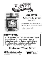
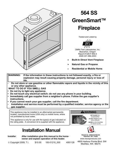
<strong>564</strong> <strong>SS</strong><br />
GreenSmart<br />
<strong>Fireplace</strong><br />
Tested and Listed by<br />
OMNI-Test Laboratories, Inc.<br />
Beaverton, Oregon<br />
Report # 028-F-80b-5<br />
ANSI Z21.88b-2003<br />
• Built-In Direct Vent <strong>Fireplace</strong><br />
• Natural Gas or Propane<br />
• Residential or Mobile Home<br />
WARNING: If the information in these instructions is not followed exactly, a fire or<br />
explosion may result causing property damage, personal injury or loss of<br />
life.<br />
- Do not store or use gasoline or other flammable vapors and liquids in the vicinity of this<br />
or any other appliance.<br />
WHAT TO DO IF YOU SMELL GAS<br />
• Do not try to light any appliance.<br />
• Do not touch any electrical switch; do not use any phone in your building.<br />
• Immediately call gas supplier from a neighbor's phone. Follow the gas supplier's<br />
instructions.<br />
• If you cannot reach your gas supplier, call the fire department.<br />
- Installation and service must be performed by a qualified installer, service agency or the<br />
gas supplier.<br />
This appliance may be installed in an aftermarket permanently<br />
located, manufactured home (USA only) or mobile home, where<br />
not prohibited by local codes.<br />
This appliance is only for use with the type(s) of gas indicated on<br />
the rating plate. A conversion kit is supplied with the appliance.<br />
Installation Manual<br />
Installer: After installation give this manual to the homeowner<br />
and explain operation of this heater.<br />
© Copyright 2009, T.I. $10.00 100-01210_000 4081126<br />
www.travisproducts.com<br />
4800 Harbour Pointe Blvd. SW<br />
Mukilteo, WA 98275
2 Introduction<br />
Overview<br />
This manual details the installation requirements<br />
for the <strong>564</strong> GS fireplace. For operating and<br />
maintenance instructions, refer to the <strong>564</strong> GS<br />
Owner's Manual (part # 100-01211).<br />
Listing Details<br />
This appliance was listed by OMNI Test Labs to<br />
ANSI Z21.88 - report # 028-F-80b-5. The listing<br />
label is attached to the appliance near the gas<br />
control valve. A copy is shown to the right.<br />
IAS (ICBO) Approval<br />
This appliance was listed by OMNI Test Labs - IAS<br />
# TL130.<br />
Massachusetts Approval<br />
This manual has been submitted to the<br />
Massachusetts Board of State Examiners of<br />
Plumbers and Gas Fitters<br />
National <strong>Fireplace</strong> Institute<br />
© Travis Industries 4081126 100-01210_000
Introduction<br />
Overview ............................................................................. 2<br />
Listing Details ...................................................................... 2<br />
Safety Precautions<br />
Safety Precautions .............................................................. 4<br />
Features and Specifications<br />
Features .............................................................................. 6<br />
Installation Options .............................................................. 6<br />
Heating Specifications ......................................................... 6<br />
Dimensions ......................................................................... 6<br />
Installation<br />
Packing List ......................................................................... 7<br />
Additional Items Required ................................................... 7<br />
Installation Overview ........................................................... 7<br />
Recommended Installation Procedure ................................ 7<br />
Top Stand-Off Assembly ..................................................... 9<br />
Converting the <strong>Fireplace</strong> to Top Vent Configuration ........... 10<br />
<strong>Fireplace</strong> Placement Requirements .................................... 12<br />
Clearances ...................................................................... 12<br />
Raised <strong>Fireplace</strong>s ............................................................ 12<br />
Min. Framing Dims. - Rear Vent Configuration ........................... 13<br />
Min. Framing Dims. - Top Vent Configuration ................. 14<br />
Nailing Brackets .............................................................. 15<br />
Corner Installations - Rear Vent Configuration ................ 16<br />
Corner Installations - Top Vent Configuration .................. 17<br />
Gas Line Requirements ...................................................... 18<br />
Fuel ................................................................................. 18<br />
Gas Line Connection ....................................................... 18<br />
Gas Inlet Pressure ........................................................... 18<br />
Gas Line Location............................................................ 18<br />
Electrical Connection (required) .......................................... 20<br />
Optional Wall Switch or Thermostat Installation .................. 21<br />
Vent Requirements ............................................................. 22<br />
Vent Clearances .............................................................. 22<br />
Altitude Considerations .................................................... 22<br />
Approved Vent ................................................................. 23<br />
Vent Installation ............................................................... 23<br />
Approved Vent Configurations ............................................ 24<br />
Restrictor Position ........................................................... 24<br />
Exhaust Restrictor Adjustment ........................................ 24<br />
Intake Restrictor Adjustment ........................................... 25<br />
Diffuser Plate Adjustment ................................................ 26<br />
Rear Vent Config. W Horizontal Term. (no vertical rise) ..... 27<br />
Rear Vent Config. W Horizontal Term. (w vertical rise) ....... 28<br />
Rear Vent Configuration with Vertical Termination .............. 29<br />
Top Vent Configuration with Horizontal Termination ........... 30<br />
Top Vent Configuration with Vertical Termination ............... 31<br />
Termination Requirements .................................................. 32<br />
Table of Contents 3<br />
Installation (continued)<br />
Hearth Requirements .......................................................... 33<br />
Facing Requirements .......................................................... 34<br />
Drywall Installation .......................................................... 34<br />
Facing Overview ............................................................. 35<br />
Optional Faceplates – Sizing Chart ................................. 35<br />
Thin Facing Installation ................................................... 36<br />
Thick Facing Installation .................................................. 38<br />
Thick Facing Installation with FPX Arched Faces............ 39<br />
Mantel Requirements .......................................................... 41<br />
Install Example - Build-Out (Dog-House) w Hor. Term. ...... 42<br />
Install Example - Build-In w Hor. Term. ............................... 43<br />
Finalizing the Installation<br />
Steps for Finalizing the Installation ..................................... 44<br />
Air Shutter Adjustment .................................................... 45<br />
Glass Frame Removal and Installation ............................... 46<br />
Log Set Installation ............................................................. 48<br />
LP Conversion Instructions ................................................. 55<br />
Optional Equipment<br />
Fireback Installation ............................................................ 58<br />
Grill Installation ................................................................... 59<br />
GreenSmart Remote Control Installation ......................... 60<br />
Index<br />
Index ................................................................................... 72<br />
© Travis Industries 4081126 100-01210_000
4 Safety Precautions<br />
Safety Warnings:<br />
• Failure to follow all of the requirements may result in property damage, bodily injury, or even death.<br />
• This unit must be installed by a qualified installer to prevent the possibility of an explosion.<br />
• This appliance must be installed in accordance with all local codes, if any; if not, in U.S.A. follow<br />
ANSI Z223.1 and NFPA 54(88).<br />
• A manufactured home (USA only) or mobile home OEM installation must conform with the<br />
Manufactured Home Construction and Safety Standard, Title 24 CFR, Part 3280, or, when such a<br />
standard is not applicable, the Standard for Manufactured Home Installations, ANSI/NCSBCS<br />
A225.1, or Standard for Gas Equipped Recreational Vehicles and Mobile Housing, CSA Z240.4. This<br />
appliance may be installed in Manufactured Housing only after the home is site located.<br />
• All exhaust gases must be vented outside the structure of the living-area. Combustion air is drawn<br />
from outside the living-area structure. The venting must not be connected to a chimney flue serving a<br />
separate solid-fuel burning appliance.<br />
• Notify your insurance company before hooking up this fireplace.<br />
• The room heater should be inspected before use and at least annually by a qualified service person.<br />
More frequent cleaning may be required due to excessive lint from carpeting, bedding material, etc.<br />
• The instructions in this manual must be strictly adhered to. Do not use makeshift methods or<br />
compromise in the installation. Improper installation will void the warranty and safety listing.<br />
• This heater is approved for use with natural gas (NG) or propane (LP). Burning the incorrect fuel will<br />
void the warranty and safety listing and may cause an extreme safety hazard. Direct questions about<br />
the type of fuel used to your dealer. Check the label and flame adjust knob on the gas control valve.<br />
• Contact your local building officials to obtain a permit and information on any installation restrictions<br />
or inspection requirements in your area.<br />
• If the flame becomes sooty, dark orange in color, or extremely tall, do not operate the heater. Call<br />
your dealer and arrange for proper servicing.<br />
• It is imperative that control compartments, screens, or circulating air passageways of the heater be<br />
kept clean and free of obstructions. These areas provide the air necessary for safe operation.<br />
• Do not operate the heater if it is not operating properly in any fashion or if you are uncertain. Call<br />
your dealer for a full explanation of your heater and what to expect.<br />
• Do not store or use gasoline or other flammable liquids in the vicinity of this heater.<br />
• Do not operate if any portion of the heater was submerged in water or if any corrosion occurs.<br />
• Do not place clothing or other flammable items on or near the heater. Because this heater can be<br />
controlled by a thermostat there is a possibility of the heater turning on and igniting any items placed<br />
on or near it.<br />
• Light the heater using the built-in igniter. Do not use matches or any other external device to light<br />
your heater.<br />
• Never remove, replace, modify or substitute any part of the heater unless instructions are given in this<br />
manual. All other work must be done by a trained technician. Don't modify or replace orifices.<br />
• The viewing glass should be opened only for conducting service.<br />
• Any safety screen or guard removed for servicing must be replaced prior to operating the heater.<br />
Travis Industries 4081126 100-01210_000
Safety Warnings (continued):<br />
Safety Precautions 5<br />
• Allow the heater to cool before carrying out any maintenance or cleaning.<br />
• Operate the heater according to the instructions included in this manual.<br />
• If the main burners do not start correctly turn the gas off and call your dealer for service.<br />
• This unit is not for use with solid fuel.<br />
• Do not place anything inside the firebox (except the included fiber logs).<br />
• If the fiber logs become damaged, replace with Travis Industries log set.<br />
• Do not throw this manual away. This manual has important operating and maintenance instructions<br />
that you will need at a later time. Always follow the instructions in this manual.<br />
• Do not touch the hot surfaces of the heater. Educate all children of the danger of a high-temperature<br />
heater. Young children should be supervised when they are in the same room as the heater.<br />
• Due to the high temperature, the heater should be located out of traffic and away from furniture and<br />
draperies.<br />
• Instruct everyone in the house how to shut gas off to the appliance and at the gas main shutoff valve.<br />
The gas main shutoff valve is usually next to the gas meter or propane tank and requires a wrench to<br />
shut off.<br />
• Travis Industries, Inc. grants no warranty, implied or stated, for the installation or<br />
maintenance of your heater, and assumes no responsibility of any consequential damage(s).<br />
© Travis Industries 4081126 100-01210_000
6 Features and Specifications<br />
Installation Options<br />
• Residential or Mobile Home<br />
• Straight or Corner Placement<br />
• Flush or Recessed Face<br />
Heating Specifications<br />
• Raised or Floor Placement<br />
• Internal or External Chase<br />
• Horizontal or Vertical Vent<br />
• Bedroom Approved<br />
Natural Gas Propane<br />
Approximate Heating Capacity (in square feet)* 950 950<br />
Maximum BTU Input Per Hour 20,500 20,500<br />
* Heating capacity will vary with floor plan, insulation, and outside temperature.<br />
** Efficiency rating is a product thermal efficiency rating determined under continuous operation<br />
independent of installed system.<br />
Dimensions<br />
30"*<br />
762mm<br />
16-1/4"*<br />
413mm<br />
Top Vent Configuration<br />
8" (203mm) Diameter Vent 4-3/4"<br />
121mm<br />
31-3/4"<br />
794mm<br />
* Includes the required 1/2" (13mm)<br />
clearance.<br />
<br />
<br />
<br />
<br />
<br />
<br />
18-3/4"<br />
32-1/2"<br />
476mm<br />
<br />
826mm<br />
<br />
<br />
<br />
<br />
<br />
36-1/4"<br />
<br />
921mm<br />
Left<br />
28-3/4"<br />
730mm<br />
30-1/4"<br />
768mm<br />
1"<br />
25mm<br />
33-1/4"<br />
845mm<br />
Rear Vent Configuration<br />
8" (203mm) Diameter Vent<br />
Back of <strong>Fireplace</strong><br />
24-1/4"<br />
616mm<br />
Weight: 155 Lbs. (70.4kg)<br />
Travis Industries 4081126 100-01210_000<br />
Front<br />
Right
Packing List<br />
• Propane Conversion Kit<br />
• Log Set<br />
• Firestop (sku 250-00747)<br />
Additional Items Required<br />
Installation (for qualified installers only) 7<br />
• Direct Vent<br />
• Gas Line Equipment (shutoff valve, pipe, etc.)<br />
• Electrical Equipment (min. 14 gauge, grounded line)<br />
Installation Overview<br />
• All requirements below must be met.<br />
Top Vent<br />
Configuration<br />
See the section<br />
"Mantel Requirements"<br />
Side<br />
Wall<br />
See "Optional Non-<br />
Combustible Facing"<br />
<br />
<br />
<br />
<br />
<br />
<br />
<br />
<br />
<br />
<br />
Drywall<br />
<br />
<br />
<br />
<br />
<br />
<br />
<br />
<br />
<br />
<br />
Drywall<br />
<br />
<br />
1" Min.<br />
25mm<br />
See "Optional Non-<br />
Combustible Hearth"<br />
See the section<br />
"Electrical Connection"<br />
Recommended Installation Procedure<br />
See the section<br />
"Vent Requirements"<br />
See the section<br />
"Approved Vent<br />
Configurations"<br />
Insulation must not fill<br />
the 1/2" (13mm)<br />
clearance around the<br />
back and sides of the<br />
fireplace.<br />
Nailing Brackets<br />
See the section "Minimum<br />
Framing Dimensions"<br />
See the section<br />
"Gas Line Installation"<br />
Rear Vent<br />
Configuration<br />
• Frame the opening for the fireplace. Make sure to allow for vent installation.<br />
• This fireplace is designed to accommodate 1/2" (13mm) or 5/8" (16mm) drywall (see "Nailing<br />
Brackets" on page 15 for details). Secure the fireplace to the framing.<br />
• Install the vent, gas line and electrical hook-up.<br />
• Install the drywall.<br />
• Install the hearth (if applicable).<br />
• Install the facing (if applicable).<br />
• Install the mantel (if applicable).<br />
• Finalize the installation (see page 44) and install the grill or face.<br />
Required Travis<br />
Firestop (sku<br />
250-00747)<br />
© Travis Industries 4081126 100-01210_000
8 Installation (for qualified installers only)<br />
Massachusetts Requirements<br />
NOTE: The following requirements reference various Massachusetts and national codes not contained in this document.<br />
Requirements for the Commonwealth of Massachusetts<br />
For all side wall horizontally vented gas fueled equipment installed in every dwelling, building or structure used in whole or in<br />
part for residential purposes, including those owned or operated by the Commonwealth and where the side wall exhaust vent<br />
termination is less than seven (7) feet above finished grade in the area of the venting, including but not limited to decks and<br />
porches, the following requirements shall be satisfied:<br />
Installation of Carbon Monoxide Detectors<br />
At the time of installation of the side wall horizontal vented gas fueled equipment, the installing plumber or gasfitter shall<br />
observe that a hard wired carbon monoxide detector with an alarm and battery back-up is installed on the floor level where the<br />
gas equipment is to be installed. In addition, the installing plumber or gasfitter shall observe that a battery operated or hard<br />
wired carbon monoxide detector with an alarm is installed on each additional level of the dwelling, building or structure served<br />
by the side wall horizontal vented gas fueled equipment. It shall be the responsibility of the property owner to secure the<br />
services of qualified licensed professionals for the installation of hard wired carbon monoxide detectors.<br />
In the event that the side wall horizontally vented gas fueled equipment is installed in a crawl space or an attic, the hard wired<br />
carbon monoxide detector with alarm and battery back-up may be installed on the next adjacent floor level.<br />
In the event that the requirements of this subdivision can not be met at the time of completion of installation, the owner shall<br />
have a period of thirty (30) days to comply with the above requirements; provided, however, that during said thirty (30) day<br />
period, a battery operated carbon monoxide detector with an alarm shall be installed.<br />
Approved Carbon Monoxide Detectors<br />
Each carbon monoxide detector as required in accordance with the above provisions shall comply with NFPA 720 and be<br />
ANSI/UL 2034 listed and IAS certified.<br />
Signage<br />
A metal or plastic identification plate shall be permanently mounted to the exterior of the building at a minimum height of eight<br />
(8) feet above grade directly in line with the exhaust vent terminal for the horizontally vented gas fueled heating appliance or<br />
equipment. The sign shall read, in print size no less than one-half (1/2) inch in size, “GAS VENT DIRECTLY BELOW. KEEP<br />
CLEAR OF ALL OBSTRUCTIONS”.<br />
Inspection<br />
The state or local gas inspector of the side wall horizontally vented gas fueled equipment shall not approve the installation<br />
unless, upon inspection, the inspector observes carbon monoxide detectors and signage installed in accordance with the<br />
provisions of 248 CMR 5.08(2)(a)1 through 4.<br />
Exemptions<br />
The following equipment is exempt from 248 CMR 5.08(2)(a)1 through 4:<br />
• The equipment listed in Chapter 10 entitled “Equipment Not Required To Be Vented” in the most current edition of NFPA 54<br />
as adopted by the Board; and<br />
• Product Approved side wall horizontally vented gas fueled equipment installed in a room or structure separate from the<br />
dwelling, building or structure used in whole or in part for residential purposes.<br />
MANUFACTURER REQUIREMENTS<br />
Gas Equipment Venting System Provided<br />
When the manufacturer of Product Approved side wall horizontally vented gas equipment provides a venting system design or<br />
venting system components with the equipment, the instructions provided by the manufacturer for installation of the equipment<br />
and the venting system shall include:<br />
• Detailed instructions for the installation of the venting system design or the venting system components; and<br />
• A complete parts list for the venting system design or venting system.<br />
Gas Equipment Venting System NOT Provided<br />
When the manufacturer of a Product Approved side wall horizontally vented gas fueled equipment does not provide the parts<br />
for venting the flue gases, but identifies “special venting systems”, the following requirements shall be satisfied by the<br />
manufacturer:<br />
• The referenced “special venting system” instructions shall be included with the appliance or equipment installation<br />
instructions; and<br />
• The “special venting systems” shall be Product Approved by the Board, and the instructions for that system shall include a<br />
parts list and detailed installation instructions.<br />
A copy of all installation instructions for all Product Approved side wall horizontally vented gas fueled equipment, all venting<br />
instructions, all parts lists for venting instructions, and/or all venting design instructions shall remain with the appliance or<br />
equipment at the completion of the installation.<br />
See Gas Connection section for additional Commonwealth of Massachusetts requirements.<br />
Travis Industries 4081126 100-01210_000
Top Stand-Off Assembly<br />
Installation (for qualified installers only) 9<br />
The top stand-offs must be assembled prior to installation.<br />
Warning: You must follow the instructions below to elevate both standoffs. Failure to<br />
do so will result in an extreme fire hazard.<br />
AFTER<br />
BEFORE<br />
Standoff<br />
<br />
<br />
<br />
<br />
<br />
<br />
<br />
<br />
<br />
<br />
<br />
The standoffs are shipped in the flat position.<br />
Make sure to follow the instructions below before<br />
installing the fireplace.<br />
© Travis Industries 4081126 100-01210_000<br />
a<br />
b<br />
c<br />
1<br />
Bend the standoff in the numbered<br />
sequence shown above.<br />
2<br />
Remove the screw below the standoff.<br />
Replace the screw to secure the standoff.<br />
3<br />
1/4" Nutdriver
10 Installation (for qualified installers only)<br />
Top Vent or Rear Vent Configuration<br />
This appliance is shipped in the rear vent configuration. To change to the top vent configuration, follow<br />
the directions below.<br />
NOTE: the vent configuration affects several aspects of installation (framing, maximum vent rise,<br />
maximum vent run). Make sure the vent configuration is correct prior to installation. You may wish to<br />
configure the diffuser when changing the vent configuration.<br />
Converting the <strong>Fireplace</strong> to Top Vent Configuration<br />
Remove and discard the<br />
heat shield. Replace the 4<br />
removed screws.<br />
Top of <strong>Fireplace</strong><br />
Remove the 4 screws securing the<br />
intake cover plate. Place the screws<br />
and cover plate aside.<br />
Back of <strong>Fireplace</strong><br />
<br />
<br />
<br />
NOTE: Use a magnetic-tipped<br />
nutdriver on these screws - take<br />
care to prevent the screws from<br />
falling into the fireplace.<br />
Remove the 4 screws securing the<br />
outer flue assembly. Place the<br />
screws and assembly aside.<br />
<br />
<br />
<br />
<br />
<br />
<br />
<br />
Remove the 4 screws securing the<br />
inner flue assembly. Place the<br />
screws and assembly aside.<br />
Remove and discard the<br />
insulation found below the<br />
large cover plate.<br />
Travis Industries 4081126 100-01210_000
Installation (for qualified installers only) 11<br />
Converting the <strong>Fireplace</strong> to Top Vent (continued)<br />
Remove the 4 screws securing the<br />
exhaust cover plate. Verify the gasket<br />
on the cover plate is in place, then<br />
attach it to the rear-facing exhaust<br />
port with the same screws.<br />
Verify the gasket on the inner flue<br />
assembly is in place, then attach it to<br />
the upward-facing exhaust port using<br />
the screws removed earlier.<br />
Verify the gasket on the intake cover<br />
plate is in place, then attach it to the<br />
rear of the fireplace using the screws<br />
removed earlier.<br />
Verify the gasket on the outer flue<br />
assembly is in place, then attach it to<br />
the top of the fireplace using the<br />
screws removed earlier.<br />
© Travis Industries 4081126 100-01210_000
12 Installation (for qualified installers only)<br />
<strong>Fireplace</strong> Placement Requirements<br />
• The fireplace requires a 1/2" (13mm) clearance from the angled sides and back of the fireplace to the<br />
framing members. No material (insulation, framing, etc.) may be placed into this area.<br />
• <strong>Fireplace</strong> must be installed on a level surface capable of supporting the fireplace and vent<br />
• <strong>Fireplace</strong> must be placed directly on wood or non-combustible surface (not on linoleum or carpet)<br />
• This heater may be placed in a bedroom. Please be aware of the large amount of heat this appliance<br />
produces when determining a location.<br />
Clearances<br />
• When installed, walls in front of the fireplace must be a minimum 1" (25mm) to the side of the<br />
fireplace.<br />
• Due to the high temperature, the heater should be located out of traffic and away from furniture and<br />
draperies.<br />
• <strong>Fireplace</strong> must be placed so the vents below and above the glass do not become blocked.<br />
Raised <strong>Fireplace</strong>s<br />
• The fireplace (and hearth, if desired) may be placed on a platform designed to support the fireplace<br />
(155 Lbs.70 Kg) and vent.<br />
Travis Industries 4081126 100-01210_000
Installation (for qualified installers only) 13<br />
Minimum Framing Dimensions - Rear Vent Configuration<br />
HINT: place the fireplace so the center<br />
line is at least 5" (127mm) from both<br />
vertical framing members at the rear (this<br />
allows the vent to pass through the<br />
framing without modfications)<br />
Minimum 38" (965mm)<br />
<strong>Fireplace</strong> Enclosure Height<br />
Route the<br />
electrical line to<br />
a position to the<br />
left rear of the<br />
fireplace.<br />
33-1/2"<br />
851mm<br />
36-1/2"<br />
927mm<br />
Included Firestop (required)<br />
Part # 250-00747<br />
<br />
<br />
<br />
<br />
<br />
<br />
<br />
<br />
32-1/2"<br />
<br />
<br />
<br />
19-1/4"<br />
489mm<br />
Vent Clearances for 8" (203mm) dia. Vent:<br />
1" (25mm) to the sides, 1" (25mm) below,<br />
and 4" (102mm) above the vent to<br />
combustibles.<br />
826mm<br />
16-1/2"<br />
419mm<br />
Center of Rear Vent<br />
24-1/4"<br />
616mm<br />
The on/off switch/thermostat wire (if<br />
used) should be routed to a location<br />
near the right front of the fireplace.<br />
© Travis Industries 4081126 100-01210_000
14 Installation (for qualified installers only)<br />
Minimum Framing Dimensions - Top Vent Configuration<br />
Route the electrical line to<br />
a position to the left rear<br />
of the fireplace.<br />
33-1/2"<br />
851mm<br />
36-1/2"<br />
927mm<br />
Minimum enclosure height = 36-1/4" (921mm)<br />
16-1/2"<br />
419mm<br />
WARNING: A cut-out for the gas line<br />
may be required on the framing. See<br />
the dimensions under "Gas Line<br />
Connection" for details.<br />
The on/off switch/thermostat wire (if<br />
used) should be routed to a location<br />
near the right front of the fireplace.<br />
Travis Industries 4081126 100-01210_000
Nailing Brackets<br />
There are four nailing brackets<br />
on the front of the fireplace.<br />
Follow the directions below to<br />
prepare the nailing brackets.<br />
Once in place, nail or screw the<br />
nailing brackets to the framing.<br />
NOTE: Additional nailing<br />
brackets are provided along<br />
the base of the fireplace.<br />
Use these brackets if not<br />
using the front brackets.<br />
1/2" (13mm)<br />
Drywall<br />
For installations using<br />
1/2" (13mm) facing fold<br />
the larger tab out 90°<br />
(use a screwdriver if<br />
necessary).<br />
5/8" (0.625mm) Drywall<br />
For installations using<br />
5/8" (0.625mm) drywall<br />
fold the shorter tab out<br />
90° (use a screwdriver if<br />
necessary).<br />
Installation (for qualified installers only) 15<br />
TOP VIEW<br />
<strong>Fireplace</strong><br />
TOP VIEW<br />
<strong>Fireplace</strong><br />
WARNING:<br />
Make sure the fireplace is<br />
square and plumb when<br />
placed in the framing.<br />
Measured corner-tocorner,<br />
the fireplace<br />
should be square (approx.<br />
47-1/8" (1197mm) for each<br />
dimension). Use shims to<br />
insure the fireplace is<br />
square.<br />
Framing<br />
Drywall<br />
<br />
<br />
<br />
<br />
Nailing Bracket<br />
Framing<br />
Nailing Bracket<br />
Drywall<br />
© Travis Industries 4081126 100-01210_000
16 Installation (for qualified installers only)<br />
Corner Installations - Rear Vent Configuration<br />
A typical 45° installation uses the framing dimensions shown in the illustration below (NOTE: all<br />
clearances still apply).<br />
7" (178mm)<br />
Approximate<br />
(varies due to vent<br />
installation)<br />
NOTE: Most installations<br />
use:<br />
6" (152mm) Section for 2x6<br />
(51mm X 152mm) Walls<br />
4" (102mm) Section for 2x4<br />
(51mm X 102mm) Walls<br />
44-1/2" Min.<br />
1130mm<br />
Minimum 1" (25mm)<br />
Clearance<br />
<br />
<br />
<br />
<br />
<br />
<br />
<br />
<br />
<br />
<br />
<br />
<br />
<br />
<br />
<br />
<br />
<br />
<strong>564</strong> <strong>SS</strong> Firestop<br />
Minimum 1/2" (13mm)<br />
Clearance<br />
<br />
<br />
<br />
<br />
<br />
<br />
<br />
<br />
<br />
<br />
<br />
<br />
<br />
<br />
Travis Industries 4081126 100-01210_000
Installation (for qualified installers only) 17<br />
Corner Installations - Top Vent Configuration<br />
A typical 45° installation uses the framing dimensions shown in the illustration below (NOTE: all<br />
clearances still apply).<br />
44-1/2" Min.<br />
1130mm<br />
14-1/4"<br />
362mm<br />
Minimum 1/2" (13mm)<br />
Clearance<br />
<br />
<br />
<br />
<br />
<br />
<br />
<br />
<br />
<br />
<br />
<br />
<br />
<br />
<br />
<br />
<br />
<br />
<br />
<br />
<br />
<br />
<br />
<br />
<br />
<br />
<br />
<br />
<br />
<br />
<br />
<br />
<br />
© Travis Industries 4081126 100-01210_000
18 Installation (for qualified installers only)<br />
Gas Line Requirements<br />
Fuel<br />
MA<strong>SS</strong>ACHUSETTS INSTALLATIONS - WARNING:<br />
THIS PRODUCT MUST BE INSTALLED BY A LICENSED PLUMBER OR GAS FITTER WHEN INSTALLED WITHIN THE<br />
COMMONWEALTH OF MA<strong>SS</strong>ACHUSETTS.<br />
OTHER MA<strong>SS</strong>ACHUSETTS CODE REQUIREMENTS:<br />
• Flexible connector must not be longer than 36 inches.<br />
• Shutoff valve must be a “T” handle gas cock.<br />
• Only direct vent sealed combustion products are approved for bedrooms or bathrooms.<br />
• <strong>Fireplace</strong> dampers must be removed or welded in the open position prior to the installation of a fireplace insert or gas log.<br />
• A carbon monoxide (CO) detector is required in the same room as the appliance.<br />
• The gas line must be installed in accordance with all local codes, if any; if not, follow ANSI 223.1 and<br />
the requirements listed below.<br />
• The fireplace and gas control valve must be disconnected from the gas supply piping during any<br />
pressure testing of that system at test pressures in excess of 1/2 psig. For pressures under 1/2 psig,<br />
isolate the gas supply piping by closing the manual shutoff valve.<br />
• Leak test all gas line joints and the gas control valve prior to and after starting the fireplace.<br />
• This fireplace is designed either for natural gas or for propane (but not for both). Check the sticker on the top of<br />
the gas control valve to make sure the correct fuel is used.<br />
Gas Line Connection<br />
• Installation must be performed by a qualified installer, service agency or the gas supplier (In Massachusetts a<br />
licensed plumber/gasfitter).<br />
Gas Inlet Pressure Standard Input Pressure<br />
Natural Gas 7" W.C. (1.74 kPA)<br />
Propane 13" W.C. (2.73 kPA)<br />
• If the pressure is not sufficient, make sure the piping used is large enough, the supply regulator is adequately<br />
adjusted, and the total gas load for the residence does not exceed the amount supplied.<br />
• The supply regulator (the regulator that attaches directly to the residence inlet or to the propane tank) should<br />
supply gas at the suggested input pressure listed above. Contact the local gas supplier if the regulator is at an<br />
improper pressure.<br />
Travis Industries 4081126 100-01210_000
Gas Line Location<br />
Right Side Gas Inlet (preferred)<br />
A 6" (152mm) flex tube and shutoff<br />
valve is included with the fireplace.<br />
The shutoff valve accepts a 1/2"MPT.<br />
Left Side Gas Inlet<br />
A 3" (76mm) high by 2" (51mm) wide opening is<br />
located behind the gas inlet cover plate. It is 4-3/4"<br />
(121mm) behind the front and 1-3/4" (44mm) above<br />
the base of the fireplace.<br />
You may remove this cover plate to install<br />
the gas line. The cover plate has a 7/8"<br />
(0.875mm) diameter hole (covered with a<br />
push plug). By rotating the plate 180° the<br />
hole may be re-located. You may also<br />
secure the plate in a customized location<br />
using the self-drilling screws.<br />
Installation (for qualified installers only) 19<br />
You may wish to route the flex line along<br />
the front edge of the fireplace to conceal it.<br />
13-3/4"<br />
349mm<br />
A 3" (76mm) high by 2" (51mm) wide opening is<br />
located behind the gas inlet cover plate. It is 7-3/4"<br />
(197mm) behind the front and 1-3/4" (44mm) above<br />
the base of the fireplace.<br />
8-3/4"<br />
222mm<br />
13-3/4"<br />
349mm<br />
The gas inlet is located 2-1/2"<br />
(64mm) above the base of the<br />
fireplace.<br />
You may remove this cover plate to install the gas line. The<br />
cover plate has a 7/8" (.0875mm) diameter hole (covered<br />
with a push plug) in line with the gas inlet on the gas control<br />
valve. By rotating the plate 180° the hole may be re-located.<br />
You may also secure the plate in a customized location using<br />
the self-drilling screws.<br />
A 6" (152mm) flex tube and shutoff valve is<br />
included with the fireplace. You may wish to<br />
use a 24" (610mm) flex tube. The shutoff valve<br />
accepts a 1/2" MPT.<br />
8-3/4"<br />
222mm<br />
© Travis Industries 4081126 100-01210_000
20 Installation (for qualified installers only)<br />
Electrical Connection (required)<br />
• The electrical line to the grounded receptacle inside the fireplace must be installed by a qualified<br />
installer and must meet all local codes.<br />
• Make sure the household breaker is shut off prior to working on any electrical lines.<br />
• The appliance, when installed, must be electrically grounded in accordance with local codes or, in the<br />
absence of local codes, with the National Electrical Code, ANSI/NFPA 70, or the Canadian Electrical<br />
Code, CSA C22.1.<br />
• The electrical line must be a min. 14 gauge, and supply 120 Volts at 60 Hz (2 Amps).<br />
Caution: Label all wires prior to disconnection when servicing controls. Wiring errors can cause<br />
improper and dangerous operation.<br />
a b c d<br />
Travis Industries 4081126 100-01210_000
Installation (for qualified installers only) 21<br />
Optional Wall Switch or Thermostat Installation<br />
Do not connect 110-120 VAC to the gas control valve or wiring system of this fireplace. The switch and<br />
wiring must be installed by a qualified installer.<br />
This fireplace includes an optional wall switch (with wire)<br />
to operate the fireplace burner without accessing the<br />
internal on/off switch. A thermostat may be used instead.<br />
Route the wire from inside the fireplace, through the<br />
grommet on either side of the fireplace near the gas inlet<br />
(see at right) to the switch. The wall switch (or thermostat)<br />
may bypass the fireplace on/off switch or be installed in<br />
parallel or series configuration (see below).<br />
Caution: Label all wires prior to disconnection when<br />
servicing controls. Wiring errors can cause<br />
improper and dangerous operation.<br />
Note: When using a GreenSmart remote, use the<br />
receiver for on/off operation (do not use a wall<br />
switch or thermostat).<br />
Warning: Make sure all wiring is secure and does not<br />
contact hot or moving components.<br />
OPTIONAL WALL SWITCH<br />
(included with fireplace)<br />
Place "WARNING"<br />
label on switch cover.<br />
Parallel Connection Series Connection<br />
Thermostat / External<br />
Switch ON<br />
Thermostat / External<br />
Switch OFF<br />
On / Off Switch On / Off Switch<br />
ON<br />
OFF<br />
Heater is ON Heater is ON Thermostat /<br />
External Switch ON<br />
Heater is ON Heater is OFF Thermostat /<br />
External Switch OFF<br />
On / Off Switch<br />
ON<br />
On / Off Switch<br />
OFF<br />
Heater is ON Heater is OFF<br />
Heater is OFF Heater is OFF<br />
To wire the heater in parallel, follow the directions below: To wire the heater in series, follow the directions below:<br />
a b<br />
a<br />
On / Off Switch<br />
c<br />
Thermostat<br />
(or External Switch) Wires<br />
On / Off Switch<br />
© Travis Industries 4081126 100-01210_000<br />
c<br />
b<br />
Thermostat<br />
(or External Switch) Wires
22 Installation (for qualified installers only)<br />
Vent Requirements<br />
• The gas appliance and vent system must be vented directly to the outside of the building, and never<br />
be attached to a chimney serving a separate solid fuel or gas-burning appliance. Each direct vent<br />
gas appliance must use it's own separate vent system.<br />
• In addition to the requirements listed here, follow the requirements provided with the vent.<br />
• A firestop is required whenever the vent penetrates a wall, floor, or ceiling (passes through framing<br />
members). Horizontal vent less than 48" (1219mm) above the fireplace must use the Travis Firestop<br />
(sku 250-00747 - it incorporates a 4" (102mm) clearance above, 1"( 25mm)clearance below and to<br />
the sides of the vent). Other penetrations only require a 1" (25mm) clearance and may use a<br />
standard firestop (make sure the required 1" (25mm) clearance is met).<br />
• Always use the high-wind termination (if available from the vent manufacturer).<br />
Vent Clearances<br />
• The vent must maintain the required clearance to combustible materials to prevent a fire. Do not fill<br />
air spaces with insulation.<br />
Before 48" (1219mm) After 48" (1219mm)<br />
Rise<br />
Rise<br />
Sides 1" (25mm) 1" (25mm)<br />
Above 4" (102mm) 1" (25mm)<br />
Below Horizontal or 45° Section 1" (25mm) 1" (25mm)<br />
Vertical Termination<br />
Use a roof flashing and storm collar<br />
whenever passing through the roof<br />
Use a firestop whenever<br />
passing through a ceiling<br />
Use a support box<br />
on exposed vent<br />
Altitude Considerations<br />
Min. 1"<br />
25mm<br />
Required Firestop<br />
Horizontal<br />
Termination<br />
Min. 4" (102mm)<br />
1" (25mm) if a minimum 48"<br />
(1219mm) above the<br />
fireplace.<br />
Min. 1"<br />
25mm<br />
Travis Industries 4081126 100-01210_000<br />
Min. 1"<br />
25mm<br />
• This heater has been tested at altitudes ranging from sea level to 6,000 feet (1800M). In this testing we have<br />
found that the heater, with its standard orifice, burns correctly with just an air shutter adjustment.<br />
• Failure to adjust the air shutter properly may lead to improper combustion which can create a safety hazard.<br />
Consult your dealer or installer if you suspect an improperly adjusted air shutter.
Approved Vent<br />
Installation (for qualified installers only) 23<br />
• Rear vent configurations use 8" (203mm) diameter Simpson Dura-Vent Model Direct-Vent Pro (or<br />
GS)*.<br />
* Other vent may be approved with this fireplace. Check with the vent manufacturer for details.<br />
• Top vent configurations use 8" (203mm) or 6-5/8" (168mm) diameter Simpson Dura-Vent Direct-Vent<br />
Pro (or GS)*. If using 6-5/8" (168mm) diameter vent, attach the 8" (203mm) to 6-5/8" (168mm)<br />
reducer (Travis part # 98900165) to the fireplace.<br />
NOTE: When using 6-5/8” (168mm) diameter vent, make sure to accommodate the 4” (102mm)<br />
clearance above the vent for the first 48” (1219mm) of rise (see vent clearances on page 22). Standard<br />
firestops do not include this clearance.<br />
• Always use the high-wind cap (or high-wind sconce cap, part # 58DVA-HSCH or 46DVA-HSCH).<br />
• Installation instructions for Simpson Dura-Vent may be found at www.duravent.com<br />
Vent Installation<br />
6-5/8" (168mm) Diameter Vent<br />
Reducer - # 98900165<br />
• Slide the vent sections together and turn 1/4 turn until the sections lock in<br />
place.<br />
• Screws are not required to secure the vent. However, three screws may be<br />
used to secure vent sections together if desired.<br />
• High temperature sealant is recommended at the appliance starter section<br />
connection (use high-temperature silicone or Mill-Pac®).<br />
• If disassembly is required, at time of re-assembly check to see if the vent<br />
creates a tight fit. If it does not, apply high temperature sealant to the joints<br />
of the affected sections.<br />
• Horizontal sections require a 1/4" (6mm) rise every 12" (305mm) of travel<br />
• Horizontal sections require non-combustible support every three feet (e.g.: plumbing tape)<br />
© Travis Industries 4081126 100-01210_000
24 Installation (for qualified installers only)<br />
Approved Vent Configurations<br />
Restrictor Position<br />
• Intake and exhaust restrictors are built into the appliance to adjust the flow rate of intake air and<br />
exhaust gases. Depending upon the vent configuration, you may be required to adjust the restrictor<br />
positions. The charts for acceptable vent configurations detail the correct vent restrictor positions.<br />
Exhaust Restrictor Adjustment<br />
If the diffuser is required to be in position # 2, you may wish to adjust the diffuser while the exhaust<br />
restrictor is removed.<br />
(closed) #6<br />
# 5<br />
# 4<br />
# 3<br />
# 2<br />
# 1<br />
(open - stock position) # 0<br />
Firebox RoofThe exhaust restrictor is shipped<br />
Back Wall of Firebox<br />
in postion # 0. If the restritor is<br />
required in a different postion,<br />
remove the screws, re-position<br />
the restrictor (see the illustration<br />
below), and replace the screws.<br />
In this example, the restrictor is<br />
set in position # 3.<br />
Back of Firebox<br />
Travis Industries 4081126 100-01210_000
Intake Restrictor Adjustment<br />
Installation (for qualified installers only) 25<br />
<br />
<br />
<br />
<br />
<br />
<br />
Position # 1 (open)<br />
1/4"<br />
Socket<br />
Loosen the two screws<br />
holding the intake<br />
restrictor in place..<br />
Position # 2 (closed)<br />
Slide the restrictor down<br />
to the lower position and<br />
tighten the screws.<br />
© Travis Industries 4081126 100-01210_000
26 Installation (for qualified installers only)<br />
Diffuser Plate Adjustment<br />
Certain vent configurations require the diffuser plate to be adjusted (refer to the approved vent<br />
configuration charts for details). Position # 1 is stock (bent). Position # 2 is flattened. See the directions<br />
below to change the diffuser to position #2.<br />
DIFFUSER SIDE VIEW<br />
Before (Stock - Position # 1)<br />
After (Position # 2)<br />
Firebox Roof<br />
Back Wall of Firebox<br />
<br />
<br />
<br />
1/4" Nutdriver<br />
Remove the exhaust<br />
restrictor.<br />
1/4" Nutdriver<br />
Remove the diffuser.<br />
Bend the round portion of the<br />
diffuser so it is flat (position # 2).<br />
Secure the flattened<br />
diffuser plate with the<br />
screws removed earlier.<br />
Replace the exhaust<br />
restrictor (see “Exhaust<br />
Restrictor Adjustment”<br />
for restrictor settings).<br />
Travis Industries 4081126 100-01210_000
Installation (for qualified installers only) 27<br />
Rear Vent Configuration with Horizontal Termination (no vertical rise)<br />
• The termination must fall within the shaded area shown in the chart. Use the indicated restrictor and<br />
diffuser positions.<br />
Optional 45 Elbow<br />
Vent with No 45 Elbow<br />
3 feet<br />
915mm<br />
0 feet<br />
mm<br />
Vent with 1 45 Elbow<br />
3 feet<br />
915mm<br />
0 feet<br />
mm<br />
0 feet<br />
mm<br />
0 feet<br />
mm<br />
See the charts below to<br />
determine maximum vent<br />
2’ (max)<br />
1.2m<br />
4’ (max)<br />
610mm<br />
Termination<br />
-Exhaust Restrictor:<br />
Remove the exhaust restrictor<br />
and replace the screws.<br />
-Intake Restrictor # 1 (stock)<br />
-Diffuser Position # 1 (stock)<br />
-Min. 4" (102mm) Horizontal Section<br />
-Max.48" (1.2m) Horizontal Section(s)<br />
-Exhaust Restrictor:<br />
Remove the exhaust restrictor<br />
and replace the screws.<br />
-Intake Restrictor # 1 (stock)<br />
-Diffuser Position # 1 (stock)<br />
-Min. 4" (102mm) Horizontal Section<br />
-Max. 24" (610mm) Horizontal Section(s)<br />
© Travis Industries 4110420 100-01210_000
28 Installation (for qualified installers only)<br />
Rear Vent Configuration with Horizontal Termination (with vertical rise)<br />
• The termination must fall within the shaded area shown in the chart. Use the indicated restrictor and<br />
diffuser positions.<br />
• Up to four elbows (45° or 90°) may be used.<br />
• Only one horizontal elbow may be used.<br />
22' max (6.7 m)<br />
5 feet (1.5 m)<br />
0 feet<br />
0 feet<br />
<br />
<br />
<br />
<br />
<br />
<br />
Exhaust Restrictor # 5<br />
<br />
<br />
<br />
Intake Restrictor # 2<br />
<br />
<br />
<br />
Diffuser Position # 2<br />
<br />
<br />
<br />
<br />
<br />
<br />
<br />
<br />
<br />
Exhaust Restrictor # 4<br />
<br />
<br />
<br />
Intake Restrictor # 2<br />
<br />
<br />
Diffuser Position # 2<br />
<br />
<br />
<br />
<br />
Exhaust Restrictor # 2<br />
<br />
Intake Restrictor # 1 (stock)<br />
<br />
Diffuser Position # 1 (stock)<br />
<br />
<br />
20 feet (6 m) 20 feet (6 m)<br />
15 feet (4.5 m)<br />
10 feet (3 m)<br />
0 feet<br />
This is considered a horizontal<br />
elbow (it does not matter<br />
whether it turns right or left).<br />
It may be a 90° or 45° elbow.<br />
5 feet (1.5 m)<br />
5 feet (1.5 m)<br />
H2<br />
H1<br />
5 feet (1.5 m)<br />
Travis Industries 4081126 100-01210_000<br />
10 feet (3 m)<br />
10 feet (3 m)<br />
15 feet (4.5 m)<br />
15 feet (4.5 m)<br />
20' max (6 m)<br />
20' max (6 m)<br />
This is considered a<br />
vertical elbow<br />
22' max (6.7 m)<br />
15 feet (4.5 m)<br />
10 feet (3 m)<br />
0 feet<br />
Horizontal length is calculated by adding<br />
both lengths of horizontal run<br />
(Horizontal Length = H1 + H2).
Installation (for qualified installers only) 29<br />
Rear Vent Configuration with Vertical Termination<br />
• The termination must fall<br />
within the shaded area shown<br />
in the chart. Use the<br />
indicated restrictor and<br />
diffuser positions.<br />
• Up to four elbows (45° or 90°)<br />
may be used.<br />
• Only one horizontal elbow<br />
may be used.<br />
This is considered a horizontal<br />
elbow (it does not matter<br />
whether it turns right or left).<br />
It may be a 90° or 45° elbow.<br />
40' max (12m)<br />
35 feet (10.5m)<br />
30 feet (9m)<br />
25 feet (7.5m)<br />
5 feet (1.5m)<br />
0 feet<br />
<br />
<br />
<br />
<br />
<br />
<br />
<br />
<br />
<br />
<br />
<br />
Exhaust Restrictor # 5<br />
Intake Restrictor # 2<br />
<br />
Diffuser Position # 2<br />
<br />
<br />
<br />
<br />
<br />
<br />
<br />
<br />
Exhaust Restrictor # 4<br />
<br />
<br />
<br />
Intake Restrictor # 2<br />
<br />
<br />
<br />
Diffuser Position # 2<br />
<br />
<br />
<br />
Exhaust Restrictor # 2<br />
<br />
<br />
<br />
Intake Restrictor # 2<br />
<br />
<br />
Diffuser Position # 2<br />
<br />
<br />
© Travis Industries 4081126 100-01210_000<br />
0 feet<br />
20 feet (6m) 20 feet (6m)<br />
15 feet (4.5m)<br />
10 feet (3m)<br />
H2<br />
H1<br />
0 feet<br />
5 feet (1.5m)<br />
5 feet (1.5m)<br />
10 feet (3m)<br />
10 feet (3m)<br />
15 feet (4.5m)<br />
15 feet (4.5m)<br />
Horizontal length is calculated by adding<br />
both lengths of horizontal run<br />
(Horizontal Length = H1 + H2).<br />
This is considered a<br />
vertical elbow<br />
20' max (6m)<br />
20' max (6m)<br />
40' max (12m)<br />
35 feet (10.5m)<br />
30 feet (9m)<br />
25 feet (7.5m)<br />
15 feet (4.5m)<br />
10 feet (3m)<br />
5 feet (1.5m)<br />
0 feet
30 Installation (for qualified installers only)<br />
Top Vent Configuration with Horizontal Termination<br />
• The termination must fall within the shaded area shown in the chart. Use the indicated restrictor and<br />
diffuser positions.<br />
• Up to four elbows (45° or 90°) may be used.<br />
• May use 8" (203mm) or 6-5/8" (168mm) diameter vent (see page for 22 details).<br />
• Only one horizontal elbow may be used.<br />
21' max (6.4m)<br />
5 feet (1.5m)<br />
0 feet<br />
0 feet<br />
<br />
<br />
<br />
<br />
<br />
<br />
<br />
<br />
Exhaust Restrictor # 5<br />
<br />
<br />
<br />
<br />
Intake Restrictor # 2<br />
Diffuser Position # 2<br />
<br />
<br />
<br />
<br />
<br />
<br />
<br />
<br />
<br />
<br />
<br />
<br />
Exhaust Restrictor # 4<br />
Intake Restrictor # 2<br />
<br />
<br />
<br />
Diffuser Position # 2<br />
<br />
<br />
<br />
<br />
<br />
Exhaust Restrictor # 2<br />
<br />
Intake Restrictor # 1 (stock)<br />
<br />
Diffuser Position # 1 (stock)<br />
<br />
<br />
<br />
20 feet (6m) 20 feet (6m)<br />
15 feet (4.5m)<br />
10 feet (3m)<br />
0 feet<br />
This is considered a horizontal<br />
elbow (it does not matter<br />
whether it turns right or left).<br />
It may be a 90° or 45° elbow.<br />
5 feet (1.5m)<br />
5 feet (1.5m)<br />
H2<br />
H1<br />
5 feet (1.5m)<br />
Travis Industries 4081126 100-01210_000<br />
10 feet (3m)<br />
10 feet (3m)<br />
15 feet (4.5m)<br />
15 feet (4.5m)<br />
This is considered a<br />
vertical elbow<br />
20' max (6m)<br />
20' max (6m)<br />
21' max (6.4m)<br />
15 feet (4.5m)<br />
10 feet (3m)<br />
0 feet<br />
Horizontal length is calculated by adding<br />
both lengths of horizontal run<br />
(Horizontal Length = H1 + H2).
Installation (for qualified installers only) 31<br />
Top Vent Configuration with Vertical Termination<br />
• The termination must fall<br />
within the shaded area<br />
shown in the chart. Use<br />
the indicated restrictor<br />
and diffuser positions.<br />
• Up to four elbows (45° or<br />
90°) may be used.<br />
• Only one horizontal<br />
elbow may be used.<br />
• May use 8" (203mm) or<br />
6-5/8" (168mm) diameter<br />
vent (see page for 22<br />
details).<br />
This is considered a horizontal<br />
elbow (it does not matter<br />
whether it turns right or left).<br />
It may be a 90° or 45° elbow.<br />
40' max (12m)<br />
35 feet (10.5m)<br />
30 feet (9m)<br />
25 feet (7.5m)<br />
5 feet (1.5m)<br />
0 feet<br />
0 feet<br />
<br />
<br />
<br />
<br />
<br />
<br />
<br />
<br />
<br />
<br />
<br />
<br />
<br />
<br />
<br />
<br />
<br />
<br />
<br />
<br />
<br />
<br />
Exhaust Restrictor # 5<br />
<br />
<br />
Intake Restrictor # 2<br />
<br />
<br />
Diffuser Position # 2<br />
<br />
<br />
<br />
<br />
<br />
<br />
<br />
<br />
<br />
<br />
<br />
<br />
<br />
Exhaust Restrictor # 4<br />
<br />
<br />
<br />
Intake Restrictor # 2<br />
<br />
<br />
<br />
Diffuser Position # 2<br />
<br />
<br />
Exhaust Restrictor # 2<br />
<br />
<br />
Intake Restrictor # 1 (stock)<br />
<br />
20 feet (6m) 20 feet (6m)<br />
15 feet (4.5m)<br />
10 feet (3m)<br />
H2<br />
H1<br />
0 feet<br />
5 feet (1.5m)<br />
© Travis Industries 4081126 100-01210_000<br />
5 feet (1.5m)<br />
5 feet (1.5m)<br />
10 feet (3m)<br />
10 feet (3m)<br />
15 feet (4.5m)<br />
Diffuser Position # 2<br />
15 feet (4.5m)<br />
Horizontal length is calculated by adding<br />
both lengths of horizontal run<br />
(Horizontal Length = H1 + H2).<br />
This is considered a<br />
vertical elbow<br />
20' max (6m)<br />
20' max (6m)<br />
40' max (12m)<br />
35 feet (10.5m)<br />
30 feet (9m)<br />
25 feet (7.5m)<br />
15 feet (4.5m)<br />
10 feet (3m)<br />
0 feet
32 Installation (for qualified installers only)<br />
Termination Requirements<br />
! Venting terminals shall not be recessed into a wall or siding.<br />
A Minimum 9" (229mm) clearance from any door or window<br />
B Minimum 12" (305mm) above any grade, veranda, porch, deck or balcony<br />
C Minimum 1" (25mm) from outside corner walls<br />
NOTE: Clearance in accordance with local installation codes and the requirements<br />
of the gas supplier.<br />
D Minimum 1" (25mm) from inside corner walls<br />
NOTE: Clearance in accordance with local installation codes and the requirements<br />
of the gas supplier.<br />
Roof<br />
Surface<br />
11" Min.<br />
(279mm)<br />
E Minimum 11" (279mm) clearance below unventilated soffits or roof surfaces<br />
Minimum 18" (457mm) clearance below ventilated soffits<br />
Minimum 6" (152mm) clearance below roof eaves<br />
NOTE: Vinyl surfaces require 24" (610mm)<br />
NOTE: Clearance in accordance with local installation codes and the requirements of the gas supplier.<br />
6" Min.<br />
(152mm)<br />
F Minimum 12" (305mm) clearance below a veranda, porch, deck or balcony<br />
NOTE: Permitted only if veranda, porch, deck, or balcony is fully open on a minumum of two sides beneath the floor.<br />
NOTE: Clearance in accordance with local installation codes and the requirements of the gas supplier.<br />
Roof<br />
Eaves<br />
G Minimum 48" (1219mm) clearance from any adjacent building<br />
H Minimum 84" (2134mm) clearance above any grade when adjacent to public walkways or driveways<br />
NOTE: may not be used over a walkway or driveway shared by an adjacent building<br />
I Minimum 9" (229mm) clearance to any nonmechanical air supply inlet to the building or the combustion air inlet<br />
to any other appliance.<br />
J Minimum 36" (914mm) clearance above any mechanical air supply inlet if within 10’ (3M) horizontally<br />
K Minimum 36" (914mm) from the area above the meter/regulator (vent outlet) - this extends 15’ (4.5M) above the regulator<br />
NOTE: Clearance in accordance with local installation codes and the requirements of the gas supplier.<br />
L Minimum 36" (914mm) from the meter/regulator (vent outlet)<br />
NOTE: Clearance in accordance with local installation codes and the requirements of the gas supplier.<br />
M Minimum 12” (305mm) above the roof line (for vertical terminations)<br />
N Minimum 24” (610mm) horizontal clearance to any surface (such as an exterior wall) – for vertical terminations<br />
G<br />
F<br />
D<br />
N<br />
A<br />
E<br />
E<br />
A<br />
K J<br />
NOTE: Measure clearances to the nearest edge of the exhaust hood.<br />
• Use the vinyl siding standoff when installing on an exterior with vinyl siding.<br />
• Vent termination must not be located where it will become plugged by snow or other material<br />
M<br />
L<br />
Travis Industries 4081126 100-01210_000<br />
C<br />
B<br />
I<br />
E<br />
H
Hearth Requirements<br />
Installation (for qualified installers only) 33<br />
Do not build a hearth more<br />
than 1" (25mm) above the<br />
baseplate (this area must<br />
remain clear for the access<br />
door).<br />
Floor Mounted<br />
<strong>Fireplace</strong>s<br />
<br />
<br />
<br />
<br />
<br />
<br />
<br />
<br />
<br />
<br />
<br />
<br />
<br />
<br />
<br />
<br />
<br />
<br />
<br />
<br />
<br />
<br />
<br />
<br />
<br />
<br />
<br />
<br />
WARNING:<br />
<br />
<br />
<br />
Raised<br />
<strong>Fireplace</strong>s<br />
surface.<br />
<br />
<br />
<br />
<br />
<br />
<br />
<br />
<br />
<br />
<br />
<br />
<br />
<br />
<br />
<br />
<br />
<br />
<br />
<br />
<br />
<br />
<br />
<br />
<br />
<br />
<br />
<br />
<br />
<br />
<br />
<br />
<br />
<br />
<br />
<br />
<br />
<br />
<br />
<br />
<br />
<br />
<br />
<br />
<br />
<br />
<br />
<br />
<br />
<br />
<br />
<br />
<br />
<br />
<br />
<br />
<br />
<br />
<br />
<br />
<strong>Fireplace</strong> Stand<br />
If installed near carpet or other<br />
combustible flooring, the fireplace<br />
must be raised so the base of the<br />
unit is above the carpet surface or<br />
flooring material.<br />
A non-combustible hearth is not required. However, if<br />
the heater is installed next to the floor, we recommend<br />
a hearth to protect the flooring surface from<br />
discoloration or other negative impact from the heater.<br />
A hearth is not required<br />
when the fireplace is<br />
raised above the flooring<br />
© Travis Industries 4081126 100-01210_000
34 Installation (for qualified installers only)<br />
Facing Requirements<br />
• This appliance is designed to allow for drywall (or other combustible facing) to contact the sides and<br />
top of the front of the fireplace.<br />
• Tile or other non-combustible facing may be placed on the front of the fireplace (see "Facing<br />
Overview" on page 35 for further details).<br />
Drywall Installation<br />
Drywall Installation Drywall may be<br />
installed up to the front edge of the fireplace.<br />
If the fireplace is raised, drywall up to the<br />
bottom edge as well.<br />
Do not install drywall (or any<br />
other combustible) in front<br />
of the fireplace.<br />
TOP VIEW<br />
<strong>Fireplace</strong><br />
Framing<br />
Drywall<br />
Drywall<br />
<br />
<br />
Nailing Bracket<br />
Travis Industries 4081126 100-01210_000
Facing Overview<br />
Installation (for qualified installers only) 35<br />
Upgrade faces are available for this fireplace and may influence facing installation. Consult with your<br />
Travis Dealer if you are using an upgrade face.<br />
Optional non-combustible facing may be installed on the fireplace. Use the guidelines below to determine<br />
the location (also see the following pages for detailed diagrams.<br />
Tile Line Any non-combustible facing under 1" (25mm) thick (see "Thin Facing" on page 36).<br />
Masonry Line Any non-combustible over 1" (25mm) thick (see "Thick Facing" on page 38).<br />
Hearth Line Non-combustible hearth/facing should be installed up to this location (1" (25mm) above the base<br />
of the fireplace). The fireplace may be raised to accommodate thicker hearth materials.<br />
Masonry Line<br />
Tile Line<br />
Hearth Line<br />
Masonry Line<br />
Tile Line<br />
Tile Line<br />
Masonry Line<br />
Optional Faceplates – Sizing Chart<br />
<br />
<br />
<br />
<br />
<br />
<br />
<br />
<br />
<br />
<br />
<br />
<br />
<br />
<br />
<br />
Masonry Line<br />
Hearth Line<br />
© Travis Industries 4081126 100-01210_000<br />
Tile Line<br />
Masonry Line<br />
Tile Line<br />
Masonry Line<br />
Tile Line<br />
NOTE: The hearth or facing can extend no<br />
greater than 1'' (25mm) above the base of the<br />
fireplace. The fireplace may be raised to<br />
accommodate thicker hearth materials.<br />
Name Height Width Notes<br />
FPX Art., Clsc., Fr Ctry 29” (737mm) 36” (914mm) 61” Radius – May fit over top of tile facing<br />
Wilmington 29” (737mm) 36” (914mm) May fit over top of tile facing<br />
Victorian Lace 27-1/2” (699mm) 32-3/8” (822mm) Optional facing buttes to edge of faceplate (tile line)<br />
Bungalow, Tree of Life 27-1/2” (699mm) 32-3/8” (822mm) Optional facing buttes to edge of faceplate (tile line)
36 Installation (for qualified installers only)<br />
Thin Facing Installation (tile, marble, or other non-combustible under 1" (25mm) thick)<br />
Upgrade faces are available for this fireplace and may influence facing installation. Consult with your<br />
Travis Dealer if you are using an upgrade face.<br />
Do not install tile (or other material)<br />
in front of the glass frame,<br />
convection channel, or access panel<br />
openings. This area must remain<br />
open to access internal components<br />
and for convection air.<br />
TOP VIEW<br />
<strong>Fireplace</strong><br />
Framing<br />
<br />
<br />
Tile<br />
Facing is installed to this<br />
edge of the fireplace.<br />
NOTE FOR FPX FACES:<br />
FPX arched faces require the FPX Face Upgrade<br />
Kit (sku 98500683) and a triangular piece of<br />
facing in these upper corners. See the<br />
instructions included with the<br />
7-1/2"<br />
face for further<br />
details.<br />
191mm<br />
1-5/8"<br />
41mm<br />
Nailing Bracket<br />
Drywall<br />
<br />
<br />
<br />
<br />
<br />
<br />
<br />
<br />
<br />
<br />
<br />
<br />
<br />
<br />
<br />
<br />
<br />
<br />
<br />
<br />
<br />
<br />
<br />
<br />
<br />
<br />
<br />
<br />
<br />
<br />
<br />
<br />
<br />
<br />
<br />
<br />
<br />
<br />
<br />
<br />
<br />
<br />
<br />
<br />
<br />
<br />
<br />
<br />
Floor-Mounted <strong>Fireplace</strong>s or Raised Hearths:<br />
Build the hearth 1" max (25mm) above the<br />
base of the fireplace. The fireplace may be<br />
Raised <strong>Fireplace</strong>s: raised to accommodate thicker hearth materials.<br />
Facing is installed 1" maximum<br />
(25mm) above the base of the<br />
fireplace.<br />
FRONT VIEW<br />
32-1/2"<br />
826mm<br />
Travis Industries 4081126 100-01210_000<br />
Drywall<br />
<br />
<br />
<br />
<br />
<br />
<br />
<br />
<br />
<br />
<br />
<br />
<br />
<br />
<br />
Tile Line<br />
Tile Line<br />
Tile Line<br />
1”<br />
1-7/8"<br />
48mm<br />
Hearth Line<br />
1-1/2"<br />
38mm<br />
27-3/4"<br />
705mm
Installation (for qualified installers only) 37<br />
Thin Facing Installation (tile, marble, under 1" (25mm) thick) - Side View<br />
Raised <strong>Fireplace</strong><br />
(with no Hearth)<br />
Floor-Mounted <strong>Fireplace</strong><br />
(with Hearth)<br />
<br />
<br />
<br />
<br />
<br />
<br />
<br />
<br />
<br />
<br />
<br />
<br />
<br />
<br />
<br />
<br />
<br />
<br />
<br />
<br />
<br />
<br />
<br />
<br />
<br />
<br />
<br />
<br />
<br />
<br />
<br />
<br />
<br />
<br />
SIDE OF<br />
FIREPLACE<br />
SIDE OF<br />
FIREPLACE<br />
<br />
<br />
<br />
<br />
<br />
<br />
<br />
<br />
<br />
<br />
<br />
<br />
<br />
<br />
<br />
<br />
<br />
<br />
<br />
<br />
<br />
<br />
Drywall<br />
Tile or other facing under 1'' (25mm)<br />
thick.<br />
© Travis Industries 4081126 100-01210_000<br />
Face<br />
Note how the facing extends 1'' (25mm)<br />
above the base of the fireplace.<br />
1'' (25mm)<br />
<strong>Fireplace</strong> Support<br />
Floor<br />
Floor<br />
Drywall<br />
Tile or other facing under 1''<br />
(25mm) thick.<br />
Face<br />
Hearth: note how it extends under the face -<br />
max. 1'' (25mm) thick. The fireplace may be<br />
raised to accommodate thicker hearth<br />
materials.<br />
Max. 1'' (25mm)
38 Installation (for qualified installers only)<br />
Thick Facing Installation (stone, brick, or other non-combustible over 1" (25mm) thick)<br />
If using a <strong>Fireplace</strong> Xtrordinair (FPX) arched face, see "Thick Facing with a <strong>Fireplace</strong> Xtrordinair Arched<br />
Faces" on page 39.<br />
Do not install masonry (or other<br />
material) in front of the<br />
fireplace. This area must remain<br />
open to install the face.<br />
TOP VIEW - Protruding Masonry<br />
<strong>Fireplace</strong><br />
<strong>Fireplace</strong><br />
Framing<br />
Drywall<br />
<br />
<br />
<br />
<br />
<br />
Nailing Bracket<br />
Masonry<br />
TOP VIEW - Recessed Masonry<br />
Framing<br />
Drywall<br />
(or cement board, etc.)<br />
<br />
<br />
<br />
<br />
Masonry<br />
NOTE: The nailing brackets are not used for this type<br />
of installation - secure the fireplace to the floor with<br />
the brackets along the base of the fireplace.<br />
<br />
<br />
<br />
<br />
<br />
<br />
<br />
<br />
<br />
<br />
<br />
<br />
<br />
<br />
<br />
<br />
<br />
<br />
<br />
<br />
<br />
<br />
<br />
<br />
FRONT VIEW<br />
Masonry Line<br />
Hearth Line<br />
Travis Industries 4081126 100-01210_000<br />
Drywall<br />
<br />
<br />
<br />
<br />
<br />
<br />
<br />
<br />
<br />
<br />
<br />
<br />
<br />
<br />
<br />
<br />
<br />
<br />
<br />
<br />
<br />
<br />
<br />
<br />
<br />
<br />
<br />
<br />
<br />
<br />
<br />
<br />
<br />
<br />
<br />
<br />
<br />
<br />
<br />
<br />
Masonry Line<br />
Masonry Line<br />
Floor-Mounted <strong>Fireplace</strong>s or Raised Hearths:<br />
Build the hearth 1" max (25mm) above the base<br />
of the fireplace. The fireplace may be raised to<br />
Raised <strong>Fireplace</strong>s: accommodate thicker hearth materials.<br />
Masonry is installed 1" (25mm)<br />
(maximum) above the base of the<br />
fireplace.<br />
36-1/4"<br />
921mm<br />
29-1/4"<br />
743mm<br />
1"<br />
25mm
Installation (for qualified installers only) 39<br />
Thick Facing with <strong>Fireplace</strong> Xtrordinair (FPX) Arched Faces<br />
The following illustration shows facing considerations for those fireplaces utilizing FPX arched faces.<br />
The facing must be non-combustible and over 1" (25mm) in depth.<br />
The <strong>Fireplace</strong> Xtrordinair <strong>564</strong><br />
Masonry Template is<br />
recommended for masonry<br />
installation (sku 98500674). The<br />
template helps locate and<br />
support the masonry as it being<br />
installed.<br />
Before installing masonry, install<br />
the FPX Face Upgrade Kit<br />
(98500683). This covers the<br />
upper corners.<br />
TOP VIEW<br />
<strong>Fireplace</strong><br />
Face<br />
Framing<br />
Nailing Bracket<br />
Drywall<br />
<br />
<br />
<br />
<br />
Masonry<br />
<br />
<br />
<br />
<br />
<br />
<br />
<br />
<br />
<br />
<br />
<br />
<br />
<br />
<br />
<br />
<br />
<br />
<br />
<br />
<br />
<br />
<br />
<br />
Drywall<br />
Masonry Line<br />
<br />
<br />
<br />
<br />
<br />
<br />
<br />
<br />
<br />
<br />
<br />
<br />
<br />
<br />
Raised <strong>Fireplace</strong>s:<br />
Masonry is installed 1" maximum<br />
(25mm) above the base of the<br />
fireplace.<br />
Hearth Line<br />
Floor-Mounted <strong>Fireplace</strong>s or Raised Hearths:<br />
Build the hearth 1" max (25mm) above the base<br />
of the fireplace. The fireplace may be raised to<br />
accommodate thicker hearth materials.<br />
FRONT VIEW<br />
<br />
<br />
<br />
<br />
<br />
<br />
<br />
<br />
<br />
<br />
<br />
<br />
<br />
<br />
<br />
<br />
<br />
<br />
<br />
<br />
<br />
<br />
61" Radius (1549mm)<br />
<br />
<br />
<br />
<br />
<br />
<br />
<br />
<br />
<br />
<br />
<br />
<br />
36-1/4"<br />
<br />
921mm<br />
29"<br />
737mm<br />
© Travis Industries 4081126 100-01210_000<br />
2-3/4"<br />
70mm<br />
1"<br />
25mm
40 Installation (for qualified installers only)<br />
Thick Facing Installation - Side View<br />
Floor-Mounted <strong>Fireplace</strong><br />
(with Hearth)<br />
Raised <strong>Fireplace</strong><br />
(with no Hearth)<br />
SIDE OF<br />
FIREPLACE<br />
SIDE OF<br />
FIREPLACE<br />
<br />
<br />
<br />
<br />
<br />
<br />
<br />
<br />
<br />
<br />
<br />
<br />
<br />
<br />
<br />
<br />
<br />
Face<br />
<br />
<br />
<br />
<br />
<br />
<br />
<br />
<br />
<br />
<br />
<br />
<br />
<br />
<br />
<br />
<br />
<br />
<br />
<br />
<br />
<br />
<br />
<br />
<br />
<br />
<br />
<br />
<br />
<br />
<br />
<br />
<br />
<br />
<br />
<br />
<br />
<br />
<br />
<br />
<br />
<br />
<br />
<br />
<br />
<br />
<br />
<br />
<br />
<br />
<br />
<br />
<br />
<br />
<br />
<br />
Drywall<br />
Masonry or other non-combustible<br />
over 1'' (25mm) thick.<br />
Face (Behind Masonry)<br />
The masonry extends 1'' (25mm)<br />
above the base of the fireplace.<br />
1'' (25mm)<br />
<strong>Fireplace</strong> Support<br />
Travis Industries 4081126 100-01210_000<br />
Floor<br />
Floor<br />
Drywall<br />
Masonry or other non-combustible<br />
over 1'' (25mm) thick<br />
Hearth (note how it extends under the face - max. 1''<br />
(25mm) thick). The fireplace may be raised to<br />
accommodate thicker hearth materials.<br />
Max. 1'' (25mm)
Mantel Requirements<br />
Combustible Mantels<br />
Installation (for qualified installers only) 41<br />
• Use the table below to determine the maximum mantel depth allowed. The mantel depth (measured<br />
from the face of the fireplace) must fall in the shaded portion of the table.<br />
• Any material that protrudes more than 3/4” (19mm) from the non-combustible facing is considered a<br />
mantel and must meet the mantel requirements.<br />
Combustible Mantel<br />
a<br />
b<br />
30-1/4"<br />
768mm<br />
39"+(991mm+)<br />
38"(965mm)<br />
37"(940mm)<br />
36"(914mm)<br />
Mantel Height<br />
35"(889mm)<br />
Above Base of<br />
<strong>Fireplace</strong> (a) 34"(864mm)<br />
33"(838mm)<br />
Top of <strong>Fireplace</strong><br />
(not stand-off)<br />
32"(813mm)<br />
31"(787mm)<br />
30"(762mm)<br />
Combustible mantel columns (legs) that protrude more than 3/4" (0.75mm) from the glass frame must<br />
meet the 1" (25mm) sidewall clearance. If they protrude 3/4" (0.75mm) or less, they may be placed<br />
directly to the side (but not in front) of the fireplace.<br />
Non-combustible mantel columns do not have a minimum clearance.<br />
0"<br />
1" (25mm)<br />
2" (51mm)<br />
3" (76mm)<br />
4" (102mm)<br />
5" (127mm)<br />
6" (152mm)<br />
7" (178mm)<br />
8" (203mm)<br />
Examples:<br />
- If you wish to have a 6” (152mm) deep mantel, it must be at least 37” (940mm) above the base of the fireplace.<br />
- If you wish to have a 2” (51mm) deep breastplate, it must be at least 36” (914mm) above the base of the fireplace.<br />
Non-Combustible Mantels<br />
Maximum Mantel Depth (b)<br />
9" (229mm)<br />
10" (254mm)<br />
11" (279mm)<br />
12" (305mm)<br />
NOTE: No combustibles may be<br />
installed in front of fireplace.<br />
Non-combustible mantels must meet the clearances listed for combustible mantels. However, if you do<br />
wish to reduce the clearances by using a non-combustible mantel, the following requirements must be met:<br />
• Non-combustible mantel<br />
and facing must extend<br />
from the top of the<br />
appliance to the top<br />
surface of the mantel.<br />
• A non-combustible<br />
header must be used<br />
(metal stud).<br />
Non-Combustible Framing (metal studs)<br />
must be used for the header.<br />
SIDE OF FIREPLACE<br />
Drywall<br />
Non-Combustible Mantel<br />
Non-Combustible Facing<br />
© Travis Industries 4081126 100-01210_000
42 Installation (for qualified installers only)<br />
Installation Example - Build-Out (Dog-House) with Hor. Termination<br />
• The framing, facing, and other building materials depicted below are for example only. Refer to local<br />
building codes for framing, facing, and insulating requirements in your area.<br />
Side View<br />
Top View<br />
See "Vent Termination"<br />
for full requirements.<br />
Horizontal Termination*<br />
* Travis Ind. MIn. Vent Kit (SKU 98900168) Includes<br />
a 4'' (102mm) section and horizontal termination.<br />
<br />
<br />
<br />
<br />
<br />
<br />
<br />
<br />
<br />
<br />
<br />
<br />
<br />
<br />
<br />
<br />
<br />
<br />
<br />
<br />
<br />
<br />
<br />
<br />
<br />
<br />
<br />
<br />
<br />
<br />
SIDE OF FIREPLACE <br />
<br />
4'' (102mm) Section*<br />
<br />
<br />
Firestop<br />
<br />
<br />
<br />
<br />
<br />
<br />
<br />
<br />
<br />
<br />
<br />
<br />
<br />
<br />
<br />
<br />
<br />
<br />
NOTE FOR 2 x 4 (51mm X 102mm) EXTERIOR<br />
WALLS:<br />
When installed with a 2x4 (51mm X 102mm)<br />
exterior wall, the termination may not fit flush against<br />
the exterior wall. You may wish to place framing<br />
around the termination to fill the gap. <br />
NOTE:<br />
1/2'' (13mm) Clearance to<br />
sides and back of fireplace.<br />
Insulation<br />
<br />
<br />
<br />
<br />
<br />
<br />
<br />
<br />
<br />
<br />
<br />
<br />
<br />
<br />
<br />
<br />
<br />
<br />
<br />
<br />
<br />
<br />
<br />
<br />
<br />
<br />
<br />
<br />
<br />
<br />
<br />
<br />
<br />
<br />
<br />
<br />
<br />
<br />
<br />
<br />
<br />
<br />
<br />
<br />
<br />
<br />
<br />
<br />
<br />
<br />
<br />
<br />
<br />
<br />
<br />
<br />
<br />
<br />
<br />
<br />
<br />
<br />
<br />
<br />
<br />
Drywall<br />
Optional Tile<br />
Travis Industries 4081126 100-01210_000<br />
Drywall<br />
Optional Tile<br />
NOTE:<br />
In colder climates the fireplace may<br />
require an insulated enclosure.<br />
NOTE: If required to use drywall inside<br />
the firebox enclosure, make sure to alter<br />
the framing accordingly.<br />
Vapor<br />
Barrier
Installation (for qualified installers only) 43<br />
Installation Example - Build-In with Horizontal Termination<br />
• The framing, facing, and other building materials depicted below are for example only. Refer to local<br />
building codes for framing, facing, and insulating requirements in your area.<br />
Side View<br />
Top View<br />
See "Vent Termination"<br />
for full requirements.<br />
Horizontal Termination*<br />
4'' (102mm) Section*<br />
* Travis Ind. MIn. Vent Kit (SKU 98900168) Includes<br />
a 4'' (102mm) section and horizontal termination.<br />
NOTE FOR 2 x 4 (51mm X 102mm) EXTERIOR<br />
WALLS:<br />
When installed with a 2x4 (51mm X 102mm)<br />
exterior wall, the termination may not fit flush against<br />
the exterior wall. You may wish to place framing<br />
around the termination to fill the gap.<br />
NOTE:<br />
1/2'' (13mm) Clearance to<br />
sides and back of fireplace.<br />
<br />
<br />
<br />
<br />
<br />
<br />
<br />
<br />
<br />
<br />
<br />
<br />
<br />
<br />
<br />
<br />
<br />
<br />
<br />
<br />
<br />
<br />
<br />
<br />
<br />
<br />
SIDE OF FIREPLACE<br />
<br />
<br />
Firestop<br />
<br />
<br />
<br />
<br />
<br />
<br />
<br />
<br />
<br />
<br />
<br />
<br />
<br />
<br />
<br />
<br />
Insulation<br />
<br />
<br />
<br />
<br />
<br />
<br />
<br />
<br />
<br />
<br />
<br />
<br />
<br />
<br />
<br />
<br />
<br />
<br />
<br />
<br />
<br />
<br />
<br />
<br />
<br />
<br />
<br />
<br />
<br />
<br />
<br />
<br />
<br />
<br />
<br />
<br />
<br />
<br />
<br />
<br />
<br />
<br />
<br />
<br />
<br />
<br />
<br />
Drywall Optional Tile<br />
NOTE: If required to use drywall inside<br />
the firebox enclosure, make sure to alter<br />
the framing accordingly.<br />
© Travis Industries 4081126 100-01210_000<br />
Drywall<br />
Optional Tile
44 Finalizing the Installation (for qualified installers only)<br />
Steps for Finalizing the Installation<br />
1. Remove the glass (see page 46).<br />
NOTE: If using propane (LP) convert the appliance prior to installing the logs.<br />
2. We recommend you purge the gas line at this time (with the glass removed). This allows gas to be detected<br />
once it enters the firebox, ensuring gas does not build up.<br />
3. Make sure the two accent light bulbs are in place.<br />
NOTE: .Take care to not touch the bulb with your fingers – use a cloth or paper towel).<br />
<br />
<br />
4. Install the four AA batteries (included in the owner’s pack) into battery holder (see the illustration below). The AA<br />
batteries act as a power backup in case the household (AC) power goes out. Install the 9v battery (included in<br />
the owner’s pack) into control panel light assembly (see the illustration below). The battery holder is held in place<br />
with Velcro and may be removed for easier access.<br />
5. Install the logs (see page 48).<br />
Lift up and swing the lower grill<br />
down to acces the area below the<br />
firebox.<br />
Swing the concealment cover<br />
up and slide it back to expose<br />
the controls.<br />
AA Battery Tray<br />
Battery Holder for Control<br />
Panel Lights<br />
Travis Industries 4081126 100-01210_000<br />
AA Battery<br />
AA Battery<br />
AA Battery<br />
AA Battery<br />
9v<br />
Battery<br />
AA Battery<br />
Holder
Finalizing the Installation (for qualified installers only) 45<br />
6. Replace the glass.<br />
7. Start the heater.<br />
8. Leak test all gas joints.<br />
9. Check the air shutter following the directions below.<br />
Air Shutter Adjustment<br />
Let the heater burn for fifteen minutes (make sure the logs and glass are in place). The flames should be<br />
yellow with no sooting. Adjust the air shutter, if necessary, to achieve the correct looking flame.<br />
Correct<br />
Flames should be blue at the<br />
base, yellow-orange on the top.<br />
Air Shutter Adjustment<br />
Rear Burner Air Shutter Control<br />
(GOLD)<br />
Left = Less Air<br />
Right = More Air<br />
Not Enough Air<br />
If the flames are too tall or sooty on the<br />
ends, open the air shutter.<br />
Too Much Air<br />
If the flames are all blue and<br />
short, close the air shutter.<br />
Front Burner Air Shutter Control<br />
© Travis Industries 4081126 100-01210_000<br />
(RED)<br />
Left = Less Air<br />
Right = More Air<br />
NOTE: you may wish to use pliers to adjust<br />
the front air shutter. Typically, the front air<br />
shutter is fully closed (left) on NG, fully open<br />
(right) on LP<br />
10. Turn the flame adjust knob to its highest position - the flames should not contact the top of the firebox. Check the flame<br />
on low position. The flames should burn off of each burner hole. If the heater does not work correctly, contact your Travis<br />
dealer for a remedy.<br />
11. Give this manual to the home owner for future reference and fully explain operation of this heater. For comprehensive<br />
operating and maintenance instructions, refer to the Owner's Manual (part # 100-01211).<br />
ACID WASH WARNING: Before installing the faceplate, make sure any masonry that has been treated with acid wash has<br />
been properly neutralized (this is used primarily with brick faces). Acid wash (muriatic acid) is used to remove excess mortar.<br />
If not properly neutralized with an ammonia solution, the plated face may develop a permanent tarnish when the acid<br />
evaporates over time. Contact your dealer if uncertain your facing has been properly neutralized.
46 Finalizing the Installation (for qualified installers only)<br />
Glass Frame Removal and Installation<br />
a<br />
Warning: The appliance must be completely cool before removing the glass.<br />
Warning: Do not strike or slam the glass.<br />
Based upon the face being used, either:<br />
(a) swing the access door down and remove the top grill,<br />
(b) remove the face (unscrew or lift off - see the instructions<br />
included with the face for details).<br />
Open the four latches holding the glass frame in place (start<br />
with the bottom) - follow the directions shown to the right.<br />
b<br />
<br />
<br />
<br />
<br />
<br />
<br />
<br />
<br />
<br />
<br />
<br />
<br />
<br />
<br />
<br />
<br />
<br />
<br />
Lift the glass frame up and<br />
pull it forward to remove.<br />
Re-Attaching the Glass Frame:<br />
a) Hang the glass frame on the firebox.<br />
NOTE:<br />
You may need to lift<br />
the glass frame<br />
while re-attaching.<br />
b) While holding in place, attach the upper latches<br />
(follow the instructions to the right in reverse).<br />
c) Lift the glass frame slightly and attach the lower latches.<br />
NOTE: Make sure the glass frame is all the way in place - it<br />
should be flush with the front of the fireplace when installed.<br />
Travis Industries 4081126 100-01210_000<br />
Latch<br />
Catch<br />
(on glass frame)<br />
Top of<br />
Firebox<br />
Glass
Finalizing the Installation (for qualified installers only) 47<br />
Glass Frame Removal and Installation (continued)<br />
The latch can come loose from glass frame anchor. This occurs when it is turned 1/4 turn when it is<br />
disengaged. Follow the directions below to re-install the latch if it becomes loose.<br />
Hold the latch at an angle and insert it into the slot on the glass frame anchor.<br />
Latch<br />
Glass Frame<br />
Anchor<br />
Top of<br />
Firebox<br />
Note how the washer on the latch fits behind the flange on the<br />
glass frame anchor.<br />
Once fully inserted, turn the latch until it is upright.<br />
NOTE: this slot may be at a<br />
different angle than illustrated.<br />
© Travis Industries 4081126 100-01210_000
48 Finalizing the Installation (for qualified installers only)<br />
Log Set Installation<br />
Log Set Overview<br />
When installed, the logs should appear as shown below.<br />
Left Log<br />
Rear Log<br />
Right Twig<br />
Left Twig Right Log<br />
Travis Industries 4081126 100-01210_000
Finalizing the Installation (for qualified installers only) 49<br />
Rear Log Installation<br />
The rear log has a flat notch<br />
on both sides that center it<br />
on the grate.<br />
Place the rear log on the grate<br />
and slide it all the way back until<br />
the log contacts the end-brackets<br />
on the grate.<br />
© Travis Industries 4081126 100-01210_000
50 Finalizing the Installation (for qualified installers only)<br />
Right Log Installation<br />
Note how the right side of the log<br />
rests on the burner but does not<br />
cover any burner holes.<br />
The right log has a groove<br />
that fits over the grate.<br />
Travis Industries 4081126 100-01210_000
Left Log Installation<br />
Finalizing the Installation (for qualified installers only) 51<br />
The left log has a groove<br />
that fits over the grate.<br />
Note how the right side of the log<br />
rests on the burner but does not<br />
cover any burner holes.<br />
© Travis Industries 4081126 100-01210_000
52 Finalizing the Installation (for qualified installers only)<br />
Left Twig Installation<br />
This hole fits over the pin<br />
on the rear log.<br />
The left twig should be positioned so the<br />
front edge contacts the grate as shown.<br />
Travis Industries 4081126 100-01210_000
Finalizing the Installation (for qualified installers only) 53<br />
Right Twig Installation<br />
The right twig has two<br />
holes for the pins on the<br />
rear and right log.<br />
When in place the right twig<br />
will appear as shown above.<br />
© Travis Industries 4081126 100-01210_000
54 Finalizing the Installation (for qualified installers only)<br />
Ember Installation<br />
A bag of embers is provided to further enhance the firebox. Place the embers on the firebox floor and on<br />
the burner. Do not place embers over any of the burner holes or air channels.<br />
Travis Industries 4081126 100-01210_000
Finalizing the Installation (for qualified installers only) 55<br />
LP Conversion Instructions<br />
Install the conversion kit prior to installing the gas line to ensure proper gas use.<br />
1 Remove the glass (see page 44). Remove the logs and embers (if installed - page 48)<br />
2 Remove the burner (see illustration below).<br />
1/4" Nutdriver<br />
Remove the grate.<br />
1/4" Nutdriver<br />
Remove the front burner.<br />
Remove the rear burner.<br />
1/4" Nutdriver<br />
© Travis Industries 4081126 100-01210_000
56 Finalizing the Installation (for qualified installers only)<br />
b<br />
3 Follow the directions below to replace the orifice.<br />
a Slide the air shutters all<br />
the way to the right.<br />
Remove and discard the front burner<br />
gasket (used only for NG installations)<br />
Front Burner<br />
Orifice<br />
c<br />
<br />
<br />
<br />
<br />
<br />
<br />
<br />
<br />
Use a 1/2" open end wrench<br />
to unscrew the two orifices.<br />
e<br />
Screw each LP orifice in so the<br />
orifice protrudes 15/16" (24mm)<br />
(indicating full insertion).<br />
Rear<br />
Burner<br />
Orifice<br />
1/2" Wrench<br />
15/16"<br />
24mm<br />
Travis Industries 4081126 100-01210_000<br />
d<br />
Apply thread sealant to the LP<br />
orifices prior to installation. Use<br />
the chart below to identify the<br />
correct orifices.<br />
Look here for the orifice identification<br />
Front<br />
Rear<br />
NG<br />
#56<br />
#50<br />
LP<br />
#67<br />
1.1
Finalizing the Installation (for qualified installers only) 57<br />
4 Remove the pilot orifice following the instructions below. Replace with the propane pilot orifice<br />
a<br />
Lift the pilot hood<br />
off the pilot<br />
assembly.<br />
b<br />
Use a hex wrench to<br />
unscrew the orifice.<br />
5/32" Hex<br />
c<br />
Remove the orifice and replace with the LP orifice. Screw the<br />
orifice all the way in and replace the pilot hood.<br />
NOTE: when re-attaching,<br />
this pin lines up with the<br />
notch in the pilot hood.<br />
5 Replace the firebox components. Install the logs and embers. Replace the glass.<br />
Orifice Identification:<br />
LP (Propane) Orifice<br />
NG (Natural Gas) Orifice<br />
6 Remove and discard the screws (see “a” below) holding the stock regulator in place (see “b” below).<br />
Remove the stock regulator and gasket (see “c” below). Place the LP regulator in place, making<br />
sure the pre-fitted gasket (see”c” below) is in place. NOTE: There is a label on the base of the<br />
regulator knob indicating regulator type (NG or LP). Secure the regulator with the screws included<br />
with the regulator – tighten to 25 lb-in of torque. Place the included label on the valve body where it<br />
can be easily seen to insure proper identification. NOTE: Leak test this area after the heater is<br />
installed, gas is connected, and the main burner is lit.<br />
d<br />
b<br />
a<br />
T-20 Torx or<br />
Slotted Screwdriver<br />
7 Make the gas line connection, bleed the gas line (if applicable), start the heater and thoroughly leaktest<br />
all gas connections and the gas control valve.<br />
© Travis Industries 4081126 100-01210_000<br />
35<br />
c<br />
35<br />
62
58 Optional Equipment (for qualified installers only)<br />
Fireback Installation<br />
WARNING<br />
Turn off gas to the<br />
appliance and<br />
make sure it has<br />
fully cooled prior to<br />
conducting service.<br />
1 Remove the<br />
glass frame<br />
and logs.<br />
2 Remove the<br />
grate (replace<br />
after fireback<br />
installation).<br />
Remove and<br />
discard the<br />
hearth plate.<br />
3 Install the<br />
firebacks<br />
following the<br />
directions<br />
below. Select<br />
either the<br />
straight brick or<br />
herringbone<br />
brick pattern to<br />
face outwards.<br />
NOTE:<br />
Due to the<br />
construction of the<br />
ceramic firebacks,<br />
you may need to reposition<br />
the<br />
firebacks to achieve<br />
the correct<br />
alignment.<br />
4 Restore the<br />
fireplace to the<br />
correct<br />
configuration.<br />
1/4" Nutdriver<br />
Remove the grate<br />
(replace after fireback installation).<br />
NOTE: Place the fireback<br />
so the vertical grout line on<br />
the edge of the fireback is<br />
facing the rear.<br />
Loosen this screw and<br />
slide the bracket up.<br />
a<br />
Travis Industries 4081126 100-01210_000<br />
<br />
<br />
<br />
Remove the clip and screw located on the<br />
firebox ceiling near the front (both sides).<br />
1/4" Nutdriver<br />
Remove and discard<br />
the hearth plate<br />
<br />
<br />
<br />
<br />
<br />
<br />
<br />
<br />
<br />
<br />
<br />
<br />
<br />
<br />
<br />
<br />
<br />
<br />
<br />
<br />
<br />
<br />
<br />
<br />
<br />
<br />
<br />
<br />
<br />
<br />
<br />
<br />
<br />
<br />
<br />
<br />
<br />
<br />
<br />
<br />
<br />
<br />
<br />
<br />
<br />
<br />
<br />
<br />
<br />
<br />
<br />
<br />
<br />
<br />
<br />
<br />
<br />
<br />
<br />
<br />
<br />
<br />
<br />
<br />
<br />
<br />
<br />
<br />
<br />
<br />
<br />
<br />
<br />
<br />
<br />
<br />
<br />
<br />
<br />
<br />
<br />
<br />
<br />
<br />
<br />
b<br />
<br />
<br />
<br />
<br />
<br />
<br />
Loosen this screw and slide the bracket up. Place the floor<br />
firebacks in place (under the bracket). Slide the bracket<br />
down and tighten the screw to secure the firebacks.<br />
<br />
<br />
<br />
Place the rear fireback in place. The side<br />
fireback holds the rear fireback in place -<br />
hold the rear fireback while installing the<br />
side fireback.<br />
c<br />
e<br />
Place the side firebacks<br />
d<br />
in place.<br />
Replace the clips and screws<br />
removed in step “a” to secure<br />
the side firebacks..
Grill Installation<br />
Optional Equipment (for qualified installers only) 59<br />
Certain faces allow for installation of an upper and lower grill. Follow the directions below to install.<br />
Upper Grill Installation (FPX and Avalon)<br />
Hold the grill at an angle and insert the<br />
lower slot over the lower bushing on<br />
the fireplace (both sides)<br />
Lower Grill Installation<br />
Hold the grill at an angle and insert the lower<br />
slot over the bushing on the fireplace (both<br />
sides). You may need to press on the grill to<br />
get the tab over the bushing (this prevents<br />
the grill from accidentally falling off).<br />
Swing the grill upwards to engage the upper slot. You<br />
will need to lift the grill slightly to get it over the bushing.<br />
Once in place the grill is held in place by gravity.<br />
Bend the tab outward on<br />
both sides. This is the<br />
end-stop for the lower grill,<br />
it allows the grill to swing<br />
forward.<br />
Upper Grill Installation (<strong>Lopi</strong>)<br />
NOTE: The upper grill is difficult to install the first time - be<br />
patient, after you install it, you will know how it installs and it<br />
will be much easier the second time.<br />
SIDE VIEW<br />
Heat Shields<br />
(on fireplace)<br />
Swing the grill upwards to engage<br />
the upper slot. You will need to lift<br />
the grill slightly to get it over the<br />
bushing. Once in place the grill is<br />
held in place by gravity.<br />
© Travis Industries 4081126 100-01210_000<br />
<br />
<br />
Position the grill<br />
so the slots on<br />
the grill align with<br />
the mounting<br />
studs.<br />
Mounting Stud<br />
Upper Grill<br />
<br />
<br />
You may need to<br />
push in and<br />
upwards on the<br />
grill as it inserts.<br />
The grill, when<br />
fully inserted,<br />
will slide down<br />
and "click" into<br />
place.
60 Optional Equipment (for qualified installers only)<br />
GreenSmart Remote Control Installation<br />
Packing List<br />
• Transmitter<br />
• Receiver (with Cover Plate & Switch)<br />
• Fan Control Module<br />
• Velcro<br />
• LP or NG Stepper Motor (with screws and label - attaches to Valve)<br />
• Wire Harness<br />
• (2) Power Leads<br />
• (4) AA Batteries (inside receiver box)<br />
• (2) #8 x ½” Machine Screws<br />
• (2) Wire Ties<br />
• Torx T-20 Wrench<br />
• Wall Mount (for placing the transmitter on a wall)<br />
• (2) Drywall anchors (for wall mount)<br />
• (2) #8 x 3/8” Type B Screws<br />
Travis Industries 4081126 100-01210_000
120 VAC<br />
Power In<br />
Overview<br />
Optional Equipment (for qualified installers only) 61<br />
The GreenSmart remote installs onto a <strong>564</strong> fireplace and replaces the stock wiring harness. Before<br />
installing, familiarize yourself with the stock and updated wiring diagrams (see the illustrations on this<br />
page and and following page).<br />
Stock Wiring Diagram<br />
Accent Light<br />
Rheostat<br />
Accent<br />
Light (s)<br />
AC<br />
ADAPTER<br />
Orange<br />
Yellow / Green<br />
CONTINUOUS<br />
PILOT<br />
GREENSMART<br />
PILOT<br />
Spark Rod<br />
Pilot Ground<br />
Optional<br />
Blower<br />
Hookup Comfort Control<br />
Valve<br />
Green<br />
Blue<br />
VALVE<br />
White<br />
IPI / CPI<br />
COMFORT<br />
CONTROL<br />
© Travis Industries 4081126 100-01210_000<br />
Red<br />
Pilot<br />
Sensor<br />
Red<br />
Blue<br />
Blue<br />
CN4<br />
CN3<br />
Black<br />
PILOT<br />
SENSOR<br />
SPARK ROD<br />
GROUND<br />
CN2<br />
POWER SUPPLY<br />
Red<br />
Black<br />
Red<br />
Red<br />
Black<br />
DIGITAL<br />
FIREPLACE<br />
BURNER<br />
CONTROL<br />
AA<br />
BATTERY<br />
TRAY<br />
DIAGNOSTIC<br />
CN0<br />
VALVE COMMAND POWER<br />
CN1<br />
ON / OFF<br />
Green<br />
White<br />
MAIN BURNER
62 Optional Equipment (for qualified installers only)<br />
GreenSmart Wiring Diagram<br />
Comfort Control<br />
Valve<br />
Yellow / Green<br />
Blue<br />
Orange<br />
White<br />
CONTINUOUS<br />
PILOT<br />
INTERMITTENT<br />
PILOT<br />
Optional<br />
Blower(s)<br />
Thermodisk<br />
Spark Rod<br />
Pilot<br />
Ground<br />
Green<br />
VALVE<br />
IPI / CPI<br />
Fan Controller<br />
110V OUT FAN AUX OUT COM<br />
Pilot<br />
Sensor<br />
Travis Industries 4081126 100-01210_000<br />
POWER<br />
FAN CONTROL<br />
CN4<br />
CN3<br />
STEPPER MOTOR<br />
Accent Light<br />
Rheostat<br />
PILOT<br />
SENSOR<br />
SPARK ROD<br />
TOP<br />
GROUND<br />
CN2<br />
DIGITAL<br />
FIREPLACE<br />
BURNER<br />
CONTROL<br />
DIAGNOSTIC<br />
CN0<br />
VALVE COMMAND POWER<br />
CN1<br />
BURNER CONTROL<br />
RECEIVER<br />
(4) AA Batteries<br />
120 VAC<br />
Power In<br />
Accent<br />
Light (s)<br />
Remote<br />
Receiver
Installation<br />
Optional Equipment (for qualified installers only) 63<br />
WARNING: Make sure power to the fireplace has been shut off prior to installation.<br />
NOTE: Refer to the wiring diagram on page 62 while making wiring harness connections.<br />
1 Remove the concealment cove (see Figure 1).<br />
Figure 1<br />
2 Unscrew the four screws holding the control cover in place (see Figure 2). Carefully remove the<br />
control cover (see Figure 3)<br />
Figure 2<br />
3 Unplug the ac adapter from the power harness (see Figure 4). You can leave the ac adapter<br />
plugged into the wiring harness.<br />
Figure 4<br />
Figure 3<br />
© Travis Industries 4081126 100-01210_000
64 Optional Equipment (for qualified installers only)<br />
4 Disconnect the molex connector leading to the gas control valve (see Figure 5).<br />
WARNING: The tabs on the gas control valve are fragile. Take care when removing the molex<br />
connector to not pull or damage the wires or tabs.<br />
Figure 5<br />
5 Disconnect the two leads on the back of the control panel for the IPI / CPI switch (continuous pilot<br />
/ greensmart pilot – see Figure 6).<br />
6 Disconnect the comfort control valve connection (see Figure 7). Disconnect the burner control<br />
connector from the fireplace burner control (see Figure 8).<br />
Figure 7<br />
Figure 6<br />
Figure 8<br />
Travis Industries 4081126 100-01210_000
Optional Equipment (for qualified installers only) 65<br />
7 Unscrew the on/off/battery plate from the control panel (see Figure 9). Pull the plate and wiring<br />
forward (see Figure 10).<br />
Figure 9<br />
Figure 10<br />
8 The control panel has plastic wire-locks attached to the back (see Figure 11). Un-hook the wires<br />
from the wire-locks and remove the wiring harness, plate, battery holder, and ac adapter (see<br />
Figure 12). These items may be discarded.<br />
Figure 11<br />
Figure 12<br />
9 Use the included torx wrench to remove the stock regulator (see Figure 13). These items may be<br />
discarded.<br />
Figure 13<br />
© Travis Industries 4081126 100-01210_000
66 Optional Equipment (for qualified installers only)<br />
10 The stepper motor (adjustable regulator) has an installation sheet included with it – make sure to<br />
follow all of the directions. Place the stepper motor on the gas control valve (see Figure 14) –<br />
MAKE SURE IT IS CORRECTLY ORIENTED. Secure using the screws included with the motor<br />
(see Figure 15) – tighten to 25 Lb-inches. Leak test this area after installation to verify proper<br />
installation.<br />
Figure 14<br />
11 Place the GreenSmart wiring harness in front of the fireplace, noting the position of each<br />
connector (see .Figure 16).<br />
12 Attach the wiring harness to the burner control (see Figure 17). Attach the gas control valve<br />
molex connector (see Figure 18).<br />
Figure 17<br />
Figure 15<br />
Figure 16<br />
Figure 18<br />
Travis Industries 4081126 100-01210_000
Optional Equipment (for qualified installers only) 67<br />
13 Attach the blue and white wires to the IPI/CPI switch (see Figure 19). Connect the wiring<br />
harness to the stepper motor (see Figure 20).<br />
Figure 19<br />
14 Attach the wiring harness to the comfort control valve connection (see Figure 21).<br />
Figure 20<br />
Figure 21<br />
15 Place the fan controller near the front of the fireplace to the left and connect it to the wiring<br />
harness (see Figure 22). Attach the power cord from the fan controller to the AC connection (see<br />
Figure 23). MAKE SURE TO TURN THE FAN CONTROLLER ON (“-“ SYMBOL).<br />
Figure 22<br />
Figure 23<br />
© Travis Industries 4081126 100-01210_000
68 Optional Equipment (for qualified installers only)<br />
16 Disconnect the power lead from accent light and connect it to the power lead included with this kit<br />
(see Figure 24). Attach the power lead to the fan controller in the “AUX OUT” receptacle (see<br />
Figure 25).<br />
Figure 24<br />
NOTE: If using the optional fan, you will want to disconnect its power lead and connect it to<br />
Figure 25<br />
the extra power lead included with this kit, then connect it to the “FAN” receptacle on<br />
the fan controller.<br />
17 Attach the included velcro to the bottom of the fan control module and to the base of the fireplace<br />
near back left of the fireplace. Slide the fan controller into place and secure using the velcro<br />
(see Figure 26).<br />
Figure 26<br />
Travis Industries 4081126 100-01210_000
Optional Equipment (for qualified installers only) 69<br />
18 Pull the “RECEIVER” connector through the control panel and attach to the receiver (see Figure<br />
27). Then attach the receiver to the control panel with the two #8 machine screws (see Figure<br />
28).<br />
Figure 27<br />
Figure 28<br />
19 Place batteries into the receiver and transmitter (see Figure 29). Calibrate the receiver to the<br />
transmitter (see Figure 30 - use a paperclip to press the “PRG” button, let it beep, then press any<br />
button on the transmitter – the receiver should beep 5 times – see the operating instructions for<br />
further details).<br />
Figure 29<br />
Figure 30<br />
20 Place the receiver coverplate (and switch) over the receiver (see Figure 31) and attach with the<br />
two screws included with the receiver (see Figure 32)<br />
© Travis Industries 4081126 100-01210_000
70 Optional Equipment (for qualified installers only)<br />
Figure 31 Figure 32<br />
21 Clip any excess wiring into the wire clips on the back of the control panel (see Figure 33). Use<br />
the included wire ties, if necessary, to keep all wiring from contacting any hot or moving<br />
components. Re-attach the control panel (see Figure 34) and shroud (see Figure 1).<br />
Figure 33<br />
Figure 34<br />
22 A wall mount is included with this kit for the remote. It may be mounted to the wall for easy<br />
access and storage. Use the included drywall anchors (and screws) to secure it to the wall (see<br />
Figure 35).<br />
Figure 35<br />
23 Restore power to the fireplace and test operation of the remote (see the instructions included with<br />
the remote).<br />
Travis Industries 4081126 100-01210_000
Optional Equipment (for qualified installers only) 71<br />
© Travis Industries 4081126 100-01210_000
72 Index<br />
Index<br />
Additional Items Required ............................................ 7<br />
Air Shutter Adjustment ................................................. 45<br />
Altitude Considerations ................................................ 22<br />
Approved Vent Configurations ..................................... 24<br />
Approved Vent ............................................................. 23<br />
Clearances ................................................................... 12<br />
Converting the <strong>Fireplace</strong> to Top Vent Configuration .... 10<br />
Corner Installations - Rear Vent Configuration ............. 16<br />
Corner Installations - Top Vent Configuration .............. 17<br />
Diffuser Plate Adjustment ............................................. 26<br />
Dimensions .................................................................. 6<br />
Drywall Installation ....................................................... 34<br />
Electrical Connection (required) ................................... 20<br />
Exhaust Restrictor Adjustment ..................................... 24<br />
Facing Overview .......................................................... 35<br />
Facing Requirements ................................................... 34<br />
Features ....................................................................... 6<br />
Fireback Installation ..................................................... 58<br />
<strong>Fireplace</strong> Placement Requirements ............................. 12<br />
Fuel .............................................................................. 18<br />
Gas Inlet Pressure ....................................................... 18<br />
Gas Line Connection .................................................... 18<br />
Gas Line Location ........................................................ 18<br />
Gas Line Requirements................................................ 18<br />
Glass Frame Removal and Installation......................... 46<br />
Grill Installation ............................................................. 59<br />
Hearth Requirements ................................................... 33<br />
Heating Specifications .................................................. 6<br />
Index ............................................................................ 72<br />
Installation Example - Build-In with Horizontal Termination .................. 43<br />
Installation Options ....................................................... 6<br />
Installation Overview .................................................... 7<br />
Intake Restrictor Adjustment ........................................ 25<br />
Listing Details ............................................................... 2<br />
Log Set Installation ....................................................... 48<br />
LP Conversion Instructions .......................................... 55<br />
Mantel Requirements ................................................... 41<br />
Minimum Framing Dimensions - Rear Vent Configuration ............................13<br />
Minimum Framing Dimensions - Top Vent Configuration ..............................14<br />
Nailing Brackets ........................................................... 15<br />
Overview ...................................................................... 2<br />
Packing List .................................................................. 7<br />
Raised <strong>Fireplace</strong>s ........................................................ 12<br />
Rear Vent Configuration with Horizontal Termination (no vertical rise) ..... 27<br />
Rear Vent Configuration with Horizontal Termination (with vertical rise) ... 28<br />
Rear Vent Configuration with Vertical Termination ....... 29<br />
Recommended Installation Procedure ......................... 7<br />
GreenSmart Remote Control Installation .................. 60<br />
Restrictor Position ........................................................ 24<br />
Safety Precautions ....................................................... 4<br />
Steps for Finalizing the Installation ............................... 44<br />
Termination Requirements ........................................... 32<br />
Thick Facing Installation with FPX Arched Faces ........ 39<br />
Thick Facing Installation ............................................... 38<br />
Thin Facing Installation ................................................ 36<br />
Top Vent Configuration with Horizontal Termination .... 30<br />
Top Vent Configuration with Vertical Termination ........ 31<br />
Top Stand-Off Assembly .............................................. 9<br />
Vent Clearances ........................................................... 22<br />
Vent Installation ............................................................ 23<br />
Vent Requirements ...................................................... 22<br />
Optional Wall Switch or Thermostat Installation ........... 21<br />
..................................................................................... 21<br />
Travis Industries 4081126 100-01210_000