S h e f f i e l d Wood Stove - Lopi
S h e f f i e l d Wood Stove - Lopi
S h e f f i e l d Wood Stove - Lopi

Create successful ePaper yourself
Turn your PDF publications into a flip-book with our unique Google optimized e-Paper software.
TM<br />
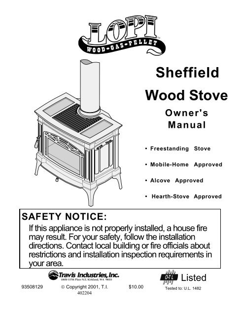
S h e f f i e l d<br />
<strong>Wood</strong> <strong>Stove</strong><br />
Owner's<br />
Manual<br />
• Freestanding <strong>Stove</strong><br />
• Mobile-Home Approved<br />
• Alcove Approved<br />
• Hearth-<strong>Stove</strong> Approved<br />
SAFETY NOTICE:<br />
If this appliance is not properly installed, a house fire<br />
may result. For your safety, follow the installation<br />
directions. Contact local building or fire officials about<br />
restrictions and installation inspection requirements in<br />
your area.<br />
10850 117th Place N.E. Kirkland, WA 98033<br />
93508129 © Copyright 2001, T.I. $10.00<br />
402204<br />
Listed<br />
Tested to: U.L. 1482
2 Introduction<br />
Introduction<br />
We welcome you as a new owner of a <strong>Lopi</strong> Sheffield wood-burning stove. In purchasing a <strong>Lopi</strong><br />
Sheffield you have joined the growing ranks of concerned individuals whose selection of an energy<br />
system reflects both a concern for the environment and aesthetics. The <strong>Lopi</strong> Sheffield is one of the<br />
finest appliances the world over. This manual will explain the installation, operation, and<br />
maintenance of this appliance. Please familiarize yourself with the Owner's Manual before operating<br />
your appliance and save the manual for future reference. Included are helpful hints and suggestions<br />
which will make the installation and operation of your new appliance an easier and more enjoyable<br />
experience. We offer our continual support and guidance to help you achieve the maximum benefit<br />
and enjoyment from your appliance.<br />
Important Information<br />
No other <strong>Lopi</strong> Sheffield appliance has the same serial<br />
number as yours. The serial number is stamped onto<br />
the label on the back of the appliance.<br />
This serial number will be needed in case you require<br />
service of any type.<br />
Model:<br />
Serial Number:<br />
Purchase Date:<br />
Purchased From:<br />
<strong>Lopi</strong> Sheffield<br />
Mail your Warranty Card Today,<br />
and Save Your Bill of Sale.<br />
To receive full warranty coverage, you will<br />
need to show evidence of the date you<br />
purchased your appliance. Do not mail<br />
your Bill of Sale to us.<br />
We suggest that you attach your Bill of Sale<br />
to this page so that you will have all the<br />
information you need in one place should<br />
the need for service or information occur.<br />
Travis Industries 93508129 4020204
Table of Contents 3<br />
General Information<br />
Introduction & Important Information ......................2<br />
Safety Precautions .............................................4<br />
Features & Specifications ....................................6<br />
<strong>Stove</strong> Installation<br />
Planning The Installation .....................................7<br />
Preparation for Installation ...................................7<br />
<strong>Stove</strong> Installation Considerations...........................7<br />
Leg Installation ..................................................8<br />
Floor Protection Requirements..............................8<br />
<strong>Stove</strong> Placement Requirements ............................9<br />
Clearances .......................................................9<br />
Chimney Requirements .......................................10<br />
Chimney Termination Requirements ......................11<br />
Outside Air Requirements ....................................11<br />
Alcove Installation Requirements...........................12<br />
Mobile Home Requirements .................................13<br />
INSTALLATION DIAGRAMS<br />
Standard Ceiling with a Factory Built Chimney.....13<br />
Cathedral Ceiling with a Factory Built Chimney....14<br />
Exterior Factory Built Chimney .........................14<br />
Hearth <strong>Stove</strong> Positive Connection.....................14<br />
Hearth <strong>Stove</strong> Direct Connection .......................15<br />
Interior Masonry Chimney ...............................15<br />
Operating Your Appliance<br />
Safety Notice ....................................................17<br />
Before Your First Fire..........................................17<br />
Opening the Door...............................................17<br />
Starting a Fire ...................................................18<br />
Adjusting the Burn Rate.......................................19<br />
Ash Removal ....................................................19<br />
Optional Blower Operation ...................................20<br />
Re-Loading the <strong>Stove</strong> .........................................20<br />
Overnight Burn ..................................................20<br />
Normal Operating Sounds....................................20<br />
Hints for Burning ................................................21<br />
Selecting <strong>Wood</strong> .................................................21<br />
Dry <strong>Wood</strong> is Key ...........................................21<br />
Testing <strong>Wood</strong> Moisture...................................21<br />
Why Dry <strong>Wood</strong> is Key.....................................21<br />
<strong>Wood</strong> Cutting and Storage ..............................21<br />
Troubleshooting.................................................22<br />
Maintaining Your Appliance<br />
Daily Maintenance..............................................23<br />
Remove Ash ................................................23<br />
Clean The Glass ...........................................23<br />
Monthly Maintenance..........................................24<br />
Door and Glass Inspection ..............................24<br />
Check For Creosote Buildup ............................24<br />
Yearly Maintenance............................................25<br />
Touch Up Paint .............................................25<br />
Blower Cleaning............................................25<br />
Firebrick and Baffle Inspection .........................25<br />
Door Parts ........................................................26<br />
Replacing the Glass.......................................26<br />
Replacing the Door Gasket..............................26<br />
Replacing the Door Handle..............................26<br />
Firebox Parts ....................................................27<br />
Floor & Side Firebrick Removal & Replacement...27<br />
Baffle Removal and Replacement .....................28<br />
Air Tube Removal and Replacement .................28<br />
Warranty<br />
Warranty ..........................................................29<br />
Listing Information<br />
Listing Information..............................................30<br />
Optional Equipment<br />
Outside Air Boot Installation .................................31<br />
Rear Blower Installation.......................................33<br />
Index<br />
Index ...............................................................36<br />
Travis Industries 93508129 4020204
4 Safety Precautions<br />
• The viewing door must be<br />
closed and latched during<br />
operation.<br />
• Never block free airflow<br />
through the air vents on this<br />
appliance.<br />
• This appliance is designed<br />
and approved for the<br />
burning of cord wood only.<br />
Do not attempt to burn any<br />
other type of fuel other than<br />
cord wood in this appliance,<br />
it will void all warranties and<br />
safety listings.<br />
• Do not touch the appliance<br />
while it is hot and educate<br />
all children of the danger of<br />
a high-temperature<br />
appliance. Young children<br />
should be supervised when<br />
they are in the same room<br />
as the appliance.<br />
• This appliance must be<br />
properly installed to prevent<br />
the possibility of a house<br />
fire. The instructions must<br />
be strictly adhered to. Do<br />
not use makeshift methods<br />
or compromise in the<br />
installation.<br />
• Inspect the chimney<br />
connector and chimney at<br />
least twice monthly and<br />
clean if necessary.<br />
Creosote may build up and<br />
cause a house fire.<br />
• Do not connect this<br />
appliance to any chimney<br />
serving another appliance.<br />
Travis Industries 93508129 4020204<br />
36"<br />
Gas<br />
ASHES<br />
Type<br />
HT<br />
Ok<br />
Clay<br />
Liner<br />
• Gasoline or other flammable<br />
liquids must never be used<br />
to start the fire or "Freshen<br />
Up" the fire. Do not store or<br />
use gasoline or other<br />
flammable liquids in the<br />
vicinity of this appliance.<br />
• Ashes must be disposed in<br />
a metal container with a<br />
tight lid and placed on a<br />
non-combustible surface<br />
well away from the home or<br />
structure.<br />
• Keep furniture, drapes,<br />
curtains, wood, paper, and<br />
other combustibles a<br />
minimum of 36" away from<br />
the front of the appliance.<br />
• Contact your local building<br />
officials to obtain a permit<br />
and information on any<br />
installation restrictions or<br />
inspection requirements in<br />
your area. Notify your<br />
insurance company of this<br />
appliance as well.<br />
• This appliance must be<br />
connected to a listed high<br />
temperature (UL 103 HT)<br />
residential type chimney or<br />
an approved masonry<br />
chimney with a standard<br />
clay tile, or stainless steel<br />
liner.
This<br />
Manual<br />
Mobile<br />
Home<br />
<br />
<br />
<br />
<br />
Safety Precautions 5<br />
• When installed in a mobile<br />
home, this appliance must<br />
be bolted to the floor, have<br />
outside air, and not be<br />
installed in the bedroom<br />
(Per H.U.D. requirements).<br />
Check with local building<br />
officials.<br />
• Never try to repair or replace<br />
any part of this appliance<br />
unless instructions are given<br />
in this manual. All other<br />
work must be done by a<br />
trained technician.<br />
• Allow the appliance to cool<br />
before carrying out any<br />
maintenance or cleaning.<br />
• Maintain the door and glass<br />
seal and keep them in good<br />
condition.<br />
• Avoid placing wood against<br />
the glass when loading. Do<br />
not slam the door or strike<br />
the glass.<br />
• Do not throw this manual<br />
away. This manual has<br />
important operating and<br />
maintenance instructions<br />
that you will need at a later<br />
time. Always follow the<br />
instructions in this manual.<br />
• Do not place clothing or<br />
other flammable items on or<br />
near this appliance.<br />
• Do not make any changes<br />
or modifications to an<br />
existing masonry fireplace<br />
or chimney to install this<br />
appliance.<br />
• Do not make any changes to<br />
the appliance to increase<br />
combustion air.<br />
• Overfiring the appliance may<br />
cause a house fire. If a unit<br />
or chimney connector glows,<br />
you are overfiring.<br />
• Do not use a grate or other<br />
device to elevate the fire off<br />
of the firebox floor. Burn the<br />
fire directly on the bricks.<br />
• Travis Industries, Inc.<br />
grants no warranty,<br />
implied or stated, for<br />
the installation or<br />
maintenance of your<br />
appliance, and<br />
assumes no<br />
responsibility of any<br />
consequential<br />
damage(s).<br />
Travis Industries 93508129 4020204
6 Features & Specifications<br />
Installation Options:<br />
• Freestanding<br />
• Freestanding in an Alcove<br />
• Freestanding in a Mobile Home<br />
Heating Specifications:<br />
Features:<br />
• EPA Phase II Approved<br />
• 1.3 Cubic Foot Firebox Volume<br />
• Single Operating Control<br />
• Accepts Logs Up to 17" Long<br />
• Cast Iron & Steel Plate (1/4" & 3/16")<br />
• Heavy Duty Refractory Firebrick<br />
• Optional High-Tech Blower<br />
Approximate Maximum Heating Capacity (in square feet)* 600 to 1,200<br />
Maximum BTU's per Hour (Cord <strong>Wood</strong> Calculation) 64,300<br />
Overall Efficiency (Oregon Method) 70.0 %<br />
Maximum Burn Time Up to 8 Hours<br />
* Heating capacity will vary depending on the home's floor plan, degree of insulation, and the outside<br />
temperature. It is also affected by the quality and moisture level of the fuel.<br />
Dimensions:<br />
Emissions:<br />
3.9 Grams Per<br />
Hour (EPA Phase<br />
II Approved) –<br />
Tests conducted<br />
by Myren<br />
Consulting Inc.<br />
19-1/4" 5-1/2"<br />
15-7/8"<br />
26-3/4"<br />
29-1/2"<br />
The flue collar<br />
protrudes 1-1/4"<br />
above the stove top<br />
NOTE:<br />
Measure side, corner,<br />
and back clearances<br />
from the stove top.<br />
Travis Industries 93508129 4020204
Installation (for qualified installers only) 7<br />
SAFETY NOTICE:<br />
Please read this entire manual before you install and use your new<br />
room heater. Failure to follow instructions may result in property<br />
damage, bodily injury, or even death. Contact local building or fire<br />
officials about restrictions and installation inspection requirements<br />
in your area.<br />
Planning The Installation<br />
We suggest that you have an authorized Travis Industries dealer install your stove. If you install the<br />
stove yourself, your authorized dealer should review your plans for installation.<br />
Check with local building officials for any permits required for installation of this stove and notify your<br />
insurance company before proceeding with installation.<br />
Preparation for Installation<br />
• Check for damage to the exterior of the stove (dents should be reported, scratches can be fixed by<br />
applying touch up paint).<br />
• Check the interior of the firebox (replace cracked firebrick and make sure baffle is in place).<br />
The stove can be lightened by removing the firebricks and baffle. (pg 26) - replace before operation.<br />
<strong>Stove</strong> Installation Considerations<br />
The table below details the six most common types of installations and the considerations for each<br />
type. Alternative methods of installation are available if they comply with local building codes.<br />
Installation Type Considerations<br />
Standard Ceiling with a Factory Built Chimney<br />
(Page 14)<br />
Cathedral Ceiling with a Factory Built Chimney<br />
(Page 14)<br />
Exterior Factory Built Chimney<br />
(Page 15)<br />
Hearth <strong>Stove</strong> Positive Connection<br />
(Page 15)<br />
Hearth <strong>Stove</strong> Direct Connection<br />
(Page 16)<br />
Hearth <strong>Stove</strong> Horizontal Connection<br />
(Page 16)<br />
• Requires ceiling and roof penetration<br />
• Provides best draft<br />
• Cathedral style chimney support required<br />
• Provides best draft<br />
• Uses two elbows to route chimney outside<br />
• Exterior chimney is hidden from the room<br />
• Elbows reduce draft<br />
• Optional exterior chase reduces cold air blockage<br />
• Utilizes existing masonry or zero clearance (metal) chimney<br />
• Provides good draft due to full reline<br />
• Easier to clean than direct or horizontal hearth stove<br />
• Utilizes existing masonry or zero clearance (metal) chimney<br />
• Requires construction of a "block-off plate"<br />
• Draft reduced due to elbows & chimney cross section<br />
• Utilizes existing masonry chimney (not approved for zero<br />
clearance (metal) fireplaces)<br />
• Draft is good because of vertical section above stove<br />
Travis Industries 93508129 4020204
8 Installation (for qualified installers only)<br />
Floor Protection Requirements<br />
• <strong>Stove</strong> must be placed on the included legs.<br />
Floor protection must be<br />
non-combustible and at least<br />
.018" thick (26 gauge).<br />
<br />
<br />
Min. 6”<br />
Min. 6”<br />
<br />
<br />
Min. 6”<br />
<br />
Min. 16”<br />
<br />
Minimum<br />
Minimum 37-7/8”<br />
<br />
38-3/4”<br />
<br />
NOTE : In corner installations with reduced-clearance connector, the clearance to the wall is less<br />
than 6". In this case, floor protection must extend to the wall.<br />
Leveling Bolts<br />
Make sure these rubber tipped<br />
bolts on each leg contact the floor<br />
(they dampen any noise that may<br />
transmit through the hearth). Do<br />
not adjust with weight on the legs,<br />
the rubber tips may tear.<br />
Travis Industries 93508129 4040915
Installation (for qualified installers only) 9<br />
<strong>Stove</strong> Placement Requirements<br />
Clearances may be reduced by methods specified in NFPA 211, listed wall shields, pipe shields, or<br />
other means approved by local building or fire officials.<br />
• <strong>Stove</strong> must be placed so that no combustibles are within, or can swing within (e.g. drapes, doors),<br />
36" of the front of the stove<br />
• If the stove is placed in a location where the ceiling height is less than 7', it must follow the<br />
requirements in the section "Alcove Installation Requirements"<br />
• Must maintain the clearances to combustibles listed below (drywall, furniture, etc.):<br />
Clearances<br />
a<br />
d<br />
Straight Installations<br />
e<br />
b<br />
Corner Installations<br />
NOTE:<br />
Measure stove clearances to the stove top.<br />
Minimum Clearance<br />
Singlewall Reduced<br />
(See the illustration above) Connector Clearance*<br />
A Sidewall to stove 10" 10"<br />
B Backwall to stove 16-1/2" 10-1/2"<br />
C Cornerwall to stove 7-3/4" 3"<br />
D Connector to sidewall 20-1/2" 20"<br />
E Connector to backwall 15-1/2" 9"<br />
F Connector to cornerwall 15-1/2" 10-1/4"<br />
*Reduced clearance installations require one of the chimneys and connectors listed below:<br />
• DURAVENT model DVL with DURATEC chimney<br />
• DURAVENT model DVL with DURA-PLUS chimney<br />
• AMERI-TEC model DCC with model HS chimney<br />
• SECURITY model DL with SECURITY model ASHT or S2100 chimney<br />
• METAL-FAB model DW with TG chimney<br />
• GSW Double Wall Chimney Connector with Super Chimney Twenty-One<br />
• SELKIRK METALBESTOS model DS connector with model SSII chimney<br />
• I.C.C. Excel (2100-2 Can.) (103-HT USA) chimney with HP connector<br />
• Standard Masonry Chimney with any one of the above listed connectors<br />
NOTE: Standard residential installations with reduced clearance connector may use the clearance<br />
determined by the manufacturer of the connector for the connector to wall clearance or the<br />
clearance listed in this manual. Offsets must be used to maintain the stove to wall clearance.<br />
NOTE: Reduced clearance connectors may not connect to the flue collar – order an appliance<br />
adapter for the connector being used.<br />
Travis Industries 93508129 4020204<br />
f<br />
c
10 Installation (for qualified installers only)<br />
Chimney Requirements<br />
• Chimney connector must be a minimum 24 MSG black or 26 MSG blued steel (6" diameter).<br />
Chimney must be used from the first floor or wall penetration to the chimney cap.<br />
• Use 6" diameter type UL 103 HT chimney from one manufacturer (do not mix brands) or code<br />
approved masonry chimney with a flue liner.<br />
• Chimney connector and chimney must be fastened to the stove and each adjoining section.<br />
• Follow the chimney manufacturer's clearances and requirements.<br />
• Do not connect this unit to a chimney flue serving another appliance.<br />
• Use the chimney manufacturer's fire stops, attic guards, roof supports, and flashings when<br />
passing through a ceiling or thimble when passing through a combustible wall.<br />
• No more than 180 o of elbows (two 90 o elbows, or two 45 o & one 90 o elbow, etc.).<br />
NOTE: Additional elbows may be allowed if draft is sufficient. Whenever elbows are used the draft is<br />
adversely affected. Additional chimney height may be required to boost draft.<br />
Drafting<br />
Performance<br />
Chimney Cap<br />
(See the section<br />
"Chimney Termination<br />
Requirements" for<br />
more details)<br />
Factory Built<br />
Chimney<br />
Sections<br />
Floor Penetration<br />
Equipment (Attic<br />
Radiation Shield with<br />
Chimney Support)<br />
Reduced<br />
Clearance<br />
Chimney<br />
Connector<br />
Sections<br />
Floor<br />
Protection<br />
<br />
<br />
<br />
<br />
<br />
<br />
<br />
<br />
<br />
<br />
<br />
<br />
}<br />
<br />
}<br />
} Roof Penetration Equipment<br />
(Roof Radiation Shield,<br />
Flashing, Storm Collar)<br />
Minimum Air Space to<br />
Combustibles (See<br />
Chimney Manufacturer's<br />
Instructions - usually 2")<br />
Standard residential installations with<br />
reduced clearance connector may use the<br />
clearance determined by the manufacturer<br />
of the connector for the connector to wall<br />
clearance or the clearance listed in this<br />
manual.<br />
Mobile home installations<br />
Connector must maintain 9” clearance to<br />
the wall with any offset a minimum 12”<br />
from the ceiling.<br />
<strong>Stove</strong> Clearance<br />
(as outlined in this manual)<br />
Minimum System 15'<br />
Maximum System 33'<br />
This appliance relies upon natural draft to operate. External forces, such as wind,<br />
barometric pressure, topography, or factors of the home (negative pressure from exhaust<br />
fans, chimneys, air infiltration, etc.), may adversely affect draft. Travis Industries can not be<br />
responsible for external forces leading to less than optimal performance.<br />
• Standard residential installations may use single-wall connector (Mobile-Homes may not )<br />
• Standard residential installations with reduced clearance connector may use the clearance<br />
determined by the manufacturer of the connector for the connector to wall clearance or the clearance<br />
listed in this manual. Offsets must be used to maintain the stove to wall clearance. Mobile homes<br />
must use the clearances listed in this manual under "Additional Requirements for Mobile Home<br />
Installations".<br />
Travis Industries 93508129 4020204
Installation (for qualified installers only) 11<br />
Chimney Termination Requirements<br />
• Must have an approved cap (to prevent water from entering)<br />
• Must not be located where it will become plugged by snow or other material<br />
• Must terminate at least 3' above the roof and at least 2' above any portion of the roof within 10'<br />
Slanted Roofs<br />
Flat Roofs<br />
Chimney must<br />
extend 3'<br />
above the roof<br />
Chimney must<br />
extend 3'<br />
above the roof<br />
Outside Air Requirements<br />
Chimney must extend 2'<br />
above any portion of the roof<br />
within 10' of the chimney<br />
• Required for mobile homes & in certain localities (check with building officials)<br />
• Must not be drawn from an enclosed space (garage, unventilated crawl space)<br />
• Requires the optional outside air boot (see page 31).<br />
HINT:<br />
When using outside air, find a location where the chimney and<br />
outside air hole do not interfere with structural members of the home.<br />
A hole must be cut through the floor protection and<br />
floor and the rodent screen nailed in place here (see<br />
the optional equipment instructions for exact sizes)<br />
NOTE:<br />
Air may be drawn from a ventilated<br />
crawl space or through an air duct.<br />
<br />
<br />
<br />
<br />
<br />
<br />
Maximum duct length is 15’ with a cross section of 16 square inches (e.g. 8” by 2”<br />
duct). If under 5’ long, the cross section may be a minimum 12 square inches.<br />
Chimney must extend 2'<br />
above any portion of the roof<br />
within 10' of the chimney<br />
<br />
<br />
<br />
Outside<br />
Air Boot<br />
Outside air entrance<br />
must be placed so it<br />
does not become<br />
blocked by snow.<br />
Travis Industries 93508129 4020204
12 Installation (for qualified installers only)<br />
Alcove Installation Requirements<br />
Whenever the stove is placed in a location where the ceiling height is less than 7' tall, it is considered<br />
an alcove installation. Because of the reduced height, the special installation requirements listed<br />
below must be met.<br />
• Chimney connector and chimney must be one of the following types:<br />
• DURAVENT model DVL with DURATEC chimney<br />
• DURAVENT model DVL with DURA-PLUS chimney<br />
• AMERI-TEC model DCC with model HS chimney<br />
• SECURITY model DL with SECURITY model ASHT or S2100 chimney<br />
• METAL-FAB model DW with TG chimney<br />
• GSW Double Wall Chimney Connector with Super Chimney Twenty-One<br />
• SELKIRK METALBESTOS model DS connector with model SSII chimney<br />
• I.C.C. Excel (2100-2 Can.) (103-HT USA) chimney with HP connector<br />
• Standard Masonry Chimney with any one of the above listed connectors<br />
Minimum Clearance<br />
(See the illustration above)<br />
Combustible<br />
Alcove<br />
Non-Combustible<br />
Alcove<br />
A Sidewall to stove 10" 6"<br />
B Backwall to stove 10-1/2" 2"<br />
D Connector to sidewall 20" 16-1/2"<br />
E Connector to backwall 9" 1"<br />
G Maximum Depth of Alcove 48" 48"<br />
H Minimum Width of Alcove 46-3/4" 38-3/4"<br />
J Minimum Height of Alcove 84" 6" Above <strong>Stove</strong> Top<br />
• Alcoves are classified as combustible or non-combustible. Non-combustible alcoves must have<br />
walls and a ceiling that are 3 1/2" thick of a non-combustible material (brick, stone, or concrete).<br />
This non-combustible material must be spaced and ventilated at least 1" off of all combustible<br />
materials (walls, ceiling, etc.) to allow air to move around the non-combustible walls and ceiling.<br />
All other alcoves are considered combustible. The clearances below must be met:<br />
Non-combustible alcove<br />
construction (on walls<br />
and ceiling) - see the<br />
explanation above.<br />
Ventilated<br />
air space<br />
1" Min.<br />
Combustible<br />
materials<br />
<br />
<br />
<br />
<br />
3 1/2" thick noncombustible<br />
material<br />
Non-combustible<br />
reinforcer<br />
j<br />
Travis Industries 93508129 4020204<br />
h<br />
a<br />
d<br />
e<br />
g<br />
b
Installation (for qualified installers only) 13<br />
Mobile Home Requirements<br />
• Outside air must be installed - see "Outside Air Requirements" on page 11<br />
• Chimney connector and chimney must be one of the following types:<br />
• DURAVENT model DVL with DURATEC chimney<br />
• DURAVENT model DVL with DURA-PLUS chimney<br />
• AMERI-TEC model DCC with model HS chimney<br />
• SECURITY model DL with SECURITY model ASHT or S2100 chimney<br />
• METAL-FAB model DW with TG chimney<br />
• GSW Double Wall Chimney Connector with Super Chimney Twenty-One<br />
• SELKIRK METALBESTOS model DS connector with model SSII chimney<br />
• I.C.C. Excel (2100-2 Can.) (103-HT USA) chimney with HP connector<br />
• Standard Masonry Chimney with any one of the above listed connectors<br />
NOTE: Reduced clearance connectors may not connect to the flue collar – order an appliance<br />
adapter for the connector being used.<br />
• <strong>Stove</strong> placement must maintain the following clearances to combustibles (drywall, furniture, etc.)<br />
Minimum Clearance<br />
Reduced Clearance<br />
(See the illustration below) Connector<br />
A Sidewall to stove 10"<br />
B Backwall to stove 10-1/2"<br />
C Cornerwall to stove 3"<br />
D Connector to sidewall 20"<br />
E Connector to backwall 9"<br />
F Connector to cornerwall 10-1/4"<br />
a<br />
d<br />
Straight Installations<br />
e<br />
b<br />
Corner Installations<br />
NOTE:<br />
Measure stove clearances to the stove top.<br />
• If using offsets, use the connector clearance listed to the<br />
right, not the connector manufacturer's<br />
clearance.<br />
• The appliance must be secured to the floor (consult your<br />
building official). Secure the outside air boot to the floor<br />
and stove to insure the stove does not dislocate.<br />
• Mobile home installations require a spark arrester at the<br />
chimney termination.<br />
• The appliance must be grounded to the chassis of the<br />
mobile home (consult your building official).<br />
WARNING: DO NOT INSTALL IN SLEEPING ROOM.<br />
CAUTION: THE STRUCTURAL INTEGRITY OF THE<br />
MOBILE HOME FLOOR, WALL, AND<br />
CEILING/ROOF MUST BE MAINTAINED.<br />
Travis Industries 93508129 4020204<br />
f<br />
c<br />
12” Min.<br />
Connector Clearance<br />
(as outlined above)<br />
<strong>Stove</strong> Clearance<br />
(as outlined above)
14 Installation (for qualified installers only)<br />
Standard<br />
Ceiling with<br />
a Factory<br />
Built<br />
Chimney<br />
Cathedral<br />
Ceiling with<br />
a Factory<br />
Built<br />
Chimney<br />
Chimney Cap<br />
(See the section "Chimney<br />
Termination Requirements"<br />
for more details)<br />
Chimney Sections<br />
Insulation<br />
Follow the chimney<br />
manufacturer's instructions<br />
and clearances for floor<br />
penetrations. A ceiling<br />
support is required, an attic<br />
insulation shield is required<br />
where insulation is present.<br />
Chimney Connector Sections<br />
Floor Protection<br />
(See the section "Floor<br />
Protection Requirements"<br />
for more details)<br />
Chimney Cap<br />
(See the section "Chimney<br />
Termination Requirements"<br />
for more details)<br />
Chimney Sections<br />
Minimum Air Space to<br />
Combustibles (See Chimney<br />
Manufacturer's Instructions -<br />
usually 2")<br />
Floor Protection<br />
(See the section "Floor<br />
Protection Requirements"<br />
for more details)<br />
<br />
<br />
<br />
<br />
<br />
<br />
}<br />
<br />
<br />
<br />
Chimney<br />
Connector<br />
Sections<br />
<br />
<br />
<br />
Follow the chimney<br />
manufacturer's instructions<br />
and clearances for roof<br />
penetrations. A storm collar<br />
and flashing are required<br />
(some require a radiation<br />
shield).<br />
Minimum Air Space to<br />
Combustibles (See<br />
Chimney Manufacturer's<br />
Instructions - usually 2")<br />
Travis Industries 93508129 4020204<br />
}<br />
<br />
<br />
<br />
<br />
<br />
<br />
}<br />
Minimum 15'<br />
Maximum 33'<br />
<strong>Stove</strong> Clearances<br />
(See the section "<strong>Stove</strong><br />
Placement Requirements"<br />
for more details)<br />
Follow the chimney<br />
manufacturer's instructions<br />
and clearances for roof<br />
penetrations. A storm<br />
collar, flashing, and<br />
cathedral-style chimney<br />
support are required<br />
(some require a radiation<br />
shield).<br />
Minimum 15'<br />
Maximum 33'<br />
<strong>Stove</strong> Clearances<br />
(See the section "<strong>Stove</strong><br />
Placement Requirements"<br />
for more details)
Exterior<br />
Factory<br />
Built<br />
Chimney<br />
NOTE:<br />
Exterior chimneys<br />
are subject to<br />
greater moisture<br />
and creosote<br />
accumulation due<br />
to the lower<br />
temperatures. An<br />
insulated chase<br />
will reduce these<br />
accumulations<br />
(the proper<br />
clearances to the<br />
chimney must be<br />
maintained).<br />
Hearth<br />
<strong>Stove</strong><br />
Positive<br />
Connection<br />
NOTE:<br />
Most factory-built<br />
chimney<br />
manufacturers<br />
make stainless<br />
steel chimney<br />
liners, either<br />
flexible or rigid.<br />
This provides a<br />
wide variety of<br />
installation<br />
options. Make<br />
sure to follow the<br />
manufacturer's<br />
instructions for<br />
installation and<br />
support.<br />
Installation (for qualified installers only) 15<br />
Chimney Cap<br />
(See the section "Chimney<br />
Termination Requirements"<br />
for more details)<br />
Chimney Sections<br />
Minimum Air Space to<br />
Combustibles (See<br />
Chimney Manufacturer's<br />
Instructions - usually 2")<br />
Min. 18"<br />
clearance to<br />
ceiling<br />
Chimney Connector<br />
Sections<br />
Floor Protection<br />
(See "Floor<br />
Protection<br />
Requirements"<br />
for details)<br />
Wall Bands<br />
and<br />
Supports<br />
<br />
NOTE: The entire fireplace and<br />
chimney must be clean, undamaged,<br />
and meet all local building codes<br />
(UBC, etc.). Damage must be<br />
repaired prior to installation. The<br />
chimney must be 15' to 33' tall.<br />
Combustible<br />
Mantle<br />
Floor Protection<br />
(See the section<br />
"Floor Protection<br />
Requirements"<br />
for more details)<br />
Min. 18"<br />
<br />
} <br />
<br />
<br />
<br />
<br />
<br />
<br />
<br />
<br />
<br />
<br />
<br />
<br />
<br />
Follow the chimney<br />
manufacturer's<br />
instructions and<br />
clearances for roof<br />
penetrations. A storm<br />
collar and flashing are<br />
required (some<br />
require a radiation<br />
shield).<br />
Follow the chimney<br />
manufacturer's<br />
instructions and<br />
clearances for wall<br />
penetrations. A<br />
wall radiation shield<br />
(thimble) is<br />
required.<br />
<strong>Stove</strong> Clearances<br />
(See the section "<strong>Stove</strong> Optional<br />
Placement Requirements" insulated<br />
for more details)<br />
chase<br />
Travis Industries 93508129 4020204<br />
}<br />
<br />
<br />
<br />
<br />
<br />
<br />
<br />
Minimum 15'<br />
Maximum 33'<br />
<br />
<br />
<br />
<br />
Insulated Tee<br />
(with cleanout )<br />
Cap and flashing<br />
prevents water from<br />
entering<br />
The liner must be<br />
stainless steel connector<br />
or flexible vent. Follow<br />
the liner manufacturer's<br />
instructions for installation<br />
and support.<br />
Airtight Insulated<br />
Clean-Out<br />
Remove damper<br />
or wire it open<br />
See the section<br />
"<strong>Stove</strong> Placement<br />
Requirements" for<br />
minimum clearances<br />
required.
16 Installation (for qualified installers only)<br />
Hearth<br />
<strong>Stove</strong><br />
Direct<br />
Connection<br />
NOTE:<br />
Direct<br />
connections<br />
require installation<br />
of an airtight, noncombustible<br />
block-off plate or<br />
damper adapter.<br />
Interior or<br />
Exterior<br />
Masonry<br />
Chimney<br />
NOTE:<br />
This type of<br />
installation<br />
requires a UBC<br />
approved<br />
masonry<br />
connector or a<br />
factory built (U.L.<br />
Listed) wall<br />
thimble.<br />
NOTE: The chimney must have a clay<br />
tile liner. If it does not, the installation<br />
must use a positive connection (full<br />
reline). The entire fireplace and<br />
chimney must be clean, undamaged,<br />
and meet all local building codes (UBC,<br />
etc.). Damage must be repaired prior<br />
to installation. The chimney must be<br />
15' to 33' tall.<br />
Combustible<br />
Mantle<br />
Floor Protection<br />
(See the section "Floor<br />
Protection Requirements"<br />
for more details)<br />
NOTE: The chimney must have a<br />
clay tile liner. If it does not, the<br />
installation must use a positive<br />
connection (full reline). The<br />
entire fireplace and chimney must<br />
be clean, undamaged, and meet<br />
all local building codes (UBC,<br />
etc.). Damage must be repaired<br />
prior to installation. The chimney<br />
must be 15' to 33' tall.<br />
See the section "<strong>Stove</strong><br />
Placement Requirements" for<br />
minimum clearances required.<br />
Chimney connector sections<br />
See the section<br />
"Floor Protection<br />
Requirements"<br />
Min. 18"<br />
Min. 18"<br />
clearance<br />
to ceiling<br />
<br />
<br />
<br />
<br />
<br />
<br />
<br />
<br />
<br />
Clay<br />
Liner<br />
Stainless steel<br />
chimney connector<br />
must Extend 1' past<br />
the block-off plate or<br />
to the flue liner<br />
Airtight<br />
Insulated<br />
Clean-Out<br />
Remove damper<br />
or wire it open<br />
Block-off plate or<br />
damper adapter<br />
See the section<br />
"<strong>Stove</strong> Placement<br />
Requirements" for<br />
minimum clearances<br />
required.<br />
Clay Liner<br />
This type of<br />
installation requires<br />
a UBC approved<br />
masonry connector<br />
or a factory built<br />
(U.L. Listed) wall<br />
thimble.<br />
Make sure the<br />
clean-out seals in<br />
place.<br />
Travis Industries 93508129 4020204
Safety Notice:<br />
Operating Your Appliance 17<br />
If this appliance is not properly installed, a house fire may result. For your safety, follow the installation<br />
directions. Contact local building or fire officials about restrictions and installation inspection<br />
requirements in your area.<br />
Read and follow all of the warnings on pages 4 and 5 of this manual.<br />
Before Your First Fire<br />
Verify the Installation<br />
Before starting the stove, verify that the stove is properly installed and all of the requirements in this<br />
manual have been followed.<br />
Keep all flammable materials 36" away from the front of the stove (drapes, furniture, clothing, etc.).<br />
Curing the Paint<br />
This heater uses a heat-activated paint that<br />
will emit some fumes while starting the first<br />
fire. Open doors and windows to the room to<br />
vent these fumes. This typically lasts two to<br />
four hours. You may also notice oil burning off<br />
of the interior of the heater. This rust-stopping<br />
agent will soon dissipate.<br />
Over-Firing the <strong>Stove</strong><br />
2 to 4 hours<br />
<br />
<br />
<br />
<br />
This stove was designed to operate at a high temperature. But due to differences in vent<br />
configuration, fuel, and draft, this appliance can be operated at an excessive temperature. If the<br />
stove top or other area starts to glow red, you are over-firing the stove. Shut the air control down to<br />
low and allow the stove to cool before proceeding.<br />
Opening the Door<br />
Lift the<br />
door<br />
handle.<br />
Swing<br />
the door<br />
open.<br />
The door becomes hot during use. Use a glove to open the door if the handle is hot.<br />
To prevent smoke from entering the room, open the door a small amount and let air enter the firebox.<br />
This stabilizes the air flow before opening the door completely.<br />
Travis Industries 93508129 4020204
18 Operating Your Appliance<br />
Starting a Fire<br />
Since the dawn of time man has debated the best way to start a fire. Some use the boy-scout "teepee",<br />
some prefer the "tic-tac-toe" stack. Either way, review the hints and warnings below to ensure<br />
proper fire starting.<br />
• Make sure the air control is pushed in. If additional air is needed, open the doors 1/4" during the first<br />
five minutes of start-up.<br />
Never use gasoline, gasoline-type lantern fuel, kerosene, charcoal lighter fluid, or similar liquids to start<br />
or "freshen up" a fire in this stove. Keep all such liquids well away from the stove while it is in use.<br />
If using a firestarter, use only products specifically designed for stoves - follow the manufacturer's<br />
instructions carefully.<br />
If the smoke does not pass up the chimney, ball up one sheet of newspaper, place it in the center of the<br />
grate and light it. This should start the chimney drafting (this eliminates "cold air blockage").<br />
Use plenty of kindling to ensure the stove reaches a proper temperature. Once the kindling is burning<br />
rapidly, place a few larger pieces of wood onto the fire.<br />
Travis Industries 93508129 4020204
Operating Your Appliance 19<br />
Adjusting the Burn Rate<br />
Use the air control slider to control the burn rate of the stove. See the illustration below for details.<br />
Use the air control to<br />
change the burn rate.<br />
Low Burn<br />
(air control closed)<br />
<br />
<br />
<br />
<br />
High Burn<br />
(air control open)<br />
<br />
Approximate Air Control<br />
Settings:<br />
Overnight Burn .............. Fully closed to 3/8" open<br />
Medium Burn.................. 3/8" open to 7/16" open<br />
Medium High Burn ........ 7/16" open to 1/2" open<br />
High Burn........................ 1/2" to fully open<br />
The air control becomes hot during operation - use gloves or a tool to prevent burns.<br />
The air control may take several minutes to influence the burn rate. When making adjustments, you may<br />
wish to let the stove burn for 10 minutes to gauge performance.<br />
Ash Removal<br />
ASHES<br />
Ashes should be placed in a metal container with a tight fitting lid. The closed container of ashes<br />
should be placed on a noncombustible floor or on the ground, away from all combustible<br />
materials, pending final disposal. If the ashes are disposed of by burial in soil or otherwise locally<br />
dispersed, they should be retained in the closed container until all cinders have thoroughly<br />
cooled.<br />
Travis Industries 93508129 4020204
20 Operating Your Appliance<br />
Optional Blower Operation<br />
The blower will turn on once the stove is up to temperature. This is typically 15 to 30 minutes after<br />
starting the fire. Follow the directions below to alter the blower speed.<br />
OFF<br />
Turn the dial all the way counterclockwise<br />
until it clicks off.<br />
OFF<br />
HI<br />
<br />
LO<br />
<br />
<br />
<br />
BLOWER<br />
CONTROL<br />
HIGH<br />
The high position is all the way counterclockwise,<br />
without clicking off.<br />
OFF<br />
HI<br />
<br />
LO<br />
<br />
<br />
<br />
BLOWER<br />
CONTROL<br />
Travis Industries 93508129 4020204<br />
LOW<br />
Turn the dial all the<br />
way clockwise.<br />
OFF<br />
HI<br />
<br />
LO<br />
<br />
<br />
<br />
BLOWER<br />
CONTROL<br />
The blower may be used to affect heat output (i.e.: to reduce heat output, turn the blower down).<br />
Route the power cord in a location where it will not come in contact with the appliance or become hot.<br />
Re-Loading the <strong>Stove</strong><br />
Follow the directions below to minimize smoke spillage while re-loading the stove.<br />
1 Push the air control all the way in (high burn).<br />
2 Open the door slightly. Let the airflow inside the firebox to stabilize before opening the doors fully.<br />
3 Load wood onto the fire.<br />
Overnight Burn<br />
This stove is large enough to accommodate burn times up to eight hours. Follow the steps below to<br />
achieve an overnight burn.<br />
1 Move the air control to high burn and let the stove become hot (burn for approximately 15 minutes).<br />
2 Load as much wood as possible. Use large pieces if possible.<br />
3 Let the stove burn on high for 15 minutes to keep the stove hot, then turn the air control to low.<br />
4 In the morning the stove should still be hot, with embers in the coal bed. Stir the coals and load small<br />
pieces of wood to re-ignite the fire, if desired.<br />
Differences if chimney height and draft may lower overall burn times.<br />
Normal Operating Sounds<br />
Creaks and Clicks:<br />
The 3/16" and 5/16" steel may creak or click<br />
when the stove heats up and cools down - this<br />
is normal.<br />
Blower Sounds:<br />
The blower will make a slight "humm" as it<br />
pushes air through the stove.
Operating Your Appliance 21<br />
Hints for Burning<br />
• Get the appliance hot before adjusting to low burn<br />
• Use smaller pieces of wood during start-up and high burns to increase temperature<br />
• Use larger pieces of wood for overnight or sustained burns<br />
• Stack the wood tightly together to establish a longer burn<br />
• Leave a bed of ashes (1/2" deep) to allow for longer burns<br />
• Be considerate of neighbors & the environment: burn dry wood only<br />
• Burn small, intense fires instead of large, slow burning fires when possible<br />
• Learn your appliance's operating characteristics to obtain optimum performance<br />
Selecting <strong>Wood</strong><br />
Dry <strong>Wood</strong> is Key<br />
Dry wood burns hot, emits<br />
less smoke and creates<br />
less creosote.<br />
Testing <strong>Wood</strong><br />
Moisture<br />
Split wood stored in a dry<br />
area will be fully dry within<br />
a year. This insures dry<br />
wood. If purchasing wood<br />
for immediate use, test the<br />
wood with a moisture<br />
meter. Some experienced<br />
wood burners can measure<br />
wood moisture by knocking<br />
pieces together and<br />
listening for a clear "knock"<br />
and not a "thud".<br />
Why Dry <strong>Wood</strong> is Key<br />
Wet<br />
<strong>Wood</strong><br />
Less<br />
Heat<br />
Leads<br />
To<br />
Leads<br />
To<br />
More Smoke<br />
and Creostoe<br />
Dry<br />
<strong>Wood</strong><br />
More<br />
Heat<br />
Leads<br />
To<br />
Leads<br />
To<br />
Less Smoke<br />
and Creostoe<br />
Wet wood, when burned, must release water stored within the wood. This cools the fire, creates<br />
creosote, and hampers a complete burn. Ask any experienced wood burner and he or she will agree:<br />
dry wood is crucial to good performance.<br />
<strong>Wood</strong> Cutting and Storage<br />
Cut wood to length and<br />
chop into quarters.<br />
Store the wood off the ground in a<br />
covered area. Allow for airflow<br />
around the wood to dry the wood.<br />
Air Flow<br />
Air Flow<br />
Air Flow<br />
Travis Industries 93508129 4020204
22 Operating Your Appliance<br />
Troubleshooting<br />
Problem Possible Cause<br />
Smoke Enters Room<br />
During Start-Up<br />
Kindling Does Not Start -<br />
Fire Smolders<br />
Smoke Enters Room<br />
While Re-Loading<br />
<strong>Stove</strong> Does Not Burn Hot<br />
Enough<br />
• Cold Air Blockage - burn a piece of newspaper to<br />
establish a draft.<br />
• Close the doors - if the flame is not getting enough air,<br />
first make sure the air control is open (all the way in).<br />
If additional air is needed, a small crack in the door is<br />
all that is needed.<br />
• Cold Air Blockage - burn a piece of newspaper to<br />
establish a draft.<br />
• Not enough starter paper - use additional newspaper if<br />
necessary.<br />
• Not enough air - first make sure the air control is open<br />
(all the way in). If additional air is needed, a small<br />
crack in the door is all that is needed.<br />
• Let the air stabilize before fully opening the door. Push<br />
the air control in before opening the door. Then open<br />
the door approximately 1 inch. Let air go into the<br />
firebox for a few seconds. Once the smoke appears to<br />
be flowing up the chimney consistently, open the door.<br />
• Insufficient Draft - Chimney height and outside<br />
conditions can negatively affect draft. In these cases a<br />
small amount of smoke may enter the home. Adding<br />
more pipe or a draft-inducing cap may help.<br />
• <strong>Wood</strong> is Wet - see the section "Selecting <strong>Wood</strong>" on<br />
page 21 for details on wood.<br />
• Insufficient Draft - Chimney height and outside<br />
conditions can negatively affect draft. In these cases<br />
the fire may burn slowly. Adding more pipe or a draftinducing<br />
cap may help.<br />
• Air Control is Not Wide Open - Make sure the air<br />
control is all the way in. Slide the control back and<br />
forth to insure the control is not stuck.<br />
Blower Does Not Run • <strong>Stove</strong> is Not Up to Temperature - This is normal. The<br />
blower will come on when the stove is hot - usually 15<br />
to 30 minutes.<br />
• Electricity is Cut to the Blower - Check the household<br />
breaker or fuse to make sure it is operable.<br />
<strong>Stove</strong> Does Not Burn<br />
Long Enough<br />
• This appliance burns for up to 8 hours. Depending<br />
upon wood, draft, and other factors, the burn time may<br />
be shorter. Make sure the doors are sealing and not<br />
allowing air into the firebox - See the section "Door and<br />
Glass Inspection" on page 24 for details.<br />
• Check the ash bed for coals. Often, coals are still<br />
glowing under a slight bed of flyash. By raking these<br />
into a pile you can re-start your stove quickly.<br />
Travis Industries 93508129 4020204
Maintaining Your Appliance 23<br />
Failure to properly maintain and inspect your appliance may reduce the performance and life of the<br />
appliance, void your warranty, and create a fire hazard.<br />
Daily Maintenance (while stove is in use)<br />
Remove Ash (if necessary)<br />
1<br />
Ash removal is not required once it builds up. 1/2" to 1" of ash may be desirable because it slows the<br />
burn rate. Generally, remove ash once it has built up over 1". Follow the directions below to remove<br />
ash.<br />
Let the stove cool completely (at least two hours after the last coal has extinguished).<br />
2 Place a cloth or cardboard protector over the hearth to catch ash and protect against<br />
scratching.<br />
3 Open the doors and scoop the ash into a metal container with a tight fitting lid. The<br />
closed container of ashes should be placed on a noncombustible floor or on the ground,<br />
away from all combustible materials, pending final disposal.<br />
ASHES<br />
Improperly disposed ashes lead to fires. Hot ashes placed in cardboard boxes, dumped in back yards,<br />
or stored in garages, are recipes for disaster.<br />
<strong>Wood</strong>-burning stoves are inherently dirty. During cleaning have a vacuum ready to catch spilled ash<br />
(make sure ash is entirely extinguished).<br />
There are vacuum cleaners specifically made to remove ash (even if the ash is warm). Contact your<br />
dealer for details.<br />
Clean the Glass (if necessary)<br />
This appliance has an airwash to keep the glass clean. However, burning un-seasoned wood or<br />
burning on lower burn rates leads to dirtier glass (especially on the sides). Clean the glass by<br />
following the directions below.<br />
Allow the stove to fully cool. Apply glass<br />
cleaner or soapy water to the inside of<br />
the glass. Wipe with newspaper or a<br />
paper towel.<br />
For Stubborn Creosote:<br />
Dip newspaper or a paper towel in cool<br />
ashes and wipe it on the glass. The ash<br />
acts as a light abrasive.<br />
<br />
<br />
<br />
The glass will develop a very slight haze over time. This is normal and will not affect viewing of the fire.<br />
Travis Industries 93508129 4020204
24 Maintaining Your Appliance<br />
Monthly Maintenance (while appliance is in use)<br />
Make sure the appliance has fully cooled prior to conducting service.<br />
Door and Glass Inspection<br />
The door must form an air-tight seal to the firebox for the stove to work correctly. Inspect the door<br />
gasket to make sure it forms an air-tight seal to the firebox.<br />
The door can be un-bolted from the the hinges if extensive repairs are conducted.<br />
If the glass is damaged, replace<br />
it - see “Replacement Parts” for<br />
details.<br />
<br />
<br />
<br />
<br />
<br />
<br />
<br />
<br />
<br />
<br />
<br />
<br />
<br />
<br />
<br />
High-Temperature<br />
anti-sieze may be<br />
used on the door<br />
hinges to eliminate<br />
squeaks. <br />
Use wood stove gasket<br />
cement to re-adhere<br />
loose gasket.<br />
<br />
<br />
<br />
<br />
<br />
<br />
<br />
<br />
<br />
<br />
<br />
<br />
<br />
<br />
<br />
Severely frayed or thread-bare<br />
gasket should be replaced.<br />
The door latch should pull the door against the face of the stove (but not so tight as to not allow full<br />
handle rotation). If the latch requires adjustment, follow the directions below.<br />
7/16" Wrench<br />
The hinge support can<br />
be adjusted to better<br />
align the door.<br />
7/16" Wrench<br />
The door latch catch<br />
can be adjusted to<br />
better align the door.<br />
Creosote - Formation and Need for Removal<br />
<br />
<br />
<br />
<br />
<br />
<br />
<br />
<br />
<br />
<br />
<br />
<br />
<br />
<br />
<br />
When wood is burned slowly, it produces tar and other organic vapors, which combine with expelled<br />
moisture to form creosote. The creosote vapors condense in the relatively cool chimney flue of a slowburning<br />
fire. As a result, creosote residue accumulates on the flue lining. When ignited, this creosote<br />
makes an extremely hot fire. The chimney and chimney connector should be inspected at least once<br />
every two months during the heating season to determine if a creosote buildup has occurred. If<br />
creosote has accumulated, it should be removed to reduce the risk of a chimney fire.<br />
If you are not certain of creosote inspection, contact your dealer or local chimney sweep for a full<br />
inspection. Excess creosote buildup may cause a chimney fire, that may result in property damage,<br />
injury, or death.<br />
Travis Industries 93508129 4020204
Maintaining Your Appliance 25<br />
Yearly Maintenance<br />
Make sure the appliance has fully cooled prior to conducting service.<br />
Touch Up Paint<br />
Included with the owner's pack of this appliance is a can of <strong>Stove</strong>-Brite®<br />
paint. To touch up nicks or dulled paint, apply the paint while the<br />
appliance is cool. Sand rusted or damaged areas before preparation (use<br />
120 grit sandpaper). Clean and dry the area to prepare the surface. Wait<br />
at least one hour before starting the appliance. The touched up area will<br />
appear darker than the surrounding paint until it cures from heat. Curing<br />
will give off some fumes while curing – open windows to ventilate.<br />
Blower Cleaning (if applicable)<br />
Touch-Up<br />
P a i n t<br />
The optional blower should be vacuumed every year to remove any buildup of dust, lint, etc.<br />
BOTTOM OF<br />
STOVE<br />
<br />
<br />
Firebrick and Baffle Inspection<br />
Use a vacuum cleaner to remove any<br />
buildup on the screens of the blower.<br />
Use the illustration on page 27 as a reference for checking the following items. Make sure the<br />
appliance is cool before proceeding.<br />
Baffle Firebricks - check the bricks along the ceiling of the firebox to make sure they are intact and<br />
have no gaps between them. Slide the bricks to eliminate any gaps.<br />
Baffle Supports - make sure the front and back baffle supports in are place and not degraded. Slight<br />
scaling or rusting of the metal is normal.<br />
Secondary Air Tubes - Check the two air tubes and collars to make sure they are intact and not<br />
severely deteriorated. Slight scaling or rusting of the metal is normal. Make sure the push pins hold<br />
the air tubes in place.<br />
Floor and Wall Firebricks - replace any severely damaged firebrick along the side or floor of the<br />
firebox.<br />
Travis Industries 93508129 4020204
26 Maintaining Your Appliance<br />
Door Parts<br />
5<br />
4<br />
2<br />
3<br />
<br />
<br />
1/4" Nutdriver<br />
<br />
<br />
<br />
<br />
<br />
<br />
<br />
<br />
8<br />
3/8" Wrench<br />
ID # Description Qty Part # ID # Description Qty Part #<br />
1 Door Shell with Gasket 1 99300228 2 Glass Gasket - 1/4" dia.<br />
60" long<br />
1 99900397<br />
3 Glass 1 91001773 4 Door Gasket -- 1/2" dia.<br />
65" long<br />
1 99900396<br />
5 Gasket Cement 1 99900409 6 Glass Clip Gasket 1/2"<br />
round self-adhesive pad<br />
6<br />
7 Glass Clip 6 8 Screw 8-32 x 3/8" 6<br />
9 Door Handle 1 99900426 10 Door Pin 1<br />
11 Door Latch Plate 1 12 Bolt - 1/4-20 x 1/2" 4<br />
13 Door Guide 1 14 <strong>Wood</strong> Door Handle 1 91001774<br />
Replacing the Glass<br />
The glass must not contact the door frame or glass clips directly. The glass gasket and glass clip<br />
gaskets must contact the glass to prevent cracking. Do not over-tighten the glass clips.<br />
The glass gasket lays against the door shell along the perimeter of the glass. Remove the screws<br />
and glass clips to access the glass. Each glass clip has a small piece of gasket attached where it<br />
contacts the glass. When installing, do not over-tighten the screws.<br />
Replacing the Door Gasket<br />
The door gasket inserts into the outer groove of the door frame. <strong>Stove</strong> gasket cement holds it in<br />
place. Before installing, remove any residual cement. Lay the gasket in place (start at the lower<br />
left corner) and cut off any excess gasket (do not stretch the gasket. The cement fully cures with<br />
heat from the stove. You may need to open and close the door repeatedly to get the gasket to<br />
seat fully.<br />
Replacing the Door Handle<br />
The door handle consists of several components. See the illustration above for a component list.<br />
For details on adjusting the door see page26.<br />
Travis Industries 93508129 4020204<br />
7<br />
6<br />
1<br />
13<br />
12<br />
9<br />
11<br />
14<br />
10
Maintaining Your Appliance 27<br />
Firebox Parts<br />
7 6<br />
14<br />
6<br />
2<br />
10<br />
12<br />
14<br />
13<br />
6<br />
ID # Description Qty Part # ID # Description Qty Part #<br />
1 Baffle Deflector 1 98900304 2 Air Tube with Collar 2 98900236<br />
3 Air Tube Push Pins 4 98900353 4 Collar 2 98900311<br />
5 Baffle Plate 1 99900126 6 Brick - un-cut 9" x 4.5" 4 99900126<br />
7 Brick - 9" x 1.3" 1 99900126 8 Brick - 8" x 4.5" 3 99900126<br />
9 Brick - 7.5" x 4.5" 2 99900126 10 Brick - 7.5" x 3.625" 2 99900126<br />
11 Brick - 9" x 4" 1 99900126 12 Brick - 8" x 4" 1 99900126<br />
13 Brick - 6.875" x 2.8125"<br />
with 1" and 3.375" sides<br />
Travis Industries 93508129 4020204<br />
9<br />
11<br />
2 99900126 14 Brick - 9" x 4.5" w. 1.15"<br />
chamfer<br />
Floor and Side Firebrick Removal & Replacement<br />
8<br />
8<br />
5<br />
6<br />
4<br />
3<br />
1<br />
2 99900126<br />
Do not pry firebrick - they chip and crack easily. Remove the floor firebricks first. The<br />
side firebrick are removed later because they are pinned in place by the floor firebrick. Clean the<br />
firebox prior to replacing the firebrick.
28 Maintaining Your Appliance<br />
Air Tube Removal & Replacement<br />
The front and back air tubes are identical.<br />
Air Tube<br />
Air Tube Collar<br />
Push Pin<br />
Baffle Removal & Replacement<br />
a<br />
Roll Pin<br />
Remove the left pin on the air tube collar<br />
(it may be a roll pin or push pin).<br />
Travis Industries 93508129 4020322<br />
b<br />
Slide the air tube to the left, swing it<br />
down and remove from the firebox.<br />
The baffle is held up by the air tubes. Make sure to support the baffle after removing the air tubes.<br />
1 Remove both of the air tubes.<br />
2 Lift the baffle deflector up and over its resting postion.<br />
3 Tilt the baffle plate forward, removing the bricks above one by one. Remove the baffle plate to<br />
complete baffle removal.
Warranty 29<br />
To register your TRAVIS INDUSTRIES, INC. 7 Year Warranty, complete the enclosed warranty card and mail it within ten (10) days of the<br />
appliance purchase date to: TRAVIS INDUSTRIES, INC., 10850 117th Place N.E., Kirkland, Washington 98033. TRAVIS INDUSTRIES, INC.<br />
warrants this appliance (appliance is defined as the equipment manufactured by Travis Industries, Inc.) to be defect-free in material and<br />
workmanship to the original purchaser from the date of purchase as follows:<br />
Years 1 & 2 - COVERAGE: PARTS & LABOR<br />
Firebox Assembly:<br />
Ceramic Glass<br />
Re-Installation Allowance<br />
Firebox, Baffle Supports, Air Tubes, Air Channels,<br />
Convection Chamber<br />
Door Assembly:<br />
Solid Brass or Cast Door, Latch Assembly, Glass Retainers<br />
Air Control Assembly<br />
Slider Plate, Pressure Plate<br />
Exclusions: Paint, Gasketing<br />
Glass (breakage from thermal shock)<br />
Firebrick<br />
Breakage from thermal shock<br />
Accessories<br />
Legs, Pedestal, Panels, Blower<br />
Years 3 Through 5 - COVERAGE: PARTS & LABOR<br />
Firebox Assembly:<br />
Door Assembly:<br />
Firebox, Baffle Supports, Air Tubes, Air Channels,<br />
Convection Chamber<br />
Air Control Assembly<br />
Solid Brass or Cast Door, Latch Assembly, Glass Retainers<br />
In cases where heater must be removed from home for<br />
repairs, a partial cost of re-installation is covered (preauthorization<br />
required)<br />
One-Way Freight Allowance<br />
One-way freight allowance on pre-authorized repair<br />
done at factory is covered.<br />
One-Way Freight Allowance<br />
One-way freight allowance on pre-authorized repair<br />
done at factory is covered.<br />
Slider Plate, Pressure Plate<br />
Exclusions: Paint, Gasketing, Accessories (Legs, Pedestal, Panels, Blower), Glass, Firebrick, Re-Installation Allowance<br />
Years 6 & 7 - COVERAGE: PARTS ONLY<br />
Firebox Assembly:<br />
Door Assembly:<br />
Air Control Assembly<br />
Firebox, Baffle Supports, Air Tubes, Air Channels,<br />
Convection Chamber<br />
Solid Brass or Cast Door, Latch Assembly, Glass Retainers Slider Plate, Pressure Plate<br />
Exclusions: Paint, Gasketing, Accessories (Legs, Pedestal, Panels, Blower), Glass, Firebrick, Re-Installation Allowance, One-Way<br />
Freight Allowance, Labor<br />
CONDITIONS & EXCLUSIONS<br />
1. This new appliance must be installed by a qualified installer. It must be installed, operated, and maintained at all times in accordance with the instructions in<br />
the Owner’s Manual. Any alteration, willful abuse, accident, neglect, or misuse of the product shall nullify this warranty.<br />
2. This warranty is nontransferable, and is made to the ORIGINAL purchaser, provided that the purchase was made through an authorized Travis dealer.<br />
3. Discoloration and some minor expansion, contraction, or movement of certain parts and resulting noise, is normal and not a defect and, therefore, not covered<br />
under warranty. Over-firing (operation where the steel may glow red) of this appliance can cause serious damage and will nullify this warranty.<br />
4. The warranty, as outlined within this document, does not apply to the chimney components or other Non-Travis accessories used in conjunction with the<br />
installation of this product. If in doubt as to the extent of this warranty, contact your authorized Travis retailer before installation.<br />
5. Travis Industries will not be responsible for inadequate performance caused by environmental conditions such as nearby trees, buildings, roof tops, wind, hills<br />
or mountains or negative pressure or other influences from mechanical systems such as furnaces, fans, clothes dryers, etc.<br />
6. This Warranty is void if:<br />
a. The unit has been operated in atmospheres contaminated by chlorine, fluorine or other damaging chemicals.<br />
b. The unit is subject to submersion in water or prolonged periods of dampness or condensation.<br />
c. Any damage to the unit, combustion chamber, heat exchanger or other components due to water, or weather damage which is the result of, but not limited<br />
to, improper chimney/venting installation.<br />
7. Exclusions to this 7 Year Warranty include: injury, loss of use, damage, failure to function due to accident, negligence, misuse, improper installation, alteration<br />
or adjustment of the manufacturer's settings of components, lack of proper and regular maintenance, damage incurred while the appliance is in transit,<br />
alteration, or act of God.<br />
8. This 7 Year warranty excludes damage caused by normal wear and tear, such as paint discoloration or chipping, worn or torn gasketing, chipped or cracked<br />
firebrick, etc. Also excluded is damage to the unit caused by abuse, improper installation, modification of the unit, or the use of fuel other than that for which<br />
the unit is configured (use cord wood only).<br />
9. Damage to brass surfaces caused by fingerprints, scratches, melted items, or other external sources left on the brass surfaces from the use of abrasive<br />
cleaners is not covered in this warranty.<br />
10. TRAVIS INDUSTRIES, INC. is free of liability for any damages caused by the appliance, as well as inconvenience expenses and materials. Incidental or<br />
consequential damages are not covered by this warranty. In some states, the exclusion of incidental or consequential damage may not apply.<br />
11. This warranty does not cover any loss or damage incurred by the use or removal of any component or apparatus to or from the Travis appliance without the<br />
express written permission of TRAVIS INDUSTRIES, INC. and bearing a TRAVIS INDUSTRIES, INC. label of approval.<br />
12. Any statement or representation of Travis products and their performance contained in Travis advertising, packaging literature, or printed material is not part of<br />
this 7 year warranty.<br />
13. This warranty is automatically voided if the appliance’s serial number has been removed or altered in any way. If the appliance is used for commercial<br />
purposes, it is excluded from this warranty.<br />
14. No dealer, distributor, or similar person has the authority to represent or warrant Travis products beyond the terms contained within this warranty. TRAVIS<br />
INDUSTRIES, INC. assumes no liability for such warranties or representations.<br />
15. Travis Industries will not cover the cost of the removal or re-installation of hearths, facing, mantels, venting or other components.<br />
16. If for any reason any section of this warranty is declared invalid, the balance of the warranty remains in effect and all other clauses shall remain in effect.<br />
17. This 7 year warranty is the only warranty supplied by Travis Industries, Inc., the manufacturer of the appliance. All other warranties, whether express or<br />
implied, are hereby expressly disclaimed and purchaser’s recourse is expressly limited to the warranties set forth herein.<br />
IF WARRANTY SERVICE IS NEEDED:<br />
1. If you discover a problem that you believe is covered by this warranty, you MUST REPORT it to your Travis dealer WITHIN 30 DAYS, giving them proof of<br />
purchase, the purchase date, and the model name and serial number.<br />
2. Travis Industries has the option of either repairing or replacing the defective component.<br />
3. If your dealer is unable to repair your appliance’s defect, he may process a warranty claim through TRAVIS INDUSTRIES, INC., including the name of the<br />
dealership where you purchased the appliance, a copy of your receipt showing the date of the appliance’s purchase, and the serial number on your<br />
appliance. At that time, you may be asked to ship your appliance, freight charges prepaid, to TRAVIS INDUSTRIES, INC. TRAVIS INDUSTRIES, INC.,<br />
at its option, will repair or replace, free of charge, your appliance if it is found to be defective in material or workmanship within the time frame stated<br />
within this 7 year warranty. TRAVIS INDUSTRIES, INC. will return your appliance, freight charges (years 1 to 5) prepaid by TRAVIS INDUSTRIES, INC.,<br />
to your regional distributor, or dealership.<br />
4. Check with your dealer in advance for any costs to you when arranging a warranty call. Dealers may require you to pay a service or trip charges for any<br />
warranty work. This charge can vary from store to store.<br />
Travis Industries 93508129 4020204
30 Optional Equipment<br />
MODEL:<br />
SHEFFIELD<br />
DO NOT REMOVE THIS LABEL<br />
CONTACT LOCAL BUILDING OR FIRE OFFICIALS ABOUT<br />
INSTALLATION AND RESTRICTIONS IN YOUR AREA.<br />
LISTED SOLID FUEL BURNING APPLIANCE SUITABLE FOR USE IN<br />
RESIDENTIAL, ALCOVE AND MOBILE HOME INSTALLATIONS.<br />
TESTED TO UL 1482<br />
Room Heater, Solid Fuel Type - Also For Use In Mobile Homes<br />
PREVENT HOUSE FIRES - Install and use only in accordance with the manufacturer’s installation and operating instructions. Contact<br />
your local building or fire officials about restrictions and installation inspection in your area. Refer to local building codes and<br />
manufacturer’s instructions for precautions required for passing a chimney through a combustible wall or ceiling. Do not run a<br />
chimney connector through a combustible wall or ceiling. Do not connect this unit to a chimney flue serving another appliance.<br />
Clearances may be reduced by methods specified in NFPA 211, listed wall shields, pipe shields, or other means approved by local<br />
building or fire officials. For use with solid wood fuel only (cord wood). Operate with feed door closed - open to feed fire only. Do not<br />
use a grate to elevate fire - build fire directly on hearth.<br />
DANGER: Risk of electrical shock. Disconnect power supply before servicing. Route power cord away from unit. Do not route power<br />
cord over or under appliance.<br />
DO NOT OVERFIRE - If heater or chimney connector glows, you are overfiring.<br />
Inspect and clean chimney frequently - under certain conditions of use, creosote buildup may occur rapidly.<br />
• DURAVENT model DVL with DURATEC chimney<br />
• DURAVENT model DVL with DURA-PLUS chimney<br />
• AMERI-TEC model DCC with model HS chimney<br />
SERIAL<br />
NUMBER<br />
FREESTANDING INSTALLATION<br />
STANDARD RESIDENTIAL FREESTANDING INSTALLATIONS REQUIRE: 6” diameter, minimum 24 MSG black or 25 MSG blued steel<br />
connector, with listed (type HT) factory-built chimney, suitable for use with solid fuels or masonry chimney. Do not install in a<br />
sleeping room of a mobile home.<br />
ALCOVE INSTALLATIONS REQUIRE: One of the Listed doublewall connectors listed below. Maximum alcove depth 48”, minimum<br />
alcove height 84”, minimum alcove width 46.75”.<br />
MOBILE HOME INSTALLATIONS REQUIRE: One of the Listed doublewall connectors listed below. Mobile home installations also<br />
require outside air - use the <strong>Lopi</strong> optional outside air boot.<br />
SIDEWALL<br />
Report No. 028-S-46-2<br />
A.<br />
CLEARANCE<br />
REQUIREMENTS:<br />
SIDEWALL TO STOVE TOP<br />
B. BACKWALL TO STOVE TOP<br />
C. CORNERWALL TO STOVE TOP<br />
D. SIDEWALL TO CONNECTOR<br />
E. BACKWALL TO CONNECTOR<br />
F. CORNERWALL TO CONNECTOR<br />
MINIMUM CLEARANCES TO COMBUSTIBLES:<br />
D<br />
A<br />
BACKWALL<br />
E<br />
STOVE<br />
B<br />
45˚<br />
ADJACENT WALL<br />
STOVE<br />
F<br />
C<br />
ADJACENT WALL<br />
DOUBLEWALL CONNECTORS<br />
• SECURITY model DL with SECURITY model ASHT or S2100 chimney<br />
• SELKIRK METALBESTOS model DS connector with model SSII chimney<br />
• ICC EXCEL (103-HT USA) chimney with HP connector<br />
NON-COMBUSTIBLE<br />
FLOOR PROTECTOR<br />
6"<br />
MIN.<br />
6" MIN.<br />
STOVE<br />
16" MIN.<br />
STANDARD RESIDENTIAL<br />
INSTALLATION (SINGLEWALL<br />
CONNECTOR)<br />
10.0”<br />
16.5”<br />
7.75”<br />
20.5”<br />
15.5”<br />
15.5”<br />
Manufactured By:<br />
MOBILE HOME AND ALCOVE<br />
INSTALLATIONS<br />
(DOUBLE WALL CONNECTOR)<br />
10.0”<br />
10.5”<br />
3.0”<br />
20.0” *<br />
9.0” *<br />
10.25” *<br />
* Double wall connector pipe wall thickness may vary by brand - see installation instructions for specific brand pipe clearances.<br />
OPTIONAL EQUIPMENT: Rear Blower<br />
Electrical rating: 115V, 60 Hz., 1.8 Amps<br />
Replace glass only with LOPI supplied<br />
ceramic glass (5mm).<br />
U.S. ENVIRONMENTAL PROTECTION AGENCY<br />
Certified to comply with July 1990 particulate emission standards.<br />
10850 117th Pl. N.E. Kirkland, WA 98033<br />
DATE OF MANUFACTURE<br />
2001 2002 2003 Jan. Feb. Mar. Apr. May June July Aug. Sep. Oct. Nov. Dec.<br />
Travis Industries 93508129 4020204<br />
0445
Optional Equipment 31<br />
Outside Air Boot Installation (Part number 99200134)<br />
The outside air boot routes outside air to the stove for combustion. Refer to the section "Outside Air<br />
Requirements" on page 11 for installation concerns. The directions below detail installation.<br />
1 Install the cover plate following the directions below.<br />
Install the 8” wide cover<br />
plate included with the<br />
outside air boot. It has a<br />
clip to secure it to the<br />
plate under the air control.<br />
Replace the cover to<br />
finalize installation.<br />
Phillips<br />
Screwdriver<br />
2 Refer to the illustration on the following page to determine the location and size of the hole<br />
penetrating the floor and. Cut the hole prior to locating the stove.<br />
3 Attach gasket to the bottom edge of the lower air boot section (near the screen). Attach gasket<br />
on top of the flanges on the upper air boot section. Slide the two sections together with both<br />
seams facing the rear (do not attach the two sections at this time).<br />
Travis Industries 93508129 4020204
32 Optional Equipment<br />
.<br />
4 Follow the directions below for attaching the upper section of the air boot (with gasket) to the<br />
stove.<br />
5 Slide the lower section down until it contacts the hearth. Attach the two sections together<br />
following the directions below<br />
Attach the included<br />
gasket to all four top<br />
edges of the air boot.<br />
NOTE:<br />
When in place, the front of<br />
the air boot is 8” in back of<br />
the front edge of the stove<br />
top.<br />
Attach gasket to the bottom<br />
edge of the air boot.<br />
Bottom of <strong>Stove</strong><br />
<br />
<br />
<br />
8-7/8”<br />
Travis Industries 93508129 4020204<br />
5-1/8”<br />
Attach the air boot with<br />
the two screws included<br />
with the kit.<br />
1/4" Nutdriver<br />
Use the included screws to attach<br />
the two telescoping portions of air<br />
boot together. The included drill bit<br />
should be used to drill the hole.<br />
Make sure the air boot is expanded<br />
to the correct size before drilling.<br />
9/64” Drill Bit<br />
<br />
<br />
<br />
<br />
<br />
Floor (and hearth)<br />
<br />
<br />
<br />
Use a<br />
screwdriver to<br />
pry out the<br />
knock-out.<br />
5/16" Nutdriver<br />
The hole in the floor (and hearth)<br />
must be a minimum 16 square<br />
inches. It should be 1/2” smaller<br />
than the footprint of the air boot in<br />
each dimension to allow for the<br />
gasket to seal.
Optional Equipment 33<br />
Rear Blower Installation (Part number 99000138)<br />
The rear blower improves heat transfer by pushing heated air through the convection channel.<br />
Operating instructions are described in the section "Blower Operation" on page 20.<br />
1 The stove should be in place with the legs installed prior to installing the rear blower.<br />
2 Follow the directions below to install the thermodisk.<br />
Twist the wires together and feed them through the<br />
channel, out the hole at the back left of the stove<br />
(see the illustration below).<br />
Wedge the snap disk in the the convection<br />
chamber.<br />
Snap Disk<br />
Assembly<br />
b<br />
a<br />
NOTE:<br />
Bend the legs on the<br />
snap disk assembly to<br />
insure a snug fit.<br />
3 Install the wire clip following the directions below.<br />
Snap Disk<br />
Wires<br />
Wire Clip<br />
Use a screwdriver to<br />
pry out the knock-out.<br />
Slide the wire clip<br />
over the edge of the<br />
strip of metal between<br />
the two knock-outs.<br />
Feed the two snap disk wires into<br />
the eye of the wire clip. Remove<br />
all slack from the wire, making<br />
sure not to dislodge the snap disk.<br />
Pinch the eye of the wire clip to<br />
secure the wires.<br />
WARNING:<br />
To prevent electrical shock, the<br />
wires must be secured so they do<br />
not contact the firebox above the<br />
convection channel.<br />
Travis Industries 93508129 4020204
34 Optional Equipment<br />
4 Attach the blower following the directions below.<br />
a<br />
Attach the quick-connects<br />
leading from the snap disk to the<br />
quick-connects from the blower<br />
(orientation does not matter).<br />
c<br />
The blower attaches to the stove with the three<br />
included screws. Use a 3/8” socket driver or wrench.<br />
3/8" Nutdriver<br />
NOTE:<br />
Prior to attaching the blower,<br />
tuck all excess wire into the<br />
area inside the blower.<br />
Plug the power cord into a 110 V. outlet after installing the<br />
blower.<br />
Travis Industries 93508129 4020204<br />
b
Optional Equipment 35<br />
Travis Industries 93508129 4020204
36 Index<br />
Air Control....................................................19<br />
Air Tube Part Number ....................................27<br />
Air Tube Removal & Replacement ....................28<br />
Alcove.........................................................12<br />
Ash Disposal ................................................23<br />
Baffle Parts ..................................................27<br />
Baffle Removal and Replacement .....................28<br />
Blower Cleaning............................................25<br />
Blower Does Not Run (Troubleshooting) ............23<br />
Blower Installation .........................................33<br />
Blower Operation (optional) .............................20<br />
Burn Rate ....................................................19<br />
Cathedral Ceiling...........................................14<br />
Ceiling Penetration ........................................14<br />
Chimney Cleaning .........................................24<br />
Chimney Inspection (Creosote) ........................24<br />
Chimney Requirements ..................................10<br />
Chimney Termination Requirements..................11<br />
Cleaning the Ash...........................................19<br />
Cleaning the Glass ........................................23<br />
Clearances ..................................................9<br />
Close Clearance Connectors ...........................9<br />
Connector Requirements ................................10<br />
Creosote Check ............................................24<br />
Daily Maintenance .........................................23<br />
Dimensions ..................................................6<br />
Door and Glass Inspection ..............................24<br />
Door Assembly .............................................26<br />
Door Gasket Replacement ..............................26<br />
Door Handle Replacement ..............................26<br />
Door Opening ...............................................17<br />
Door Parts ...................................................26<br />
Draft Performance .........................................10<br />
Elbows (Chimney) .........................................10<br />
Emissions ....................................................6<br />
EPA Approval ...............................................6<br />
Exterior Chimney...........................................15<br />
Features......................................................6<br />
Fire Starting .................................................18<br />
Firebox Assembly..........................................27<br />
Firebox Parts................................................27<br />
Firebrick and Baffle Inspection .........................25<br />
Firebrick Removal & Replacement ....................27<br />
Floor Protection Requirements .........................8<br />
Glass Cleaning .............................................23<br />
Glass Replacement .......................................26<br />
Hearth (Floor Protection).................................8<br />
Hearth <strong>Stove</strong> ................................................15<br />
Heating Specifications ....................................6<br />
Hints for Burns..............................................21<br />
Installation (planning) .....................................7<br />
Installation Options ........................................6<br />
Installation ...................................................7<br />
Leg Installation .............................................8<br />
Listing Label.................................................30<br />
Maintenance ................................................23<br />
Masonry Fireplace .........................................15<br />
Mobile Home Requirements ............................13<br />
Monthly Maintenance .....................................24<br />
Noise (Normal Operating Sounds) ....................20<br />
Non-Combustible Alcove.................................12<br />
Opening the Door ..........................................17<br />
Operation ....................................................17<br />
Outside Air Boot Installation.............................31<br />
Outside Air...................................................11<br />
Over-Firing the <strong>Stove</strong> .....................................17<br />
Overnight Burn .............................................20<br />
Paint (Touch-Up Paint) ...................................25<br />
Paint Curing .................................................17<br />
Rear Blower Installation ..................................32<br />
Re-Loading the <strong>Stove</strong>.....................................20<br />
Safety Label .................................................30<br />
Safety Precautions ........................................4<br />
Smell (from paint curing) .................................17<br />
Smoke Enters Room (Troubleshooting)..............22<br />
Sounds (Normal Operating Sounds) ..................20<br />
Starting a Fire...............................................18<br />
<strong>Stove</strong> Does Not Burn Long Enough...................22<br />
<strong>Stove</strong> is Not Hot Enough (Troubleshooting) ........22<br />
Table of Contents ..........................................3<br />
Touch-Up Paint.............................................25<br />
Troubleshooting (Operation) ............................22<br />
Warranty Card ..............................................2<br />
Warranty......................................................29<br />
<strong>Wood</strong>..........................................................21<br />
Yearly Maintenance .......................................25<br />
Travis Industries 93508129 4020204