¥ Endeavor (380) Manual - Lopi
¥ Endeavor (380) Manual - Lopi
¥ Endeavor (380) Manual - Lopi

You also want an ePaper? Increase the reach of your titles
YUMPU automatically turns print PDFs into web optimized ePapers that Google loves.
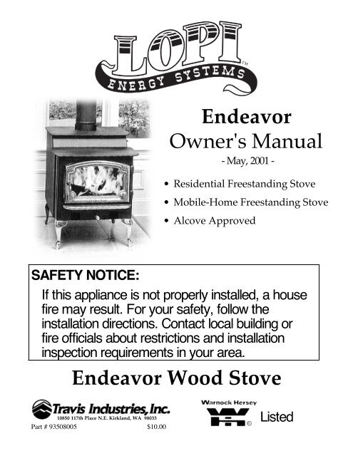
<strong>Endeavor</strong><br />
Owner's <strong>Manual</strong><br />
- May, 2001 -<br />
<strong>¥</strong> Residential Freestanding Stove<br />
<strong>¥</strong> Mobile-Home Freestanding Stove<br />
<strong>¥</strong> Alcove Approved<br />
SAFETY NOTICE:<br />
If this appliance is not properly installed, a house<br />
fire may result. For your safety, follow the<br />
installation directions. Contact local building or<br />
fire officials about restrictions and installation<br />
inspection requirements in your area.<br />
<strong>Endeavor</strong> Wood Stove<br />
10850 117th Place N.E. Kirkland, WA 98033<br />
Part # 93508005 $10.00 Listed
Introduction<br />
INTRODUCTION & IMPORTANT INFORMATION PAGE 1<br />
We welcome you as a new owner of a <strong>Lopi</strong> <strong>Endeavor</strong> wood-burning appliance. In purchasing a <strong>Lopi</strong><br />
<strong>Endeavor</strong> you have joined the growing ranks of concerned individuals whose selection of an energy<br />
system reflects both a concern for the environment and aesthetics. The <strong>Lopi</strong> <strong>Endeavor</strong> is one of the<br />
finest appliances the world over. This manual will explain the installation, operation, and maintenance<br />
of this appliance. Please familiarize yourself with the Owner's <strong>Manual</strong> before operating your appliance<br />
and save the manual for future reference. Included are helpful hints and suggestions which will make<br />
the installation and operation of your new appliance an easier and more enjoyable experience. We offer<br />
our continual support and guidance to help you achieve the maximum benefit and enjoyment from your<br />
appliance.<br />
Important Information<br />
No other <strong>Lopi</strong> <strong>Endeavor</strong> appliance has the same<br />
serial number as yours. The serial number is<br />
stamped onto the label on the back of the<br />
appliance.<br />
This serial number will be needed in case you<br />
require service of any type.<br />
Model: LOPI <strong>Endeavor</strong><br />
Serial Number:<br />
Purchase Date:<br />
Purchased From:<br />
Mail your Warranty Card Today, and Save<br />
Your Bill of Sale.<br />
To receive full warranty coverage, you will<br />
need to show evidence of the date you<br />
purchased your appliance. Do not mail your<br />
Bill of Sale to us.<br />
We suggest that you attach your Bill of Sale to<br />
this page so that you will have all the<br />
information you need in one place should the<br />
need for service or information occur.
PAGE 2 SAFETY PRECAUTIONS<br />
Mobile<br />
Home<br />
<strong>¥</strong> The viewing door must be<br />
closed and latched during<br />
operation.<br />
<strong>¥</strong> Never block free airflow<br />
through the air vents on<br />
this appliance.<br />
<strong>¥</strong> This appliance is designed<br />
and approved for the<br />
burning of cord wood<br />
only. Do not attempt to<br />
burn any other type of<br />
fuel other than cord wood<br />
in this appliance, it will<br />
void all warranties and<br />
safety listings.<br />
<strong>¥</strong> Do not touch the<br />
appliance while it is hot<br />
and educate all children of<br />
the danger of a hightemperature<br />
appliance.<br />
Young children should be<br />
supervised when they are<br />
in the same room as the<br />
appliance.<br />
<strong>¥</strong> This appliance must be<br />
properly installed to<br />
prevent the possibility of<br />
a house fire. The<br />
instructions must be<br />
strictly adhered to. Do<br />
not use makeshift<br />
methods or compromise<br />
in the installation.<br />
<strong>¥</strong> Inspect the chimney<br />
connector and chimney at<br />
least twice monthly and<br />
clean if necessary.<br />
Creosote may build up<br />
and cause a house fire.<br />
<strong>¥</strong> Do not connect this<br />
appliance to any chimney<br />
serving another appliance.<br />
<strong>¥</strong> When installed in a<br />
mobile home, this<br />
appliance must be bolted<br />
to the floor, have outside<br />
air, and not be installed in<br />
the bedroom (Per H.U.D.<br />
requirements). Check<br />
with local building<br />
officials.<br />
Gas<br />
Ashes<br />
Type<br />
HT<br />
36"<br />
Minimum<br />
Ok<br />
Clay<br />
Liner<br />
<strong>¥</strong> Gasoline or other<br />
flammable liquids must<br />
never be used to start the<br />
fire or "Freshen Up" the<br />
fire. Do not store or use<br />
gasoline or other<br />
flammable liquids in the<br />
vicinity of this appliance.<br />
<strong>¥</strong> Ashes must be disposed in<br />
a metal container with a<br />
tight lid and placed on a<br />
non-combustible surface<br />
well away from the home<br />
or structure.<br />
<strong>¥</strong> Keep furniture, drapes,<br />
curtains, wood, paper, and<br />
other combustibles a<br />
minimum of 36" away<br />
from the appliance.<br />
<strong>¥</strong> Contact your local<br />
building officials to<br />
obtain a permit and<br />
information on any<br />
installation restrictions or<br />
inspection requirements in<br />
your area. Notify your<br />
insurance company of this<br />
appliance as well.<br />
<strong>¥</strong> This appliance must be<br />
connected to a listed high<br />
temperature (HT)<br />
residential type chimney<br />
or an approved masonry<br />
chimney with a standard<br />
clay tile, or stainless steel<br />
liner.<br />
<strong>¥</strong> Do not place clothing or<br />
other flammable items on<br />
or near this appliance.
This<br />
<strong>Manual</strong><br />
<strong>¥</strong> Never try to repair or<br />
replace any part of this<br />
appliance unless<br />
instructions are given in<br />
this manual. All other<br />
work must be done by a<br />
trained technician.<br />
<strong>¥</strong> Allow the appliance to<br />
cool before carrying out<br />
any maintenance or<br />
cleaning.<br />
<strong>¥</strong> Maintain the door and<br />
glass seal and keep them<br />
in good condition.<br />
<strong>¥</strong> Avoid placing wood<br />
against the glass when<br />
loading. Do not slam the<br />
door or strike the glass.<br />
<strong>¥</strong> Do not throw this manual<br />
away. This manual has<br />
important operating and<br />
maintenance instructions<br />
that you will need at a<br />
later time. Always follow<br />
the instructions in this<br />
manual.<br />
SAFETY PRECAUTIONS (CONTINUED) PAGE 3<br />
<strong>¥</strong> Do not make any changes<br />
or modifications to an<br />
existing masonry fireplace<br />
or chimney to install this<br />
appliance.<br />
<strong>¥</strong> Do not make any changes<br />
to the appliance to<br />
increase combustion air.<br />
<strong>¥</strong> Overfiring the appliance<br />
may cause a house fire. If<br />
a unit or chimney<br />
connector glows, you are<br />
overfiring.<br />
<strong>¥</strong> Do not use a grate or<br />
other device to elevate the<br />
fire off of the firebox<br />
floor. Burn the fire<br />
directly on the bricks.<br />
<strong>¥</strong> Travis Industries, Inc.<br />
grants no warranty,<br />
implied or stated, for the<br />
installation or<br />
maintenance of your<br />
appliance, and assumes<br />
no responsibility of any<br />
consequential<br />
damage(s).
PAGE 4 TABLE OF CONTENTS<br />
General Information<br />
Introduction & Important Information.......................... 1<br />
Safety Precautions..................................................... 2<br />
Features & Specifications ........................................... 5<br />
Stove Installation<br />
Before You Begin....................................................... 6<br />
Planning The Installation............................................ 6<br />
Preparation for Installation.......................................... 6<br />
Stove Installation Considerations ............................... 6<br />
Stove Placement Requirements ................................ 7<br />
Floor Protection Requirements ................................... 7<br />
Optional Equipment Requirements ............................ 8<br />
Factory Built Chimney Requirements ........................ 8<br />
Chimney Termination Requirements .......................... 9<br />
Outside Air Requirements........................................... 9<br />
Alcove Installation Requirements ............................... 10<br />
Mobile Home Requirements ...................................... 11<br />
INSTALLATION DIAGRAMS<br />
Standard Ceiling with a Factory Built Chimney ..... 12<br />
Cathedral Ceiling with a Factory Built Chimney ... 12<br />
Exterior Factory Built Chimney.............................. 13<br />
Hearth Stove Positive Connection........................ 13<br />
Hearth Stove Direct Connection........................... 14<br />
Hearth Stove Horizontal Connection .................... 14<br />
Block-Off Plate Installation......................................... 15<br />
Operating Your Appliance<br />
Before You Begin....................................................... 16<br />
Paint Curing ............................................................... 16<br />
Location of Controls.................................................... 16<br />
Approximate Air Control Settings ......................... 16<br />
Bypass Control...................................................... 17<br />
Learning to Burn your Appliance................................ 17<br />
How to Start a Hot Fire Quickly ............................ 17<br />
How to Reload Your Appliance ............................ 18<br />
How to Adjust the Heat Output Precisely ............. 18<br />
How to Obtain an Overnight Burn ........................ 19<br />
Good Burning Habits ............................................ 19<br />
Blower Operation ....................................................... 20<br />
When to turn the blower on ................................... 20<br />
Blower controls..................................................... 20<br />
How to Use the Blower to Regulate Heat............. 20<br />
A Word about Wood ................................................... 21<br />
The Drier the Better............................................... 21<br />
How to Dry and Store Wood ................................. 21<br />
Constructing a Wood Shed .................................. 22<br />
What Type of Wood is Best................................... 22<br />
How to Buy Wood ................................................. 22<br />
Don't Burn Scraps, Garbage, Wax Logs, etc. ....... 22<br />
Maintaining Your Appliance<br />
Maintenance Schedule............................................... 23<br />
Remove Ash From The Firebox ................................. 23<br />
Clean The Viewing Glass........................................... 23<br />
Clean The Brass ........................................................ 23<br />
Check For Creosote Buildup...................................... 23<br />
Door And Glass Inspection ........................................ 24<br />
Adjusting the Door Cam ....................................... 24<br />
Replacing the Door Gasket .................................. 25<br />
Replacing the Glass or Glass Gasket................... 25<br />
Lubricate The Door Hinge.......................................... 25<br />
Touch-Up Paint .......................................................... 26<br />
Blower Cleaning ......................................................... 26<br />
Firebrick And Baffle Inspection And Cleaning............ 26<br />
Firebrick Removal and Replacement Inst. ........... 27<br />
Baffle Removal and Replacement Inst. ................ 27<br />
Replacement Parts List.............................................. 29<br />
Troubleshooting<br />
Troubleshooting Table ............................................... 30<br />
Warranty<br />
Warranty..................................................................... 31<br />
Listing Information<br />
Listing Information...................................................... 32<br />
Optional Equipment<br />
Stove Legs Installation ............................................... 33<br />
Pedestal Installation ................................................... 33<br />
Using Outside Air with the Pedestal ..................... 34<br />
Outside Air Boot Installation....................................... 34<br />
Rear Blower Installation ............................................. 35<br />
Index<br />
Index .......................................................................... 36
Installation Options:<br />
<strong>¥</strong> Freestanding<br />
<strong>¥</strong> Freestanding in an Alcove<br />
<strong>¥</strong> Freestanding in a Mobile Home<br />
<strong>¥</strong> Freestanding Hearth Stove<br />
Heating Specifications:<br />
FEATURES AND SPECIFICATIONS PAGE 5<br />
Features:<br />
<strong>¥</strong> EPA Phase II Approved<br />
<strong>¥</strong> 2.2 Cubic Foot Firebox Volume<br />
<strong>¥</strong> Single, Push/Pull Operating Control<br />
<strong>¥</strong> Accepts Logs Up to 18" Long<br />
<strong>¥</strong> Long Burn Time - Up to 10 Hours<br />
<strong>¥</strong> 5/16" and 3/16" Steel Plate Construction<br />
<strong>¥</strong> Heavy Duty Refractory Firebrick<br />
<strong>¥</strong> Optional High-Tech Blower<br />
Approximate Maximum Heating Capacity (in square feet)* 1,200 to 2,000<br />
Maximum BTU's per Hour (Cord Wood Calculation) 72,400<br />
Overall Efficiency (Oregon Method) 70.4%<br />
Maximum Burn Time (Hours) 10<br />
* Heating capacity will vary depending on the home's floor plan, degree of insulation, and the outside temperature. It is also<br />
affected by the quality and moisture level of the fuel.<br />
Dimensions:<br />
Flue Location:<br />
6" Diameter flue is<br />
centered on the<br />
stove and 5 3/4"<br />
from the back edge<br />
of the stove top.<br />
NOTE:<br />
Measure all<br />
clearances<br />
from the<br />
edge of the<br />
stove top.<br />
Width:<br />
Of Stove Top.......24"<br />
Weight:<br />
With Legs......448 Lbs.<br />
6" Flue Diameter (inside)<br />
Depth*:<br />
From Back Edge of Stove<br />
Top to Faceplate..........23 1/2"<br />
Ashlip Depth...................4 3/4"<br />
Height:<br />
From Base to Top.............22 3/4"<br />
With Black Steel Legs.......29 1/4"<br />
With Cast or Brass Legs....30 5/8"<br />
With Pedestal..................34 5/8"<br />
Emissions: 1.9 Grams Per Hour (EPA Phase II Approved) Ð Tests conducted by E.E.S.P.C. Lab.
PAGE 6 STOVE INSTALLATION<br />
SAFETY NOTICE:<br />
If this appliance is not properly installed, a house fire may result. For your safety,<br />
follow the installation directions. Contact local building or fire officials about<br />
restrictions and installation inspection requirements in your area.<br />
<strong>¥</strong> Check with local building officials for any permits required for installation of this stove and<br />
notify your insurance company before proceeding with installation.<br />
PLANNING THE INSTALLATION<br />
HINT: We suggest that you have an authorized Travis Industries dealer install your stove. If<br />
you install the stove yourself, your authorized dealer should review your plans for<br />
installation.<br />
This stove is approved for connection to either a factory-built chimney or existing masonry fireplace.<br />
Depending upon your installation concerns, a wide range of installation options are yours to provide the<br />
most desirable installation. The sections that follow detail the requirements that must be met for a safe<br />
installation. To further help installation, the six most common types of installations are explained in the<br />
section "Stove Installation Considerations". Prior to installing your stove make a detailed plan with<br />
dimensions to double-check them against all of the requirements listed.<br />
PREPARATION FOR INSTALLATION<br />
<strong>¥</strong> Check for damage to the exterior of the stove (dents should be reported, scratches can be fixed by<br />
applying touch up paint).<br />
<strong>¥</strong> Check the interior of the firebox (damaged firebrick must be replaced, displaced baffle parts<br />
must be aligned - see "Firebrick and Baffle Inspection and Cleaning" on pages 26 - 28).<br />
HINT: The stove can be lightened by removing the firebricks and baffle - see "Firebrick and<br />
Baffle Inspection and Cleaning" on pages 26 - 28.<br />
STOVE INSTALLATION CONSIDERATIONS<br />
The table below details the six most common types of installations along with considerations.<br />
Alternative methods of installation are available if they comply with local building codes.<br />
Installation Type Considerations<br />
Standard Ceiling with a Factory Built Chimney<br />
(Page 12)<br />
Cathedral Ceiling with a Factory Built Chimney<br />
(Page 12)<br />
Exterior Factory Built Chimney<br />
(Page 13)<br />
Hearth Stove Positive Connection<br />
(Page 13)<br />
Hearth Stove Direct Connection<br />
(Page 14)<br />
Hearth Stove Horizontal Connection<br />
(Page 14)<br />
<strong>¥</strong> Requires floor and roof penetration<br />
<strong>¥</strong> Provides best draft<br />
<strong>¥</strong> Cathedral style chimney support required<br />
<strong>¥</strong> Provides best draft<br />
<strong>¥</strong> Uses two elbows to route chimney outside<br />
<strong>¥</strong> Exterior chimney is hidden from the room<br />
<strong>¥</strong> For every 1' of horizontal run, you should have 8' of vertical<br />
chimney<br />
<strong>¥</strong> Elbows reduce draft<br />
<strong>¥</strong> Optional exterior chase reduces cold air blockage<br />
<strong>¥</strong> Utilizes existing masonry chimney<br />
<strong>¥</strong> Provides good draft due to full reline<br />
<strong>¥</strong> Easier to clean than direct or horizontal hearth stove<br />
<strong>¥</strong> Utilizes existing masonry chimney<br />
<strong>¥</strong> Requires construction of a "block-off plate" - Page 15<br />
<strong>¥</strong> Draft reduced due to elbows & chimney cross section<br />
<strong>¥</strong> Utilizes existing masonry chimney<br />
<strong>¥</strong> Draft is good because of vertical section above stove
STOVE INSTALLATION (CONT.) PAGE 7<br />
STOVE PLACEMENT REQUIREMENTS<br />
HINT: REDUCING CLEARANCES - Clearances may be reduced by methods specified in<br />
NFPA 211, listed wall shields, pipe shields, or other means approved by local<br />
building or fire officials.<br />
<strong>¥</strong> Stove must be placed so that no combustibles are within, or can swing within (e.g. drapes,<br />
doors), 36" of the front of the stove<br />
<strong>¥</strong> If the stove is placed in a location where the ceiling height is less than 7', it must follow the<br />
requirements in the section "Alcove Installation Requirements"<br />
<strong>¥</strong> Must maintain the following clearances to combustibles (drywall, furniture, etc.):<br />
Minimum Clearance<br />
Singlewall Reduced<br />
(See the illustration below) Connector Clearance*<br />
a Sidewall to stove 15" 13"<br />
b Backwall to stove 15" 4 1/4"<br />
c Cornerwall to stove 15" 6 1/2"<br />
d Connector to sidewall 24" 21 1/2"<br />
e Connector to backwall 17 3/4" 6 1/2"<br />
f Connector to cornerwall 24" 15"<br />
<br />
b e <br />
a<br />
<br />
d<br />
<br />
<br />
<br />
<br />
Rear<br />
heat<br />
shield<br />
Measure all clearances from the<br />
nearest edge of the stove top.<br />
<br />
c<br />
<br />
<br />
<br />
f<br />
c<br />
<br />
<br />
<br />
* Reduced clearance installations require one of the chimney systems listed below:<br />
<strong>¥</strong> AMERI-TEC model DCC with model HS chimney <strong>¥</strong> OLIVER MACLEOD Provent model PV connector with model 3103 chimney<br />
<strong>¥</strong> DURAVENT model DVL with DURA-PLUS chimney <strong>¥</strong> SECURITY model DP with SECURITY model ASHT or S2100 chimney<br />
<strong>¥</strong> GSW-Jakes Evans Superpipe 2100 (directly off appliance) <strong>¥</strong> SELKIRK METALBESTOS model DS connector with model SSII chimney<br />
<strong>¥</strong> Metalfab model DW connector with TG chimney <strong>¥</strong> Standard Masonry Chimney with any one of the above listed connectors<br />
<strong>¥</strong> I.C.C. Excel 103HT Chimney with Ultrablack HP Double-Wall connector<br />
NOTE: Reduced clearance connectors can not connect directly to the flue collar. Make sure to<br />
order an appliance adapter for the brand of connector being used.<br />
FLOOR PROTECTION REQUIREMENTS<br />
<strong>¥</strong> Must be non-combustible and at<br />
least .018" thick (26 gauge)<br />
<strong>¥</strong> Must extend 6" to the side and rear<br />
of the appliance<br />
<strong>¥</strong> Must extend 16" from the front<br />
(measure from the faceplate)<br />
<strong>¥</strong> Minimum 45" deep by 33 3/8" wide<br />
16" Minimum<br />
(from faceplate)<br />
6" Minimum<br />
(from rear of stove, not stove top or heat shield)<br />
Heat Shield<br />
Stove Top<br />
6" Minimum<br />
(from side of stove,<br />
not stove top)<br />
Floor Protection<br />
(Minimum .018" thick)
PAGE 8 STOVE INSTALLATION (CONT.)<br />
OPTIONAL EQUIPMENT REQUIREMENTS (See "Optional Equipment" on page 33)<br />
<strong>¥</strong> Must be installed with either the optional legs or pedestal<br />
FACTORY BUILT CHIMNEY REQUIREMENTS<br />
<strong>¥</strong> Chimney connector must be a minimum 24 MSG black or 26 MSG blued steel<br />
<strong>¥</strong> Use 6" diameter type HT chimney from one manufacturer (do not mix brands). Chimney must<br />
be used from the first floor or wall penetration to the chimney cap.<br />
<strong>¥</strong> Chimney connector and chimney must be fastened to the stove and each adjoining section<br />
<strong>¥</strong> Follow the chimney manufacturer's clearances and requirements<br />
<strong>¥</strong> Use the chimney manufacturer's fire stops, attic guards, roof supports, and flashings when<br />
passing through a ceiling (or thimble when passing through a combustible wall)<br />
<strong>¥</strong> Minimum height of 15 feet<br />
NOTE: External factors may adversely affect draft (see "Drafting Performance" below). In<br />
these cases additional chimney height may be required to boost draft.<br />
<strong>¥</strong> Maximum height of 33 feet<br />
<strong>¥</strong> No more than 180 o of elbows (two 90 o elbows, or two 45 o & one 90 o elbow, etc.)<br />
NOTE: Additional elbows may be allowed if draft is sufficient. Whenever elbows are used the<br />
draft is adversely affected. Additional chimney height may be required to boost draft.<br />
Drafting<br />
Performance<br />
Chimney Cap<br />
(See the section<br />
"Chimney Termination<br />
Requirements" for<br />
more details)<br />
Factory Built<br />
Chimney<br />
Sections<br />
Floor Penetration<br />
Equipment (Attic<br />
Radiation Shield with<br />
Chimney Support)<br />
Reduceced<br />
Clearance<br />
Chimney<br />
Connector<br />
Sections<br />
Floor<br />
Protection<br />
<br />
<br />
<br />
<br />
<br />
<br />
<br />
<br />
<br />
<br />
<br />
<br />
<br />
<br />
<br />
}<br />
<br />
}<br />
} Roof Penetration Equipment<br />
(Roof Radiation Shield,<br />
Flashing, Storm Collar)<br />
Minimum Air Space to<br />
Combustibles (See<br />
Chimney Manufacturer's<br />
Instructions - usually 2")<br />
Standard residential installations with<br />
reduced clearance connector may use the<br />
clearance determined by the manufacturer<br />
of the connector for the connector to wall<br />
clearance or the clearance listed in this<br />
manual.<br />
Mobile home installations must use the<br />
the reduced clearance connector<br />
clearances listed in this manual under<br />
ÒAdditional Requirements for Mobile Home<br />
InstallationsÓ.<br />
Stove Clearance<br />
(as outlined in this manual)<br />
Minimum System 15'<br />
Maximum System 33'<br />
This appliance relies upon natural draft to operate. External forces, such as wind,<br />
barometric pressure, topography, or factors of the home (negative pressure from exhaust<br />
fans, chimneys, air infiltration, etc.), may adversely affect draft. Travis Industries can<br />
not be responsible for external forces leading to less than optimal performance.
STOVE INSTALLATION (CONT.) PAGE 9<br />
CHIMNEY TERMINATION REQUIREMENTS<br />
<strong>¥</strong> Must have an approved cap (to prevent water from entering)<br />
<strong>¥</strong> Must not be located where it will become plugged by snow or other material<br />
<strong>¥</strong> Must terminate at least 3' above the roof and at least 2' above any portion of the roof within 10'<br />
Slanted Roofs<br />
Flat Roofs<br />
Chimney must<br />
extend 3'<br />
above the roof<br />
Chimney must<br />
extend 3'<br />
above the roof<br />
Chimney must extend 2'<br />
above any portion of the roof<br />
within 10' of the chimney<br />
Chimney must extend 2'<br />
above any portion of the roof<br />
within 10' of the chimney<br />
OUTSIDE AIR REQUIREMENTS<br />
<strong>¥</strong> Required for mobile homes & in certain localities (check with building officials)<br />
<strong>¥</strong> Must not be drawn from an enclosed space (garage, unventilated crawl space)<br />
<strong>¥</strong> Requires the optional pedestal or outside air boot with legs (installation instructions are in the<br />
optional equipment section at the rear of this manual)<br />
Pedestal (with insulation)<br />
directs air to the stove.<br />
Air may be drawn from a ventilated<br />
crawl space or use an air duct.<br />
When using outside air, find a location where the chimney and<br />
outside air hole do not interfere with structural members of the home.<br />
A hole must be cut<br />
through the floor<br />
protection and<br />
floor and the<br />
rodent screen<br />
nailed in place<br />
here (see the<br />
optional equipment<br />
instructions for<br />
exact sizes)<br />
Outside<br />
Air Boot<br />
Optional Air Duct (must not be<br />
longer than 15' and at least 16<br />
square inches in cross section)<br />
Outside air entrance must be placed so<br />
it does not become blocked by snow.<br />
NOTE: If the duct is less than 5 feet long, the cross section may be a min. 12 square inches.<br />
HINT: When using outside air find a location where the chimney and outside air inlet avoid<br />
the structural members (i.e.: floor joists and roof beams) of the home.
PAGE 10 STOVE INSTALLATION (CONT.)<br />
ALCOVE INSTALLATION REQUIREMENTS<br />
Whenever the stove is placed in a location where the ceiling height is less than 7' tall, it is considered an<br />
alcove installation. Because of the reduced height, the special installation requirements listed below<br />
must be met.<br />
<strong>¥</strong> Chimney connector and chimney must be one of the following types:<br />
<strong>¥</strong> AMERI-TEC model DCC with model HS chimney <strong>¥</strong> OLIVER MACLEOD Provent model PV connector with model 3103 chimney<br />
<strong>¥</strong> DURAVENT model DVL with DURA-PLUS chimney <strong>¥</strong> SECURITY model DP with SECURITY model ASHT or S2100 chimney<br />
<strong>¥</strong> GSW-Jakes Evans Superpipe 2100 (directly off appliance) <strong>¥</strong> SELKIRK METALBESTOS model DS connector with model SSII chimney<br />
<strong>¥</strong> Metalfab model DW connector with TG chimney <strong>¥</strong> Standard Masonry Chimney with any one of the above listed connectors<br />
<strong>¥</strong> I.C.C. Excel 103HT Chimney with Ultrablack HP Double-Wall connector<br />
NOTE: Reduced clearance connectors can not connect directly to the flue collar. Make sure to<br />
order an appliance adapter for the brand of connector being used.<br />
<strong>¥</strong> Alcoves are classified as combustible or non-combustible. Non-combustible alcoves must have<br />
walls and a ceiling that are 3 1/2" thick of a non-combustible material (brick, stone, or concrete).<br />
This non-combustible material must be spaced and ventilated at least 1" off of all combustible<br />
materials (walls, ceiling, etc.) to allow air to move around the non-combustible walls and ceiling.<br />
All other alcoves are considered combustible. The clearances below must be met:<br />
Minimum Clearance<br />
Combustible Non-Combustible<br />
(See the illustration below)<br />
Alcove<br />
Alcove<br />
A Sidewall to stove 15" 6"<br />
B Backwall to stove 7 1/2" 2"<br />
D Connector to sidewall 23 1/2" 14 1/2"<br />
E Connector to backwall 9 3/4" 4 1/4"<br />
G Maximum depth of alcove 48" 48"<br />
H Minimum width of alcove 54" 36"<br />
J Minimum height of alcove 84" 6" above stove top<br />
Non-combustible alcove<br />
construction (on walls<br />
and ceiling) - see the<br />
explanation above.<br />
Ventilated<br />
air space<br />
1" Min.<br />
Combustible<br />
materials<br />
3 1/2" thick<br />
non-combustible<br />
material<br />
Non-combustible<br />
reinforcer<br />
J<br />
A<br />
D<br />
H<br />
E<br />
B<br />
G
STOVE INSTALLATION (CONT.) PAGE 11<br />
MOBILE HOME REQUIREMENTS<br />
The <strong>Endeavor</strong> is approved for installation into a mobile home if the requirements listed below are met in<br />
addition to the normal requirements:<br />
<strong>¥</strong> Outside air must be installed - see "Outside Air Requirements" on page 9<br />
<strong>¥</strong> The appliance must be bolted to the floor (The optional pedestal provides the equipment needed<br />
to do this - see "Pedestal Installation" on page 33)<br />
<strong>¥</strong> The appliance must be grounded to the chassis of the mobile home (some states do not require<br />
this Ð check with local building officials)<br />
<strong>¥</strong> The appliance must not be located in the bedroom of a mobile home (some states do not require<br />
this Ð check with local building officials)<br />
<strong>¥</strong> Chimney connector and chimney must be one of the following types:<br />
<strong>¥</strong> AMERI-TEC model DCC with model HS chimney <strong>¥</strong> OLIVER MACLEOD Provent model PV connector with model 3103 chimney<br />
<strong>¥</strong> DURAVENT model DVL with DURA-PLUS chimney <strong>¥</strong> SECURITY model DP with SECURITY model ASHT or S2100 chimney<br />
<strong>¥</strong> GSW-Jakes Evans Superpipe 2100 (directly off appliance) <strong>¥</strong> SELKIRK METALBESTOS model DS connector with model SSII chimney<br />
<strong>¥</strong> Metalfab model DW connector with TG chimney <strong>¥</strong> Standard Masonry Chimney with any one of the above listed connectors<br />
<strong>¥</strong> I.C.C. Excel 103HT Chimney with Ultrablack HP Double-Wall connector<br />
NOTE: Reduced clearance connectors can not connect directly to the flue collar. Make sure to<br />
order an appliance adapter for the brand of connector being used.<br />
<strong>¥</strong> Stove placement must maintain the following clearances to combustibles (drywall, furniture, etc.)<br />
Minimum Clearance(See the illustration below)<br />
a Sidewall to stove 15"<br />
b Backwall to stove 6"<br />
c Cornerwall to stove 6 1/2"<br />
d Connector to sidewall 23 1/2"<br />
e Connector to backwall 8 1/4"<br />
f Connector to cornerwall 15"<br />
<br />
b e <br />
a<br />
<br />
d<br />
<br />
<br />
<br />
<br />
Rear<br />
heat<br />
shield<br />
Measure all clearances from the<br />
nearest edge of the stove top.<br />
<br />
c<br />
<br />
<br />
<br />
f<br />
c
PAGE 12 STOVE INSTALLATION (CONT.)<br />
STANDARD<br />
CEILING WITH<br />
A FACTORY<br />
BUILT<br />
CHIMNEY<br />
CATHEDRAL<br />
CEILING WITH<br />
A FACTORY<br />
BUILT<br />
CHIMNEY<br />
Chimney Cap<br />
(See the section "Chimney<br />
Termination Requirements"<br />
for more details)<br />
Chimney Sections<br />
Insulation<br />
Follow the chimney<br />
manufacturer's instructions<br />
and clearances for floor<br />
penetrations. A chimney<br />
support is required, an attic<br />
insulation shield is required<br />
where insulation is present.<br />
Chimney Connector Sections<br />
Floor Protection<br />
(See the section "Floor<br />
Protection Requirements"<br />
for more details)<br />
Chimney Cap<br />
(See the section "Chimney<br />
Termination Requirements"<br />
for more details)<br />
Chimney Sections<br />
Minimum Air Space to<br />
Combustibles (See<br />
Chimney Manufacturer's<br />
Instructions - usually 2")<br />
Chimney Connector Sections<br />
Floor Protection<br />
(See the section "Floor<br />
Protection Requirements"<br />
for more details)<br />
}<br />
}<br />
}<br />
Follow the chimney<br />
manufacturer's instructions<br />
and clearances for roof<br />
penetrations. A storm<br />
collar and flashing are<br />
required (some require a<br />
radiation shield).<br />
Minimum Air Space to<br />
Combustibles (See<br />
Chimney Manufacturer's<br />
Instructions - usually 2")<br />
Minimum 15'<br />
Maximum 33'<br />
Stove Clearances<br />
(See the section "Stove<br />
Placement Requirements"<br />
for more details)<br />
Follow the chimney<br />
manufacturer's instructions<br />
and clearances for roof<br />
penetrations. A storm<br />
collar, flashing, and<br />
cathedral-style chimney<br />
support are required (some<br />
require a radiation shield).<br />
Minimum 15'<br />
Maximum 33'<br />
Stove Clearances<br />
(See the section "Stove<br />
Placement Requirements"<br />
for more details)
EXTERIOR<br />
FACTORY<br />
BUILT<br />
CHIMNEY<br />
NOTE:<br />
Exterior<br />
chimneys are<br />
subject to<br />
greater<br />
moisture and<br />
creosote<br />
accumulation<br />
due to the<br />
lower<br />
temperatures.<br />
An insulated<br />
chase will<br />
reduce these<br />
accumulations<br />
(the proper<br />
clearances to<br />
the chimney<br />
must be<br />
maintained).<br />
HEARTH<br />
STOVE<br />
POSITIVE<br />
CONNECTION<br />
NOTE:<br />
Most factorybuilt<br />
chimney<br />
manufacturers<br />
make stainless<br />
steel chimney<br />
liners, either<br />
flexible or<br />
rigid. This<br />
provides a<br />
wide variety of<br />
installation<br />
options. Make<br />
sure to follow<br />
the<br />
manufacturer's<br />
instructions for<br />
installation<br />
and support.<br />
Chimney Cap<br />
(See the section "Chimney<br />
Termination Requirements"<br />
for more details)<br />
Chimney Sections<br />
Minimum Air Space to<br />
Combustibles (See<br />
Chimney Manufacturer's<br />
Instructions - usually 2")<br />
Min. 18" clearance<br />
to ceiling<br />
Chimney Connector<br />
Sections<br />
Floor Protection<br />
(See the<br />
section "Floor<br />
Protection<br />
Requirements"<br />
for more<br />
details)<br />
Combustible<br />
Mantle<br />
Wall Bands<br />
and Supports<br />
NOTE: The entire fireplace,<br />
including chimney, must be clean<br />
and not cracked or damaged.<br />
Any damage must be repaired<br />
prior to installation of the insert.<br />
Chimney must be at least 15' tall<br />
and no greater than 33' tall.<br />
Entire fireplace, including<br />
chimney, must meet local<br />
building requirements.<br />
Floor Protection<br />
(See the section<br />
"Floor Protection<br />
Requirements"<br />
for more details)<br />
Min. 18"<br />
STOVE INSTALLATION (CONT.) PAGE 13<br />
} }<br />
}<br />
Follow the chimney<br />
manufacturer's<br />
instructions and<br />
clearances for roof<br />
penetrations. A storm<br />
collar and flashing are<br />
required (some require<br />
a radiation shield).<br />
Minimum 15'<br />
Maximum 33'<br />
You should have at<br />
least 8' of vertical<br />
chimney for every 1'<br />
of horizontal run.<br />
Insulated Tee<br />
Follow the chimney<br />
manufacturer's<br />
instructions and<br />
clearances for wall<br />
penetrations. A wall<br />
radiation shield<br />
(thimble) is required.<br />
Stove Clearances<br />
(See the section "Stove<br />
Placement Requirements" Optional<br />
for more details)<br />
insulated chase<br />
Cap (prevents water<br />
from entering)<br />
Flue Liner<br />
The liner must be<br />
stainless steel connector<br />
or flexible vent. Follow<br />
the liner manufacturer's<br />
instructions for<br />
installation and support.<br />
Airtight Insulated<br />
Clean-Out<br />
Remove damper<br />
or wire it open<br />
See the section<br />
"Stove Placement<br />
Requirements" for<br />
minimum clearances<br />
required.
PAGE 14 STOVE INSTALLATION (CONT.)<br />
HEARTH<br />
STOVE DIRECT<br />
CONNECTION<br />
NOTE:<br />
Direct<br />
connections<br />
require<br />
installation of<br />
an airtight<br />
block-off plate<br />
or damper<br />
adapter (see<br />
the section<br />
"Block-off<br />
Plate<br />
Installation"<br />
on page 18).<br />
HEARTH<br />
STOVE<br />
HORIZONTAL<br />
CONNECTION<br />
NOTE:<br />
This type of<br />
installation<br />
requires a wall<br />
radiation<br />
shield<br />
(thimble).<br />
Either close<br />
off and seal<br />
the damper,<br />
install a blockoff<br />
plate or<br />
install a<br />
damper<br />
adapter (see<br />
the section<br />
"Block-off<br />
Plate<br />
Installation"<br />
on page 15).<br />
NOTE: The chimney must<br />
have a clay tile liner. If it<br />
does not, the installation must<br />
use a positive connection (full<br />
reline). Entire fireplace,<br />
including chimney, must be<br />
clean and not cracked or<br />
damaged. Any damage must<br />
be repaired prior to<br />
installation of the insert.<br />
Chimney must be at least 15'<br />
tall and no greater than 33'<br />
tall. Entire fireplace,<br />
including chimney, must meet<br />
local building requirements.<br />
Floor Protection<br />
(See the section<br />
"Floor Protection<br />
Requirements" for<br />
more details)<br />
NOTE: The chimney<br />
must have a clay tile<br />
liner. If it does not, the<br />
installation must use a<br />
positive connection (full<br />
reline). Entire fireplace,<br />
including chimney, must<br />
be clean and not cracked<br />
or damaged. Any damage<br />
must be repaired prior to<br />
installation of the insert.<br />
Chimney must be at least<br />
15' tall and no greater<br />
than 33' tall. Entire<br />
fireplace, including<br />
chimney, must meet local<br />
building requirements.<br />
Floor Protection<br />
(See the section<br />
"Floor Protection<br />
Requirements"<br />
for more details)<br />
Min. 18"<br />
Min. 18"<br />
clearance<br />
to ceiling<br />
Chimney<br />
connector<br />
sections<br />
Combustible<br />
Mantle<br />
Block-off plate or<br />
damper adapter<br />
Combustible<br />
Mantle<br />
See the section<br />
"Stove Placement<br />
Requirements" for<br />
minimum clearances<br />
required.<br />
Flue Liner<br />
Stainless steel<br />
chimney connector<br />
must Extend 1' past<br />
the block-off plate<br />
or to the flue liner<br />
Remove<br />
damper<br />
or wire it<br />
open<br />
Airtight<br />
Insulated<br />
Clean-Out<br />
See the section<br />
"Stove Placement<br />
Requirements" for<br />
minimum clearances<br />
required.<br />
Flue Liner<br />
Follow the chimney<br />
manufacturer's<br />
instructions and<br />
clearances for wall<br />
penetrations. A wall<br />
radiation shield<br />
(thimble) is required.<br />
Airtight<br />
Insulated<br />
Clean-Out<br />
Either close off and<br />
seal the damper,<br />
install a block-off<br />
plate, or install a<br />
damper adapter.
STOVE INSTALLATION (CONT.) PAGE 15<br />
BLOCK-OFF PLATE INSTALLATION<br />
Whenever this appliance is installed as a direct connection a block-off plate or other non-combustible<br />
seal-off device (e.g. damper adapter) will need to be installed. This device is used to seal the chimney,<br />
insuring no smoke enters the home and providing the chimney system with a seal to provide greater<br />
draft. The directions below detail the steps for construction and installation of a block-off plate.<br />
1. Determine a location for the block-off plate at the top of the firebox below the damper area<br />
(make it high enough to allow installation of the connection pipe). The location should be level<br />
and in an area where it can be mounted easily. Measure the width at the rear ("A") and front<br />
("B") of the firebox at the height where the block-off plate will be installed (see the illustration<br />
below). Then measure the depth of the location where the block-off plate will be installed ("C").<br />
2. Make a cardboard template of the measurements, but add a 2" flange to each side. This flange<br />
will be used to mount the block-off plate to the inside of the firebox. Bend the flanges<br />
downwards on the template and place it inside the fireplace. If the template fits correctly in its<br />
planned location, go to the next step. If it does not, make a new template with the appropriate<br />
corrections until it fits correctly.<br />
3. With the template in place, mark the location that is centered in the fireplace where the flue will<br />
exit. This location approximates the center of the flue when the insert is in place (a slight offset<br />
may occur based upon insert and block-off plate placement). Remove the template and cut a 6<br />
1/4" diameter hole centered on this mark.<br />
4. Make the block-off plate of 24 gage or thicker steel to match the template. Drill two holes in<br />
each flange for mounting the plate.<br />
5. Mount the block-off plate using the appropriate screws. Masonry screws must be used for<br />
mounting a block-off plate in a masonry fireplace.<br />
6. Insulate the block-off plate using high-temperature fiberglass insulation (Kaowool® or<br />
equivalent) and furnace cement (allow the cement to dry for at least 24 hours before burning).<br />
7. After placing the appliance and installing the pipe through the block-off plate, use hightemperature<br />
fiberglass insulation and furnace cement to seal any cracks between the pipe and<br />
block-off plate.<br />
The center of<br />
the flue is 9<br />
1/4" back from<br />
the fireplace<br />
opening.<br />
B<br />
C<br />
Firebox<br />
Damper<br />
A<br />
2" Flanges<br />
(for attaching<br />
the block-off<br />
plate)<br />
Block-Off Plate Template<br />
Measurement<br />
"A"<br />
Measurement "B"<br />
Mark the location where the flue exits (6<br />
1/4" in diameter).<br />
Measurement<br />
"C"
PAGE 16 OPERATING YOUR APPLIANCE<br />
SAFETY NOTICE:<br />
If this appliance is improperly operated , a house fire may result. For your safety,<br />
read the directions below and the Safety Precautions listed on pages 2 and 3 prior<br />
to operating this appliance.<br />
<strong>¥</strong> If you have any questions regarding the operation of this appliance, contact your dealer.<br />
! Building a fire in disregard of the information provided in this section can cause permanent damage<br />
to your appliance and void your warranty.<br />
! Never use gasoline, lantern fuel, kerosene, charcoal lighter fluid, or similar liquids to start of<br />
"freshen up" a fire in this appliance. Keep these liquids well away from the appliance.<br />
! Keep furnishings and other combustible materials away from the appliance.<br />
PAINT CURING<br />
The paint on this stove cures under heat. Start a small fire and burn at a low rate for the first fire. You<br />
will notice fumes and smoke from the paint curing and oil burning off the steel. This is normal. We<br />
recommend you open windows to vent the room.<br />
ASH REMOVAL<br />
Ashes should be placed in a metal container with a tight fitting lid. The closed container of ashes should<br />
be placed on a noncombustible floor or on the ground, away from all combustible materials, pending<br />
final disposal. Ashes should be retained in the closed container until all cinders have thoroughly cooled.<br />
LOCATION OF CONTROLS<br />
DOOR HANDLE<br />
Slide out to allow<br />
more air into the<br />
firebox, for a<br />
faster rate of<br />
burn<br />
To open, turn the handle<br />
counter-clockwise and<br />
swing the door forward.<br />
Slide in to close<br />
down the amount<br />
of air into the<br />
firebox, for a<br />
slower rate<br />
of burn<br />
1.<br />
2.<br />
AIR CONTROL<br />
BYPASS<br />
CONTROL<br />
Pull the bypass out<br />
for loading & starting.<br />
Push the bypass in<br />
during burning.<br />
<strong>¥</strong> Do not open the door when the air control is closed. This may result in a sudden flash of flames as<br />
the fire ignites with oxygen. However, this appliance has been designed to reduce this possibility.<br />
<strong>¥</strong> The controls become hot during operation Ð use a glove or other device if necessary.<br />
<strong>¥</strong> Open the door for refueling only, do not operate with the door open or removed.<br />
Approximate Air Control Settings: Overnight Burn .....................<br />
Medium Burn........................<br />
Medium High Burn...............<br />
High Burn..............................<br />
Fully in to 1/8" open<br />
1/8" open to 5/8" open<br />
5/8" open to fully open<br />
Fully open (pulled out)
OPERATING YOUR APPLIANCE (CONTINUED) PAGE 17<br />
Bypass Control<br />
The bypass control is located on the right side of the stove near the top and is operated by pushing or<br />
pulling the control to the left or right. When the control is completely pulled out, the bypass allows the<br />
smoke to go directly up the flue, creating more draft for starting the stove or for reloading. When it is<br />
pushed in, the smoke must go around the baffle which utilizes secondary combustion and makes the<br />
stove more efficient (see the illustration below).<br />
Bypass Pulled Out-<br />
Used for Starting<br />
and Re-Loading<br />
Bypass Pushed In-<br />
Used for Normal Operation<br />
(Utilizes Secondary Combustion)<br />
LEARNING TO BURN YOUR APPLIANCE<br />
Using a wood-burning appliance takes some getting used to. Once you become accustomed to operating<br />
your appliance, you will be able to start a hot fire quickly, adjust the heat output precisely, and obtain<br />
overnight burns easier. Experienced wood burners may not need the information below, but may be able<br />
to re-affirm their skills by reading the following. The better you understand your appliance, the more<br />
rewarding you will find it.<br />
How to Start a Hot Fire Quickly<br />
Your wood-burning appliance acts much like an engine - before it will work at its best, it needs to reach<br />
a high temperature. The most common mistake in starting a fire is to use too little kindling, closing the<br />
bypass too soon, or turning the air control down too early. For good results, YOU MUST OBTAIN AN<br />
INTENSE FIRE BEFORE CLOSING THE AIR CONTROL DOWN. The steps below detail one<br />
method for starting a fire.<br />
1. Pile several pieces of kindling on top of newspaper or a fire starter in the center of the firebox (it<br />
is better to have too much kindling than not enough). Place two medium sized pieces of wood on<br />
either side of kindling laying front to back.<br />
2. Make sure the air control is fully open (pull all the way out) and the bypass opened (pull all the<br />
way out). Start the newspaper or fire starter. Note: you may want to crack the door during<br />
starting to allow for more air.<br />
3. Allow the kindling to start and burn. Then place another medium size piece of wood on top of<br />
the burning kindling so that it straddles the two medium pieces and close the door. This<br />
arrangement takes advantage of the air inlet located in the center under the door to feed the fire<br />
with adequate oxygen. You may notice the flames burning from the front to the back.<br />
4. Let the fire burn at least 15 minutes before closing the bypass. Wait at least 30 minutes or until<br />
the appliance is fully hot before closing the air control down.<br />
1. 2. 3.<br />
4.
PAGE 18 OPERATING YOUR APPLIANCE (CONTINUED)<br />
How to Reload Your Appliance<br />
When reloading your appliance, you can avoid smoke entering the room by following the steps below:<br />
1. Pull the air control all the way out so the fire starts to burn quickly, helping draft.<br />
2. Pull the bypass out all the way and wait 30 seconds to establish a strong draft.<br />
3. Open the door one inch and let air enter the appliance for a few seconds.<br />
4. Carefully place the new wood on top of the existing fire. Close the door and shut the bypass by<br />
pushing it all the way in. Let the fire burn on high for at least 20 minutes before turning it down<br />
Ð this will reduce creosote build-up.<br />
1.<br />
3.<br />
AIR CONTROL<br />
Open the door 1"<br />
and let air enter<br />
the appliance for<br />
a few seconds<br />
BYPASS<br />
CONTROL<br />
How to Adjust the Heat Output Precisely<br />
One complaint from wood-burning appliance owners is controlling the heat output to obtain a consistent<br />
room temperature. The reason for this is the inherent lag time between adjusting the air control and the<br />
change in heat output. Simply put, if you turn a hot appliance down now, it will continue to put off high<br />
amounts of heat for an additional 15 minutes. To obtain consistent room temperature, think ahead.<br />
When the room is starting to warm, and is almost up to the right temperature, turn the appliance down.<br />
If you utilize an optional blower, turn it on and off to increase or decrease room temperature. If you find<br />
the appliance must be turned down often, burn smaller, more intense fires instead. Although this means<br />
more reloadings, it will reduce creosote build-up and give a more consistent heat output.<br />
2.<br />
4.
OPERATING YOUR APPLIANCE (CONTINUED) PAGE 19<br />
How to Obtain an Overnight Burn<br />
An overnight burn of 10 hours may be obtained with a small amount of coals left over in the morning if<br />
the right steps are taken.<br />
1. Establish a hot fire.<br />
2. Fill the appliance with large pieces of wood, preferably hardwoods like oak or maple.<br />
3. Let the wood burn on high for 20 to 30 minutes to allow the new pieces of wood to catch fire and<br />
burn off any moisture.<br />
4. Push the air control in to a low setting. HINT: You want an air control position that is the<br />
farthest out, yet still allows coals to be left in the morning. Experiment using air control<br />
positions that are farther and farther out until a suitable position is found.<br />
5. In the morning, break down the coals and lay kindling and small pieces of wood on top of the<br />
coals to re-establish the fire. NOTE: Even the smallest amount of coals can start a new fire<br />
easily because of all the heat energy stored in the firebrick. If there are no coals left, yet the<br />
appliance is hot, you will find starting a new fire will be much easier and the appliance will start<br />
giving off heat much quicker than if started cold.<br />
Let the appliance burn at least 20 minutes on<br />
high after loading. This allows the appliance to<br />
reach the most efficient operating temperature.<br />
Even the smallest amount of<br />
coals can re-start the appliance.<br />
Good Burning Habits<br />
Increased efficiency, reduced emissions, and less creosote are the rewards of good burning habits.. The<br />
items below list good habits to establish with your new appliance.<br />
<strong>¥</strong> Get the appliance hot before turning it down<br />
<strong>¥</strong> Use smaller pieces of wood during start-up and high burns to increase temperature<br />
<strong>¥</strong> Use larger pieces of wood for overnight or sustained burns<br />
<strong>¥</strong> Stack the wood tightly together to establish a longer burn<br />
<strong>¥</strong> Leave a bed of ashes (1/2" deep) to allow for longer burns<br />
<strong>¥</strong> Be considerate of neighbors & the environment: burn dry wood only<br />
<strong>¥</strong> Burn small, intense fires instead of large, slow burning fires when possible<br />
<strong>¥</strong> Learn your appliance's operating characteristics to obtain optimum performance<br />
NOTE: A stove thermometer gives you a good indication of how hot your appliance is burning when<br />
placed directly on top of the appliance. Low burn is approximately 300 degrees F., medium<br />
burn 500 to 600 degrees F., and high burn 700 to 800 degrees F.
PAGE 20 OPERATING YOUR APPLIANCE (CONTINUED)<br />
BLOWER OPERATION<br />
The optional blower assists the convection chamber in distributing heat to your home. The directions<br />
below detail operation.<br />
Automatic Control<br />
The optional blower has a temperature-sensing device to automatically enable the blower once the<br />
appliance reaches a hot temperature. It also shuts the blower off once the appliance has cooled.<br />
When to turn the blower on<br />
The blower should be left on the off position for the first 30 minutes of starting the appliance.<br />
Blower controls<br />
The control knob is located on the control box attached to the cord leading from the blower. It is<br />
operated in the manner illustrated below.<br />
OFF<br />
Turn the knob<br />
all the way<br />
counter-<br />
clockwise to<br />
turn off.<br />
HIGH<br />
Turn the knob<br />
clockwise from<br />
the off position<br />
until it clicks.<br />
LOW<br />
Turn the knob<br />
all the way<br />
clockwise to<br />
turn to low.<br />
How to Use the Blower to Regulate Heat<br />
Turn the blower on if the room needs heat and the appliance is up to temperature. When the room has<br />
reached a high enough temperature, turn the blower off to stop the heat transfer. Used in conjunction<br />
with the air control, a steady temperature can be achieved.
OPERATING YOUR APPLIANCE (CONTINUED) PAGE 21<br />
A WORD ABOUT WOOD<br />
This appliance is designed to burn natural cord wood with high efficiencies and low emissions. With<br />
properly dried wood, you will fully realize the heating and clean-burning potential of our hightechnology<br />
appliance. With poor wood, this high-technology appliance will become much less efficient<br />
and produce more emissions. Read on to find out more about the type of fuel you should use.<br />
The Drier the Better<br />
The most common mistake made by<br />
wood-burners is using wet, green, or<br />
un-seasoned fuel. Ask any<br />
experienced wood-burner, and he or<br />
she will tell you the importance of<br />
dry wood. The reason is this: wet,<br />
green, or un-seasoned wood still has<br />
water in it. When the wood burns it<br />
must use its heat energy to evaporate<br />
the water. This robs your home of<br />
heat (it also leads to greater smoke<br />
and creosote due to lesser firebox<br />
temperatures). Dry wood usually has<br />
cracks in the grain. It will also be<br />
lighter and when two pieces are<br />
knocked together a crisp "knock" will<br />
be heard, not a dull "thud". When<br />
burning green, wet, or unseasoned<br />
wood you may notice difficulty in<br />
lighting, and water bubbling out of<br />
the grain when it becomes hot.<br />
Wet Wood<br />
Less Heat<br />
Leads<br />
To<br />
More Smoke<br />
& Creosote<br />
Leads<br />
To<br />
Dry Wood<br />
More Heat<br />
Leads<br />
To<br />
Leads<br />
To<br />
Less Smoke<br />
& Creosote<br />
How to Dry and Store Wood<br />
Aging is the only economical method for drying wood. Follow the steps below to dry and store wood:<br />
1. Make sure the wood is split into quarters and is no longer than 18" long (Hint: if you cut trees in<br />
summer, leave the leaves on for a week, this will draw moisture from the wood to dry it quicker).<br />
2. Stack the wood in loose piles that are covered and off the ground (this is to allow air to pass over<br />
each piece of wood Ð promoting faster drying) If no shelter is built, place clear polyethylene<br />
plastic over the wood (at an angle to allow moisture to run off). Let dry for at least one year.<br />
3. Store the wood in a dry location, preferably outside to prevent insects and dirt from entering the<br />
home. When needed, move small loads inside where the added heat will promote further drying.<br />
Cut the wood to 18"<br />
or less lengths and<br />
chop into quarters<br />
before stacking<br />
Prevailing<br />
Winds<br />
Keep the<br />
wood off<br />
the ground<br />
to increase<br />
air flow<br />
Air Flow<br />
Cover with 4 mil<br />
Polyethylene Air Flow<br />
Air Flow<br />
Stack the<br />
wood<br />
loosely to<br />
allow for<br />
air flow<br />
between<br />
the<br />
pieces
PAGE 22 OPERATING YOUR APPLIANCE (CONTINUED)<br />
A WORD ABOUT WOOD (CONTINUED)<br />
Constructing a Wood Shed<br />
The drawing to the right details the<br />
construction of an inexpensive wood shed<br />
that will promote drying, increasing the<br />
heat output from your wood.<br />
Sheet Metal Roofing<br />
3' Depth<br />
2x6x12 Rafter<br />
4x4x2 Posts Spaced 8' Apart<br />
8' Width<br />
2x8x8' Girder<br />
2x4 Purlins<br />
Siding and Girts<br />
(Optional)<br />
What Type of Wood is Best<br />
Choosing the kind of firewood to burn in your appliance depends on what is available to you.<br />
Softwoods, such as pine or fir ignite and burn quicker, but require more frequent loadings and are less<br />
suited for overnight burns. For longer burns, with less frequent loadings, we recommend harder woods<br />
such as oak or maple. The chart below details the BTU (heat) output of the various species. Note the<br />
higher BTU output of the harder woods. The best arrangement is to have softwoods for starting and<br />
immediate heating and hardwoods for overnight and sustained burns.<br />
SPECIES<br />
(20% moisture)<br />
LBS./CORD<br />
(Approximate)<br />
BTU's/CORD<br />
(Approximate)<br />
Hours per Cord at 40,000 BTU's per Hour<br />
(Approximate)<br />
ALDER 2540 19,050,000 476<br />
APPLE 4400 33,000,000 825<br />
ASH 3440 25,800,000 645<br />
BIRCH 3040 22,800,000 705<br />
CEDAR 2060 15,450,000 386<br />
COTTONWOOD 2160 16,200,000 405<br />
DOGWOOD 4320 31,725,000 793<br />
ELM 2260 16,950,000 423<br />
FIR, DOUGLAS 2970 22,275,000 556<br />
HEMLOCK 2700 20,250,000 506<br />
MAPLE 3200 24,000,000 600<br />
OAK, RED 3680 27,600,000 690<br />
OAK, WHITE 4200 31,500,000 787<br />
PINE 2250 16,875,000 421<br />
REDWOOD 2400 18,000,000 450<br />
SPRUCE 2240 16,800,000 420<br />
How to Buy Wood<br />
Wood is sold by the cord (4' wide by 4' high by 8' long). Buy wood in the spring and summer, when<br />
prices are lower and it will have plenty of time to dry. If buying in winter, have the wood moisture<br />
tested (test several pieces). You will receive up to 25% more heat from a cord of dry wood than from<br />
wet or green wood. Rotate your wood so as to allow for the maximum drying time for all pieces.<br />
Don't Burn Wood Scraps, Garbage, Paper, Wax Logs, Coal, Etc.<br />
Wood scraps from construction are typically chemically treated, making them difficult to burn and<br />
dangerous due to emitting chemicals. The same holds true for garbage, solvents, driftwood containing<br />
salt, cardboard, and colored paper. Coal and wax impregnated logs burn especially hot, creating a<br />
possible safety hazard. In addition, all the aforementioned items may create excessive creosote.
MAINTAINING YOUR APPLIANCE PAGE 23<br />
MAINTENANCE SCHEDULE<br />
Your appliance requires periodic maintenance to work correctly. The steps involved with maintenance<br />
are usually quick and easy. Look through this maintenance schedule and plan accordingly.<br />
WARNING: Failure to properly maintain and inspect your appliance may reduce the<br />
performance and life of the appliance, void your warranty, and create a fire hazard.<br />
PERIODIC MAINTENANCE (every week when appliance is in use):<br />
<strong>¥</strong> Remove ash from the firebox (if necessary)<br />
<strong>¥</strong> Clean the viewing glass (if necessary)<br />
<strong>¥</strong> Clean the brass (if necessary)<br />
<strong>¥</strong> Check for creosote buildup in the chimney and connector<br />
BI-MONTHLY MAINTENANCE (every two months during the heating season):<br />
<strong>¥</strong> Door and glass inspection<br />
<strong>¥</strong> Lubricate the door hinge<br />
YEARLY MAINTENANCE (before every heating season):<br />
<strong>¥</strong> Touch-up paint<br />
<strong>¥</strong> Blower cleaning<br />
<strong>¥</strong> Firebrick and baffle inspection and cleaning<br />
REMOVE ASH FROM THE FIREBOX (IF NECESSARY)<br />
At least once a week while the appliance is in use, check the level of ash on the floor of the firebox. If<br />
1" or more of ash has accumulated, let the appliance cool and place the excess ash into an airtight<br />
container away from any structure. After the ash is fully extinguished it may be disposed. A 1/2" to 1"<br />
bed of ash is desirable, for it allows the appliance to burn at a slightly lower speed.<br />
WARNING: Ashes removed from the appliance must be stored in an airtight container away<br />
from any structure until fully extinguished before disposing.<br />
CLEAN THE VIEWING GLASS (IF NECESSARY)<br />
This appliance has an airwash to keep the glass clean. However, burning un-seasoned wood or burning<br />
on lower burn rates leads to dirtier glass (especially on the sides). Clean the glass by following the<br />
directions below. For especially dirty glass, use fine steel wool to remove build-up.<br />
Apply glass<br />
cleaner to the<br />
inside of the<br />
glass when it<br />
is cool<br />
Then take a piece of newspaper<br />
or paper towel, dip it in cool<br />
ashes, and wipe the glass<br />
CLEAN THE BRASS (IF NECESSARY)<br />
If you appliance has a brass door, it may be cleaned using a non-abrasive polish (such as FLITZ®) when<br />
the appliance is cool. The brass trim and ashlip is anodized, and should be cleaned with soap and water.<br />
CHECK FOR CREOSOTE BUILDUP<br />
Creosote buildup should be checked twice monthly during the heating season. Either look down the<br />
chimney from the top or remove a chimney connector section. Any more than 1/4" of buildup requires<br />
chimney cleaning. Creosote develops quickest when burning at a low temperature or when burning unseasoned<br />
wood. When wood is burned slowly, it produces tar and other vapors which combine with<br />
moisture to form creosote. Creosote vapors condense in the relatively cool chimney flue and creosote<br />
residue accumulates on the flue lining. When ignited, this creosote makes an extremely hot fire.
PAGE 24 MAINTAINING YOUR APPLIANCE (CONTINUED)<br />
DOOR AND GLASS INSPECTION<br />
The door must seal air-tight for the appliance to work correctly. Check the two items below and follow<br />
the appropriate remedy to fix any problems.<br />
<strong>¥</strong> Check the door cam operation. When closed, the door cam should pull the door against the face<br />
of the appliance, but not be so tight as to not allow the handle to point downwards. If the<br />
operation is not correct, see the section "Adjusting the Door Cam" below.<br />
<strong>¥</strong> Remove the door by opening it and lifting it off the hinges. Place the door face down and check<br />
the door gasket (see the illustration below). If the door gasket requires replacement, see the<br />
section "Replacing the Door Gasket" on the following page. Check the glass and glass gasket. If<br />
the glass or gasket require replacement, see the section "Replacing the Glass or Glass Gasket" on<br />
the following page.<br />
The door gasket should<br />
be unbroken, have<br />
enough bulge to contact<br />
the face of the unit, and<br />
be firmly attached to the<br />
door frame.<br />
The glass gasket<br />
should form an<br />
airtight seal<br />
between the glass<br />
and the door frame.<br />
Check the<br />
glass for any<br />
cracking.<br />
Door Cam<br />
Adjusting the Door Cam<br />
If the door cam does not pull the door against the face of the appliance, the door cam will need to be<br />
tightened (see the illustration below for details). If the door handle does not turn down all the way, it is<br />
too tight and will need to be loosened (see the illustration below for details). Before adjusting, remove<br />
the door by opening the door and lifting it off the hinges.<br />
Side View of Door Handle<br />
Door Cam<br />
Washers<br />
Door<br />
Handle<br />
Door Frame<br />
Use a 9/16"<br />
socket wrench to<br />
remove this nut.<br />
Exploded View<br />
Door Cam<br />
Adjustment:<br />
To tighten, remove<br />
a washer from the<br />
inside of the door<br />
frame. To loosen,<br />
place an additional<br />
washers on the<br />
inside of the door<br />
frame or loosen<br />
the nut 1/2 turn.
MAINTAINING YOUR APPLIANCE (CONTINUED) PAGE 25<br />
Replacing the Door Gasket<br />
Remove the door by opening it and lifting it off the hinges. Remove the old gasket by stripping it away<br />
with a screwdriver or other tool (see the illustration below). Apply a line of gasket cement (available<br />
from your dealer) in the groove that follows the perimeter of the door. Insert the gasket into the groove.<br />
Do not stretch the gasket as you place it into the groove. Cut off any excess gasket when done. Allow 2<br />
hours for the cement to dry. When re-installing the door, the gasket may need to be flattened by<br />
repeatedly opening and closing the door.<br />
Replacing the Glass or Glass Gasket<br />
Remove the door by opening it and lifting it off the hinges. Remove the door handle from the door.<br />
Then remove the glass retainer by unscrewing the ten screws that hold it in place with a 5/16" nutdriver<br />
(see the illustration below). Carefully remove the glass. Make sure the 3/4" black channel tape (new or<br />
old) runs around the perimeter of the glass. If using a new gasket, trim off any excess. Place the glass<br />
(new or old) in place so there is a small gap between the edge of the glass and the door frame. Make<br />
sure the gasket is tucked underneath the glass so the glass does not touch the door frame. Place the glass<br />
retainer in place and secure it with the screws removed earlier. Make sure the white gasket stays in<br />
place and seals the window. Tighten the glass retainer until the gaskets start to flatten.<br />
The glass is held in place<br />
with the glass retainer<br />
and ten screws<br />
The door gasket is 7/8" white rope gasketing<br />
and is held in place with gasket cement.<br />
Use a 5/16" nutdriver for<br />
the glass retainer screws.<br />
Glass Retainer<br />
Cross Section<br />
Glass<br />
Door Frame<br />
Make sure<br />
there is a<br />
small space<br />
around the<br />
edge of the<br />
glass.<br />
3/4" Black Channel Tape<br />
LUBRICATE THE DOOR HINGE<br />
Periodically lubricate the door hinges with a high temperature lubricant (such as Permatex Industrial ®<br />
Anti-Seize). Lubricating the door involves removing the door by opening it and lifting it off the hinges,<br />
and placing lubricant on the hinge pins.
PAGE 26 MAINTAINING YOUR APPLIANCE (CONTINUED)<br />
TOUCH-UP PAINT<br />
Included with the owner's pack of this appliance is a can of<br />
Stove-Brite® paint. To touch up nicks or dulled paint, apply<br />
the paint while the appliance is cool. Use 120 grit sandpaper<br />
(clean with water and dry with a piece of cloth) if the surface<br />
requires smoothing. Wait at least one hour before starting the<br />
appliance. The touched up area will appear darker than the<br />
surrounding paint until it cures from heat. Curing will give off<br />
some fumes while curing Ð open windows to ventilate the<br />
fumes.<br />
Touch-Up Paint<br />
BLOWER CLEANING<br />
The optional blowers for this appliance will gather dust as they circulate air. Before cleaning, remove<br />
the blower from the appliance (instructions are included in "Optional Equipment" section in the back of<br />
this manual). Remove all dust and debris from the blower grill and around the interior of the blower.<br />
FIREBRICK AND BAFFLE INSPECTION AND CLEANING<br />
With the appliance cool, remove all ash from the firebox and scrape away any scale that may have built<br />
up on the surface of the firebrick with a wire brush or scraper. Any of the firebrick on the floor or walls<br />
of the firebrick that is cracked must be replaced (see the section "Firebrick Removal and Replacement<br />
Instructions"). Next, inspect the baffle components. The illustration below details the areas that must be<br />
inspected. If any of the components need to be replaced, see the section "Baffle Removal and<br />
Replacement Instructions".<br />
BYPASS ASSEMBLY<br />
Entire assembly must be properly<br />
aligned and correctly oriented.<br />
BAFFLE FIREBRICKS<br />
Must not be cracked or have<br />
gaps between them. Cracked<br />
bricks must be replaced. Gaps<br />
are eliminated by pushing the<br />
bricks closer together.<br />
SECONDARY AIR TUBES<br />
Must be intact without any<br />
cracks. Scaling and a slight<br />
amount of bending is normal<br />
for this component.<br />
BAFFLE SUPPORTS<br />
Must be snug against the baffle<br />
firebricks and resting on the<br />
seconary air collars.<br />
SECONDARY AIR TUBE COLLARS<br />
Must have the two push pins inserted into them.<br />
This keeps the secondary air tubes aligned.<br />
FLOOR & WALL FIREBRICKS<br />
Must not be cracked or severely<br />
chipped (damaged bricks must be<br />
replaced). Remove any scaling or<br />
buildup with a scraper or wire brush.
MAINTAINING YOUR APPLIANCE (CONTINUED) PAGE 27<br />
Firebrick Removal and Replacement Instructions<br />
With the appliance cool, remove all ash from the firebox. Only the firebrick that is damaged must be<br />
replaced. If the damaged firebrick is on the floor, it can be replaced by simply removing the firebrick in<br />
front of it. NOTE: Do not pry firebrick to remove, this will chip or crack the firebrick. If a<br />
firebrick on the wall of the firebox needs replacement, the floor firebrick near it will need to be removed<br />
first. The wall firebrick is held upright by a clip on the walls of the firebox. To remove, pivot it out<br />
from the bottom. See the illustration below.<br />
WALL FIREBRICKS<br />
First remove the firebricks on<br />
the floor in front of the firebrick<br />
needing replacement. Then<br />
pivot it out from the bottom to<br />
clear the clip that holds it in<br />
place.<br />
FLOOR FIREBRICKS<br />
Remove the firebricks in<br />
front of the firebrick<br />
needing replacement.<br />
FIREBRICK SIZES -<br />
All firebrick is 1 1/4" x 4 1/2" x 9"<br />
except those labeled.<br />
Firebrick labeled A are<br />
1 1/4" x 3 5/8" X 9".<br />
Firebrick labeled B are<br />
1 1/4" x 2 1/8" x 9".<br />
CLIPS -<br />
Hold the wall firebrick in place.<br />
B<br />
A A<br />
Baffle Removal and Replacement Instructions<br />
The view below details the baffle components. Instructions for removal are on the following page.<br />
Bypass<br />
Damper<br />
Bypass Rod - threaded in two<br />
locations for easy removal<br />
Bypass Support - note its<br />
orientation and how it supports<br />
the rear baffle firebrick<br />
Bypass<br />
Handle<br />
B<br />
Bypass and baffle supports rest on these tabs<br />
A<br />
A<br />
Baffle<br />
Firebrick<br />
Center Baffle<br />
Support<br />
Forward<br />
Baffle<br />
Support
PAGE 28 MAINTAINING YOUR APPLIANCE (CONTINUED)<br />
Baffle Removal and Replacement Instructions (continued)<br />
All of the baffle components are removable to facilitate easy cleaning and repairs. Make sure the<br />
appliance is cool before removing any of the components. See the instructions on the following page for<br />
removing the secondary air tubes.<br />
REMOVING BAFFLE COMPONENTS<br />
1. Push the front firebricks<br />
up from the bottom.<br />
2. Feed the front firebricks forward<br />
and out through the space between<br />
the front baffle support and the front<br />
of the firebox.<br />
3. Repeat steps 1 and 2 for the rear<br />
baffle firebricks.<br />
4. Remove the front and rear baffle<br />
supports in the same manner.<br />
5. The bypass support and damper<br />
are difficult to remove and should<br />
only be removed if necessary. First<br />
remove the rear secondary air tube<br />
(see the following page for<br />
instructions). Slide the bypass<br />
holder forward until the bypass rod<br />
can be disconnected from the<br />
damper. Remove the damper by<br />
sliding it forward and off its holder.<br />
The bypass holder is removed by<br />
sliding it forward and rotating it<br />
downwards (the bypass holder fits<br />
very snug inside the firebox and is<br />
very heavy, making it difficult to<br />
remove). The bypass holder gasket<br />
rests on the side and rear air<br />
channels, try not to damage it when<br />
removing the bypass holder.<br />
Secondary<br />
Air Tubes<br />
2.<br />
Front Baffle<br />
Support<br />
REPLACEMENT INSTRUCTIONS:<br />
Follow the instructions in reverse order, making sure the following is fulfilled:<br />
<strong>¥</strong> Make sure the bypass holder is all the way back when reinstalled<br />
<strong>¥</strong> Once the bypass holder is in place, tuck the bypass holder gasket underneath it to form an air-tight seal<br />
<strong>¥</strong> Make sure the bypass damper is oriented correctly (see the illustration above)<br />
<strong>¥</strong> Make sure the bypass rod inserts correctly into the bypass damper<br />
<strong>¥</strong> Make sure the front baffle support is oriented correctly and put in flat<br />
5.<br />
1.<br />
2.<br />
Baffle Firebrick<br />
Tabs welded to side air chamber<br />
for bypass and baffle supports<br />
5.<br />
5.<br />
Bypass<br />
Support<br />
Bypass<br />
Support<br />
Gasket
MAINTAINING YOUR APPLIANCE (CONTINUED) PAGE 29<br />
Baffle Removal and Replacement Instructions (Continued)<br />
REMOVING THE<br />
SECONDARY AIR TUBES<br />
Follow the directions to the right.<br />
To remove the front tube, the<br />
baffle firebricks and front baffle<br />
support must be removed first.<br />
NOTE: The back two<br />
secondary air tubes are<br />
different from the front<br />
tube. Make sure to<br />
procure the correct air tube<br />
when replacing.<br />
NOTE: When replacing, make sure the<br />
two holes on the secondary air tube<br />
sleeve line up with the hole on the<br />
secondary air tube and the hole on the<br />
air tube stub welded to the side air<br />
channel.<br />
Pry out both pins on the secondary<br />
air tube sleeve (use a screwdriver).<br />
Pin<br />
Slide the secondary air<br />
tube sleeve to the left. 2.<br />
Side Air Channel<br />
(Welded to side of Firebox)<br />
Slide the secondary air tube to the right<br />
until it disengages from the left side. 3.<br />
4.<br />
1.<br />
Secondary Air<br />
Tube Sleeve<br />
Air Tube Stub<br />
(welded to the<br />
side air channel)<br />
REPLACEMENT PARTS LIST<br />
PART PART DESCRIPTION<br />
Door Gasket Black 7/8" dia. Fiberglass rope 54" long<br />
Glass Gasket Black 3/4" x 1/8" fiberglass channel tape 47" long<br />
Door Glass 5 mm neoceram, 8 7/8" tall @ center, 15 3/8" wide<br />
Retainer for Door Glass Cast steel retainer attaches to door with ten screws (included)<br />
Handle for Door Brass spring (1/2")<br />
Door Handle Steel shaft with threaded end (includes spring handle)<br />
Door Cam Cast brass<br />
Air Control Handle Brass spring (3/8")<br />
Firebrick 1 1/4" x 4 1/2" x 9" silicon based refractory - some firebrick will require cutting<br />
Front Secondary Air Tube 16 7/8" long with 3/16" dia. holes every 1/2", includes two pins<br />
Middle and Rear Secondary Air Tube 16 7/8" long with 1/8" dia. holes every 1/2", includes two pins<br />
Front Baffle Support 17 3/4" long, 1 1/2" angle iron welded to bent 2" deflector<br />
Center Baffle Support 17 7/8" long, Two 1 1/2" angle irons welded together to form a "t"<br />
Bypass Support 20 3/4" Long, 5" Wide, 1/2" Thick<br />
Bypass Support Gasket 28" Long, 1 1/2" wide, 1/2" thick Kaowool<br />
Bypass Damper 5 1/2" by 5 1/2", 5/16" thick steel, two 7/8" tubes welded to top for yoke<br />
Bypass Yoke and Bypass Extender All 3/8" dia. Rod, 5 3/8" (before bending) yoke welded to 4 1/2" rod, + 8 3/16" extender<br />
Bypass Handle Cast iron eye bolt<br />
Owner's <strong>Manual</strong> This document<br />
Air Control Slider Steel plate with air control rod<br />
Bypass Pull Tool Tool used to adjust bypass
PAGE 30 TROUBLESHOOTING<br />
Problem: Possible Cause: Remedy:<br />
Smoke Spills From<br />
Door When<br />
<strong>¥</strong> Door was opened before the air<br />
control was pulled out<br />
Pull the air control all the way out a few seconds before<br />
opening the door.<br />
Loading <strong>¥</strong> Door was opened before the Pull the bypass all the way out before opening the door<br />
bypass was pulled out<br />
(see "Bypass Control" on page 17)<br />
<strong>¥</strong> Door was opened too quick Door should be opened a crack to allow air to enter<br />
before opening all the way (see "How to Reload your<br />
Appliance" on page 18).<br />
<strong>¥</strong> Draft is not adequate Your installer or dealer can give you more information<br />
on draft. The most common causes of low draft are a<br />
short, offset, or small chimney, an external down draft<br />
due to wind, an extremely air-tight home with exhaust<br />
fans, or a thermal down draft due to appliance placement.<br />
Kindling Does Not<br />
Start<br />
<strong>¥</strong> Cold air block in chimney A cold air block keeps the appliance from establishing a<br />
draft. First ignite a piece of newspaper in the appliance<br />
before starting the kindling.<br />
<strong>¥</strong> Kindling is wet or too large to Kindling must ignite quickly to be effective. Wet or<br />
light<br />
large kindling will make starting very difficult.<br />
<strong>¥</strong> Bypass was closed Pull the bypass all the way out before starting the stove<br />
(see "Bypass Control" on page 17).<br />
Appliance Does Not<br />
Put Off Much<br />
<strong>¥</strong> Wood is wet, unseasoned, or<br />
green<br />
Wet wood will give off much less heat than dry, seasoned<br />
wood (see "A Word about Wood" on page 21).<br />
Heat <strong>¥</strong> Appliance requires time to<br />
warm up<br />
Appliance Does Not<br />
Burn Overnight<br />
Appliance Does Not<br />
Burn Fast On<br />
High<br />
Blower Does Not<br />
Turn On<br />
Smoke Is Dirty<br />
From Chimney<br />
The appliance will not give off heat until it has been<br />
burning on high for at least one half hour (see "Learning<br />
to Burn your Appliance" on page 17).<br />
<strong>¥</strong> Bypass was open The bypass should be closed once the fire is established<br />
to increase the stove's efficiency (see "Bypass Control"<br />
on page 17).<br />
<strong>¥</strong> Wood is fast burning Lighter, faster burning woods (e.g. alder, pine) are less<br />
suited for overnight burns (see "A Word about Wood" on<br />
page 21).<br />
<strong>¥</strong> Wood is in small pieces Wood should be large to facilitate a slower burn (see<br />
"How to Achieve an Overnight Burn" on page 19).<br />
<strong>¥</strong> Check for coals - there may be Even a small amount of coals are enough to start a new<br />
some there<br />
fire if kindling is placed on top.<br />
<strong>¥</strong> Draft is low Your installer or dealer can give you more information<br />
on draft. The most common causes of low draft are a<br />
short, offset, or small chimney, an external down draft<br />
due to wind, an extremely air-tight home with exhaust<br />
fans, or a thermal down draft due to appliance placement.<br />
<strong>¥</strong> Wood is wet Wet wood will give off much less heat than dry, seasoned<br />
wood (see "A Word about Wood" on page 21).<br />
<strong>¥</strong> Appliance is cool New high-tech. appliances have a lag time between<br />
adjusting the air control and the fire speeding up.<br />
<strong>¥</strong> Appliance is not hot enough yet Appliance must be up to temperature for the blower to<br />
turn on if it is turned to "AUTO" (see "Blower<br />
Operation" on page 20).<br />
<strong>¥</strong> Blower is not plugged in or Check the outlet that the blower is plugged into with a<br />
circuit is off<br />
lamp to see if it has power.<br />
<strong>¥</strong> When reloading or starting, The fire is evaporating the water from the wood, giving<br />
smoke is higher than normal off more visible smoke.<br />
<strong>¥</strong> Wood is wet Wet wood will give off much more smoke than dry,<br />
seasoned wood (see "A Word about Wood" on page 21).
WARRANTY PAGE 31<br />
To register your TRAVIS INDUSTRIES, INC. 7 Year Warranty, complete the enclosed warranty card and mail it within ten (10) days of the appliance purchase date<br />
to: TRAVIS INDUSTRIES, INC., 10850 117th Place N.E., Kirkland, Washington 98033. TRAVIS INDUSTRIES, INC. warrants this appliance (appliance is defined<br />
as the equipment manufactured by Travis Industries, Inc.) to be defect-free in material and workmanship to the original purchaser from the date of purchase as follows:<br />
Years 1 & 2 - COVERAGE: PARTS & LABOR<br />
Firebox Assembly:<br />
Firebox, Baffle Supports, Air Tubes, Air Channels, Convection<br />
Chamber<br />
Door Assembly:<br />
Solid Brass or Cast Door, Latch Assembly, Glass Retainers<br />
Air Control Assembly<br />
Slider Plate, Pressure Plate<br />
Exclusions: Paint, Gasketing<br />
Years 3 Through 5 - COVERAGE: PARTS & LABOR<br />
Firebox Assembly:<br />
Firebox, Baffle Supports, Air Tubes, Air Channels, Convection Chamber<br />
Air Control Assembly<br />
Slider Plate, Pressure Plate<br />
Ceramic Glass<br />
Glass (breakage from thermal shock)<br />
Firebrick<br />
Breakage from thermal shock<br />
Accessories<br />
Legs, Pedestal, Panels, Blower<br />
Door Assembly:<br />
Solid Brass or Cast Door, Latch<br />
Assembly, Glass Retainers<br />
Exclusions: Paint, Gasketing, Accessories (Legs, Pedestal, Panels, Blower), Glass, Firebrick, Re-Installation Allowance<br />
Years 6 & 7 - COVERAGE: PARTS ONLY<br />
Firebox Assembly:<br />
Firebox, Baffle Supports, Air Tubes, Air Channels,<br />
Convection Chamber<br />
Door Assembly:<br />
Solid Brass or Cast Door, Latch Assembly, Glass Retainers<br />
RE-INSTALLATION ALLOWANCE<br />
In cases where heater must be removed from<br />
home for repairs, a partial cost of re-installation is<br />
covered (pre-authorization required)<br />
ONE-WAY FREIGHT ALLOWANCE<br />
One-Way Freight Allowance On Pre-Authorized<br />
Repair Done At Factory Is Covered.<br />
ONE-WAY FREIGHT ALLOWANCE<br />
ONE-Way Freight Allowance On Pre-Authorized<br />
Repair Done At Factory Is Covered.<br />
Air Control Assembly<br />
Slider Plate, Pressure Plate<br />
Exclusions: Paint, Gasketing, Accessories (Legs, Pedestal, Panels, Blower), Glass, Firebrick, Re-Installation Allowance, One-Way Freight Allowance, Labor<br />
CONDITIONS & EXCLUSIONS<br />
1. This new appliance must be installed by a qualified installer. It must be installed, operated, and maintained at all times in accordance with the instructions in the OwnerÕs <strong>Manual</strong>.<br />
Any alteration, willful abuse, accident, neglect, or misuse of the product shall nullify this warranty.<br />
2. This warranty is nontransferable, and is made to the ORIGINAL purchaser, provided that the purchase was made through an authorized Travis dealer.<br />
3. Discoloration and some minor expansion, contraction, or movement of certain parts and resulting noise, is normal and not a defect and, therefore, not covered under warranty. Overfiring<br />
(operation where the steel may glow red) of this appliance can cause serious damage and will nullify this warranty.<br />
4. The warranty, as outlined within this document, does not apply to the chimney components or other Non-Travis accessories used in conjunction with the installation of this product. If<br />
in doubt as to the extent of this warranty, contact your authorized Travis retailer before installation.<br />
5. Travis Industries will not be responsible for inadequate performance caused by environmental conditions such as nearby trees, buildings, roof tops, wind, hills or mountains or<br />
negative pressure or other influences from mechanical systems such as furnaces, fans, clothes dryers, etc.<br />
6. This Warranty is void if:<br />
a. The unit has been operated in atmospheres contaminated by chlorine, fluorine or other damaging chemicals.<br />
b. The unit is subject to submersion in water or prolonged periods of dampness or condensation.<br />
c. Any damage to the unit, combustion chamber, heat exchanger or other components due to water, or weather damage which is the result of, but not limited to, improper<br />
chimney/venting installation.<br />
7. Exclusions to this 7 Year Warranty include: injury, loss of use, damage, failure to function due to accident, negligence, misuse, improper installation, alteration or adjustment of the<br />
manufacturer's settings of components, lack of proper and regular maintenance, damage incurred while the appliance is in transit, alteration, or act of God.<br />
8. This 7 Year warranty excludes damage caused by normal wear and tear, such as paint discoloration or chipping, worn or torn gasketing, chipped or cracked firebrick, etc. Also<br />
excluded is damage to the unit caused by abuse, improper installation, modification of the unit, or the use of fuel other than that for which the unit is configured (use cord wood only).<br />
9. Damage to brass surfaces caused by fingerprints, scratches, melted items, or other external sources left on the brass surfaces from the use of abrasive cleaners is not covered in this<br />
warranty.<br />
10. TRAVIS INDUSTRIES, INC. is free of liability for any damages caused by the appliance, as well as inconvenience expenses and materials. Incidental or consequential damages are<br />
not covered by this warranty. In some states, the exclusion of incidental or consequential damage may not apply.<br />
11. This warranty does not cover any loss or damage incurred by the use or removal of any component or apparatus to or from the Travis appliance without the express written<br />
permission of TRAVIS INDUSTRIES, INC. and bearing a TRAVIS INDUSTRIES, INC. label of approval.<br />
12. Any statement or representation of Travis products and their performance contained in Travis advertising, packaging literature, or printed material is not part of this 7 year warranty.<br />
13. This warranty is automatically voided if the applianceÕs serial number has been removed or altered in any way. If the appliance is used for commercial purposes, it is excluded from<br />
this warranty.<br />
14. No dealer, distributor, or similar person has the authority to represent or warrant Travis products beyond the terms contained within this warranty. TRAVIS INDUSTRIES, INC.<br />
assumes no liability for such warranties or representations.<br />
15. Travis Industries will not cover the cost of the removal or re-installation of hearths, facing, mantels, venting or other components.<br />
16. If for any reason any section of this warranty is declared invalid, the balance of the warranty remains in effect and all other clauses shall remain in effect.<br />
17. This 7 year warranty is the only warranty supplied by Travis Industries, Inc., the manufacturer of the appliance. All other warranties, whether express or implied, are hereby<br />
expressly disclaimed and purchaserÕs recourse is expressly limited to the warranties set forth herein.<br />
IF WARRANTY SERVICE IS NEEDED:<br />
1. If you discover a problem that you believe is covered by this warranty, you MUST REPORT it to your Travis dealer WITHIN 30 DAYS, giving them proof of purchase, the purchase<br />
date, and the model name and serial number.<br />
2. Travis Industries has the option of either repairing or replacing the defective component.<br />
3. If your dealer is unable to repair your applianceÕs defect, he may process a warranty claim through TRAVIS INDUSTRIES, INC., including the name of the dealership where you<br />
purchased the appliance, a copy of your receipt showing the date of the applianceÕs purchase, and the serial number on your appliance. At that time, you may be asked to ship your<br />
appliance, freight charges prepaid, to TRAVIS INDUSTRIES, INC. TRAVIS INDUSTRIES, INC., at its option, will repair or replace, free of charge, your appliance if it is found to<br />
be defective in material or workmanship within the time frame stated within this 7 year warranty. TRAVIS INDUSTRIES, INC. will return your appliance, freight charges (years 1 to<br />
5) prepaid by TRAVIS INDUSTRIES, INC., to your regional distributor, or dealership.<br />
4. Check with your dealer in advance for any costs to you when arranging a warranty call. Dealers may require you to pay a service or trip charges for any warranty work. This charge<br />
can vary from store to store.
PAGE 32 PRODUCT LISTING INFORMATION<br />
The data on the label below matches the data on the label attached to the back of your stove.
OPTIONAL EQUIPMENT PAGE 33<br />
STOVE LEGS INSTALLATION (BRASS # 99200500, CAST BLACK # 99200800, BLACK STEEL # 99200100)<br />
There are three different stove legs available for your wood stove: cast brass; cast black; and black steel.<br />
The instructions for installing the legs are the same for each type of leg.<br />
Raise the stove by inserting some pieces of lumber in the middle of the stove to a height of about 8".<br />
Line up the hole in the top of the leg with the threaded bolt hole in each corner of the stove bottom.<br />
Using a 9/16" open end or socket wrench, fasten the leg to the stove with the supplied attachment bolts<br />
and washers, making sure the legs are flush with the corners of the stove. Unscrew the leveling bolts<br />
enough so the stove will rest on the upper tips, not the metal portion of the legs. Lower the stove down.<br />
Attach each leg to the stove<br />
by inserting a bolt and washer<br />
through the hole or slot in the<br />
leg and into the threaded hole<br />
on the stove. Use a 9/16"<br />
socket wrench to tighten.<br />
Leveling bolts are<br />
attached to the leg. Do<br />
not have any weight on<br />
the bolts while<br />
adjusting them Ð the<br />
rubber tips may tear.<br />
To level the stove, lift the stove up and unscrew each leveling bolt the appropriate amount. The rubber<br />
tips of the leveling bolts will tear if they are adjusted while weight is applied to them.<br />
PEDESTAL INSTALLATION (PART # 99200101)<br />
NOTE: If installing outside air with the pedestal, first follow the directions titled "Using<br />
Outside Air with the Pedestal" on the following page.<br />
Place the pedestal in place and lift the stove on top of it. Line up the threaded bolt holes in the bottom of<br />
the stove with the two holes in the tabs that stick out of the side of the pedestal (see the illustration<br />
below). Using a 9/16" socket wrench, fasten the pedestal to the stove with the supplied bolts and<br />
washers. If installing in a mobile home, the pedestal will need to be attached to the floor. Insert the two<br />
included lag bolts through the pedestal base and screw them into the floor with a 1/2" socket wrench.<br />
Attachment Bolts and<br />
Washers - use a 9/16"<br />
socket wrench to<br />
attach the pedestal to<br />
the stove.<br />
23 5/8Ó<br />
OUTSIDE AIR EQUIPMENT (wood stoves only)<br />
Insulation is<br />
used to seal<br />
the side edges<br />
of the pedestal<br />
.<br />
Screen is used<br />
to prevent<br />
rodents from<br />
entering.<br />
Optional Air<br />
Intake Port<br />
Staples are<br />
used to attach<br />
the screen to<br />
the floor.<br />
If installing in a mobile home,<br />
insert the lag bolts through<br />
these holes and screw them<br />
into the floor with a 1/2" socket<br />
wrench.<br />
22Ó<br />
When attached, the faceplate of<br />
the stove is 2 1/2Ó in front of the<br />
front edge of the pedestal.<br />
The cover plate<br />
may be discarded.
PAGE 34 OPTIONAL EQUIPMENT (CONTINUED)<br />
Using Outside Air with the Pedestal<br />
The pedestal kit includes all of the items necessary to route outside air to the stove from the floor.<br />
Before installing, check the section "Outside Air Requirements" on page 9 for installation concerns. The<br />
directions below outline the steps for installing outside air with a pedestal.<br />
1. Before installing the stove or pedestal, determine the location of the outside air hole that<br />
penetrates through the floor protection and floor. The illustration on the previous page details the<br />
size of pedestal and its location in relation to the faceplate of the stove. The hole may be cut<br />
anywhere underneath the pedestal, as long as it is not within 2" of the outside perimeter of the<br />
pedestal, is at least 16 square inches in area, and does not interfere with structural members of<br />
the home. Cut the hole when the correct location is determined. Place the screen over the hole<br />
and secure it in place with the included staples. It can be attached above or below the floor.<br />
2. Place the pedestal in place. Tuck the insulation included with the pedestal underneath the side<br />
edge of pedestal to seal off any air from entering underneath the pedestal.<br />
3. Attach the stove to the pedestal following the directions on the previous page.<br />
OUTSIDE AIR BOOT INSTALLATION (PART # 99200134)<br />
The outside air boot includes all of the items necessary to route outside air to the stove for combustion<br />
when a stove is installed on legs. Before installing, check the section "Outside Air Requirements" on<br />
page 9 for installation concerns. The directions below outline the steps for installing outside air boot.<br />
1. Before installing the stove, determine the location of the outside air hole that penetrates through<br />
the floor protection and floor. The illustrations below detail the size of the outside air boot and<br />
its location in relation to the faceplate of the stove. The hole may be cut anywhere underneath<br />
the outside air boot, as long as it is not within 1" of the outside perimeter of the outside air boot,<br />
is at least 16 square inches in area, and does not interfere with structural members of the home.<br />
Cut the hole when the correct location is determined.<br />
2. Install the legs (see instructions above). Pry out the outside air knock-out. It is 3 7/8" wide, 2<br />
1/2" deep, and 6 3/8" back from the front of the stove. See the illustration below.<br />
3. Align the air boot over the knock-out and mark the locations where the two holes located on the<br />
top side of the air boot line up on the bottom of the stove. Use the included 9/64" drill bit to drill<br />
holes into the bottom of the stove where the marks were placed (you may need to tilt the stove or<br />
place it on its side). Drill only enough to penetrate the first layer of metal.<br />
See the instructions for<br />
exact location and size.<br />
The air boot<br />
fits over<br />
this hole<br />
Outside<br />
Air Boot<br />
Holes for<br />
attaching<br />
the outside<br />
air boot to<br />
the stove<br />
Top<br />
Segment<br />
Bottom<br />
Segment<br />
8 7/8"<br />
Attach fiberglass<br />
tape to entire<br />
surface (on all<br />
four edges)<br />
Hole for<br />
Attaching<br />
Bottom<br />
Segment to<br />
Top Segment<br />
5 1/8"
OPTIONAL EQUIPMENT (CONTINUED) PAGE 35<br />
4. Attach the fiberglass tape to all four top edges of the air boot. There is a seam in the bottom<br />
segment of the air boot. Position the air boot over the knock-out so this seam is facing the rear.<br />
Attach the air boot to the bottom of the stove with two of the included sheet metal screws.<br />
5. Right the stove and position it in its final position. Mark the location where the air boot contacts<br />
the floor. Attach fiberglass tape to the bottom of the air boot so it covers all four edges of the air<br />
boot, and telescope the air boot down until it makes contact with the floor. Press against the air<br />
boot so it seals against the floor.<br />
6. The two holes on the sides of the air boot are used to hold for a screw that keeps the two<br />
telescoping segments of the air boot from moving. Use the included 9/64" drill bit to drill a hole<br />
through the holes and into the top segment of the air boot. Then screw the two remaining sheet<br />
metal screws into these holes. Use touch-up paint to remove scratches from the outside air boot.<br />
7. The outside air boot kit includes several cover plates which the <strong>Endeavor</strong> does not use. Discard<br />
these plates.<br />
REAR BLOWER INSTALLATION (PART # 99000138)<br />
The rear blower increases the natural convection of the stove by pushing air through the convection<br />
chamber of the stove and causing the heated air to exit through the vents along the top of the stove.<br />
Operating instructions are on page 20. The directions below detail its installation.<br />
1. Feed the two wires from the thermodisk assembly through the space between the stove and rear<br />
heat shield. Insert the thermodisk assembly into this space until the top portion hooks the top<br />
edge of the rear heat shield (see the illustration below). The thermodisk should fit tight in the<br />
channel. If it does not, remove it and bend the metal support down to insure a snug fit.<br />
Thermodisk<br />
Wire Clip<br />
Blower Box<br />
FRONT<br />
This portion<br />
hooks on the<br />
top edge of the<br />
rear heat shield.<br />
This portion of the wire<br />
clips slides over the<br />
rear heat shield<br />
The wires pass through the eye of the wire clip.<br />
The two yellow wires<br />
attach to the thermodisk.<br />
Three holes for<br />
attaching the<br />
blower box to the<br />
back of the stove<br />
Slide the<br />
thermodisk<br />
assembly into<br />
the space<br />
between the<br />
stove and rear<br />
heat shield.<br />
Run both of the<br />
wires from the<br />
thermodisk down<br />
behind the stove<br />
and through the<br />
eye of the wire clip.<br />
Wire Clip<br />
Power Cord<br />
(exits from back<br />
of blower box)<br />
2. Slide the wire clip over the rear heat shield. Run the two wires from the thermodisk assembly<br />
through the wire clip and pull the slack wire out of the stove. The wires coming from the<br />
thermodisk assembly must not have any slack Ð these wires may cause a short if the wires come<br />
in contact with the firebox. Remove enough slack to eliminate the wires rubbing on the firebox,<br />
but do not tighten so as to dislodge the thermodisk assembly.<br />
3. Route the two yellow wires from the blower box through the hole in the back of the blower box<br />
(the wires must not exit out of the top). Connect these wires to the two wires from the<br />
thermodisk assembly (orientation does not matter).<br />
4. Place the blower box near the bottom rear of the stove and push any slack wire into the blower<br />
box so that when the blower box is attached the excess wire will not contact the stove. Attach<br />
the blower box to the stove with the three screws included with the blower kit (use a 3/8"<br />
nutdriver). You may wish to pre-thread the holes in the back of the stove prior to putting the<br />
blower box in place.
PAGE 36 INDEX<br />
Adjusting the Heat Output............................................ 18<br />
Air Control Settings ...................................................... 16<br />
Air Tube Replacement Inst. ......................................... 29<br />
Alcove Installation Requirements................................. 10<br />
Ash Removal................................................................ 23<br />
Baffle Removal and Replacement Inst......................... 27<br />
Blower (rear - installation) ............................................ 35<br />
Blower Cleaning ........................................................... 26<br />
Blower Operation ......................................................... 20<br />
BTU Output .................................................................. 5<br />
Burning your Appliance................................................ 16<br />
Cathedral Ceiling Installation ....................................... 12<br />
Chimney Inspection (creosote) .................................... 23<br />
Chimney Termination Requirements ........................... 9<br />
Chimney Requirements ............................................... 8<br />
Clearances ................................................................... 7<br />
Creosote Buildup Check .............................................. 23<br />
Dimensions................................................................... 5<br />
Door Cam Adjustment.................................................. 24<br />
Door Gasket Replacement........................................... 25<br />
Door Hinge Lubrication ................................................ 25<br />
Door Inspection............................................................ 24<br />
Efficiency...................................................................... 5<br />
Emissions (Phase II Approved).................................... 5<br />
EPA Emissions (Phase II Approved) ........................... 5<br />
Exterior Chimney (stove).............................................. 13<br />
Factory Built Chimney Requirements........................... 8<br />
Fan Operation .............................................................. 20<br />
Features & Specifications ............................................ 5<br />
Firebox Size ................................................................. 5<br />
Firebrick And Baffle Inspection And Cleaning.............. 26<br />
Firebrick Removal and Replacement Inst. ................... 24<br />
Floor Protection............................................................ 7<br />
Flue Size (6") ............................................................... 5<br />
Fuel .............................................................................. 21<br />
Glass Cleaning............................................................. 23<br />
Glass Inspection........................................................... 24<br />
Glass or Glass Gasket Replacement ........................... 25<br />
Hearth Stove (starting on page) ................................... 13<br />
Heating Capacity.......................................................... 5<br />
Introduction & Important Information............................ 1<br />
Leveling Bolts............................................................... 33<br />
Listing Information........................................................ 32<br />
Location of Controls ..................................................... 16<br />
Log Length ................................................................... 5<br />
Maintenance Schedule................................................. 23<br />
Mobile Home Requirements......................................... 11<br />
Operating Your Appliance............................................ 16<br />
Optional Equipment (starts on page) ........................... 33<br />
Outside Air Boot Installation......................................... 34<br />
Outside Air Requirements............................................ 9<br />
Overnight Burning ........................................................ 19<br />
Paint Curing ................................................................. 16<br />
Paint (touch-up) ........................................................... 26<br />
Parts List ...................................................................... 29<br />
Pedestal ....................................................................... 33<br />
Positive Connection (hearth stove) .............................. 13<br />
Rear Blower Installation ............................................... 35<br />
Reload Your Appliance ................................................ 18<br />
Replacement Parts List................................................ 29<br />
Safety Label ................................................................. 32<br />
Safety Precautions ....................................................... 2<br />
Secondary Air Tube Replacement Inst. ....................... 29<br />
Secondary Air Tube (warranty - 5 yrs) ......................... 31<br />
Smell in Room (see "Paint Curing") ............................. 16<br />
Specifications ............................................................... 5<br />
Starting a Fire............................................................... 17<br />
Stove Installation.......................................................... 6<br />
Stove Installation Considerations................................. 6<br />
Stove Installation Diagrams (starting on page) ............ 12<br />
Stove Legs .................................................................. 33<br />
Stove Placement Requirements................................... 7<br />
Table of Contents......................................................... 4<br />
Troubleshooting Table ................................................. 30<br />
Tube Replacement (Secondary air tube) ..................... 29<br />
Warranty....................................................................... 31<br />
Weight (Dimensions).................................................... 5<br />
Wood Quality ............................................................... 21<br />
Wood Storage .............................................................. 21<br />
Wood Types ................................................................. 22