¥ Endeavor (380) Manual - Lopi
¥ Endeavor (380) Manual - Lopi
¥ Endeavor (380) Manual - Lopi

You also want an ePaper? Increase the reach of your titles
YUMPU automatically turns print PDFs into web optimized ePapers that Google loves.
OPTIONAL EQUIPMENT (CONTINUED) PAGE 35<br />
4. Attach the fiberglass tape to all four top edges of the air boot. There is a seam in the bottom<br />
segment of the air boot. Position the air boot over the knock-out so this seam is facing the rear.<br />
Attach the air boot to the bottom of the stove with two of the included sheet metal screws.<br />
5. Right the stove and position it in its final position. Mark the location where the air boot contacts<br />
the floor. Attach fiberglass tape to the bottom of the air boot so it covers all four edges of the air<br />
boot, and telescope the air boot down until it makes contact with the floor. Press against the air<br />
boot so it seals against the floor.<br />
6. The two holes on the sides of the air boot are used to hold for a screw that keeps the two<br />
telescoping segments of the air boot from moving. Use the included 9/64" drill bit to drill a hole<br />
through the holes and into the top segment of the air boot. Then screw the two remaining sheet<br />
metal screws into these holes. Use touch-up paint to remove scratches from the outside air boot.<br />
7. The outside air boot kit includes several cover plates which the <strong>Endeavor</strong> does not use. Discard<br />
these plates.<br />
REAR BLOWER INSTALLATION (PART # 99000138)<br />
The rear blower increases the natural convection of the stove by pushing air through the convection<br />
chamber of the stove and causing the heated air to exit through the vents along the top of the stove.<br />
Operating instructions are on page 20. The directions below detail its installation.<br />
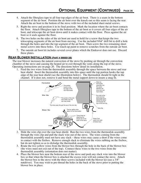
1. Feed the two wires from the thermodisk assembly through the space between the stove and rear<br />
heat shield. Insert the thermodisk assembly into this space until the top portion hooks the top<br />
edge of the rear heat shield (see the illustration below). The thermodisk should fit tight in the<br />
channel. If it does not, remove it and bend the metal support down to insure a snug fit.<br />
Thermodisk<br />
Wire Clip<br />
Blower Box<br />
FRONT<br />
This portion<br />
hooks on the<br />
top edge of the<br />
rear heat shield.<br />
This portion of the wire<br />
clips slides over the<br />
rear heat shield<br />
The wires pass through the eye of the wire clip.<br />
The two yellow wires<br />
attach to the thermodisk.<br />
Three holes for<br />
attaching the<br />
blower box to the<br />
back of the stove<br />
Slide the<br />
thermodisk<br />
assembly into<br />
the space<br />
between the<br />
stove and rear<br />
heat shield.<br />
Run both of the<br />
wires from the<br />
thermodisk down<br />
behind the stove<br />
and through the<br />
eye of the wire clip.<br />
Wire Clip<br />
Power Cord<br />
(exits from back<br />
of blower box)<br />
2. Slide the wire clip over the rear heat shield. Run the two wires from the thermodisk assembly<br />
through the wire clip and pull the slack wire out of the stove. The wires coming from the<br />
thermodisk assembly must not have any slack Ð these wires may cause a short if the wires come<br />
in contact with the firebox. Remove enough slack to eliminate the wires rubbing on the firebox,<br />
but do not tighten so as to dislodge the thermodisk assembly.<br />
3. Route the two yellow wires from the blower box through the hole in the back of the blower box<br />
(the wires must not exit out of the top). Connect these wires to the two wires from the<br />
thermodisk assembly (orientation does not matter).<br />
4. Place the blower box near the bottom rear of the stove and push any slack wire into the blower<br />
box so that when the blower box is attached the excess wire will not contact the stove. Attach<br />
the blower box to the stove with the three screws included with the blower kit (use a 3/8"<br />
nutdriver). You may wish to pre-thread the holes in the back of the stove prior to putting the<br />
blower box in place.