Revere Fireplace Insert Owner's Manual - Lopi
Revere Fireplace Insert Owner's Manual - Lopi
Revere Fireplace Insert Owner's Manual - Lopi

Create successful ePaper yourself
Turn your PDF publications into a flip-book with our unique Google optimized e-Paper software.
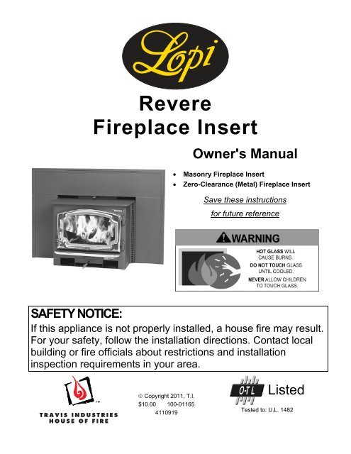
<strong>Revere</strong><br />
<strong>Fireplace</strong> <strong>Insert</strong><br />
<strong>Owner's</strong> <strong>Manual</strong><br />
Masonry <strong>Fireplace</strong> <strong>Insert</strong><br />
Zero-Clearance (Metal) <strong>Fireplace</strong> <strong>Insert</strong><br />
Save these instructions<br />
for future reference<br />
SAFETY NOTICE:<br />
If this appliance is not properly installed, a house fire may result.<br />
For your safety, follow the installation directions. Contact local<br />
building or fire officials about restrictions and installation<br />
inspection requirements in your area.<br />
Copyright 2011, T.I.<br />
$10.00 100-01165<br />
4110919<br />
Listed<br />
Tested to: U.L. 1482
2 Introduction<br />
Introduction<br />
We welcome you as a new owner of a <strong>Lopi</strong> <strong>Revere</strong> wood-burning insert. In purchasing a <strong>Lopi</strong> <strong>Revere</strong><br />
you have joined the growing ranks of concerned individuals whose selection of an energy system reflects<br />
both a concern for the environment and aesthetics. The <strong>Lopi</strong> <strong>Revere</strong> is one of the finest appliances the<br />
world over. This manual will explain the installation, operation, and maintenance of this appliance.<br />
Please familiarize yourself with the <strong>Owner's</strong> <strong>Manual</strong> before operating your appliance and save the manual<br />
for future reference. Included are helpful hints and suggestions which will make the installation and<br />
operation of your new appliance an easier and more enjoyable experience. We offer our continual<br />
support and guidance to help you achieve the maximum benefit and enjoyment from your appliance.<br />
Important Information<br />
No other <strong>Lopi</strong> <strong>Revere</strong> appliance has the same serial<br />
number as yours. The serial number is stamped onto<br />
the label on the back of the appliance.<br />
This serial number will be needed in case you require<br />
service of any type.<br />
Model: <strong>Lopi</strong> <strong>Revere</strong> ND<br />
Serial Number:<br />
Purchase Date:<br />
Purchased From:<br />
Mail your Warranty Card Today, and Save Your Bill<br />
of Sale.<br />
To receive full warranty coverage, you will need to<br />
show evidence of the date you purchased your<br />
appliance. Do not mail your Bill of Sale to us.<br />
We suggest that you attach your Bill of Sale to this<br />
page so that you will have all the information you need<br />
in one place should the need for service or information<br />
occur.<br />
© Travis Industries 100-01165 4110919
Introduction ...................................................... 2<br />
Important Information ...................................... 2<br />
Installation Options .......................................... 6<br />
Features ............................................................ 6<br />
Heating Specifications ..................................... 6<br />
Dimensions ....................................................... 6<br />
Emissions ......................................................... 6<br />
Planning the Installation .................................. 7<br />
Preparation for Installation .................................... 7<br />
Additional Accessories Needed for Installation ..... 7<br />
Installation Considerations .................................... 7<br />
<strong>Fireplace</strong> Requirements .................................. 8<br />
<strong>Fireplace</strong> Altered Tag ....................................... 8<br />
<strong>Insert</strong> Placement Requirements ..................... 9<br />
Masonry <strong>Fireplace</strong> Requirements .................. 9<br />
Zero-Clearance (Metal) <strong>Fireplace</strong><br />
Requirements ................................................... 9<br />
Hearth Requirements ..................................... 10<br />
Drafting Performance .................................... 10<br />
<strong>Insert</strong> Rollers .................................................. 10<br />
Leveling Bolt Installation ............................... 10<br />
Block-Off Plate Installation ........................... 11<br />
<strong>Insert</strong> with Positive Connection ........................... 12<br />
<strong>Insert</strong> with Direct Connection (Masonry <strong>Fireplace</strong>)12<br />
<strong>Insert</strong> with Direct Connection (Z.C. <strong>Fireplace</strong>) .... 13<br />
Safety Notice .................................................. 14<br />
Before Your First Fire .................................... 14<br />
Verify the Installation ........................................... 14<br />
Curing the Paint .................................................. 14<br />
Over-Firing the <strong>Insert</strong> .......................................... 14<br />
Opening the Door ........................................... 14<br />
Bypass Operation .......................................... 15<br />
Starting a Fire ................................................. 16<br />
Adjusting the Burn Rate ................................ 17<br />
Approximate Air Control Settings ........................ 17<br />
Ash Removal .................................................. 17<br />
Table of Contents 3<br />
Optional Blower Operation ........................... 18<br />
Re-Loading the <strong>Insert</strong> .................................... 18<br />
Overnight Burn ............................................... 18<br />
Normal Operating Sounds ............................ 18<br />
Hints for Burning ........................................... 19<br />
Selecting Wood .............................................. 19<br />
Why Dry Wood is Key ......................................... 19<br />
Wood Cutting and Storage .................................. 19<br />
Troubleshooting ............................................. 20<br />
Daily Maintenance (while <strong>Insert</strong> is in use) ... 21<br />
Remove Ash (if necessary) ................................. 21<br />
Clean the Glass (if necessary) ............................ 21<br />
Monthly Maintenance (while appliance is in<br />
use) .................................................................. 22<br />
Door and Glass Inspection .................................. 22<br />
Creosote - Formation and Need for Removal ..... 22<br />
Yearly Maintenance ....................................... 23<br />
Touch-Up Paint ................................................... 23<br />
Cleaning the Air Duct and Blower (if applicable) . 23<br />
Firebrick and Baffle Inspection ............................ 23<br />
Door Parts ....................................................... 24<br />
Replacing the Glass ............................................ 24<br />
Replacing the Door Gasket ................................. 24<br />
Replacing the Door Handle ................................. 24<br />
Firebox Parts .................................................. 25<br />
Floor and Side Firebrick Removal & Replacement25<br />
Baffle Removal & Replacement .................... 26<br />
Air Tube Removal & Replacement ............... 26<br />
Listing Label ........................................................ 28<br />
Door Shell Installation ................................... 29<br />
Surround Panels ............................................ 32<br />
Rectangular Panels ............................................. 32<br />
Arched Panels (Part # 99300109) ....................... 32<br />
Installation Instructions ....................................... 32<br />
Front Blower (part # 99000128) .................... 34<br />
Switching the Power Cord to the Left Side .......... 34<br />
Front Blower Installation Instructions .................. 34<br />
© Travis Industries 100-01165 4110919
4 Safety Precautions<br />
The viewing door must be<br />
closed and latched during<br />
operation.<br />
Smoke from this appliance may<br />
active a smoke detector when<br />
the door is open.<br />
Never block free airflow through<br />
the air vents on this appliance.<br />
This appliance is designed and<br />
approved for the burning of cord<br />
wood only. Do not attempt to<br />
burn any other type of fuel other<br />
than cord wood in this<br />
appliance, it will void all<br />
warranties and safety listings.<br />
Do not touch the appliance while<br />
it is hot and educate all children<br />
of the danger of a hightemperature<br />
appliance. Young<br />
children should be supervised<br />
when they are in the same room<br />
as the appliance.<br />
This appliance must be properly<br />
installed to prevent the<br />
possibility of a house fire. The<br />
instructions must be strictly<br />
adhered to. Do not use<br />
makeshift methods or<br />
compromise in the installation.<br />
Inspect the chimney connector<br />
and chimney at least twice<br />
monthly and clean if necessary.<br />
Creosote may build up and<br />
cause a house fire.<br />
Do not connect this appliance to<br />
any chimney serving another<br />
appliance.<br />
Gasoline or other flammable<br />
liquids must never be used to<br />
start the fire or "Freshen Up" the<br />
fire. Do not store or use<br />
gasoline or other flammable<br />
liquids in the vicinity of this<br />
appliance.<br />
Ashes must be disposed in a<br />
metal container with a tight lid<br />
and placed on a noncombustible<br />
surface well away<br />
from the home or structure.<br />
Keep furniture, drapes, curtains,<br />
wood, paper, and other<br />
combustibles a minimum of 36"<br />
away from the front of the<br />
appliance.<br />
Contact your local building<br />
officials to obtain a permit and<br />
information on any installation<br />
restrictions or inspection<br />
requirements in your area.<br />
Notify your insurance company<br />
of this appliance as well.<br />
This appliance must be<br />
connected to a listed high<br />
temperature (UL 103 HT)<br />
residential type chimney or an<br />
approved masonry chimney with<br />
a standard clay tile, or stainless<br />
steel liner.<br />
© Travis Industries 100-01165 4110919<br />
36"<br />
Gas<br />
ASHES<br />
Type<br />
HT<br />
Ok<br />
Clay<br />
Liner
This<br />
<strong>Manual</strong><br />
Mobile<br />
Home<br />
<br />
<br />
<br />
Safety Precautions 5<br />
When installed in a mobile<br />
home, this appliance must be<br />
bolted to the floor, have outside<br />
air, and not be installed in the<br />
bedroom (Per H.U.D.<br />
requirements). Check with local<br />
building officials.<br />
Never try to repair or replace<br />
any part of this appliance unless<br />
instructions are given in this<br />
manual. All other work must be<br />
done by a trained technician.<br />
Allow the appliance to cool<br />
before carrying out any<br />
maintenance or cleaning.<br />
Maintain the door and glass seal<br />
and keep them in good<br />
condition.<br />
Do not operate this heater with<br />
broken or missing glass.<br />
Avoid placing wood against the<br />
glass when loading. Do not<br />
slam the door or strike the glass.<br />
Do not throw this manual away.<br />
This manual has important<br />
operating and maintenance<br />
instructions that you will need at<br />
a later time. Always follow the<br />
instructions in this manual.<br />
Do not place clothing or other<br />
flammable items on or near this<br />
appliance.<br />
Do not make any changes or<br />
modifications to an existing<br />
masonry fireplace or chimney to<br />
install this appliance.<br />
Do not make any changes to the<br />
appliance to increase<br />
combustion air.<br />
Over-firing the appliance may<br />
cause a house fire. If a unit or<br />
chimney connector glows, you<br />
are over-firing.<br />
Do not use a grate or other<br />
device to elevate the fire off of<br />
the firebox floor. Burn the fire<br />
directly on the bricks.<br />
Travis Industries, Inc. grants<br />
no warranty, implied or<br />
stated, for the installation or<br />
maintenance of your<br />
appliance, and assumes no<br />
responsibility of any<br />
consequential damage(s).<br />
© Travis Industries 100-01165 4110919
6 Features & Specifications<br />
Installation Options<br />
Masonry <strong>Fireplace</strong> <strong>Insert</strong><br />
Zero-Clearance (Metal) <strong>Fireplace</strong> <strong>Insert</strong><br />
Heating Specifications<br />
Features<br />
EPA Phase II Approved<br />
2.2 Cubic Foot Firebox Volume<br />
Single Operating Control<br />
Accepts Logs Up to 18" Long<br />
Steel Plate Construction (5/16" & 3/16")<br />
Heavy Duty Refractory Firebrick<br />
Optional High-Tech Blower<br />
Approximate Maximum Heating Capacity (in square feet)* 1,200 to 2,000<br />
Maximum BTUs per Hour (Cord Wood Calculation) 72,400<br />
Overall Efficiency (Oregon Method) 70.4 %<br />
Maximum Burn Time Up to 10 Hours<br />
* Heating capacity will vary depending on the home's floor plan, degree of insulation, and the outside<br />
temperature. It is also affected by the quality and moisture level of the fuel.<br />
Dimensions<br />
a Measure side<br />
and top<br />
clearances from<br />
the top plate.<br />
b Measure front<br />
clearances from<br />
the stove face.<br />
Emissions<br />
Weight....380 Lbs. 170 Kg.<br />
b<br />
a<br />
24-1/4"<br />
616mm<br />
21-3/8"<br />
543mm<br />
Figure 1<br />
5-3/16" 132mm<br />
18-3/4"<br />
477mm<br />
1.9 Grams per Hour (EPA Phase II Approved) – Tests conducted by E.E.S.P.C.<br />
21-5/8" 550mm<br />
13-1/8" 334mm<br />
ZC (metal) fireplaces require 1"<br />
26mm clearance to the rear.<br />
© Travis Industries 100-01165 4110919<br />
<strong>Fireplace</strong> Opening<br />
19-3/4"<br />
502mm<br />
10" 254mm (does not include<br />
required hearth)
Stove Installation (for qualified installers only) 7<br />
SAFETY NOTICE:<br />
Please read this entire manual before you install and use your new room heater. Failure to<br />
follow instructions may result in property damage, bodily injury, or even death. Contact<br />
local building or fire officials about restrictions and installation inspection requirements in<br />
your area.<br />
Planning the Installation<br />
We suggest that you have an authorized Travis Industries dealer install your <strong>Insert</strong>. If you install the<br />
<strong>Insert</strong> yourself, your authorized dealer should review your installation plans.<br />
Check with local building officials for any permits required for installation of this <strong>Insert</strong> and notify your<br />
insurance company before proceeding with installation.<br />
Preparation for Installation<br />
Check for damage to the exterior of the <strong>Insert</strong> (dents should be reported, scratches can be fixed by<br />
applying touch-up paint).<br />
Check the interior of the firebox (replace cracked firebrick and make sure baffle is in place).<br />
The insert can be lightened by removing the firebricks and baffle (pg. 25) - replace before operation.<br />
Additional Accessories Needed for Installation<br />
Door Shell (Black 99300195 Brass 99300196 or Pewter<br />
Surround Panels<br />
Installation Considerations<br />
Installation Type<br />
<strong>Insert</strong> with Positive Flue (Full Reline)<br />
<strong>Insert</strong> with Direct Connect Flue<br />
Considerations<br />
• Utilizes existing masonry or zero clearance fireplace<br />
• Provides best draft<br />
• Easiest to clean<br />
• Utilizes existing masonry or zero clearance fireplace<br />
• Provides good draft<br />
• Requires fireplace block-off plate - see page 11<br />
© Travis Industries 100-01165 4110919
8 Stove Installation (for qualified installers only)<br />
<strong>Fireplace</strong> Requirements<br />
j<br />
The diagram below shows the minimum size requirements for the type of fireplace used.<br />
i<br />
Combustible Mantel<br />
Non-Combustible Facing<br />
<strong>Fireplace</strong> Altered Tag<br />
a<br />
b<br />
h<br />
c e<br />
Non-Combustible Hearth<br />
g<br />
d<br />
f<br />
Figure 2<br />
Minimum <strong>Fireplace</strong><br />
Size<br />
Masonry<br />
<strong>Fireplace</strong><br />
a Height (front) 19.75"<br />
502mm<br />
b Height (rear) 19.75"<br />
362mm<br />
c Width (front) 24.25"<br />
616mm<br />
d Width (rear) 21-5/8"<br />
551mm<br />
e Depth 13-1/8"<br />
334mm<br />
f Hearth Depth* 26" 661mm (US)<br />
- - - - - - - - - - - - - -<br />
28” 712mm (CAN)<br />
g Hearth Width 40.25"<br />
1023mm<br />
h Facing Width 50.25"<br />
1277mm<br />
i Facing Height<br />
with mantel shield<br />
j Mantel Height<br />
with mantel shield<br />
47.25" 1201mm<br />
39.25” 997mm<br />
49.25" 902mm<br />
41.25 1048mm<br />
Z.C. (Metal)<br />
<strong>Fireplace</strong><br />
19.75"<br />
502mm<br />
19.75"<br />
502mm<br />
26.25"<br />
667mm<br />
23.625"<br />
602mm<br />
14.125"<br />
359mm<br />
26" 661mm (US)<br />
- - - - - - - - - - - - - -<br />
28” 712mm (CAN)<br />
40.25"<br />
1023mm<br />
48.25"<br />
1226mm<br />
Attach the "This fireplace has been altered..." plate to the fireplace (use two screws or other suitable<br />
method). You may wish to place it in a location where it will be covered by the surround panels.<br />
30.75" 782mm<br />
N/A<br />
42.75" 1086mm<br />
N/A<br />
© Travis Industries 100-01165 4110919
Stove Installation (for qualified installers only) 9<br />
<strong>Insert</strong> Placement Requirements<br />
The insert must be placed so that no combustibles are within, or can swing within (e.g. drapes, doors), 36" of the<br />
front of the insert.<br />
<strong>Insert</strong> and hearth must be installed on a level, secure floor.<br />
The minimum clearances, facing, and hearth requirements must be met (follow the clearances for the type of<br />
fireplace being used - either masonry or zero-clearance).<br />
Side<br />
Wall<br />
<br />
<br />
<br />
<br />
n<br />
<br />
<br />
<br />
m<br />
<br />
<br />
<br />
k <br />
<br />
<br />
l<br />
<br />
<br />
<br />
p<br />
<br />
<br />
<br />
<br />
<br />
q x<br />
<br />
<br />
<br />
o<br />
<br />
<br />
<br />
<br />
Non-Combustible<br />
Hearth<br />
Combustible Mantel<br />
Combustible Top Facing<br />
Masonry <strong>Fireplace</strong> Requirements<br />
Minimum Clearances Masonry<br />
<strong>Fireplace</strong><br />
Z.C. (Metal)<br />
<strong>Fireplace</strong><br />
k Sidewall to <strong>Insert</strong> 15" 381mm 30" 762mm<br />
l Side Facing 13" 331mm 12" 305mm<br />
m Top Facing<br />
with mantel shield<br />
n Mantel to <strong>Insert</strong><br />
with mantel shield<br />
28.5" 724mm<br />
20.5” 521mm<br />
30.5" 775mm<br />
22.5” 572mm<br />
o Front Hearth 16" 407mm (US)<br />
- - - - - - - - - - - -<br />
18” 458mm<br />
(Canada)<br />
12" 305mm<br />
N/A<br />
24" 610mm<br />
N/A<br />
16" 407mm (US)<br />
- - - - - - - - - -<br />
18” 458mm<br />
(Canada)<br />
p Side Hearth 8" 203mm 8" 203mm<br />
q Front of <strong>Insert</strong> 36" 915mm 36" 915mm<br />
x Extension Onto<br />
Hearth<br />
10"<br />
77mm<br />
10"<br />
77mm<br />
Chimney must have a clay tile liner or a stainless steel liner (positive connection).<br />
Entire fireplace, including chimney, must be clean and undamaged. Any damage must be repaired prior to<br />
installation of the insert.<br />
Chimney height: 15' minimum; 33' maximum.<br />
Entire fireplace, including chimney, must meet local building requirements.<br />
Zero-Clearance (Metal) <strong>Fireplace</strong> Requirements<br />
Facing<br />
Must utilize a positive (full reline) or direct connection (block-off plate)<br />
Must be manufactured by one of the following manufacturers:<br />
• Marco • Majestic • Heatilator • Preway • Tempco • Superior<br />
• Heat N Glo • Lennox • Martin • Monesson<br />
Entire fireplace, including chimney, must be clean and undamaged. Any damage must be repaired prior to<br />
installation of the insert<br />
Entire fireplace, including chimney, must meet local building requirements<br />
Chimney height: 15' minimum; 33' maximum.<br />
Minimum cross section: 28.65 square inches<br />
H<br />
The damper ("A") and grate ("B") must be removed.<br />
The smoke shelf ("C"), internal baffles ("D"), screen<br />
F<br />
C<br />
A<br />
("E"), and metal or glass doors ("F") may be<br />
D<br />
removed (if applicable). The masonry lining ("G"),<br />
insulation ("H"), and any structured rigid frame<br />
E<br />
I<br />
members (metal sides, floor, door frame, face of the<br />
fireplace, etc. – "I") may not be removed or altered<br />
B<br />
G<br />
Figure 3<br />
Figure 4<br />
© Travis Industries 100-01165 4110919
10 Stove Installation (for qualified installers only)<br />
Hearth Requirements<br />
Must extend in front of the insert and on both sides (see <strong>Insert</strong> Placement Requirements for details)<br />
Must be non-combustible and at least .018" thick (26 gauge)<br />
Drafting Performance<br />
This appliance relies upon natural draft to operate. External forces, such as wind, barometric pressure, topography,<br />
or factors of the home (negative pressure from exhaust fans, chimneys, air infiltration, etc.), may adversely affect<br />
draft. Travis Industries cannot be responsible for external forces leading to less than optimal performance.<br />
<strong>Insert</strong> Rollers<br />
Two rollers are built into the back edge of the insert. This<br />
allows the insert to be rolled into position by lifting the front<br />
of the insert and pushing it into position (see Figure 5).<br />
Leveling Bolt Installation<br />
Two leveling bolts are pre-installed on the insert to allow<br />
for proper leveling within the fireplace. To access the<br />
bolts, remove the back corner firebricks and cover plates<br />
(see Figure 6 “a” and “b”). The bolts are pre-threaded to a<br />
weld-nut on the base of the insert. Use a 3/4” socket<br />
wrench to screw the bolts down (clockwise) until the insert<br />
is level (see “c”).<br />
MASONRY NOTE: You may wish to place a metal plate<br />
below the bolt if the masonry is weak.<br />
SEALING THE COVER PLATE: We recommend sealing<br />
the cover plate with furnace cement (place on underside of<br />
cover plate).<br />
BOLT LENGTH: The included bolts allow approximately 1”<br />
of rise. If additional rise is required, use a longer 1/2-13<br />
thread bolt. Make sure the additional bolt length does not<br />
interfere with the cover plate.<br />
Figure 5<br />
Figure 6<br />
© Travis Industries 100-01165 4110919<br />
a<br />
b<br />
c 3/4"
Block-Off Plate Installation<br />
Stove Installation (for qualified installers only) 11<br />
Whenever this appliance is installed with a direct connection a block-off plate, or other non-combustible<br />
seal-off device (e.g. damper adapter), will need to be installed. This device is used to seal the chimney,<br />
insuring no smoke enters the home and providing the chimney system with a seal to promote draft. The<br />
directions below detail the steps for construction and installation of a block-off plate.<br />
Determine a location for the block-off plate at the top of the firebox below the damper area (make<br />
it high enough to allow installation of the connection pipe). The location should be level and in an<br />
area where it can be mounted easily. Measure the width at the rear ("A") and front ("B") of the<br />
firebox at the height where the block-off plate will be installed (see Figure 7). Then measure the<br />
depth of the location where the block-off plate will be installed ("C").<br />
NOTE: Most masonry fireplaces have square fireboxes while certain zero-clearance (metal)<br />
fireplaces often have domed firebox tops. This makes zero-clearance block-off plates more<br />
difficult to install. To simplify the procedure, insulation may be used to seal the rounded edges.<br />
Make a cardboard template of the measurements, but add a 2" flange to each side. This flange<br />
will be used to mount the block-off plate to the inside of the firebox. Bend the flanges downwards<br />
on the template and place it inside the fireplace. If the template fits correctly in its planned<br />
location, go to the next step. If it does not, make a new template with the appropriate corrections<br />
until it fits correctly.<br />
With the template in place, mark the location of the flue (see “Dimensions”). This location<br />
approximates the center of the flue when the insert is in place (a slight offset may occur based<br />
upon insert and block-off plate placement). Remove the template and cut a 6 1/4" diameter hole<br />
centered on this mark.<br />
Make the block-off plate of 24 gauge or thicker steel to match the template. Drill two holes in<br />
each flange for mounting the plate.<br />
Mount the block-off plate using masonry screws.<br />
NOTE: Use sheet metal screws on zero-clearance (metal) fireplaces (screws need only be long<br />
enough to penetrate the first layer of metal).<br />
Insulate the block-off plate using high-temperature fiberglass insulation (Kaowool® or equivalent)<br />
and furnace cement (allow the cement to dry for at least 24 hours before burning).<br />
After placing the appliance and installing the pipe through the block-off plate, use hightemperature<br />
fiberglass insulation and furnace cement to seal any cracks between the pipe and<br />
block-off plate.<br />
See the<br />
dimensions to<br />
determine the<br />
location of the<br />
center of the<br />
flue.<br />
B<br />
<br />
<br />
Damper<br />
<br />
<br />
<br />
<br />
C<br />
A<br />
<br />
<br />
<br />
Firebox<br />
Block-Off Plate Template<br />
2" Flanges<br />
(for attaching<br />
the block-off<br />
plate)<br />
Measurement<br />
"A"<br />
Measurement "B"<br />
See the dimensions to determine the location of<br />
the center of the flue.<br />
Measurement<br />
"C"<br />
Figure 7<br />
© Travis Industries 100-01165 4110919
12 Stove Installation (for qualified installers only)<br />
<strong>Insert</strong> with<br />
Positive<br />
Connection<br />
NOTE:<br />
Most factory-built<br />
chimney manufacturers<br />
make stainless steel<br />
chimney liners, either<br />
flexible or rigid. This<br />
provides a wide variety<br />
of installation options.<br />
Make sure to follow the<br />
manufacturer's<br />
instructions for<br />
installation and support.<br />
REQUIRED IN<br />
CANADA<br />
<strong>Insert</strong> with Direct<br />
Connection<br />
(Masonry <strong>Fireplace</strong>)<br />
NOTE:<br />
Direct connections require<br />
installation of an airtight<br />
block-off plate or damper<br />
adapter (see "Block-off<br />
Plate Installation" on page<br />
11).<br />
NOT ALLOWED IN<br />
CANADA<br />
NOTE: This installation may be<br />
used with a masonry or zero<br />
clearance fireplace. The<br />
requirements in the section<br />
"Masonry <strong>Fireplace</strong> Requirements"<br />
or "Zero Clearance Fireplaace<br />
Requirements" must be fulfilled<br />
prior to installation.<br />
Combustible Mantle<br />
Surround Panels<br />
Install a non-combustible<br />
cover plate to prevent water<br />
from entering the chimney<br />
See the section "<strong>Insert</strong><br />
Placement Requirements" for<br />
minimum clearances and<br />
hearth required.<br />
<br />
NOTE: This installation may be<br />
used with a masonry or zero<br />
clearance fireplace. This<br />
illustration depicts a masonry<br />
insert, all requirements in the<br />
section "Masonry <strong>Fireplace</strong><br />
Requirements" must be fulfilled<br />
prior to installation.<br />
Combustible Mantle<br />
Surround Panels<br />
See the section<br />
"<strong>Insert</strong> Placement<br />
Requirements" for<br />
minimum clearances<br />
and hearth required.<br />
<br />
<br />
<br />
<br />
<br />
<br />
<br />
<br />
<br />
<br />
<br />
<br />
<br />
<br />
<br />
<br />
<br />
<br />
<br />
<br />
<br />
<br />
<br />
<br />
<br />
Cap (prevents water<br />
from entering)<br />
Flue Liner<br />
The liner must be<br />
stainless steel<br />
connector or flexible<br />
vent. Follow the liner<br />
manufacturer's<br />
insturctions for<br />
installation and<br />
support.<br />
Airtight Insulated<br />
Clean-Out<br />
Remove damper<br />
or wire it open<br />
Airtight<br />
Insulated<br />
Clean-Out<br />
Remove<br />
damper<br />
or wire it<br />
open<br />
Block-off plate or<br />
damper adapter<br />
Figure 8<br />
Stainless steel<br />
chimney connector<br />
must Extend 1' past<br />
the block-off plate or<br />
to the flue liner<br />
Figure 9<br />
© Travis Industries 100-01165 4110919<br />
Flue<br />
Liner
<strong>Insert</strong> with Direct<br />
Connection (Z.C.<br />
<strong>Fireplace</strong>)<br />
NOTE:<br />
Direct connections require<br />
installation of an airtight<br />
block-off plate or damper<br />
adapter (see "Block-off<br />
Plate Installation" on page<br />
11).<br />
NOT ALLOWED IN<br />
CANADA<br />
Stove Installation (for qualified installers only) 13<br />
NOTE: This installation may be<br />
used with a masonry or zero<br />
clearance fireplace. This<br />
illustration depicts a zero<br />
clearance insert, all requirements<br />
in the section "Zero Clearance<br />
<strong>Fireplace</strong> Requirements" must be<br />
fulfilled prior to installation.<br />
Combustible Mantle<br />
Surround Panels<br />
See the section<br />
"<strong>Insert</strong> Placement<br />
Requirements" for<br />
minimum clearances<br />
and hearth required.<br />
Optional<br />
Telescoping Legs<br />
<br />
<br />
<br />
<br />
Stainless steel<br />
chimney connector<br />
must Extend 1' past<br />
the block-off plate.<br />
Damper must<br />
be removed<br />
Block-off plate or<br />
damper adapter<br />
Z.C. (Metal) firebox<br />
No modification to the firebox<br />
of the z.c. fireplace is allowed.<br />
Figure 10<br />
© Travis Industries 100-01165 4110919
14 Operating Your Appliance<br />
Safety Notice<br />
If this appliance is not properly installed, a house fire may result. For your safety, follow the installation<br />
directions. Contact local building or fire officials about restrictions and installation inspection<br />
requirements in your area.<br />
Read and follow all of the warnings on pages 4 and 5 of this manual.<br />
Before Your First Fire<br />
Verify the Installation<br />
Before starting the <strong>Insert</strong>, verify that the <strong>Insert</strong> is properly installed and all of the requirements in this<br />
manual have been followed.<br />
Keep all flammable materials 36" away from the front of the <strong>Insert</strong> (drapes, furniture, clothing, etc.).<br />
Curing the Paint<br />
This heater uses a heat-activated paint that will emit some fumes while<br />
starting the first fire. Open doors and windows to the room to vent these<br />
fumes. This typically lasts two to four hours. You may also notice oil burning<br />
off of the interior of the heater. This rust-stopping agent will soon dissipate.<br />
Door Gasket - The door gasket might adhere to the paint on the front of the<br />
heater. Leave the door slightly ajar for the first fire and be careful when<br />
opening the door after the first fire.<br />
Over-Firing the <strong>Insert</strong><br />
This <strong>Insert</strong> was designed to operate at a high temperature. But due to differences in vent configuration,<br />
fuel, and draft, this appliance can be operated at an excessive temperature. If the <strong>Insert</strong> top or other area<br />
starts to glow red, you are over-firing the <strong>Insert</strong>. Shut the air control down to low and allow the <strong>Insert</strong> to<br />
cool before proceeding.<br />
Over-firing may lead to damage of plated surfaces. If you are uncertain of over-firing conditions, we<br />
suggest placing an <strong>Insert</strong> thermometer (e.g. Rutland® Model 710) directly over the door on the <strong>Insert</strong> top<br />
- temperatures exceeding 800° are generally considered over-firing and will void the warranty.<br />
Opening the Door<br />
Rotate<br />
the door<br />
handle.<br />
Swing<br />
the door<br />
open.<br />
2 to 4 hours<br />
<br />
<br />
<br />
<br />
<br />
The door becomes hot during use. Use a glove to open the door if the handle is hot.<br />
To prevent smoke from entering the room, open the air control before opening the door. You can also<br />
open the door a small amount and let air enter the firebox.<br />
© Travis Industries 100-01165 4110919
Bypass Operation<br />
Operating Your Appliance 15<br />
The bypass controls the flow of smoke inside the heater. When pulled out, smoke goes directly up the<br />
flue, creating more draft. When pushed in, the smoke goes around the baffle, utilizing the secondary<br />
combustion and making the heater more efficient.<br />
When starting or re-loading, pull the bypass out.<br />
During normal operation, push the bypass in.<br />
Use the included pull tool<br />
to operate the bypass rod<br />
<br />
Bypass Pulled Out<br />
Used for starting and re-loading<br />
Bypass Pushed In<br />
Used for normal operation<br />
<br />
<br />
<br />
<br />
<br />
<br />
<br />
<br />
<br />
<br />
© Travis Industries 100-01165 4110919
16 Operating Your Appliance<br />
Starting a Fire<br />
Since the dawn of time man has debated the best way to start a fire. Some use the boy-scout "tee-pee";<br />
some prefer the "tic-tac-toe" stack. Either way, review the hints and warnings below to ensure proper fire<br />
starting.<br />
Make sure the air control is pushed in. If additional air is needed, open the doors 1/4" during the first<br />
five minutes of start-up.<br />
<br />
Never use gasoline, gasoline-type lantern fuel, kerosene, charcoal lighter fluid, or similar liquids to start<br />
or "freshen up" a fire in this <strong>Insert</strong>. Keep all such liquids well away from the <strong>Insert</strong> while it is in use.<br />
DO NOT USE CHEMICALS OR FLUIDS TO START THE FIRE. DO NOT BURN GARBAGE OR<br />
FLAMMABLE FLUIDS SUCH AS GASOLINE, NAPHTHA OR ENGINE OIL. Do not place such fuel<br />
within space heater installation clearances or within the space required for charging and ash removal.<br />
If using a fire-starter, use only products specifically designed for <strong>Insert</strong>s - follow the manufacturer's<br />
instructions carefully.<br />
HOT WHILE IN OPERATION. KEEP CHILDREN, CLOTHING AND FURNITURE AWAY. CONTACT<br />
MAY CAUSE SKIN BURNS.<br />
If the smoke does not pass up the chimney, ball up one sheet of newspaper, place it in the center of the<br />
firebox and light it. This should start the chimney drafting (this eliminates "cold air blockage").<br />
Use plenty of kindling to ensure the <strong>Insert</strong> reaches a proper temperature. Once the kindling is burning<br />
rapidly, place a few larger pieces of wood onto the fire.<br />
© Travis Industries 100-01165 4110919
Adjusting the Burn Rate<br />
Operating Your Appliance 17<br />
Use the air control slider to control the burn rate of the insert. See the illustration below for details.<br />
Low Burn<br />
(air control closed)<br />
<br />
<br />
Approximate Air Control Settings<br />
Ash Removal<br />
ASHES<br />
Use the air control to<br />
change the burn rate.<br />
<br />
<br />
High Burn<br />
(air control open)<br />
<br />
<br />
Overnight Burn Fully in to 1/8" open<br />
Medium Burn 1/8" to 5/8" open<br />
Medium High Burn 5/8" to fully open<br />
High Burn Fully open (pulled out)<br />
The air control becomes hot during operation - use gloves or a tool to prevent burns.<br />
The air control may take several minutes to influence the burn rate. When making adjustments, you<br />
may wish to let the <strong>Insert</strong> burn for 10 minutes to gauge performance.<br />
Ashes should be placed in a metal container with a tight fitting lid. The closed container of ashes<br />
should be placed on a noncombustible floor or on the ground, away from all combustible<br />
materials, pending final disposal. If the ashes are disposed of by burial in soil or otherwise locally<br />
dispersed, they should be retained in the closed container until all cinders have thoroughly<br />
cooled.<br />
© Travis Industries 100-01165 4110919
18 Operating Your Appliance<br />
Optional Blower Operation<br />
The blower will turn on once the <strong>Insert</strong> is up to temperature. This is typically 15 to 30 minutes after<br />
starting the fire. Follow the directions below to alter the blower speed.<br />
OFF<br />
Turn the dial all the way counterclockwise<br />
until it clicks off.<br />
BLOWER<br />
CONTROL <br />
LO<br />
<br />
The blower may be used to affect heat output (i.e.: to reduce heat output, turn the blower down).<br />
Route the power cord in a location where it will not come in contact with the appliance or become hot.<br />
Re-Loading the <strong>Insert</strong><br />
Follow the directions below to minimize smoke spillage while re-loading the insert.<br />
1 Open the air control all the way (pull it out). Open the bypass (pull it out).<br />
2 Open the door slightly. Let the airflow inside the firebox to stabilize before opening the doors fully.<br />
3 Load wood onto the fire.<br />
Overnight Burn<br />
OFF <br />
HI<br />
<br />
<br />
<br />
This insert is large enough to accommodate burn times up to eight hours. Follow the steps below to<br />
achieve an overnight burn.<br />
1 Move the air control to high burn and let the insert become hot (burn for approximately 15 minutes).<br />
2 Load as much wood as possible. Use large pieces if possible.<br />
3 Let the insert burn on high for 15 minutes to keep the insert hot, and then turn the air control to low.<br />
4 In the morning the insert should still be hot, with embers in the coal bed. Stir the coals and load<br />
small pieces of wood to re-ignite the fire, if desired.<br />
Differences if chimney height and draft may lower overall burn times.<br />
Normal Operating Sounds<br />
© Travis Industries 100-01165 4110919<br />
HIGH<br />
The high position is all the way counterclockwise,<br />
without clicking off.<br />
<br />
OFF <br />
HI<br />
LO <br />
<br />
<br />
BLOWER<br />
CONTROL<br />
Creaks and Clicks:<br />
The 3/16" and 5/16" steel may creak or click when<br />
the stove heats up and cools down - this is normal.<br />
Blower Sounds:<br />
The blower will make a slight "humm" as it<br />
pushes air through the stove.<br />
Hint:<br />
Make sure the leveling bolts on legs are extended -<br />
preventing the hearth from amplifying any vibrations.<br />
<br />
LOW<br />
Turn the dial all the<br />
way clockwise.<br />
<br />
OFF <br />
HI<br />
LO <br />
<br />
<br />
BLOWER<br />
CONTROL
Hints for Burning<br />
Operating Your Appliance 19<br />
Get the appliance hot before adjusting to low burn<br />
Use smaller pieces of wood during start-up and high burns to increase temperature<br />
Use larger pieces of wood for overnight or sustained burns<br />
Stack the wood tightly together to establish a longer burn<br />
Leave a bed of ashes (1/2" deep) to allow for longer burns<br />
Be considerate of neighbors & the environment: burn dry wood only<br />
Burn small, intense fires instead of large, slow burning fires when possible<br />
Learn your appliance's operating characteristics to obtain optimum performance<br />
Selecting Wood<br />
Dry Wood is Key<br />
Dry wood burns hot, emits less<br />
smoke and creates less creosote.<br />
Testing Wood Moisture<br />
Split wood stored in a dry area will<br />
be fully dry within a year. This<br />
insures dry wood. If purchasing<br />
wood for immediate use, test the<br />
wood with a moisture meter. Some<br />
experienced wood burners can<br />
measure wood moisture by<br />
knocking pieces together and<br />
listening for a clear "knock" and not<br />
a "thud".<br />
Why Dry Wood is Key<br />
Wet wood, when burned, must release water stored within the wood. This cools the fire, creates<br />
creosote, and hampers a complete burn. Ask any experienced wood burner and he or she will agree: dry<br />
wood is crucial to good performance.<br />
Wood Cutting and Storage<br />
Cut wood to length and<br />
chop into quarters.<br />
Wet<br />
Wood<br />
© Travis Industries 100-01165 4110919<br />
Less<br />
Heat<br />
Leads<br />
To<br />
Leads<br />
To<br />
More Smoke<br />
and Creostoe<br />
Store the wood off the ground in a<br />
covered area. Allow for airflow<br />
around the wood to dry the wood.<br />
Air Flow<br />
Dry<br />
Wood<br />
More<br />
Heat<br />
Leads<br />
To<br />
Leads<br />
To<br />
Less Smoke<br />
and Creostoe<br />
Air Flow<br />
Air Flow
20 Operating Your Appliance<br />
Troubleshooting<br />
Problem Possible Cause<br />
Smoke Enters Room During<br />
Start-Up<br />
Kindling Does Not Start - Fire<br />
Smolders<br />
Smoke Enters Room While Re-<br />
Loading<br />
Open the air control (pg. 17).<br />
Open the bypass (pg. 15).<br />
Cold Air Blockage - burn a piece of newspaper to<br />
establish a draft.<br />
If the flame is not getting enough air, a small crack in<br />
the door is all that is needed.<br />
Open the bypass (pg. 15).<br />
Open the air control (pg. 17).<br />
Not enough starter paper - use additional newspaper if<br />
necessary.<br />
If the flame is not getting enough air, a small crack in<br />
the door is all that is needed.<br />
Open the bypass (pg. 15) before opening the door.<br />
Open the air control before opening the door (pg. 17).<br />
Let the air stabilize before fully opening the door.<br />
Then open the door approximately 1 inch. Let air go<br />
into the firebox for a few seconds. Once the smoke<br />
appears to be flowing up the chimney consistently,<br />
open the door.<br />
Insufficient Draft - Chimney height and outside<br />
conditions can negatively affect draft. In these cases a<br />
small amount of smoke may enter the home. Adding<br />
more piping or a draft-inducing cap may help.<br />
<strong>Insert</strong> Does Not Burn Hot Enough Wood is Wet - see the section "Selecting Wood" on<br />
page 19 for details on wood.<br />
Make sure the air control is all the way open. Slide the<br />
control back and forth to insure the control is not stuck.<br />
Insufficient Draft - Chimney height and outside<br />
conditions can negatively affect draft. In these cases<br />
the fire may burn slowly. Adding more piping or a<br />
draft-inducing cap may help.<br />
Blower Does Not Run <strong>Insert</strong> is Not Up to Temperature - This is normal. The<br />
blower will come on when the <strong>Insert</strong> is hot - usually 15<br />
to 30 minutes.<br />
Electricity is Cut to the Blower - Check the household<br />
breaker or fuse to make sure it is operable.<br />
<strong>Insert</strong> Does Not Burn Long<br />
Enough<br />
Depending upon wood, draft, and other factors, the<br />
burn time may be shorter then stated. Make sure the<br />
doors are sealing and not allowing air into the firebox -<br />
See the section "Door and Glass Inspection" on page<br />
22 for details.<br />
Check the ash bed for coals. Often, coals are still<br />
glowing under a slight bed of fly-ash. By raking these<br />
into a pile you can re-start your <strong>Insert</strong> quickly.<br />
© Travis Industries 100-01165 4110919
Maintaining Your Appliance 21<br />
Failure to properly maintain and inspect your appliance may reduce the performance and life of the<br />
appliance, void your warranty, and create a fire hazard.<br />
Establish a routine for the fuel, wood burner and firing technique. Check daily for creosote build-up until<br />
experience shows how often you need to clean to be safe. Be aware that the hotter the fire the less<br />
creosote is deposited, and weekly cleaning may be necessary in mild weather even though monthly<br />
cleaning may be enough in the coldest months. Contact your local municipal or provincial fire authority for<br />
information on how to handle a chimney fire. Have a clearly understood plan to handle a chimney fire.<br />
Daily Maintenance (while <strong>Insert</strong> is in use)<br />
Remove Ash (if necessary)<br />
Ash removal is not required once it builds up. 1/2" to 1" of ash may be desirable because it slows the<br />
burn rate. Generally, remove ash once it has built up over 1". Follow the directions below to remove<br />
ash.<br />
1 Let the <strong>Insert</strong> cool completely (at least two hours after the last coal has extinguished).<br />
2 Place a cloth or cardboard protector over the hearth to catch ash and protect against<br />
scratching.<br />
3 Open the doors and scoop the ash into a metal container with a tight fitting lid. The<br />
closed container of ashes should be placed on a noncombustible floor or on the<br />
ground, away from all combustible materials, pending final disposal.<br />
ASHES<br />
Improperly disposed ashes lead to fires. Hot ashes placed in cardboard boxes, dumped in back yards,<br />
or stored in garages, are recipes for disaster.<br />
Wood-burning <strong>Insert</strong>s are inherently dirty. During cleaning have a vacuum ready to catch spilled ash<br />
(make sure ash is entirely extinguished).<br />
There are vacuum cleaners specifically made to remove ash (even if the ash is warm). Contact your<br />
dealer for details.<br />
Clean the Glass (if necessary)<br />
This appliance has an air-wash to keep the glass clean. However, burning un-seasoned wood or burning<br />
on lower burn rates leads to dirtier glass (especially on the sides). Clean the glass by following the<br />
directions below. Do not clean glass with abrasive cleaners.<br />
Allow the stove to fully cool. Apply glass<br />
cleaner or soapy water to the inside of<br />
the glass. Wipe with newspaper or a<br />
paper towel.<br />
For Stubborn Creosote:<br />
Dip newspaper or a paper towel<br />
in cool ashes and wipe it on the<br />
glass. The ash acts as a light<br />
abrasive.<br />
<br />
<br />
<br />
<br />
The glass will develop a very slight haze over time. This is normal and will not affect viewing of the fire.<br />
© Travis Industries 100-01165 4110919
22 Maintaining Your Appliance<br />
Monthly Maintenance (while appliance is in use)<br />
Make sure the appliance has fully cooled prior to conducting service.<br />
Door and Glass Inspection<br />
The door must form an air-tight seal to the firebox for the <strong>Insert</strong> to work correctly. Inspect the door gasket<br />
to make sure it forms an air-tight seal to the firebox.<br />
The door can be lifted off the hinges if extensive repairs are conducted.<br />
High-Temperature anti-sieze<br />
may be used on the door<br />
hinges to eliminate squeaks.<br />
If the glass is damaged, replace<br />
it - see “Replacement Parts” for<br />
details.<br />
The door latch should pull the door against the face of the <strong>Insert</strong> (but not so tight as to not allow full<br />
handle rotation). If the latch requires adjustment, follow the directions below.<br />
Side View of Door Handle<br />
Door Cam<br />
Creosote - Formation and Need for Removal<br />
<br />
<br />
<br />
<br />
<br />
<br />
<br />
Washers<br />
Door<br />
Handle<br />
Door Frame<br />
Use a 9/16"<br />
socket wrench to<br />
remove this nut.<br />
Exploded View<br />
Use wood stove gasket<br />
cement to re-adhere<br />
loose gasket.<br />
Severely frayed or thread-bare<br />
gasket should be replaced.<br />
Door Cam<br />
Adjustment:<br />
To tighten, remove<br />
a washer from the<br />
inside of the door<br />
frame. To loosen,<br />
place an additional<br />
washers on the<br />
inside of the door<br />
frame or loosen<br />
the nut 1/2 turn.<br />
When wood is burned slowly, it produces tar and other organic vapors, which combine with expelled<br />
moisture to form creosote. The creosote vapors condense in the relatively cool chimney flue of a slowburning<br />
fire. As a result, creosote residue accumulates on the flue lining. When ignited, this creosote<br />
makes an extremely hot fire. The chimney and chimney connector should be inspected at least once<br />
every two months during the heating season to determine if a creosote buildup has occurred. If creosote<br />
has accumulated, it should be removed to reduce the risk of a chimney fire.<br />
If you are not certain of creosote inspection, contact your dealer or local chimney sweep for a full<br />
inspection. Excess creosote buildup may cause a chimney fire, which may result in property damage,<br />
injury, or death.<br />
Operating this appliance continually at a low burn rate (air starvation) or using green (un-seasoned<br />
wood) will increase the formation of creosote.<br />
© Travis Industries 100-01165 4110919
Yearly Maintenance<br />
Touch-Up Paint<br />
Maintaining Your Appliance 23<br />
Make sure the appliance has fully cooled prior to conducting service.<br />
Included with the owner's pack of this appliance is a can of <strong>Insert</strong>-Brite® paint.<br />
To touch up nicks or dulled paint, apply the paint while the appliance is cool.<br />
Sand rusted or damaged areas before preparation (use 120-grit sandpaper).<br />
Clean and dry the area to prepare the surface. Wait at least one hour before<br />
starting the appliance. The touched up area will appear darker than the<br />
surrounding paint until it cures from heat. Curing will give off some fumes<br />
while curing – open windows to ventilate.<br />
Cleaning the Air Duct and Blower (if applicable)<br />
Use a vacuum to clean the air ducts (channels). This prevents dust from burning and creating odors.<br />
The optional blower should be vacuumed every year to remove any buildup of dust, lint, etc.<br />
Use a vacuum cleaner to<br />
remove any buildup on the<br />
screens of the blower.<br />
Firebrick and Baffle Inspection<br />
Touch-Up<br />
Paint<br />
<br />
<br />
<br />
<br />
<br />
<br />
<br />
<br />
Use the illustration on page 25 as a reference for checking the following items. Make sure the appliance<br />
is cool before proceeding.<br />
Baffle Firebricks - Check the bricks along the ceiling of the firebox to make sure they are intact and have<br />
no gaps between them. Slide the bricks to eliminate any gaps.<br />
Baffle Supports - Make sure the front and back baffle supports in are place and not degraded. Slight<br />
scaling or rusting of the metal is normal.<br />
Secondary Air Tubes - Check the two air tubes and collars to make sure they are intact and not severely<br />
deteriorated. Slight scaling or rusting of the metal is normal. Make sure the push pins hold the air tubes<br />
in place.<br />
Floor and Wall Firebricks - Replace any severely damaged firebrick along the side or floor of the firebox.<br />
© Travis Industries 100-01165 4110919
24 Maintaining Your Appliance<br />
Door Parts<br />
ID # Description Qty Part # ID # Description Qty Part #<br />
1 Door Shell - Black<br />
1 230-00570<br />
2 Glass (15-3/8" x 8-7/8") 1 173-01002<br />
Door Shell - Brass<br />
230-00572<br />
Door Shell - Pewter<br />
230-00568<br />
3 Glass Gasket 1 224-11086 4 Door Retainer (w gasket) 1 224-23020<br />
5 Gasket Cement 1 99900409 6 Door Gasket 1 99900407<br />
7 Door Handle Asbly - Black 1 224-14042<br />
8 Spring - Black<br />
1 100-14122<br />
Door Handle Asbly - Brass<br />
99900410<br />
Spring - Brass<br />
99300100<br />
Door Handle Asbly - Pewter<br />
224-14052<br />
Spring - Pewter<br />
100-04103<br />
9 Washers 2 100-03501 10 Cam 1 99900417<br />
11 Nut, Brass 1 101-00007 12 Glass Clips - Top<br />
2 224-230022<br />
Glass Clip - Bottom<br />
1 224-230021<br />
13 #8-32 3/8" Type F Screw 8 225-20039 14 Set Screw 2 225-20038<br />
Replacing the Glass<br />
8<br />
14<br />
1/8” Hex Wrench<br />
The glass must not contact the door retainer or glass clips directly. The glass gasket and glass clip<br />
gaskets insulate the glass to prevent cracking. Do not over-tighten the glass clips.<br />
See "Door Shell Installation" (pg. 29) for details on removing the door handle and shell. NOTE: The glass<br />
gasket is placed in the grove along the inside perimeter of the door retainer. Make sure the glass clip<br />
screws are all fully tightened - they must be flush with the door retainer for the door shell to install.<br />
Replacing the Door Gasket<br />
The door gasket inserts into the outer groove of the door retainer. <strong>Insert</strong> gasket cement holds it in place.<br />
Before installing, remove any residual cement. Lay the gasket in place (start at the lower left corner) and<br />
cut off any excess gasket (do not stretch the gasket. The cement fully cures with heat from the <strong>Insert</strong>.<br />
You may need to open and close the door repeatedly to get the gasket to seat fully.<br />
Replacing the Door Handle<br />
7<br />
13<br />
# 20 Torx Driver<br />
12<br />
NOTE: Place the glass gasket around the<br />
perimeter of the door retainer.<br />
NOTE: Glue the door gasket<br />
to the door retainer.<br />
See the illustration above for a component list (see pg. 22 for details on adjusting the door).<br />
1<br />
9/16" Wrench<br />
© Travis Industries 100-01165 4110919<br />
2<br />
3<br />
<br />
<br />
<br />
<br />
<br />
<br />
<br />
<br />
<br />
<br />
<br />
<br />
4<br />
5<br />
6<br />
9<br />
10<br />
11
Firebox Parts<br />
1<br />
Maintaining Your Appliance 25<br />
ID # Description Qty Part # ID # Description Qty Part #<br />
1 Air Tubes & Sleeve 1 98900233 2 Air Tube Roll Pins 6 98900357<br />
3 Air Tube Retainer Sleeve 3 98900356 4 Baffle Support, Front 1 99900251<br />
5 Baffle Support, Rear 1 99900250 6 Damper Plate 1 98900322<br />
7 Damper Slider 1 98900343 8 Gasket, Damper Plate 1 91001701<br />
9 Damper Yoke 1 98900376 10 Damper Extension Rod with<br />
Pull Ring<br />
1 98900334<br />
11 Brick - 9" x 4.5" un-cut 18 175-00001 (1)<br />
98900102 (9)<br />
12 Brick, Cut - 9"x 3.5" 2 251-00023<br />
13 Brick, Cut – 9” x 3.687 2 251-00022 14 Brick, Cut – 9” x 2” 2 251-00021<br />
Floor and Side Firebrick Removal & Replacement<br />
2<br />
3<br />
14<br />
Do not pry firebrick - they chip and crack easily. Remove the floor firebricks first. The side firebricks<br />
are removed later because they are pinned in place by the floor firebrick. Clean the firebox prior to<br />
replacing the firebrick.<br />
© Travis Industries 100-01165 4110919<br />
7<br />
<br />
<br />
<br />
<br />
8<br />
<br />
<br />
<br />
<br />
<br />
<br />
<br />
11<br />
<br />
<br />
11<br />
11<br />
11<br />
11<br />
11<br />
11<br />
11<br />
12<br />
6<br />
13<br />
11<br />
11<br />
9<br />
<br />
5<br />
11<br />
10<br />
4
26 Maintaining Your Appliance<br />
Baffle Removal & Replacement<br />
1 Push the front firebricks up and feed them forward, guiding them out the door. Repeat for the<br />
rear firebricks.<br />
Bypass Rod (& Yoke)<br />
Front Baffle Support Baffle Firebrick<br />
Bypass Damper<br />
Front Air Tube<br />
2 The baffle supports rest on support tabs.<br />
3 The bypass support and damper are difficult to remove and should only be removed if necessary.<br />
Remove the rear secondary air tube (see the following section for instructions). Slide the bypass<br />
support forward until the bypass rod can be disconnected from the bypass damper. Slide the<br />
damper forward and remove. The bypass support is removed by sliding it forward and rotating it<br />
downwards (the bypass holder fits very snug inside the firebox and is very heavy, making it<br />
difficult to remove). The bypass gasket rests on the side and rear air channels. Try not to<br />
damage it when removing the bypass holder.<br />
Air Tube Removal & Replacement<br />
Air Tube<br />
Air Tube Collar<br />
Support Tabs<br />
a<br />
Roll Pin<br />
<br />
<br />
Center Baffle Support<br />
Bypass Support<br />
Bypass Gasket<br />
© Travis Industries 100-01165 4110919<br />
b<br />
Remove the left pin on the air tube collar<br />
Slide the air tube to the left, swing it<br />
down and remove from the firebox.
Limited 7 Year Warranty 27<br />
To register your TRAVIS INDUSTRIES, INC. 7 Year Warranty, complete the enclosed warranty card and mail it within ten (10) days of the appliance purchase<br />
date to: TRAVIS INDUSTRIES, INC., 4800 Harbour Pointe Blvd. SW, Mukilteo, WA 98275. TRAVIS INDUSTRIES, INC. warrants this gas appliance (appliance is<br />
defined as the equipment manufactured by Travis Industries, Inc.) to be defect-free in material and workmanship to the original purchaser from the date of<br />
purchase as follows:<br />
Check with your dealer in advance for any costs to you when arranging a warranty call.<br />
Mileage or service charges are not covered by this warranty. This charge can vary from store to store.<br />
Years 1 & 2 - COVERAGE: PARTS & LABOR<br />
Firebox Assembly:<br />
Firebox, Baffle Supports, Air Tubes, Air Channels, Convection Chamber<br />
Door Assembly:<br />
Solid Brass or Cast Door, Latch Assembly, Glass Retainers<br />
Plated Finish<br />
Plated Door, Legs, etc… See "Conditions & Exclusions" # 9 below.<br />
Air Control Assembly<br />
Slider Plate, Pressure Plate<br />
Exclusions: Paint, Gasketing<br />
Years 3 Through 5 - COVERAGE: PARTS & LABOR<br />
Firebox Assembly:<br />
Firebox, Baffle Supports, Air Tubes, Air Channels, Convection Chamber<br />
Air Control Assembly<br />
Ceramic Glass<br />
Glass (breakage from thermal shock)<br />
Firebrick<br />
Breakage from thermal shock<br />
Accessories<br />
Legs, Pedestal, Panels, Blower<br />
Door Assembly:<br />
Solid Brass or Cast Door, Latch<br />
Assembly, Glass Retainers<br />
Re-Installation Allowance<br />
In cases where heater must be removed from home<br />
for repairs, a partial cost of re-installation is covered<br />
(pre-authorization required)<br />
One-Way Freight Allowance<br />
One-way freight allowance on pre-authorized repair<br />
done at factory is covered.<br />
One-Way Freight Allowance<br />
One-way freight allowance on pre-authorized<br />
repair done at factory is covered.<br />
Slider Plate, Pressure Plate<br />
Exclusions: Paint, Gasketing, Plated Finish, Accessories (Legs, Pedestal, Panels, Blower), Glass, Firebrick, Re-Installation Allowance<br />
Years 6 & 7 - COVERAGE: PARTS ONLY<br />
Firebox Assembly:<br />
Door Assembly:<br />
Air Control Assembly<br />
Firebox, Baffle Supports, Air Tubes, Air Channels, Convection Chamber Solid Brass or Cast Door, Latch Assembly, Glass Retainers Slider Plate, Pressure Plate<br />
Exclusions: Paint, Gasketing, Plated Finish, Accessories (Legs, Pedestal, Panels, Blower), Glass, Firebrick, Re-Installation Allowance, One-<br />
Way Freight Allowance, Labor<br />
CONDITIONS & EXCLUSIONS<br />
1. This new appliance must be installed by a qualified installer. It must be installed, operated, and maintained at all times in accordance with the instructions in the<br />
Owner’s <strong>Manual</strong>. Any alteration, willful abuse, accident, neglect, or misuse of the product shall nullify this warranty.<br />
2. This warranty is nontransferable, and is made to the ORIGINAL purchaser, provided that the purchase was made through an authorized Travis dealer.<br />
3. Discoloration and some minor expansion, contraction, or movement of certain parts and resulting noise, is normal and not a defect and, therefore, not covered<br />
under warranty. Over-firing (operation where the steel may glow red) of this appliance can cause serious damage and will nullify this warranty.<br />
4. The warranty, as outlined within this document, does not apply to the chimney components or other Non-Travis accessories used in conjunction with the<br />
installation of this product. If in doubt as to the extent of this warranty, contact your authorized Travis retailer before installation.<br />
5. Travis Industries will not be responsible for inadequate performance caused by environmental conditions such as nearby trees, buildings, roof tops, wind, hills or<br />
mountains or negative pressure or other influences from mechanical systems such as furnaces, fans, clothes dryers, etc.<br />
6. This Warranty is void if:<br />
a. The unit has been operated in atmospheres contaminated by chlorine, fluorine or other damaging chemicals.<br />
b. The unit is subject to submersion in water or prolonged periods of dampness or condensation.<br />
c. Any damage to the unit, combustion chamber, heat exchanger or other components due to water, or weather damage which is the result of, but not<br />
limited to, improper chimney/venting installation.<br />
7. Exclusions to this 7 Year Warranty include: injury, loss of use, damage, failure to function due to accident, negligence, misuse, improper installation, alteration or<br />
adjustment of the manufacturer's settings of components, lack of proper and regular maintenance, damage incurred while the appliance is in transit, alteration, or<br />
act of God.<br />
8. This 7 Year warranty excludes damage caused by normal wear and tear, such as paint discoloration or chipping, worn or torn gasketing, chipped or cracked<br />
firebrick, etc. Also excluded is damage to the unit caused by abuse, improper installation, modification of the unit, or the use of fuel other than that for which the<br />
unit is configured (use cord wood only).<br />
9. Damage to brass or plated surfaces caused by fingerprints, scratches, melted items, or other external sources left on the surfaces from the use of abrasive<br />
cleaners is not covered in this warranty. Damage to the surfaces from over-firing (operation where the steel may glow red) is not covered in this warranty.<br />
10. TRAVIS INDUSTRIES, INC. is free of liability for any damages caused by the appliance, as well as inconvenience expenses and materials. Incidental or<br />
consequential damages are not covered by this warranty. In some states, the exclusion of incidental or consequential damage may not apply.<br />
11. This warranty does not cover any loss or damage incurred by the use or removal of any component or apparatus to or from the Travis appliance without the<br />
express written permission of TRAVIS INDUSTRIES, INC. and bearing a TRAVIS INDUSTRIES, INC. label of approval.<br />
12. Any statement or representation of Travis products and their performance contained in Travis advertising, packaging literature, or printed material is not part of<br />
this 7 year warranty.<br />
13. This warranty is automatically voided if the appliance’s serial number has been removed or altered in any way. If the appliance is used for commercial purposes,<br />
it is excluded from this warranty.<br />
14. No dealer, distributor, or similar person has the authority to represent or warrant Travis products beyond the terms contained within this warranty. TRAVIS<br />
INDUSTRIES, INC. assumes no liability for such warranties or representations.<br />
15. Travis Industries will not cover the cost of the removal or re-installation of hearths, facing, mantels, venting or other components.<br />
16. If for any reason any section of this warranty is declared invalid, the balance of the warranty remains in effect and all other clauses shall remain in effect.<br />
17. This 7 year warranty is the only warranty supplied by Travis Industries, Inc., the manufacturer of the appliance. All other warranties, whether express or implied,<br />
are hereby expressly disclaimed and purchaser’s recourse is expressly limited to the warranties set forth herein.<br />
IF WARRANTY SERVICE IS NEEDED:<br />
1. If you discover a problem that you believe is covered by this warranty, you MUST REPORT it to your Travis dealer WITHIN 30 DAYS, giving them proof of<br />
purchase, the purchase date, and the model name and serial number.<br />
2. Travis Industries has the option of either repairing or replacing the defective component.<br />
3. If your dealer is unable to repair your appliance’s defect, he may process a warranty claim through TRAVIS INDUSTRIES, INC., including the name of the<br />
dealership where you purchased the appliance, a copy of your receipt showing the date of the appliance’s purchase, and the serial number on your appliance. At<br />
that time, you may be asked to ship your appliance, freight charges prepaid, to TRAVIS INDUSTRIES, INC. TRAVIS INDUSTRIES, INC., at its option, will repair or<br />
replace, free of charge, your appliance if it is found to be defective in material or workmanship within the time frame stated within this 7 year warranty. TRAVIS<br />
INDUSTRIES, INC. will return your appliance, freight charges (years 1 to 5) prepaid by TRAVIS INDUSTRIES, INC., to your regional distributor, or dealership.<br />
4. Check with your dealer in advance for any costs to you when arranging a warranty call. Mileage or service charges are not covered by this warranty. This charge<br />
can vary from store to store.<br />
© Travis Industries 100-01165 4110919
28 Listing Label<br />
Listing Label<br />
© Travis Industries 100-01165 4110919
Door Shell Installation<br />
Optional Equipment 29<br />
Part Numbers: Black # 99300195, Brass # 9930096, Pewter # 99300197<br />
1. Remove the door retainer shipping latch following the directions below.<br />
Standard<br />
Screwdriver<br />
Rotate this shaft<br />
1/4 turn clockwise<br />
until the door<br />
unlatches.<br />
Swing the door retianer open. Remove and<br />
discard the shipping latch and nut.<br />
2. Place the door shell face down on a non-scratching surface.<br />
3. Remove and discard the two set screws pre-installed on the bottom of the door shell (if<br />
applicable).<br />
1/8” Hex Wrench<br />
Shipping Latch<br />
© Travis Industries 100-01165 4110919<br />
9/16" Wrench<br />
Door Retainer
30 Optional Equipment<br />
Nickel (Cast Iron) Doors Only<br />
Use a socket-head wrench with 5/16” socket to pre-thread the holes 6 revolutions. If you pre-thread<br />
move revolutions, it may bottom out and break the head off the screw. Remove and retain the screws.<br />
See the photos below.<br />
4. Place the door retainer into the door shell as shown below.<br />
<br />
<br />
<br />
<br />
<br />
<br />
<br />
<br />
<br />
<br />
<br />
<br />
<br />
<br />
<br />
<br />
<br />
Door Shell<br />
<br />
<br />
<br />
<br />
<br />
<br />
<br />
<br />
<br />
<br />
<br />
<br />
<br />
<br />
<br />
<br />
<br />
<br />
<br />
<br />
Door Retainer<br />
<br />
<br />
<br />
<br />
<br />
<br />
<br />
<br />
<br />
<br />
<br />
<br />
<br />
<br />
<br />
<br />
<br />
<br />
<br />
<br />
<br />
The indent on the door retainer slides into<br />
the clip on the door shell (on both sides).<br />
© Travis Industries 100-01165 4110919
Optional Equipment 31<br />
Make sure the holes in the retainer line up with the holes on the shell then use a 5/16” nutdriver to<br />
secure the shell with the two screws. Tighten until the door shell is snug against the retainer (do not<br />
over-tighten).<br />
5/16" Nutdriver<br />
5. Attach the door handle<br />
following the directions to<br />
the right.<br />
6. Replace the door on the<br />
hinges and latch the door.<br />
7. Attach the ash lip trim<br />
following the directions<br />
below.<br />
<br />
<br />
<br />
<br />
<br />
<br />
<br />
<br />
<br />
<br />
<br />
<br />
<br />
<br />
<br />
<br />
<br />
<br />
<br />
1/16” Hex Wrench<br />
<br />
<br />
<br />
<br />
<br />
<br />
<br />
<br />
<br />
<br />
<br />
<br />
<br />
<br />
NOTE: in rare cases the door retainer may not line up with<br />
the door shell, preventing the door handle from lining up<br />
correctly. To adjust the position horizontally, loosen the set<br />
screws (see step 3) and adjust the door retainer position. To<br />
adjust vertically, remove the retainer and adjust the clips on<br />
the door shell (see step 2).<br />
9/16" Wrench<br />
Slide the ashlip trim into place then tighten the three<br />
set screws on the bottom of the ashlip to secure.<br />
© Travis Industries 100-01165 4110919
32 Optional Equipment<br />
Surround Panels<br />
Rectangular Panels<br />
SURROUND PANEL SIZE HEIGHT WIDTH<br />
8" 27 5/8" 40 3/8 "<br />
10" 29 5/8" 44 3/8 "<br />
12" 31 5/8" 48 3/8 "<br />
Arched Panels (Part # 99300109)<br />
Installation Instructions<br />
1. With the insert 12” from the fireplace, install the side-surround panels (see the directions below).<br />
The top<br />
plate fits<br />
into this<br />
notch.<br />
28-3/4”<br />
26-1/2”<br />
25”<br />
23-1/4”<br />
Convection<br />
Front<br />
40-1/4”<br />
32-1/4”<br />
24-1/2”<br />
Remove the side convection fronts from the firebox. <strong>Insert</strong><br />
the studs on the convection fronts through the side panels.<br />
Then insert the studs through the holes on the side of the<br />
convection channel. Attach the nuts (included with the<br />
insert) to secure the panels.<br />
Radius = 40-3/4”<br />
3/8" Nutdriver<br />
© Travis Industries 100-01165 4110919
Optional Equipment 33<br />
2. Adjust the position of the side panels so they are: 1) flush with the bottom of the insert; 2) both the<br />
same distance back from the front of the insert; 3) perpendicular to the floor (use the top panel, if<br />
necessary, to judge alignment). Tighten the screws that hold the side panels in place.<br />
3. Place the insert into the fireplace and connect the flue (if using a positive or direct connection). Install<br />
the top panel and trim following the directions below.<br />
<br />
<br />
a<br />
<br />
<br />
Install the top panel so the<br />
two tabs insert into the joggle<br />
clips on the top panel<br />
Top<br />
Panel<br />
Top Trim<br />
<br />
<br />
<br />
<br />
"L" Bracket<br />
Double-Back<br />
Tape<br />
© Travis Industries 100-01165 4110919<br />
Right<br />
Side<br />
Trim<br />
b<br />
Tighten the set screws from the<br />
back side with a small standard<br />
screwdriver<br />
Top Trim<br />
"L" Bracket<br />
Right Side<br />
Trim<br />
Construct the panel trim. <strong>Insert</strong> one leg of<br />
each "L" bracket into the top and side trim<br />
piece. Align the trim to form a precise corner,<br />
then tighten the two set screws with a small<br />
standard screwdriver. Slide the trim over the<br />
panels. Attach a piece of included doubleback<br />
tape to the bottom of each side trim to<br />
keep it from flaring at the bottom.
34 Optional Equipment<br />
Front Blower (part # 99000128)<br />
Switching the Power Cord to the Left Side<br />
Use a pair of pliers to disconnect the strain relief which holds the power cord in place. With the power<br />
cord slackened, the Molex connectors that attach the power cord to the blower assembly may be<br />
disconnected. Pry the button plug from the left side of the blower assembly and insert it into the hole on<br />
the right side. Pull the left side Molex connector out from behind the deflection plate and cut the nylon tie<br />
that holds the wire back. <strong>Insert</strong> the Molex connector on the power cord through the hole on the left side<br />
of the blower assembly and attach it to the left side Molex connector. Route the wire directly behind the<br />
blower cage. Place the strain relief over the power cord (it should be in the same location on the power<br />
cord that it was before – approximately 2" from where the wires split). <strong>Insert</strong> the strain relief into the hole<br />
on the left side until the strain relief locks in place. Make sure the power cord, wires, or Molex assembly<br />
do not protrude into the opening of the blower.<br />
Remove the strain relief by<br />
squeezing it from the top and bottom<br />
with a pair of slip-joint pliers.<br />
Front Blower Installation Instructions<br />
Disconnect the molex plug inside the<br />
blower assembly. Remove the power<br />
cord by pulling it out of the hole<br />
exposed by removing the strain relief.<br />
1. Remove the two screws above the air control and beneath the ash lip. Place the blower assembly<br />
underneath the ash lip and replace removed the two screws. Before tightening the screws with a 3/8"<br />
nut-driver, lift the blower up so it tucks underneath the ash lip.<br />
Remove the two screws here<br />
3/8" Nutdriver<br />
Use a 3/8" nutdriver to replace the two screws<br />
and hold the front blower to the appliance.<br />
The wires tuck in here, directly<br />
behind the blower cage.<br />
Left Side of<br />
Blower<br />
Assembly<br />
Remove the button plug from the<br />
left side and insert it into the hole<br />
on the right side.<br />
Control Box<br />
Plug the<br />
blower into a<br />
110 volt<br />
grounded<br />
outlet.<br />
2. Plug the power cord running from the control box into a grounded 110 volt electrical outlet.<br />
© Travis Industries 100-01165 4110919
Optional Equipment 35<br />
© Travis Industries 100-01165 4110919
36 Index<br />
Additional Accessories Needed for Installation .. 7<br />
Adjusting the Burn Rate ................................... 17<br />
Air Tube Removal & Replacement ................... 26<br />
Approximate Air Control Settings ..................... 17<br />
Arched Panels .................................................. 31<br />
Ash Removal .................................................... 17<br />
Baffle Removal & Replacement ....................... 26<br />
Before Your First Fire ....................................... 14<br />
Block-Off Plate Installation ............................... 11<br />
Bypass Operation ............................................. 15<br />
Clean the Glass ................................................ 21<br />
Cleaning the Air Duct and Blower .................... 23<br />
Creosote - Formation and Need for Removal .. 22<br />
Curing the Paint ............................................... 14<br />
Daily Maintenance ............................................ 21<br />
Dimensions ........................................................ 6<br />
Door and Glass Inspection ............................... 22<br />
Door Parts ........................................................ 24<br />
Door Shell Installation ...................................... 29<br />
Drafting Performance ....................................... 10<br />
Emissions ........................................................... 6<br />
Features ............................................................. 6<br />
Firebox Parts .................................................... 25<br />
Firebrick and Baffle Inspection ......................... 23<br />
<strong>Fireplace</strong> Requirements ..................................... 8<br />
Floor and Side Firebrick Removal &<br />
Replacement ................................................ 25<br />
Front Blower ..................................................... 33<br />
Front Blower Installation Instructions ............... 33<br />
Hearth Requirements ....................................... 10<br />
Heating Specifications ........................................ 6<br />
Hints for Burning .............................................. 19<br />
Important Information ......................................... 2<br />
<strong>Insert</strong> Placement Requirements ......................... 9<br />
<strong>Insert</strong> Rollers .................................................... 10<br />
<strong>Insert</strong> with Direct Connection (Masonry<br />
<strong>Fireplace</strong>) ...................................................... 12<br />
<strong>Insert</strong> with Direct Connection (Z.C. <strong>Fireplace</strong>) . 13<br />
<strong>Insert</strong> with Positive Connection ........................ 12<br />
Installation Considerations ................................. 7<br />
Installation Instructions .................................... 31<br />
Installation Options ............................................ 6<br />
Introduction ........................................................ 2<br />
Leveling Bolt Installation .................................. 10<br />
Listing Label ..................................................... 28<br />
Masonry <strong>Fireplace</strong> Requirements ...................... 9<br />
Monthly Maintenance ....................................... 22<br />
Normal Operating Sounds ............................... 18<br />
Opening the Door ............................................. 14<br />
Optional Blower Operation ............................... 18<br />
Over-Firing the <strong>Insert</strong> ....................................... 14<br />
Overnight Burn ................................................. 18<br />
Planning the Installation ..................................... 7<br />
Preparation for Installation ................................. 7<br />
Rectangular Panels ......................................... 31<br />
Re-Loading the <strong>Insert</strong> ...................................... 18<br />
Remove Ash .................................................... 21<br />
Replacing the Door Gasket .............................. 24<br />
Replacing the Door Handle .............................. 24<br />
Replacing the Glass ......................................... 24<br />
Safety Notice .................................................... 14<br />
Selecting Wood ................................................ 19<br />
Starting a Fire .................................................. 16<br />
Surround Panels .............................................. 31<br />
Switching the Power Cord to the Left Side ...... 33<br />
Touch-Up Paint ................................................ 23<br />
Troubleshooting ............................................... 20<br />
Verify the Installation ....................................... 14<br />
Why Dry Wood is Key ...................................... 19<br />
Wood Cutting and Storage .............................. 19<br />
Yearly Maintenance ......................................... 23<br />
Zero-Clearance (Metal) <strong>Fireplace</strong> Requirements<br />
....................................................................... 9<br />
© Travis Industries 100-01165 4110919