564 Space Saver Fireplace - Lopi
564 Space Saver Fireplace - Lopi
564 Space Saver Fireplace - Lopi

You also want an ePaper? Increase the reach of your titles
YUMPU automatically turns print PDFs into web optimized ePapers that Google loves.
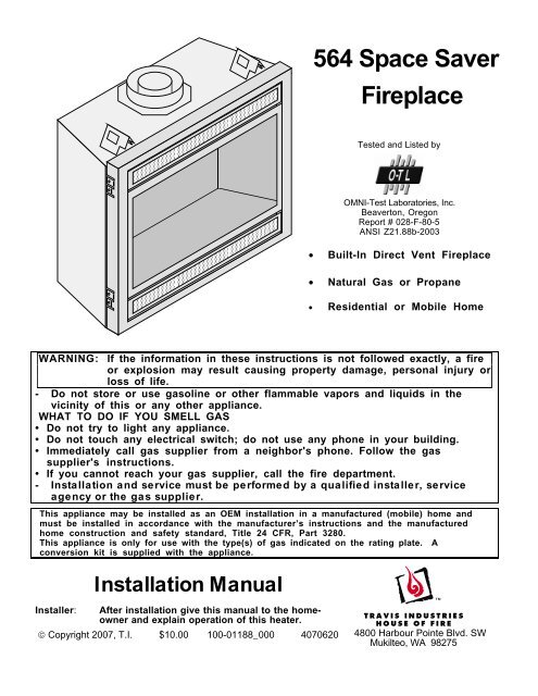
<strong>564</strong> <strong>Space</strong> <strong>Saver</strong><br />
<strong>Fireplace</strong><br />
Tested and Listed by<br />
OMNI-Test Laboratories, Inc.<br />
Beaverton, Oregon<br />
Report # 028-F-80-5<br />
ANSI Z21.88b-2003<br />
• Built-In Direct Vent <strong>Fireplace</strong><br />
• Natural Gas or Propane<br />
• Residential or Mobile Home<br />
WARNING: If the information in these instructions is not followed exactly, a fire<br />
or explosion may result causing property damage, personal injury or<br />
loss of life.<br />
- Do not store or use gasoline or other flammable vapors and liquids in the<br />
vicinity of this or any other appliance.<br />
WHAT TO DO IF YOU SMELL GAS<br />
• Do not try to light any appliance.<br />
• Do not touch any electrical switch; do not use any phone in your building.<br />
• Immediately call gas supplier from a neighbor's phone. Follow the gas<br />
supplier's instructions.<br />
• If you cannot reach your gas supplier, call the fire department.<br />
- Installation and service must be performed by a qualified installer, service<br />
agency or the gas supplier.<br />
This appliance may be installed as an OEM installation in a manufactured (mobile) home and<br />
must be installed in accordance with the manufacturer’s instructions and the manufactured<br />
home construction and safety standard, Title 24 CFR, Part 3280.<br />
This appliance is only for use with the type(s) of gas indicated on the rating plate. A<br />
conversion kit is supplied with the appliance.<br />
Installation Manual<br />
Installer: After installation give this manual to the homeowner<br />
and explain operation of this heater.<br />
© Copyright 2007, T.I. $10.00 100-01188_000 4070620<br />
4800 Harbour Pointe Blvd. SW<br />
Mukilteo, WA 98275
2 Introduction<br />
Overview<br />
This manual details the installation requirements for<br />
the <strong>564</strong> SS fireplace. For operating and<br />
maintenance instructions, refer to the <strong>564</strong> SS<br />
Owner's Manual (part # 100-01189).<br />
Listing Details<br />
This appliance was listed by OMNI Test Labs to<br />
ANSI Z21.88 - report # 028-F-80-5. The listing label<br />
is attached to the appliance near the gas control<br />
valve. A copy is shown to the right.<br />
ICBO Approval<br />
This appliance was listed by OMNI Test Labs - ICBO<br />
# TL130.<br />
Massachusetts Approval<br />
This manual has been submitted to the<br />
Massachusetts Board of State Examiners of<br />
Plumbers and Gas Fitters<br />
National <strong>Fireplace</strong> Institute<br />
© Travis Industries 4070620 100-01188_000
Introduction<br />
Overview.................................................................2<br />
Listing Details ..........................................................2<br />
Safety Precautions<br />
Safety Precautions ...................................................4<br />
Features and Specifications<br />
Features .................................................................6<br />
Installation Options...................................................6<br />
Heating Specifications...............................................6<br />
Dimensions..............................................................6<br />
Installation<br />
Packing List.............................................................7<br />
Additional Items Required...........................................7<br />
Installation Overview.................................................7<br />
Recommended Installation Procedure...........................7<br />
Top Stand-Off Assembly ............................................9<br />
Converting the <strong>Fireplace</strong> to Top Vent Configuration.......10<br />
<strong>Fireplace</strong> Placement Requirements...............................12<br />
Clearances...........................................................12<br />
Raised <strong>Fireplace</strong>s ..................................................12<br />
Min. Framing Dims. - Rear Vent Configuration......................13<br />
Min. Framing Dims. - Top Vent Configuration................14<br />
Nailing Brackets ....................................................15<br />
Corner Installations - Rear Vent Configuration..............16<br />
Corner Installations - Top Vent Configuration...............17<br />
Gas Line Requirements..............................................18<br />
Fuel.....................................................................18<br />
Gas Line Connection ..............................................18<br />
Gas Inlet Pressure.................................................18<br />
Gas Line Location..................................................18<br />
Electrical Connection (required)...................................20<br />
Wall Switch or Thermostat Installation...........................21<br />
Wiring Diagram (Millivolt System)...............................21<br />
Wall Switch Installation ...........................................21<br />
Vent Requirements....................................................22<br />
Vent Clearances....................................................22<br />
Altitude Considerations...........................................22<br />
Approved Vent ......................................................23<br />
Vent Installation ....................................................23<br />
Approved Vent Configurations.....................................24<br />
Restrictor Position .................................................24<br />
Exhaust Restrictor Adjustment.................................24<br />
Intake Restrictor Adjustment....................................25<br />
Diffuser Plate Adjustment........................................26<br />
Rear Vent Config. W Horizontal Term. (no vertical rise) .....27<br />
Rear Vent Config. W Horizontal Term. (w vertical rise).......28<br />
Rear Vent Configuration with Vertical Termination............29<br />
Top Vent Configuration with Horizontal Termination..........30<br />
Top Vent Configuration with Vertical Termination .............31<br />
Termination Requirements ..........................................32<br />
Table of Contents 3<br />
Installation (continued)<br />
Hearth Requirements................................................. 33<br />
Facing Requirements................................................. 34<br />
Drywall Installation.................................................34<br />
Facing Overview....................................................35<br />
Optional Faceplates – Sizing Chart............................35<br />
Thin Facing Installation...........................................36<br />
Thick Facing Installation .........................................38<br />
Thick Facing Installation with FPX Arched Faces..........39<br />
Mantel Requirements................................................. 41<br />
Install Example - Build-Out (Dog-House) w Hor. Term. ...... 42<br />
Install Example - Build-In w Hor. Term. .......................... 43<br />
Finalizing the Installation<br />
Steps for Finalizing the Installation............................... 44<br />
Starting the Pilot Flame...........................................44<br />
Pilot Flame Inspection ............................................44<br />
Air Shutter Adjustment............................................45<br />
Glass Frame Removal and Installation .......................... 46<br />
Log Set Installation................................................... 48<br />
LP Conversion Instructions ........................................ 55<br />
Optional Equipment<br />
Fireback Installation.................................................. 59<br />
Blower (part # 99000156)............................................ 60<br />
Grill Installation........................................................ 63<br />
Remote Control Receiver Installation (2 Options) ............ 64<br />
Accent Light Installation 94400100............................. 65<br />
Index<br />
Index ..................................................................... 70<br />
© Travis Industries 4070620 100-01188_000
4 Safety Precautions<br />
Safety Warnings:<br />
• Failure to follow all of the requirements may result in property damage, bodily injury, or even death.<br />
• This unit must be installed by a qualified installer to prevent the possibility of an explosion.<br />
• This appliance must be installed in accordance with all local codes, if any; if not, in U.S.A. follow ANSI<br />
Z223.1 and NFPA 54(88).<br />
• A manufactured home (USA onl) or mobile home OEM installation must conform with the<br />
Manufactured Home Construction and Safety Standard, Title 24 CFR, Part 3280, or, when such a<br />
standard is not applicable, the Standard for Manufactured Home Installations, ANSI/NCSBCS A225.1,<br />
or Standard for Gas Equipped Recational Vehicles and Mobile Housing, CSA Z240.4. This appliance<br />
may be installed in Manufactured Housing only after the home is site located.<br />
• All exhaust gases must be vented outside the structure of the living-area. Combustion air is drawn<br />
from outside the living-area structure. The venting must not be connected to a chimney flue serving a<br />
separate solid-fuel burning appliance.<br />
• Notify your insurance company before hooking up this fireplace.<br />
• The room heater should be inspected before use and at least annually by a qualified service person.<br />
More frequent cleaning may be required due to excessive lint from carpeting, bedding material, etc.<br />
• The instructions in this manual must be strictly adhered to. Do not use makeshift methods or<br />
compromise in the installation. Improper installation will void the warranty and safety listing.<br />
• This heater is approved for use with natural gas (NG) or propane (LP). Burning the incorrect fuel will<br />
void the warranty and safety listing and may cause an extreme safety hazard. Direct questions about<br />
the type of fuel used to your dealer. Check the label and flame adjust knob on the gas control valve.<br />
• Contact your local building officials to obtain a permit and information on any installation restrictions or<br />
inspection requirements in your area.<br />
• If the flame becomes sooty, dark orange in color, or extremely tall, do not operate the heater. Call your<br />
dealer and arrange for proper servicing.<br />
• It is imperative that control compartments, screens, or circulating air passageways of the heater be<br />
kept clean and free of obstructions. These areas provide the air necessary for safe operation.<br />
• Do not operate the heater if it is not operating properly in any fashion or if you are uncertain. Call your<br />
dealer for a full explanation of your heater and what to expect.<br />
• Do not store or use gasoline or other flammable liquids in the vicinity of this heater.<br />
• Do not operate if any portion of the heater was submerged in water or if any corrosion occurs.<br />
• Do not place clothing or other flammable items on or near the heater. Because this heater can be<br />
controlled by a thermostat there is a possibility of the heater turning on and igniting any items placed<br />
on or near it.<br />
• Light the heater using the built-in piezo igniter. Do not use matches or any other external device to<br />
light your heater.<br />
• Never remove, replace, modify or substitute any part of the heater unless instructions are given in this<br />
manual. All other work must be done by a trained technician. Don't modify or replace orifices.<br />
• The viewing glass should be opened only for lighting the pilot or conducting service.<br />
• Any safety screen or guard removed for servicing must be replaced prior to operating the heater.<br />
Travis Industries 4070620 100-01188_000
Safety Warnings (continued):<br />
Safety Precautions 5<br />
• Allow the heater to cool before carrying out any maintenance or cleaning.<br />
• Operate the heater according to the instructions included in this manual.<br />
• If the main burners do not start correctly turn the gas off at the gas control valve and call your dealer for<br />
service.<br />
• The pilot flame must contact the thermopile and thermocouple. If it does not, turn the gas control<br />
valve to "OFF" and call your dealer.<br />
• This unit is not for use with solid fuel.<br />
• Do not place anything inside the firebox (except the included fiber logs).<br />
• If the fiber logs become damaged, replace with Travis Industries log set.<br />
• Do not throw this manual away. This manual has important operating and maintenance instructions<br />
that you will need at a later time. Always follow the instructions in this manual.<br />
• Do not touch the hot surfaces of the heater. Educate all children of the danger of a high-temperature<br />
heater. Young children should be supervised when they are in the same room as the heater.<br />
• Due to the high temperature, the heater should be located out of traffic and away from furniture and<br />
draperies.<br />
• Instruct everyone in the house how to shut gas off to the appliance and at the gas main shutoff valve.<br />
The gas main shutoff valve is usually next to the gas meter or propane tank and requires a wrench to<br />
shut off.<br />
• Travis Industries, Inc. grants no warranty, implied or stated, for the installation or<br />
maintenance of your heater, and assumes no responsibility of any consequential<br />
damage(s).<br />
© Travis Industries 4070620 100-01188_000
6 Features and Specifications<br />
Installation Options<br />
• Residential or Mobile Home<br />
• Straight or Corner Placement<br />
• Flush or Recessed Face<br />
Heating Specifications<br />
• Raised or Floor Placement<br />
• Internal or External Chase<br />
• Horizontal or Vertical Vent<br />
• Bedroom Approved<br />
Natural Gas Propane<br />
Approximate Heating Capacity (in square feet)* 950 950<br />
Maximum BTU Input Per Hour 20,500 20,500<br />
Steady State Efficiency** (with optional blowers on)** 76.5 % 74.2 %<br />
* Heating capacity will vary with floor plan, insulation, and outside temperature.<br />
** Efficiency rating is a product thermal efficiency rating determined under continuous operation<br />
independent of installed system.<br />
Dimensions<br />
30"*<br />
16-1/4"*<br />
Top Vent Configuration<br />
8" Diameter Vent<br />
4-3/4"<br />
31-3/4"<br />
* Includes the required 1/2" clearance.<br />
<br />
<br />
<br />
<br />
<br />
<br />
<br />
32-1/2"<br />
<br />
<br />
<br />
<br />
<br />
36-1/4"<br />
<br />
Left<br />
18-3/4"<br />
28-3/4"<br />
30-1/4"<br />
33-1/4"<br />
Rear Vent Configuration<br />
8" Diameter Vent<br />
Weight: 155 Lbs.<br />
Back of <strong>Fireplace</strong><br />
Travis Industries 4070620 100-01188_000<br />
1"<br />
Right<br />
Front<br />
24-1/4"
Packing List<br />
• Propane Conversion Kit<br />
• Log Set<br />
Additional Items Required<br />
Installation (for qualified installers only) 7<br />
• Direct Vent<br />
• Gas Line Equipment (shutoff valve, pipe, etc.)<br />
• Electrical Equipment (min. 14 gauge, grounded line)<br />
Installation Overview<br />
Top Vent<br />
Configuration<br />
• All requirements below must be met.<br />
See the section<br />
"Mantel Requirements"<br />
Side<br />
Wall<br />
See "Optional Non-<br />
Combustible Facing"<br />
<br />
<br />
<br />
<br />
<br />
<br />
<br />
<br />
<br />
Drywall <br />
<br />
1" Min. <br />
<br />
<br />
<br />
<br />
<br />
<br />
<br />
<br />
<br />
<br />
Drywall<br />
<br />
<br />
See "Optional Non-<br />
Combustible Hearth"<br />
See the section<br />
"Electrical Connection"<br />
• Wall Switch with Wire (see page 21 for details)<br />
• Firestop (sku 250-00747)<br />
See the section<br />
"Vent Requirements"<br />
Recommended Installation Procedure<br />
See the section<br />
"Approved Vent<br />
Configurations"<br />
Insulation must not fill<br />
the 1/2" clearance<br />
around the back and<br />
sides of the fireplace.<br />
Nailing Brackets<br />
See the section "Minimum<br />
Framing Dimensions"<br />
See the section<br />
"Gas Line Installation"<br />
Rear Vent<br />
Configuration<br />
Required Travis<br />
Firestop (sku<br />
250-00747)<br />
1 Frame the opening for the fireplace. Make sure to allow for vent installation.<br />
2 This fireplace is designed to accommodate 1/2" or 5/8" drywall (see "Nailing Brackets" on page 15<br />
for details). Secure the fireplace to the framing.<br />
3 Install the vent, gas line and electrical hook-up.<br />
4 Install the wall switch (see page 21) or thermostat (if applicable).<br />
5 Install the drywall.<br />
6 Install the hearth (if applicable).<br />
7 Install the facing (if applicable).<br />
8 Install the mantel (if applicable).<br />
9 Finalize the installation (see page 44) and install the grill or face.<br />
© Travis Industries 4070620 100-01188_000
8 Installation (for qualified installers only)<br />
Massachusetts Requirements<br />
NOTE: The following requirements reference various Massachusetts and national codes not contained in this document.<br />
Requirements for the Commonwealth of Massachusetts<br />
For all side wall horizontally vented gas fueled equipment installed in every dwelling, building or structure used in whole or in<br />
part for residential purposes, including those owned or operated by the Commonwealth and where the side wall exhaust vent<br />
termination is less than seven (7) feet above finished grade in the area of the venting, including but not limited to decks and<br />
porches, the following requirements shall be satisfied:<br />
Installation of Carbon Monoxide Detectors<br />
At the time of installation of the side wall horizontal vented gas fueled equipment, the installing plumber or gasfitter shall<br />
observe that a hard wired carbon monoxide detector with an alarm and battery back-up is installed on the floor level where the<br />
gas equipment is to be installed. In addition, the installing plumber or gasfitter shall observe that a battery operated or hard<br />
wired carbon monoxide detector with an alarm is installed on each additional level of the dwelling, building or structure served<br />
by the side wall horizontal vented gas fueled equipment. It shall be the responsibility of the property owner to secure the<br />
services of qualified licensed professionals for the installation of hard wired carbon monoxide detectors.<br />
In the event that the side wall horizontally vented gas fueled equipment is installed in a crawl space or an attic, the hard wired<br />
carbon monoxide detector with alarm and battery back-up may be installed on the next adjacent floor level.<br />
In the event that the requirements of this subdivision can not be met at the time of completion of installation, the owner shall<br />
have a period of thirty (30) days to comply with the above requirements; provided, however, that during said thirty (30) day<br />
period, a battery operated carbon monoxide detector with an alarm shall be installed.<br />
Approved Carbon Monoxide Detectors<br />
Each carbon monoxide detector as required in accordance with the above provisions shall comply with NFPA 720 and be<br />
ANSI/UL 2034 listed and IAS certified.<br />
Signage<br />
A metal or plastic identification plate shall be permanently mounted to the exterior of the building at a minimum height of eight<br />
(8) feet above grade directly in line with the exhaust vent terminal for the horizontally vented gas fueled heating appliance or<br />
equipment. The sign shall read, in print size no less than one-half (1/2) inch in size, “GAS VENT DIRECTLY BELOW. KEEP<br />
CLEAR OF ALL OBSTRUCTIONS”.<br />
Inspection<br />
The state or local gas inspector of the side wall horizontally vented gas fueled equipment shall not approve the installation<br />
unless, upon inspection, the inspector observes carbon monoxide detectors and signage installed in accordance with the<br />
provisions of 248 CMR 5.08(2)(a)1 through 4.<br />
Exemptions<br />
The following equipment is exempt from 248 CMR 5.08(2)(a)1 through 4:<br />
• The equipment listed in Chapter 10 entitled “Equipment Not Required To Be Vented” in the most current edition of NFPA 54 as<br />
adopted by the Board; and<br />
• Product Approved side wall horizontally vented gas fueled equipment installed in a room or structure separate from the<br />
dwelling, building or structure used in whole or in part for residential purposes.<br />
MANUFACTURER REQUIREMENTS<br />
Gas Equipment Venting System Provided<br />
When the manufacturer of Product Approved side wall horizontally vented gas equipment provides a venting system design or<br />
venting system components with the equipment, the instructions provided by the manufacturer for installation of the<br />
equipment and the venting system shall include:<br />
• Detailed instructions for the installation of the venting system design or the venting system components; and<br />
• A complete parts list for the venting system design or venting system.<br />
Gas Equipment Venting System NOT Provided<br />
When the manufacturer of a Product Approved side wall horizontally vented gas fueled equipment does not provide the parts<br />
for venting the flue gases, but identifies “special venting systems”, the following requirements shall be satisfied by the<br />
manufacturer:<br />
• The referenced “special venting system” instructions shall be included with the appliance or equipment installation<br />
instructions; and<br />
• The “special venting systems” shall be Product Approved by the Board, and the instructions for that system shall include a<br />
parts list and detailed installation instructions.<br />
A copy of all installation instructions for all Product Approved side wall horizontally vented gas fueled equipment, all venting<br />
instructions, all parts lists for venting instructions, and/or all venting design instructions shall remain with the appliance or<br />
equipment at the completion of the installation.<br />
See Gas Connection section for additional Commonwealth of Massachusetts requirements.<br />
Travis Industries 4070620 100-01188_000
Top Stand-Off Assembly<br />
Installation (for qualified installers only) 9<br />
The top stand-offs must be assembled prior to installation.<br />
Warning: You must follow the instructions below to elevate both standoffs. Failure to<br />
do so will result in an extreme fire hazard.<br />
AFTER<br />
BEFORE<br />
Standoff<br />
<br />
<br />
<br />
<br />
<br />
a<br />
<br />
<br />
<br />
b<br />
<br />
<br />
<br />
The standoffs are shipped in the flat position.<br />
Make sure to follow the instructions below before<br />
installing the fireplace.<br />
Bend the standoff in the numbered<br />
sequence shown above.<br />
Remove the screw below the standoff.<br />
Replace the screw to secure the standoff.<br />
© Travis Industries 4070620 100-01188_000<br />
c<br />
1<br />
2<br />
3<br />
1/4" Nutdriver
10 Installation (for qualified installers only)<br />
Top Vent or Rear Vent Configuration<br />
This appliance is shipped in the rear vent configuration. To change to the top vent configuration, follow<br />
the directions below.<br />
NOTE : the vent configuration affects several aspects of installation (framing, maximum vent rise,<br />
maximum vent run). Make sure the vent configuration is correct prior to installation. You may wish to<br />
configure the diffuser when changing the vent configuration.<br />
Converting the <strong>Fireplace</strong> to Top Vent Configuration<br />
Remove and discard the<br />
heat shield. Replace the 4<br />
removed screws.<br />
Top of <strong>Fireplace</strong><br />
Remove the 4 screws securing the<br />
intake cover plate. Place the screws<br />
and cover plate aside.<br />
Back of <strong>Fireplace</strong><br />
<br />
<br />
<br />
NOTE: Use a magnetic-tipped<br />
nutdriver on these screws - take<br />
care to prevent the screws from<br />
falling into the fireplace.<br />
Remove the 4 screws securing the<br />
outer flue assembly. Place the<br />
screws and assembly aside.<br />
<br />
<br />
<br />
<br />
<br />
<br />
<br />
<br />
Remove the 4 screws securing the<br />
inner flue assembly. Place the<br />
screws and assembly aside.<br />
Remove and discard the<br />
insulation found below the<br />
large cover plate.<br />
Travis Industries 4070620 100-01188_000
Installation (for qualified installers only) 11<br />
Converting the <strong>Fireplace</strong> to Top Vent (continued)<br />
Remove the 4 screws securing the<br />
exhaust cover plate. Verify the gasket<br />
on the cover plate is in place, then<br />
attach it to the rear-facing exhaust<br />
port with the same screws.<br />
Verify the gasket on the inner flue<br />
assembly is in place, then attach it to<br />
the upward-facing exhaust port using<br />
the screws removed earlier.<br />
Verify the gasket on the intake cover<br />
plate is in place, then attach it to the<br />
rear of the fireplace using the screws<br />
removed earlier.<br />
Verify the gasket on the outer flue<br />
assembly is in place, then attach it to<br />
the top of the fireplace using the<br />
screws removed earlier.<br />
© Travis Industries 4070620 100-01188_000
12 Installation (for qualified installers only)<br />
<strong>Fireplace</strong> Placement Requirements<br />
• The fireplace requires a 1/2" clearance from the angled sides and back of the fireplace to the framing<br />
members. No material (insulation, framing, etc.) may be placed into this area.<br />
• <strong>Fireplace</strong> must be installed on a level surface capable of supporting the fireplace and vent<br />
• <strong>Fireplace</strong> must be placed directly on wood or non-combustible surface (not on linoleum or carpet)<br />
• This heater may be placed in a bedroom. Please be aware of the large amount of heat this appliance<br />
produces when determining a location.<br />
Clearances<br />
• When installed, walls in front of the fireplace must be a minimum 1" to the side of the fireplace.<br />
• Due to the high temperature, the heater should be located out of traffic and away from furniture and<br />
draperies.<br />
• <strong>Fireplace</strong> must be placed so the vents below and above the glass do not become blocked.<br />
Raised <strong>Fireplace</strong>s<br />
• The fireplace (and hearth, if desired) may be placed on a platform designed to support the fireplace<br />
(155 Lbs.) and vent.<br />
Travis Industries 4070620 100-01188_000
Installation (for qualified installers only) 13<br />
Minimum Framing Dimensions - Rear Vent Configuration<br />
HINT: place the fireplace so the center<br />
line is at least 5" from both vertical framing<br />
members at the rear (this allows the vent<br />
to pass through the framing without<br />
modfications)<br />
Minimum 38” <strong>Fireplace</strong><br />
Route the<br />
electrical line to<br />
a position to the<br />
left rear of the<br />
fireplace.<br />
Enclosure Height<br />
33-1/2"<br />
36-1/2"<br />
Included Firestop (required)<br />
Part # 250-00747<br />
<br />
<br />
<br />
<br />
<br />
<br />
<br />
<br />
19-1/4"<br />
32-1/2"<br />
Vent Clearances (8" dia. Vent):<br />
1" to the sides, 1" below, and 4" above<br />
the vent to combustibles.<br />
16-1/2"<br />
Center of Rear Vent<br />
24-1/4"<br />
The on/off switch/thermostat wire (if<br />
used) should be routed to a location<br />
near the right front of the fireplace.<br />
© Travis Industries 4070620 100-01188_000
14 Installation (for qualified installers only)<br />
Minimum Framing Dimensions - Top Vent Configuration<br />
Route the electrical line to<br />
a position to the left rear<br />
of the fireplace.<br />
Minimum enclosure height = 36-1/4"<br />
33-1/2"<br />
36-1/2"<br />
16-1/2"<br />
WARNING: A cut-out for the gas line<br />
may be required on the framing. See<br />
the dimensions under "Gas Line<br />
Connection" for details.<br />
The on/off switch/thermostat wire (if<br />
used) should be routed to a location<br />
near the right front of the fireplace.<br />
Travis Industries 4070620 100-01188_000
Nailing Brackets<br />
There are four nailing brackets<br />
on the front of the fireplace.<br />
Follow the directions below to<br />
prepare the nailing brackets.<br />
Once in place, nail or screw the<br />
nailing brackets to the framing.<br />
NOTE: Additional nailing<br />
brackets are provided along<br />
the base of the fireplace.<br />
Use these brackets if not<br />
using the front brackets.<br />
1/2” Drywall<br />
For installations using<br />
1/2” facing fold the larger<br />
tab out 90° (use a<br />
screwdriver if necessary).<br />
5/8” Drywall<br />
For installations using<br />
5/8” drywall fold the<br />
shorter tab out 90° (use<br />
a screwdriver if<br />
necessary).<br />
Installation (for qualified installers only) 15<br />
TOP VIEW<br />
<strong>Fireplace</strong><br />
TOP VIEW<br />
<strong>Fireplace</strong><br />
WARNING:<br />
Make sure the fireplace is<br />
square and plumb when<br />
placed in the framing.<br />
Measured corner-to-<br />
corner, the fireplace<br />
should be square (approx.<br />
47-1/8” for each<br />
dimension). Use shims to<br />
insure the fireplace is<br />
square.<br />
Framing<br />
Nailing Bracket<br />
Drywall<br />
<br />
<br />
Framing<br />
Nailing Bracket<br />
Drywall<br />
<br />
© Travis Industries 4070620 100-01188_000
16 Installation (for qualified installers only)<br />
Corner Installations - Rear Vent Configuration<br />
A typical 45° installation uses the framing dimensions shown in the illustration below (NOTE: all clearances<br />
still apply).<br />
7" Approximate<br />
(varies due to vent<br />
installation)<br />
NOTE: Most<br />
installations use:<br />
6" Section for 2x6 Walls<br />
4" Section for 2x4 Walls<br />
44-1/2" Min.<br />
Minimum 1" Clearance<br />
<strong>564</strong> SS Firestop<br />
Minimum 1/2" Clearance<br />
<br />
<br />
<br />
<br />
<br />
<br />
<br />
<br />
<br />
<br />
<br />
<br />
<br />
<br />
<br />
<br />
<br />
<br />
<br />
<br />
<br />
<br />
<br />
Travis Industries 4070620 100-01188_000
Installation (for qualified installers only) 17<br />
Corner Installations - Top Vent Configuration<br />
A typical 45° installation uses the framing dimensions shown in the illustration below (NOTE: all clearances<br />
still apply).<br />
44-1/2"<br />
Min.<br />
14-1/4"<br />
Minimum 1/2" Clearance<br />
<br />
<br />
<br />
<br />
<br />
<br />
<br />
<br />
<br />
<br />
<br />
<br />
<br />
<br />
<br />
<br />
<br />
<br />
<br />
<br />
<br />
<br />
<br />
<br />
<br />
<br />
<br />
<br />
<br />
<br />
<br />
<br />
<br />
<br />
<br />
© Travis Industries 4070620 100-01188_000
18 Installation (for qualified installers only)<br />
Gas Line Requirements<br />
Fuel<br />
MASSACHUSETTS INSTALLATIONS -<br />
WARNING:<br />
THIS PRODUCT MUST BE INSTALLED BY A LICENSED PLUMBER OR GAS FITTER WHEN INSTALLED WITHIN THE<br />
COMMONWEALTH OF MASSACHUSETTS.<br />
OTHER MASSACHUSETTS CODE REQUIREMENTS:<br />
• Flexible connector must not be longer than 36 inches.<br />
• Shutoff valve must be a “T” handle gas cock.<br />
• Only direct vent sealed combustion products are approved for bedrooms or bathrooms.<br />
• <strong>Fireplace</strong> dampers must be removed or welded in the open position prior to the installation of a fireplace insert or gas log.<br />
• A carbon monoxide (CO) detector is required in the same room as the appliance.<br />
• The gas line must be installed in accordance with all local codes, if any; if not, follow ANSI 223.1 and<br />
the requirements listed below.<br />
• The fireplace and gas control valve must be disconnected from the gas supply piping during any<br />
pressure testing of that system at test pressures in excess of 1/2 psig. For pressures under 1/2 psig,<br />
isolate the gas supply piping by closing the manual shutoff valve.<br />
• Leak test all gas line joints and the gas control valve prior to and after starting the fireplace.<br />
• This fireplace is designed either for natural gas or for propane (but not for both). Check the sticker on the top of<br />
the gas control valve to make sure the correct fuel is used (see illustration on page 4).<br />
Gas Line Connection<br />
• Installation must be performed by a qualified installer, service agency or the gas supplier (In Massachusetts a<br />
licensed plumber/gasfitter).<br />
Standard Input Pressure<br />
Gas Inlet Pressure<br />
Natural Gas 7" W.C. (1.74 kPA)<br />
Propane 13" W.C. (2.73 kPA)<br />
• If the pressure is not sufficient, make sure the piping used is large enough, the supply regulator is adequately<br />
adjusted, and the total gas load for the residence does not exceed the amount supplied.<br />
• The supply regulator (the regulator that attaches directly to the residence inlet or to the propane tank) should<br />
supply gas at the suggested input pressure listed above. Contact the local gas supplier if the regulator is at an<br />
improper pressure.<br />
Travis Industries 4070620 100-01188_000
Gas Line Location<br />
Right Side Gas Inlet (preferred)<br />
A 12" flex tube and shutoff valve is<br />
included with the fireplace. The<br />
shutoff valve accepts a 1/2"MPT.<br />
Left Side Gas Inlet<br />
A 3" high by 2" wide opening is located<br />
behind the gas inlet cover plate (it is 1-3/4"<br />
above the base of the fireplace).<br />
Installation (for qualified installers only) 19<br />
You may remove this cover plate to<br />
install the gas line. The cover plate has<br />
a 7/8" diameter hole (covered with a<br />
push plug). By rotating the plate 180°<br />
the hole may be re-located. You may<br />
also secure the plate in a customized<br />
location using the self-drilling screws.<br />
© Travis Industries 4070620 100-01188_000<br />
13-1/2"<br />
A 3" high by 2" wide opening is located<br />
behind the gas inlet cover plate (it is 1-3/4"<br />
above the base of the fireplace).<br />
6"<br />
13-1/2"<br />
The gas inlet is located 2-1/2"<br />
above the base of the fireplace.<br />
You may remove this cover plate to install the gas line. The<br />
cover plate has a 7/8" diameter hole (covered with a push<br />
plug) in line with the gas inlet on the gas control valve. By<br />
rotating the plate 180° the hole may be re-located. You may<br />
also secure the plate in a customized location using the selfdrilling<br />
screws.<br />
A 12" flex tube and shutoff valve is<br />
included with the fireplace (you may<br />
wish to use a 24" flex tube). The<br />
shutoff valve accepts a 1/2" MPT.<br />
6"
20 Installation (for qualified installers only)<br />
Electrical Connection (required)<br />
• The electrical line to the grounded receptacle inside the fireplace must be installed by a qualified<br />
installer and must meet all local codes.<br />
• Make sure the household breaker is shut off prior to working on any electrical lines.<br />
• The appliance, when installed, must be electrically grounded in accordance with local codes or, in the<br />
absence of local codes, with the National Electrical Code, ANSI/NFPA 70, or the Canadian Electrical Code,<br />
CSA C22.1.<br />
• The electrical line must be a min. 14 gauge, and supply 120 Volts at 60 Hz (2 Amps)<br />
Caution : Label all wires prior to disconnection when servicing controls. Wiring errors can cause<br />
improper and dangerous operation.<br />
Junction Box Assembly<br />
Grounded 110V<br />
Power Supply<br />
Grounded Receptacle<br />
Strain Relief<br />
Left Side of <strong>Fireplace</strong><br />
Receptacle Cover Plate<br />
Travis Industries 4070620 100-01188_000
Installation (for qualified installers only) 21<br />
Wall Switch or Thermostat Installation<br />
Wiring Diagram (Millivolt System)<br />
Do not connect 110-120 VAC to the gas control valve or wiring system of this fireplace. The switch must<br />
be installed by a qualified installer.<br />
The included wall switch may be installed following the directions below. An optional thermostat may also<br />
be installed. It is attached to the gas control valve in the same manner.<br />
Caution : Label all wires prior to disconnection when servicing controls. Wiring errors can cause<br />
improper and dangerous operation.<br />
Red<br />
On/Off Switch (on fireplace)<br />
Wall Switch Installation<br />
Brown<br />
Copper Co-Axial<br />
Wire<br />
1. Attach the included wire to the gas control valve.<br />
Attach the two wires to the top and<br />
bottom posts on the gas control<br />
valve (orientation does not matter).<br />
Thermocouple<br />
Red<br />
© Travis Industries 4070620 100-01188_000<br />
White<br />
Thermopile<br />
<br />
Optional Wall Switch,<br />
Thermostat, or<br />
Remote Control<br />
Piezo Igniter<br />
Spark Electrode<br />
Pilot Hood<br />
Orange<br />
2. Determine a location for the wall switch (the wire is a maximum 25' long). Route the wire through the gas<br />
inlet hole (either side) to the junction box and attach following the directions below. Set the on/off<br />
switch on the appliance to "OFF" to control the appliance with the wall switch.<br />
a<br />
Insert the wire<br />
through the back of<br />
the mounted<br />
junction box (your<br />
junction box may<br />
look different).<br />
Expose 1/2" of<br />
each wire. Secure<br />
the wires to the<br />
posts on the side of<br />
the on/off switch<br />
(orientation does<br />
not matter).<br />
Standard<br />
Screwdriver<br />
From<br />
Appliance<br />
b<br />
Carefully pack the wires into the<br />
junction box. Attach the switch<br />
to the junction box. Attach the<br />
switchplate to the switch.<br />
Standard<br />
Screwdriver
22 Installation (for qualified installers only)<br />
Vent Requirements<br />
• The gas appliance and vent system must be vented directly to the outside of the building, and never<br />
be attached to a chimney serving a separate solid fuel or gas-burning appliance. Each direct vent gas<br />
appliance must use it's own separate vent system.<br />
• In addition to the requirements listed here, follow the requirements provided with the vent.<br />
• A firestop is required whenever the vent penetrates a wall, floor, or ceiling (passes through framing<br />
members). Horizontal vent less than 48" above the fireplace must use the Travis Firestop (sku 250-<br />
00747 - it incorporates a 4" clearance above, 1" clearance below and to the sides of the vent). Other<br />
penetrations only require a 1" clearance and may use a standard firestop (make sure the required 1"<br />
clearance is met).<br />
• Always use the high-wind termination (if available from the vent manufacturer).<br />
Vent Clearances<br />
• The vent must maintain the required clearance to combustible materials to prevent a fire. Do not fill air<br />
spaces with insulation.<br />
Before 48" Rise After 48" Rise<br />
Sides 1" 1"<br />
Above 4" 1"<br />
Below Horizontal or 45° Section 1" 1"<br />
Vertical Termination<br />
Use a roof flashing and storm collar<br />
whenever passing through the roof<br />
Use a firestop whenever<br />
passing through a ceiling<br />
Use a support box<br />
on exposed vent<br />
Altitude Considerations<br />
Min. 1"<br />
Required Firestop<br />
Horizontal<br />
Termination<br />
Min. 4"<br />
(1" if a minimum 48"<br />
above the fireplace)<br />
• This heater has been tested at altitudes ranging from sea level to 6,000 feet. In this testing we have found that<br />
the heater, with its standard orifice, burns correctly with just an air shutter adjustment.<br />
• Failure to adjust the air shutter properly may lead to improper combustion which can create a safety hazard.<br />
Consult your dealer or installer if you suspect an improperly adjusted air shutter.<br />
Travis Industries 4070620 100-01188_000<br />
Min. 1"<br />
Min. 1"
Approved Vent<br />
Installation (for qualified installers only) 23<br />
• Rear vent configurations use 8" diameter Simpson Dura-Vent Model GS vent.<br />
• Top vent configurations use 8" or 6-5/8" diameter Simpson Dura-Vent Model GS vent. If using 6-5/8"<br />
diameter vent, attach the 8" to 6-5/8" reducer (Travis part # 98900165) to the fireplace.<br />
NOTE: When using 6-5/8” diameter vent, make sure to accommodate the 4” clearance above the vent<br />
for the first 48” of rise (see vent clearances on page 22). Standard firestops do not include this<br />
clearance.<br />
• Installation instructions for Simpson Dura-Vent may be found at www.duravent.com<br />
Vent Installation<br />
6-5/8" Diameter Vent<br />
Reducer - # 98900165<br />
• Slide the vent sections together and turn 1/4 turn until the sections lock in<br />
place.<br />
• Screws are not required to secure the vent. However, three screws may be<br />
used to secure vent sections together if desired.<br />
• High temperature sealant is recommended at the appliance starter section<br />
connection (use high-temperature silicone or Mill-Pac®).<br />
• If disassembly is required, at time of re-assembly check to see if the vent<br />
creates a tight fit. If it does not, apply high temperature sealant to the joints of<br />
the affected sections.<br />
• Horizontal sections require a 1/4" rise every 12" of travel<br />
• Horizontal sections require non-combustible support every three feet (e.g.: plumbing tape)<br />
© Travis Industries 4070620 100-01188_000
24 Installation (for qualified installers only)<br />
Approved Vent Configurations<br />
Restrictor Position<br />
• Intake and exhaust restrictors are built into the appliance to adjust the flow rate of intake air and<br />
exhaust gases. Depending upon the vent configuration, you may be required to adjust the restrictor<br />
positions. The charts for acceptable vent configurations detail the correct vent restrictor positions.<br />
Exhaust Restrictor Adjustment<br />
If the diffuser is required to be in position # 2, you may wish to adjust the diffuser while the exhaust<br />
restrictor is removed.<br />
(closed) #6<br />
# 5<br />
# 4<br />
# 3<br />
# 2<br />
# 1<br />
(open - stock position) # 0<br />
Firebox RoofThe exhaust restrictor is shipped<br />
Back Wall of Firebox<br />
in postion # 0. If the restritor is<br />
required in a different postion,<br />
remove the screws, re-position<br />
the restrictor (see the illustration<br />
below), and replace the screws.<br />
In this example, the restrictor is<br />
set in position # 3.<br />
Back of Firebox<br />
Travis Industries 4070620 100-01188_000
Intake Restrictor Adjustment<br />
Installation (for qualified installers only) 25<br />
<br />
<br />
<br />
<br />
<br />
Position # 1 (open)<br />
1/4”<br />
Socket<br />
Loosen the two screws<br />
holding the intake<br />
restrictor in place..<br />
Position # 2 (closed)<br />
Slide the restrictor down<br />
to the lower position and<br />
tighten the screws.<br />
© Travis Industries 4070620 100-01188_000
26 Installation (for qualified installers only)<br />
Diffuser Plate Adjustment<br />
Certain vent configurations require the diffuser plate to be adjusted (refer to the approved vent<br />
configuration charts for details). Position # 1 is stock (bent). Position # 2 is flattened. See the directions<br />
below to change the diffuser to position #2.<br />
DIFFUSER SIDE VIEW<br />
Before (Stock - Position # 1)<br />
After (Position # 2)<br />
Firebox Roof<br />
Back Wall of Firebox<br />
<br />
<br />
<br />
1/4" Nutdriver<br />
Remove the exhaust<br />
restrictor.<br />
1/4" Nutdriver<br />
Remove the diffuser.<br />
Bend the round portion of the<br />
diffuser so it is flat (position # 2).<br />
Secure the flattened<br />
diffuser plate with the<br />
screws removed earlier.<br />
Replace the exhaust<br />
restrictor (see “Exhaust<br />
Restrictor Adjustment”<br />
for restrictor settings).<br />
Travis Industries 4070620 100-01188_000
Installation (for qualified installers only) 27<br />
Rear Vent Configuration with Horizontal Termination (no vertical rise)<br />
• The termination must fall within the shaded area shown in the chart. Use the indicated restrictor and<br />
diffuser positions.<br />
Optional 45° Elbow<br />
Vent with No 45° Elbow<br />
3 feet<br />
0 feet<br />
Vent with 1 45° Elbow<br />
3 feet<br />
0 feet<br />
0 feet<br />
0 feet<br />
See the charts below to<br />
determine maximum vent<br />
2' (max)<br />
4' (max)<br />
Termination<br />
• Exhaust Restrictor # 0 (stock)<br />
• Intake Restrictor # 1 (stock)<br />
• Diffuser Position # 1 (stock)<br />
• Min. 4" Horizontal Section<br />
• Max.48" Horizontal Section(s)<br />
• Exhaust Restrictor # 0 (stock)<br />
• Intake Restrictor # 1 (stock)<br />
• Diffuser Position # 1 (stock)<br />
• Min. 4" Horizontal Section<br />
• Max. 24" Horizontal Section(s)<br />
© Travis Industries 4070620 100-01188_000
28 Installation (for qualified installers only)<br />
Rear Vent Configuration with Horizontal Termination (with vertical<br />
rise)<br />
• The termination must fall within the shaded area shown in the chart. Use the indicated restrictor and<br />
diffuser positions.<br />
• Up to four elbows (45° or 90°) may be used.<br />
• Only one horizontal elbow may be used.<br />
22' (max)<br />
5 feet<br />
0 feet<br />
0 feet<br />
<br />
<br />
<br />
<br />
<br />
<br />
Exhaust Restrictor # 6<br />
<br />
<br />
<br />
Intake Restrictor # 2<br />
<br />
<br />
<br />
Diffuser Position # 2<br />
<br />
<br />
<br />
<br />
<br />
<br />
<br />
<br />
<br />
Exhaust Restrictor # 4<br />
<br />
<br />
<br />
Intake Restrictor # 2<br />
Diffuser Position # 2<br />
<br />
<br />
<br />
<br />
<br />
<br />
Exhaust Restrictor # 2<br />
<br />
Intake Restrictor # 1 (stock)<br />
Diffuser Position # 1 (stock)<br />
<br />
<br />
<br />
<br />
20 feet 20 feet<br />
15 feet<br />
10 feet<br />
0 feet<br />
This is considered a horizontal<br />
elbow (it does not matter<br />
whether it turns right or left).<br />
It may be a 90° or 45° elbow.<br />
5 feet<br />
5 feet<br />
H2<br />
H1<br />
Travis Industries 4070620 100-01188_000<br />
10 feet<br />
10 feet<br />
15 feet<br />
15 feet<br />
This is considered a<br />
vertical elbow<br />
20' (max)<br />
20' (max)<br />
Horizontal length is calculated by adding<br />
both lengths of horizontal run<br />
(Horizontal Length = H1 + H2).<br />
22' (max)<br />
15 feet<br />
10 feet<br />
5 feet<br />
0 feet
Installation (for qualified installers only) 29<br />
Rear Vent Configuration with Vertical Termination<br />
• The termination must fall<br />
within the shaded area shown<br />
in the chart. Use the indicated<br />
restrictor and diffuser<br />
positions.<br />
• Up to four elbows (45° or 90°)<br />
may be used.<br />
• Only one horizontal elbow<br />
may be used.<br />
This is considered a horizontal<br />
elbow (it does not matter<br />
whether it turns right or left).<br />
It may be a 90° or 45° elbow.<br />
40' (max)<br />
35 feet<br />
30 feet<br />
25 feet<br />
5 feet<br />
0 feet<br />
<br />
<br />
<br />
<br />
<br />
<br />
<br />
<br />
<br />
<br />
<br />
Exhaust Restrictor # 4<br />
<br />
Intake Restrictor # 2<br />
<br />
Diffuser Position # 2<br />
<br />
<br />
<br />
<br />
<br />
<br />
<br />
<br />
<br />
<br />
<br />
<br />
<br />
© Travis Industries 4070620 100-01188_000<br />
0 feet<br />
20 feet 20 feet<br />
15 feet<br />
10 feet<br />
H2<br />
H1<br />
0 feet<br />
5 feet<br />
5 feet<br />
10 feet<br />
10 feet<br />
15 feet<br />
15 feet<br />
Horizontal length is calculated by adding<br />
both lengths of horizontal run<br />
(Horizontal Length = H1 + H2).<br />
This is considered a<br />
vertical elbow<br />
20' (max)<br />
20' (max)<br />
40' (max)<br />
35 feet<br />
30 feet<br />
25 feet<br />
15 feet<br />
10 feet<br />
5 feet<br />
0 feet
30 Installation (for qualified installers only)<br />
Top Vent Configuration with Horizontal Termination<br />
• The termination must fall within the shaded area shown in the chart. Use the indicated restrictor and<br />
diffuser positions.<br />
• Up to four elbows (45° or 90°) may be used.<br />
• May use 8" or 6-5/8" diameter vent (see page for 22 details).<br />
• Only one horizontal elbow may be used.<br />
21' (max)<br />
5 feet<br />
0 feet<br />
0 feet<br />
<br />
<br />
<br />
<br />
<br />
<br />
<br />
<br />
Exhaust Restrictor # 6<br />
<br />
<br />
<br />
<br />
Intake Restrictor # 2<br />
<br />
<br />
<br />
<br />
Diffuser Position # 2<br />
<br />
<br />
<br />
<br />
<br />
<br />
<br />
<br />
Exhaust Restrictor # 4<br />
<br />
<br />
<br />
Intake Restrictor # 2<br />
Diffuser Position # 2<br />
<br />
<br />
<br />
<br />
<br />
Exhaust Restrictor # 2<br />
<br />
<br />
Intake Restrictor # 1 (stock)<br />
<br />
Diffuser Position # 1 (stock)<br />
<br />
<br />
<br />
<br />
20 feet 20 feet<br />
15 feet<br />
10 feet<br />
0 feet<br />
This is considered a horizontal<br />
elbow (it does not matter<br />
whether it turns right or left).<br />
It may be a 90° or 45° elbow.<br />
5 feet<br />
5 feet<br />
H2<br />
H1<br />
Travis Industries 4070620 100-01188_000<br />
10 feet<br />
10 feet<br />
15 feet<br />
15 feet<br />
This is considered a<br />
vertical elbow<br />
20' (max)<br />
20' (max)<br />
Horizontal length is calculated by adding<br />
both lengths of horizontal run<br />
(Horizontal Length = H1 + H2).<br />
21' (max)<br />
15 feet<br />
10 feet<br />
5 feet<br />
0 feet
Installation (for qualified installers only) 31<br />
Top Vent Configuration with Vertical Termination<br />
• The termination must fall<br />
within the shaded area shown<br />
in the chart. Use the indicated<br />
restrictor and diffuser<br />
positions.<br />
• Up to four elbows (45° or 90°)<br />
may be used.<br />
• Only one horizontal elbow<br />
may be used.<br />
• May use 8" or 6-5/8" diameter<br />
vent (see page for 22 details).<br />
This is considered a horizontal<br />
elbow (it does not matter<br />
whether it turns right or left).<br />
It may be a 90° or 45° elbow.<br />
40' (max)<br />
35 feet<br />
30 feet<br />
25 feet<br />
5 feet<br />
0 feet<br />
0 feet<br />
<br />
<br />
<br />
<br />
<br />
<br />
<br />
<br />
<br />
<br />
<br />
<br />
Exhaust Restrictor # 4<br />
<br />
<br />
Diffuser Position # 2<br />
<br />
<br />
<br />
<br />
20 feet 20 feet<br />
15 feet<br />
10 feet<br />
H2<br />
H1<br />
<br />
<br />
<br />
<br />
<br />
<br />
<br />
<br />
<br />
0 feet<br />
© Travis Industries 4070620 100-01188_000<br />
5 feet<br />
5 feet<br />
10 feet<br />
Intake Restrictor # 2<br />
10 feet<br />
15 feet<br />
15 feet<br />
Horizontal length is calculated by adding<br />
both lengths of horizontal run<br />
(Horizontal Length = H1 + H2).<br />
This is considered a<br />
vertical elbow<br />
20' (max)<br />
20' (max)<br />
40' (max)<br />
35 feet<br />
30 feet<br />
25 feet<br />
15 feet<br />
10 feet<br />
5 feet<br />
0 feet
32 Installation (for qualified installers only)<br />
Termination Requirements<br />
NOTE : Measure all clearances from the nearest edge of the exhaust hood.<br />
A Minimum 9" clearance from any door or window<br />
B Minimum 12" above any grade, veranda, porch, deck or balcony<br />
C Minimum 0" from outside corner walls<br />
D Minimum 0" from inside corner walls<br />
E Minimum 11" clearance below unventilated soffits or roof surfaces<br />
Minimum 18" clearance below ventilated soffits<br />
Minimum 6" clearance below roof eaves<br />
NOTE: Vinyl surfaces require 24"<br />
Roof<br />
Surface<br />
11” Min.<br />
F Minimum 18" clearance below a veranda, porch, deck or balcony (must have two open sides)<br />
G Minimum 48" clearance from any adjacent building<br />
H Minimum 84" clearance above any grade when adjacent to public walkways or driveways<br />
NOTE: may not be used over a walkway or driveway shared by an adjacent building<br />
I Minimum 48" clearance from any mechanical air supply inlet<br />
J Minimum 36" clearance above and 48” below and to the sides of non-mechanical air supply inlet<br />
K Minimum 36" from the area above the meter/regulator (vent outlet)<br />
L Minimum 36" from the meter/regulator (vent outlet)<br />
M Minimum 24” above the roof line (for vertical terminations)<br />
N Minimum 24” horizontal clearance to any surface (such as an exterior wall) – for vertical<br />
terminations<br />
G<br />
F<br />
D<br />
N<br />
A<br />
E<br />
K J<br />
NOTE: Measure clearances to the nearest edge of the exhaust hood.<br />
M<br />
• Use the vinyl siding standoff (#950) when installing on an exterior with vinyl siding.<br />
• Vent termination must not be located where it will become plugged by snow or other material.<br />
• Venting termination shall not be recessed into a wall or siding.<br />
• These clearances meet UMC-1994 code standards.<br />
• These clearances meet UMC-1994 code standards.<br />
L<br />
Travis Industries 4070620 100-01188_000<br />
E<br />
C<br />
B<br />
I<br />
A<br />
E<br />
H<br />
6” Min.<br />
Roof<br />
Eaves
Hearth Requirements<br />
Installation (for qualified installers only) 33<br />
Do not build a hearth more<br />
than 1” above the baseplate<br />
(this area must remain clear<br />
for the access door).<br />
Floor Mounted<br />
<strong>Fireplace</strong>s<br />
<br />
<br />
<br />
<br />
<br />
<br />
<br />
<br />
<br />
<br />
<br />
<br />
<br />
<br />
<br />
<br />
<br />
<br />
<br />
<br />
<br />
<br />
<br />
<br />
<br />
WARNING:<br />
<br />
<br />
<br />
Raised<br />
<strong>Fireplace</strong>s<br />
<br />
surface.<br />
<br />
<br />
<br />
<br />
<br />
<br />
<br />
<br />
<br />
<br />
<br />
<br />
<br />
<br />
<br />
<br />
<br />
<br />
<br />
<br />
<br />
<br />
<br />
<br />
<br />
<br />
<br />
<br />
<br />
<br />
<br />
<br />
<br />
<br />
<br />
<br />
<br />
<br />
<br />
<br />
<br />
<br />
<br />
<br />
<br />
<br />
<br />
<br />
<br />
<br />
<br />
<br />
<br />
<br />
<br />
<br />
<br />
<strong>Fireplace</strong> <br />
Stand <br />
<br />
<br />
If installed near carpet or other<br />
combustible flooring, the fireplace<br />
must be raised so the base of the<br />
unit is above the carpet surface or<br />
flooring material.<br />
A non-combustible hearth is not required. However, if<br />
the heater is installed next to the floor, we recommend<br />
a hearth to protect the flooring surface from<br />
discoloration or other negative impact from the heater.<br />
A hearth is not required<br />
when the fireplace is<br />
raised above the flooring<br />
© Travis Industries 4070620 100-01188_000
34 Installation (for qualified installers only)<br />
Facing Requirements<br />
• This appliance is designed to allow for drywall (or other combustible facing) to contact the sides and<br />
top of the front of the fireplace.<br />
• Tile or other non-combustible facing may be placed on the front of the fireplace (see "Facing<br />
Overview" on page 35 for further details).<br />
Drywall Installation<br />
Drywall Installation Drywall may be<br />
installed up to the front edge of the fireplace.<br />
If the fireplace is raised, drywall up to the<br />
bottom edge as well.<br />
Do not install drywall (or any<br />
other combustible) in front<br />
of the fireplace.<br />
TOP VIEW<br />
<strong>Fireplace</strong><br />
Framing<br />
Drywall<br />
Drywall<br />
<br />
Nailing Bracket<br />
Travis Industries 4070620 100-01188_000
Facing Overview<br />
Installation (for qualified installers only) 35<br />
Upgrade faces are available for this fireplace and may influence facing installation. Consult with your<br />
Travis Dealer if you are using an upgrade face.<br />
Optional non-combustible facing may be installed on the fireplace. Use the guidelines below to determine<br />
the location (also see the following pages for detailed diagrams.<br />
Tile Line<br />
Masonry Line<br />
Hearth Line<br />
Any non-combustible facing under 1" thick (see "Thin Facing" on page 36).<br />
Any non-combustible over 1" thick (see "Thick Facing" on page 38).<br />
Non-combustible hearth/facing should be installed up to this location (1" above the base of the<br />
fireplace). The fireplace may be raised to accommodate thicker hearth materials.<br />
Masonry Line<br />
Tile Line<br />
Hearth Line<br />
Masonry Line<br />
Tile Line<br />
Tile Line<br />
Masonry Line<br />
Optional Faceplates – Sizing Chart<br />
<br />
<br />
<br />
<br />
<br />
<br />
<br />
<br />
<br />
<br />
<br />
<br />
<br />
<br />
<br />
<br />
<br />
<br />
Masonry Line<br />
Tile Line<br />
Hearth Line<br />
© Travis Industries 4070620 100-01188_000<br />
Tile Line<br />
Masonry Line<br />
Tile Line<br />
Masonry Line<br />
NOTE: The hearth or facing can extend no<br />
greater than 1” above the base of the fireplace.<br />
The fireplace may be raised to accommodate<br />
thicker hearth materials.<br />
Name Height Width Notes<br />
FPX Artisan, Classic, Fr Ctry 29” 36” 61” Radius – May fit over top of tile facing<br />
Wilminton 29” 36” May fit over top of tile facing<br />
Victorian Lace 27-1/2” 32-3/8” Optional facing will butte to edge of faceplate (tile line)<br />
Bungalow, Tree of Life 27-1/2” 32-3/8” Optional facing will butte to edge of faceplate (tile line)
36 Installation (for qualified installers only)<br />
Thin Facing Installation (tile, marble, or other non-combustible under 1" thick)<br />
Upgrade faces are available for this fireplace and may influence facing installation. Consult with your<br />
Travis Dealer if you are using an upgrade face.<br />
Do not install tile (or other material)<br />
in front of the glass frame,<br />
convection channel, or access panel<br />
openings. This area must remain<br />
open to access internal components<br />
and for convection air.<br />
TOP VIEW<br />
<strong>Fireplace</strong><br />
<br />
<br />
Tile<br />
Framing<br />
Nailing Bracket<br />
Drywall<br />
Facing is installed to this<br />
edge of the fireplace.<br />
NOTE FOR FPX FACES:<br />
FPX arched faces require the FPX Face Upgrade<br />
Kit (sku 98500683) and a triangular piece of<br />
facing in these upper corners. See the<br />
instructions included with the face for further<br />
details.<br />
<br />
7-1/2”<br />
1-5/8”<br />
<br />
<br />
<br />
<br />
<br />
<br />
<br />
<br />
<br />
<br />
<br />
<br />
<br />
<br />
<br />
<br />
<br />
<br />
<br />
<br />
<br />
<br />
<br />
<br />
<br />
<br />
<br />
<br />
<br />
<br />
<br />
<br />
<br />
<br />
<br />
<br />
<br />
<br />
<br />
<br />
<br />
<br />
<br />
<br />
<br />
<br />
<br />
<br />
Raised <strong>Fireplace</strong>s:<br />
Facing is installed 1” (maximum)<br />
above the base of the fireplace.<br />
FRONT VIEW<br />
Travis Industries 4070620 100-01188_000<br />
Drywall<br />
<br />
<br />
<br />
<br />
<br />
<br />
<br />
<br />
<br />
<br />
<br />
<br />
<br />
32-1/2”<br />
Tile Line<br />
Tile Line<br />
Tile Line<br />
1-7/8”<br />
Hearth Line<br />
Floor-Mounted <strong>Fireplace</strong>s or Raised Hearths:<br />
Build the hearth 1” (max.) above the base of the<br />
fireplace. The fireplace may be raised to<br />
accommodate thicker hearth materials.<br />
1-1/2”<br />
27-3/4”<br />
1”
Installation (for qualified installers only) 37<br />
Thin Facing Installation (tile, marble, under 1" thick) - Side View<br />
Raised <strong>Fireplace</strong><br />
(with no Hearth)<br />
SIDE OF FIREPLACE<br />
<br />
<br />
<br />
<br />
<br />
<br />
<br />
<br />
Floor-Mounted <strong>Fireplace</strong><br />
with Hearth<br />
SIDE OF FIREPLACE<br />
<br />
<br />
<br />
<br />
<br />
<br />
<br />
<br />
<br />
<br />
<br />
<br />
<br />
<br />
<br />
<br />
<br />
<br />
<br />
<br />
<br />
<br />
<br />
<br />
<br />
<br />
<br />
<br />
<br />
<br />
<br />
<br />
<br />
<br />
<br />
Drywall<br />
Tile<br />
(or other facing under 1” thick)<br />
© Travis Industries 4070620 100-01188_000<br />
1”<br />
Face<br />
Note how the facing extends 1”<br />
above the base of the fireplace.<br />
<strong>Fireplace</strong> Support<br />
Floor<br />
Floor<br />
Drywall<br />
Tile<br />
(or other facing under 1” thick)<br />
Face<br />
Hearth (note how it extends under the<br />
face - max. 1” thick). The fireplace may<br />
be raised to accommodate thicker<br />
hearth materials.<br />
Max. 1”
38 Installation (for qualified installers only)<br />
Thick Facing Installation (stone, brick, or other non-combustible over 1" thick)<br />
If using a <strong>Fireplace</strong> Xtrordinair (FPX) arched face, see "Thick Facing with a <strong>Fireplace</strong> Xtrordinair Arched<br />
Faces" on page 39.<br />
Do not install masonry (or other<br />
material) in front of the<br />
fireplace. This area must remain<br />
open to install the face.<br />
TOP VIEW - Protruding Masonry<br />
<strong>Fireplace</strong><br />
<strong>Fireplace</strong><br />
Framing<br />
Drywall<br />
<br />
<br />
<br />
<br />
Nailing Bracket<br />
Masonry<br />
TOP VIEW - Recessed Masonry<br />
Framing<br />
<br />
<br />
<br />
<br />
<br />
Drywall<br />
(or cement board, etc.)<br />
Masonry<br />
NOTE: The nailing brackets are not used for this type<br />
of installation - secure the fireplace to the floor with<br />
the brackets along the base of the fireplace.<br />
<br />
<br />
<br />
<br />
<br />
<br />
<br />
<br />
<br />
<br />
<br />
<br />
<br />
<br />
<br />
<br />
<br />
<br />
<br />
<br />
<br />
<br />
<br />
<br />
<br />
<br />
<br />
<br />
FRONT VIEW<br />
Masonry Line<br />
Hearth Line<br />
Travis Industries 4070620 100-01188_000<br />
Drywall<br />
<br />
<br />
<br />
<br />
<br />
<br />
<br />
<br />
<br />
<br />
<br />
<br />
<br />
<br />
<br />
<br />
<br />
<br />
<br />
<br />
<br />
<br />
<br />
<br />
<br />
<br />
<br />
<br />
<br />
<br />
<br />
<br />
<br />
<br />
<br />
<br />
<br />
<br />
<br />
<br />
<br />
<br />
<br />
<br />
<br />
<br />
<br />
Masonry Line<br />
Masonry Line<br />
Floor-Mounted <strong>Fireplace</strong>s or Raised Hearths:<br />
Build the hearth 1” (max.) above the base of the<br />
fireplace. The fireplace may be raised to<br />
accommodate thicker hearth materials.<br />
Raised <strong>Fireplace</strong>s:<br />
Masonry is installed 1” (maximum)<br />
above the base of the fireplace.<br />
36-1/4”<br />
29-1/4”<br />
1”
Installation (for qualified installers only) 39<br />
Thick Facing with <strong>Fireplace</strong> Xtrordinair (FPX) Arched Faces<br />
The following illustration shows facing considerations for those fireplaces utilizing FPX arched faces.<br />
The facing must be non-combustible and over 1" in depth.<br />
The <strong>Fireplace</strong> Xtrordinair <strong>564</strong><br />
Masonry Template is<br />
recommended for masonry<br />
installation (sku 98500674). The<br />
template helps locate and<br />
support the masonry as it being<br />
installed.<br />
Before installing masonry, install<br />
the FPX Face Upgrade Kit<br />
(98500683). This covers the<br />
upper corners.<br />
TOP VIEW<br />
<strong>Fireplace</strong><br />
Face<br />
Framing<br />
Drywall<br />
<br />
<br />
<br />
<br />
Masonry<br />
Nailing Bracket<br />
Drywall<br />
Masonry Line<br />
<br />
<br />
<br />
<br />
<br />
<br />
<br />
<br />
<br />
<br />
<br />
<br />
<br />
<br />
<br />
<br />
<br />
<br />
<br />
<br />
<br />
<br />
<br />
<br />
<br />
<br />
<br />
<br />
<br />
<br />
<br />
<br />
<br />
<br />
<br />
<br />
<br />
<br />
<br />
Floor-Mounted <strong>Fireplace</strong>s or Raised Hearths:<br />
Build the hearth 1” (max.) above the base of the<br />
fireplace. The fireplace may be raised to<br />
accommodate thicker hearth materials.<br />
Raised <strong>Fireplace</strong>s:<br />
Masonry is installed 1” (maximum)<br />
above the base of the fireplace.<br />
Hearth Line<br />
FRONT VIEW<br />
<br />
<br />
<br />
<br />
<br />
<br />
<br />
<br />
<br />
<br />
<br />
<br />
<br />
<br />
<br />
<br />
<br />
<br />
<br />
<br />
<br />
<br />
<br />
<br />
<br />
<br />
61” Radius<br />
<br />
<br />
<br />
<br />
<br />
<br />
<br />
<br />
<br />
<br />
<br />
<br />
<br />
<br />
36-1/4”<br />
<br />
© Travis Industries 4070620 100-01188_000<br />
29”<br />
1”<br />
2-3/4”
40 Installation (for qualified installers only)<br />
Thick Facing Installation - Side View<br />
Floor-Mounted <strong>Fireplace</strong> with Hearth<br />
Raised <strong>Fireplace</strong> (with no Hearth)<br />
SIDE OF FIREPLACE<br />
SIDE OF FIREPLACE<br />
<br />
<br />
<br />
<br />
<br />
<br />
<br />
<br />
<br />
<br />
<br />
<br />
<br />
<br />
<br />
<br />
Face<br />
<br />
<br />
<br />
<br />
<br />
<br />
<br />
Drywall<br />
<br />
Drywall<br />
<br />
<br />
<br />
<br />
<br />
<br />
<br />
<br />
<br />
<br />
<br />
<br />
<br />
<br />
<br />
<br />
<br />
<br />
<br />
<br />
<br />
<br />
<br />
<br />
<br />
1”<br />
<br />
<br />
<br />
<br />
<br />
Floor<br />
<br />
Masonry<br />
(or other non-combustible<br />
over 1” thick)<br />
Hearth (note how it extends under the face -<br />
max. 1” thick). The fireplace may be raised to<br />
accommodate thicker hearth materials.<br />
Masonry<br />
(or other non-combustible<br />
over 1” thick)<br />
Face (Behind Masonry)<br />
The masonry extends 1” above<br />
the base of the fireplace.<br />
<strong>Fireplace</strong> Support<br />
Travis Industries 4070620 100-01188_000<br />
Floor<br />
Max. 1”
Mantel Requirements<br />
Installation (for qualified installers only) 41<br />
• The illustration below details mantel clearances and maximum mantel depth.<br />
• Any material that protrudes more than 3/4” from the non-combustible facing is considered a mantel<br />
and must meet the mantel requirements.<br />
Mantel (combustilbe or non-combustible)<br />
38-1/2”<br />
12”<br />
Maximum<br />
Combustible mantel columns (legs) that<br />
protrude more than 3/4” from the glass<br />
frame must meet the sidewall clearance (1”).<br />
If they protrude 3/4” or less, they may be<br />
placed directly to the side (but not in front) of<br />
the fireplace.<br />
Non-combustible mantel columns do not<br />
have a minimum clearance.<br />
© Travis Industries 4070620 100-01188_000
42 Installation (for qualified installers only)<br />
Installation Example - Build-Out (Dog-House) with Hor. Termination<br />
• The framing, facing, and other building materials depicted below are for example only. Refer to local<br />
building codes for framing, facing, and insulating requirements in your area.<br />
Side View<br />
Top View<br />
See “Vent Termination”<br />
for full requirements.<br />
The cap overlaps the exterior<br />
siding by 1/16” - you may wish to<br />
make a flashing for this area.<br />
Horizontal Termination*<br />
<br />
<br />
<br />
<br />
<br />
<br />
<br />
<br />
<br />
<br />
<br />
<br />
<br />
<br />
<br />
<br />
<br />
<br />
<br />
<br />
4” Section*<br />
* Travis Ind. MIn. Vent Kit (SKU 98900168)<br />
Includes a 4” section and horizontal termination.<br />
Firestop<br />
NOTE FOR 2 x 4 EXTERIOR WALLS:<br />
When installed with a 2x4 exterior wall, the<br />
termination may not fit flush against the exterior<br />
wall. You may wish to place framing around the<br />
termination to fill the gap.<br />
NOTE:<br />
1/2” Clearance to sides<br />
and back of fireplace.<br />
<br />
<br />
<br />
<br />
<br />
<br />
<br />
<br />
<br />
<br />
<br />
SIDE OF FIREPLACE<br />
Insulation<br />
<br />
<br />
<br />
<br />
<br />
<br />
<br />
<br />
<br />
<br />
<br />
<br />
<br />
<br />
<br />
<br />
<br />
<br />
<br />
<br />
<br />
<br />
<br />
<br />
<br />
<br />
<br />
<br />
<br />
<br />
<br />
<br />
<br />
<br />
<br />
<br />
<br />
<br />
<br />
<br />
<br />
<br />
<br />
<br />
<br />
<br />
<br />
<br />
<br />
<br />
<br />
<br />
<br />
<br />
<br />
<br />
<br />
<br />
<br />
<br />
<br />
<br />
<br />
<br />
<br />
<br />
<br />
Drywall<br />
Optional Tile<br />
Travis Industries 4070620 100-01188_000<br />
Drywall<br />
Optional Tile<br />
NOTE:<br />
In colder climates the fireplace may<br />
require an insulated enclosure.<br />
NOTE: If required to use drywall inside<br />
the firebox enclosure, make sure to alter<br />
the framing accordingly.<br />
Vapor<br />
Barrier
Installation (for qualified installers only) 43<br />
Installation Example - Build-In with Horizontal Termination<br />
• The framing, facing, and other building materials depicted below are for example only. Refer to local<br />
building codes for framing, facing, and insulating requirements in your area.<br />
Side View<br />
Top View<br />
See “Vent Termination”<br />
for full requirements.<br />
The cap overlaps the exterior<br />
siding by 1/16” - you may wish to<br />
make a flashing for this area.<br />
Horizontal Termination*<br />
* Travis Ind. MIn. Vent Kit (SKU 98900168)<br />
Includes a 4” section and horizontal termination.<br />
<br />
<br />
<br />
<br />
<br />
<br />
<br />
<br />
<br />
<br />
<br />
<br />
<br />
<br />
<br />
<br />
<br />
<br />
<br />
<br />
<br />
<br />
<br />
<br />
<br />
<br />
<br />
<br />
<br />
<br />
<br />
SIDE<br />
OF FIREPLACE <br />
<br />
4” Section*<br />
<br />
<br />
Firestop<br />
<br />
<br />
<br />
<br />
<br />
<br />
<br />
<br />
<br />
<br />
<br />
<br />
<br />
<br />
<br />
NOTE FOR 2 x 4 EXTERIOR WALLS:<br />
When installed with a 2x4 exterior wall, the<br />
termination may not fit flush against the exterior<br />
wall. You may wish to place framing around the<br />
termination to fill the gap. <br />
NOTE:<br />
1/2” Clearance to sides<br />
and back of fireplace.<br />
Insulation<br />
<br />
<br />
<br />
<br />
<br />
<br />
<br />
<br />
<br />
<br />
<br />
<br />
<br />
<br />
<br />
<br />
<br />
<br />
<br />
<br />
<br />
<br />
<br />
<br />
<br />
<br />
<br />
<br />
<br />
<br />
<br />
<br />
<br />
<br />
<br />
<br />
<br />
<br />
<br />
Drywall Optional Tile<br />
NOTE: If required to use drywall inside<br />
the firebox enclosure, make sure to alter<br />
the framing accordingly.<br />
© Travis Industries 4070620 100-01188_000<br />
Drywall<br />
Optional Tile
44 Finalizing the Installation (for qualified installers only)<br />
Steps for Finalizing the Installation<br />
1. Remove the glass (see page 46).<br />
NOTE : If using propane (LP) convert the appliance prior to installing the logs.<br />
2. We recommend you purge the gas line at this time (with the glass removed). This allows gas to be<br />
detected once it enters the firebox, ensuring gas does not build up.<br />
3. Install the logs (see page 48).<br />
4. Turn on the gas to the fireplace. Turn on gas to the heater. Leak test all gas joints prior to starting the<br />
appliance. Start the pilot.<br />
Starting the Pilot Flame<br />
WARNING : When lighting or re-lighting the pilot, the glass must be removed (see<br />
page 44).<br />
a Remove the glass (see page 44 for details).<br />
b Push the gas control knob in slightly and turn it to the "OFF" position. The knob will not turn from<br />
"ON" to "OFF" unless the knob is depressed slightly. Wait five minutes to let any gas that may have<br />
accumulated inside the firebox escape. If you smell leaking gas, follow the directions on the cover "IF<br />
YOU SMELL GAS".<br />
c Turn the gas control knob to the "PILOT" position and press the knob in, this will allow gas to flow to<br />
the pilot light. Press the button on the pilot igniter repeatedly until you see the pilot light.<br />
WARNING: If the pilot does not light after 15 seconds, release the knob and call<br />
your dealer for service. Do not attempt to light pilot until service has<br />
been performed.<br />
NOTE:<br />
You may wish to remove the log set to gain a better view of the pilot (see page 48).<br />
d Keep the gas control knob depressed for 30 seconds once it is lit.<br />
e Release the gas control knob. If the pilot goes out, repeat step C. If the pilot refuses to stay lit, call<br />
your dealer for service. With the pilot lit, proceed to step “f”.<br />
f Replace the glass.<br />
g Turn the gas control knob counter-clockwise to "ON". The pilot is now lit and the heater can be turned<br />
on and off.<br />
5. Check the pilot flame following the directions below.<br />
Pilot Flame Inspection<br />
The pilot flame should look like the illustration below. Adjust the pilot flame if necessary.<br />
To adjust the pilot flame, turn this screw. Clockwise<br />
lowers the flame while counter-clockwise raises it.<br />
Standard<br />
Screwdriver<br />
The pilot flame must contact the thermocouple and<br />
thermopile (see the illustration below). Adjust the pilot up or<br />
down as necessary.<br />
6. Replace the glass.<br />
7. Start the main burner (the main burner circuit is detailed on page 21). Leak test all gas joints again.<br />
Travis Industries 4070620 100-01188_000
Finalizing the Installation (for qualified installers only) 45<br />
8. Check the air shutter following the directions below.<br />
Air Shutter Adjustment<br />
Let the heater burn for fifteen minutes (make sure the logs and glass are in place). The flames should be<br />
yellow with no sooting. Adjust the air shutter, if necessary, to achieve the correct looking flame.<br />
Correct<br />
Flames should be blue at the<br />
base, yellow-orange on the top.<br />
Front Air Shutter Adjustment<br />
Not Enough Air<br />
If the flames are over 14" tall or sooty on<br />
the ends, open the air shutter.<br />
Too Much Air<br />
If the flames are all blue and<br />
short, close the air shutter.<br />
The front burner air shutter may be adjusted while the burner is on (take care to prevent contacting the burner<br />
area).<br />
Rear Burner Air Shutter Control<br />
Left = Less Air<br />
Right = More Air<br />
Front Burner Air Shutter Control<br />
Left = Less Air<br />
Right = More Air<br />
NOTE: you may wish to use pliers to<br />
adjust the front air shutter.<br />
Typically, the front air shutter is fully<br />
closed (left) on NG, fully open (right)<br />
on LP<br />
9. Turn the flame adjust knob to its highest position - the flames should not contact the top of the<br />
firebox. Check the flame on low position. The flames should burn off of each burner hole. If the<br />
heater does not work correctly, contact your Travis dealer for a remedy.<br />
10. Give this manual to the home owner for future reference and fully explain operation of this heater. For<br />
comprehensive operating and maintenance instructions, refer to the Owner's Manual (part # 100-<br />
01189).<br />
ACID WASH WARNING: Before installing the faceplate, make sure any masonry that has been treated<br />
with acid wash has been properly neutralized (this is used primarily with brick faces). Acid wash (muriatic<br />
acid) is used to remove excess mortar. If not properly neutralized with an ammonia solution, the plated<br />
face may develop a permanent tarnish when the acid evaporates over time. Contact your dealer if<br />
uncertain your facing has been properly neutralized.<br />
© Travis Industries 4070620 100-01188_000
46 Finalizing the Installation (for qualified installers only)<br />
Glass Frame Removal and Installation<br />
a<br />
Warning: The appliance must be completely cool before removing the glass.<br />
Warning: Do not strike or slam the glass.<br />
Based upon the face being used, either:<br />
(a) swing the access door down and remove the top grill,<br />
(b) remove the face (unscrew or lift off - see the<br />
instructions included with the face for details).<br />
Open the four latches holding the glass frame in place<br />
(start with the bottom three) - follow the directions shown<br />
to the right.<br />
b<br />
<br />
<br />
<br />
<br />
<br />
<br />
<br />
<br />
<br />
<br />
<br />
<br />
<br />
<br />
<br />
<br />
<br />
Lift the glass frame up and<br />
pull it forward to remove.<br />
Re-Attaching the Glass Frame:<br />
a) Hang the glass frame on the firebox.<br />
NOTE:<br />
You may need to lift<br />
the glass frame<br />
while re-attaching.<br />
b) While holding in place, attach the upper latches<br />
(follow the instructions to the right in reverse).<br />
c) Lift the glass frame slightly and attach the lower latches.<br />
Travis Industries 4070620 100-01188_000<br />
Latch<br />
Catch<br />
(on glass frame)<br />
Top of<br />
Firebox<br />
Glass
Finalizing the Installation (for qualified installers only) 47<br />
Glass Frame Removal and Installation (continued)<br />
The latch can come loose from glass frame anchor. This occurs when it is turned 1/4 turn when it is<br />
disengaged. Follow the directions below to re-install the latch if it becomes loose.<br />
Hold the latch at an angle and insert it into the slot on the glass frame anchor.<br />
Latch<br />
Glass Frame<br />
Anchor<br />
Top of<br />
Firebox<br />
Note how the washer on the latch fits behind the flange on the<br />
glass frame anchor.<br />
Once fully inserted, turn the latch until it is upright.<br />
NOTE: this slot may be at a<br />
different angle than illustrated.<br />
© Travis Industries 4070620 100-01188_000
48 Finalizing the Installation (for qualified installers only)<br />
Log Set Installation<br />
Log Set Overview<br />
When installed, the logs should appear as shown below.<br />
Left Log<br />
Rear Log<br />
Right Twig<br />
Left Twig Right Log<br />
Travis Industries 4070620 100-01188_000
Finalizing the Installation (for qualified installers only) 49<br />
Rear Log Installation<br />
The rear log has a flat notch<br />
on both sides that center it<br />
on the grate.<br />
Place the rear log on the grate<br />
and slide it all the way back until<br />
the log contacts the end-brackets<br />
on the grate.<br />
© Travis Industries 4070620 100-01188_000
50 Finalizing the Installation (for qualified installers only)<br />
Right Log Installation<br />
Note how the right side of the log<br />
rests on the burner but does not<br />
cover any burner holes.<br />
The right log has a groove<br />
that fits over the grate.<br />
Travis Industries 4070620 100-01188_000
Finalizing the Installation (for qualified installers only) 51<br />
Left Log Installation<br />
The left log has a groove that<br />
fits over the grate.<br />
Note how the right side of the log<br />
rests on the burner but does not<br />
cover any burner holes.<br />
© Travis Industries 4070620 100-01188_000
52 Finalizing the Installation (for qualified installers only)<br />
Left Twig Installation<br />
This hole fits over the pin<br />
on the rear log.<br />
The left twig should be positioned so the<br />
front edge contacts the grate as shown.<br />
Travis Industries 4070620 100-01188_000
Finalizing the Installation (for qualified installers only) 53<br />
Right Twig Installation<br />
The right twig has two<br />
holes for the pins on the<br />
rear and right log.<br />
When in place the right twig<br />
will appear as shown above.<br />
© Travis Industries 4070620 100-01188_000
54 Finalizing the Installation (for qualified installers only)<br />
Ember Installation<br />
A bag of embers is provided to further enhance the firebox. Place the embers on the firebox floor and on<br />
the burner. Do not place embers oer any of the burner holes or air channels.<br />
Travis Industries 4070620 100-01188_000
Finalizing the Installation (for qualified installers only) 55<br />
LP Conversion Instructions<br />
Install the conversion kit prior to installing the gas line to ensure proper gas use.<br />
1 Remove the glass (see page 44). Remove the logs and coals (if installed - page 48)<br />
2 Remove the burner (see illustration below).<br />
1/4" Nutdriver<br />
Remove the grate.<br />
1/4" Nutdriver<br />
Remove the front burner.<br />
Remove the rear burner.<br />
© Travis Industries 4070620 100-01188_000<br />
<br />
<br />
<br />
<br />
<br />
<br />
<br />
<br />
1/4" Nutdriver
56 Finalizing the Installation (for qualified installers only)<br />
b<br />
3 Follow the directions below to replace the orifice.<br />
a Slide the air shutters all<br />
the way to the right.<br />
Remove and discard the front burner<br />
gasket (used only for NG installations)<br />
Front Burner<br />
Orifice<br />
c<br />
<br />
<br />
<br />
<br />
<br />
<br />
Use a 1/2” open end wrench<br />
to unscrew the two orifices.<br />
e<br />
Screw each LP orifice in so the<br />
orifice protrudes 15/16”<br />
(indicating full insertion).<br />
Rear<br />
Burner<br />
Orifice<br />
1/2" Wrench<br />
15/16”<br />
Travis Industries 4070620 100-01188_000<br />
<br />
<br />
<br />
d<br />
Apply thread sealant to the LP<br />
orifices prior to installation. Use<br />
the chart below to identify the<br />
correct orifices.<br />
Look here for the orifice identification<br />
Front<br />
Rear<br />
NG<br />
#56<br />
#50<br />
LP<br />
#67<br />
1.1
Finalizing the Installation (for qualified installers only) 57<br />
4 Remove the pilot orifice following the instructions below. Replace with the propane pilot orifice<br />
a<br />
Lift the pilot hood<br />
off the pilot<br />
assembly.<br />
5 Replace the firebox<br />
components. Install<br />
the logs and embers.<br />
Replace the glass.<br />
6 Remove the regulator<br />
from the front of the gas<br />
control valve. Replace<br />
with the propane<br />
regulator, using the new<br />
gasket and screws<br />
included with the<br />
regulator. NOTE: Leak<br />
test this area after<br />
the heater is<br />
installed, gas is<br />
connected, and the<br />
main burner is lit.<br />
b<br />
Use a hex wrench to<br />
unscrew the orifice.<br />
5/32" Hex<br />
a<br />
c<br />
Remove the orifice and replace with the LP orifice. Screw the<br />
orifice all the way in and replace the pilot hood.<br />
NOTE: when re-attaching,<br />
this pin lines up with the<br />
notch in the pilot hood.<br />
Remove and discard the three<br />
screws using a slotted screwdriver<br />
of Torx T-20.<br />
Slotted<br />
Screwdriver<br />
(or T-20 Torx)<br />
c<br />
Install the LP regulator. Use<br />
the screws included with the<br />
LP regulator. Tighten to<br />
approximately 25 Lbs. torque.<br />
Slotted<br />
Screwdriver<br />
(or T-20 Torx)<br />
<br />
<br />
<br />
<br />
<br />
<br />
<br />
<br />
<br />
Orifice Identification:<br />
LP (Propane) Orifice<br />
NG (Natural Gas) Orifice<br />
© Travis Industries 4070620 100-01188_000<br />
35<br />
b<br />
35<br />
62<br />
Remove and discard the<br />
regulator, diaphram, spring<br />
and center post.<br />
NOTE: Make sure the<br />
regulator gasket is correctly<br />
aligned before installation.<br />
d<br />
Place the LP<br />
label on the base<br />
of the fireplace<br />
near the gas<br />
control valve.
58 Finalizing the Installation (for qualified installers only)<br />
7 Make the gas line connection, bleed the gas line (if applicable), start the heater and thoroughly leaktest<br />
all gas connections and the gas control valve. Check the pilot. Adjust if necessary.<br />
WARNING : When lighting or re-lighting the pilot, the glass must be removed (see page 44).<br />
To adjust the pilot flame, turn this screw (NOTE: if totally<br />
unscrewed gas will come out of this port). Clockwise<br />
lowers the flame while counter-clockwise raises it.<br />
Standard<br />
Screwdriver<br />
The pilot flame must contact the thermocouple and<br />
thermopile (see the illustration below). Adjust the pilot up or<br />
down as necessary.<br />
Travis Industries 4070620 100-01188_000
Optional Equipment (for qualified installers only) 59<br />
Fireback Installation<br />
WARNING<br />
Turn off gas to the<br />
appliance and make<br />
sure it has fully<br />
cooled prior to<br />
conducting service.<br />
1 Remove the<br />
glass frame and<br />
logs.<br />
2 Remove the<br />
grate (replace<br />
after fireback<br />
installation).<br />
Remove and<br />
discard the<br />
hearth plate.<br />
3 Install the<br />
firebacks<br />
following the<br />
directions<br />
below. Select<br />
either the<br />
straight brick or<br />
herringbone<br />
brick pattern to<br />
face outwards.<br />
NOTE:<br />
Due to the<br />
construction of the<br />
ceramic firebacks,<br />
you may need to reposition<br />
the<br />
firebacks to achieve<br />
the correct<br />
alignment.<br />
4 Restore the<br />
fireplace to the<br />
correct<br />
configuration.<br />
1/4" Nutdriver<br />
Remove the grate<br />
(replace after fireback installation).<br />
Loosen this screw and<br />
slide the bracket up.<br />
© Travis Industries 4070620 100-01188_000<br />
<br />
<br />
<br />
Remove and discard<br />
the hearth plate<br />
a<br />
Remove the clip and screw located on the<br />
firebox ceiling near the front (both sides).<br />
Place the rear fireback in place. The side<br />
fireback holds the rear fireback in place -<br />
hold the rear fireback while installing the<br />
side fireback.<br />
1/4" Nutdriver<br />
c<br />
<br />
<br />
<br />
<br />
<br />
<br />
<br />
<br />
<br />
<br />
NOTE: Place the fireback <br />
so the vertical grout <br />
line on<br />
<br />
the edge of the fireback <br />
is<br />
<br />
facing the rear. <br />
<br />
<br />
<br />
<br />
<br />
<br />
<br />
<br />
<br />
<br />
<br />
<br />
<br />
<br />
<br />
<br />
<br />
<br />
<br />
<br />
<br />
<br />
<br />
<br />
<br />
<br />
<br />
<br />
<br />
<br />
<br />
<br />
<br />
<br />
<br />
<br />
<br />
<br />
<br />
d<br />
Place the side firebacks<br />
in place.<br />
<br />
<br />
<br />
<br />
<br />
<br />
b<br />
<br />
<br />
Loosen this screw and slide the bracket up. <br />
Place the floor<br />
<br />
firebacks in place (under the bracket). Slide the bracket<br />
down and tighten the screw to secure the firebacks.<br />
e<br />
Replace the clips and screws<br />
removed in step “a” to secure<br />
the side firebacks..
Power Supply<br />
60 Optional Equipment (for qualified installers only)<br />
Blower (part # 99000156)<br />
Make sure power to the fireplace has been turned off prior to installation (disable the service breaker).<br />
Do not connect 110-120 VAC to the gas control valve or wiring system of this fireplace.<br />
It is easier to install the blower prior to connecting the gas line.<br />
Wiring Diagram - Blower Wiring Harness<br />
Gas Control<br />
Valve<br />
Hot<br />
(black)<br />
Common<br />
(white)<br />
Ground<br />
(green)<br />
Optional Blowers<br />
Power In<br />
Molex<br />
Connector<br />
Optional Regulator<br />
Solenoid<br />
Blower Installation<br />
Black<br />
White<br />
Green<br />
Ground<br />
(attached to stove)<br />
White<br />
Black<br />
Blue<br />
Brown<br />
Red<br />
Blue<br />
3<br />
Blower<br />
Snap Disk<br />
1<br />
2<br />
4 3<br />
7<br />
5<br />
8<br />
6<br />
10<br />
11<br />
9<br />
12<br />
Travis Industries 4070620 100-01188_000<br />
6<br />
9<br />
5<br />
2<br />
8<br />
11<br />
1<br />
4<br />
7<br />
10<br />
Black<br />
Black<br />
Black<br />
Black<br />
Rheostat<br />
Remote<br />
Control<br />
Molex<br />
Connector<br />
1. Attach the right side blower to a blower bracket following the directions below (note: newer blower kits<br />
are pre-assembled). Repeat for the left side blower.<br />
Make sure these two<br />
grommets are in place<br />
(they insulate the fireplace<br />
from blower vibration)<br />
Grommet<br />
Install the brackets to the blower with<br />
two #8 x 3/8” (shorter, silver) screws.<br />
Make sure these two grommets<br />
and bushings are in place.<br />
Bushing<br />
Side View<br />
Blower<br />
Bracket<br />
3<br />
7<br />
10<br />
1<br />
4<br />
9
Optional Equipment (for qualified installers only) 61<br />
2. Attach the blowers (use the #8 x 3/4" silver screws) and snap disc (see the directions below).<br />
NOTE : Make sure the grommets (and bushings) stay in place while installing. The rubber grommets<br />
insulate the fireplace from any blower vibration (reducing noise).<br />
© Travis Industries 4070620 100-01188_000
62 Optional Equipment (for qualified installers only)<br />
3. Attach the wiring and rheostat assembly following the directions below.<br />
NOTE : You may need to cut or adjust some of the lock ties on the wiring harness.<br />
NOTE : Make sure wiring does not contact blower impellers or any hot surfaces. Use lock-ties if<br />
necessary.<br />
Attach one black and<br />
white wire to each<br />
blower (orientation does<br />
not matter).<br />
Attach the wires labeled<br />
SNAP DISC to the<br />
snap disc (orientation<br />
does not matter).<br />
BLOWER<br />
Travis Industries 4070620 100-01188_000<br />
SNAP DISC<br />
Plug the power cord into the<br />
receptacle at the rear of the fireplace.<br />
Attach the rheostat assembly to the<br />
fireplace with the two black screws.<br />
VALVE-RED/BRN<br />
SOLENOID-BLU<br />
These wires are for the optional<br />
remote control. Place them behind<br />
the gas control valve.<br />
4. Turn on power to the fireplace.<br />
NOTE : To test the blower without turning on the fireplace, use a jumper wire to connect the two snap<br />
wires together (turn off power prior to connecting the jumper wire).
Grill Installation<br />
Optional Equipment (for qualified installers only) 63<br />
Certain faces allow for installation of an upper and lower grill. Follow the directions below to install.<br />
Upper Grill Installation (FPX and Avalon)<br />
Hold the grill at an angle and insert the<br />
lower slot over the lower bushing on<br />
the fireplace (both sides)<br />
Lower Grill Installation<br />
Hold the grill at an angle and insert the lower<br />
slot over the bushing on the fireplace (both<br />
sides). You may need press on the grill to get<br />
the tab over the bushing (this prevents the<br />
grill from accidentally falling off).<br />
Swing the grill upwards to engage the upper slot. You<br />
will need to lift the grill slightly to get it over the bushing.<br />
Once in place the grill is held in place by gravity.<br />
Bend the tab outward on<br />
both sides. This is the<br />
end-stop for the lower grill,<br />
it allows the grill to swing<br />
forward.<br />
Upper Grill Installation (<strong>Lopi</strong>)<br />
NOTE: The upper grill is difficult to install the first time - be<br />
patient, after you install it, you will know how it installs and it<br />
will be much easier the second time.<br />
SIDE VIEW<br />
Heat Shields<br />
(on fireplace)<br />
Swing the grill upwards to engage<br />
the upper slot. You will need to lift<br />
the grill slightly to get it over the<br />
bushing. Once in place the grill is<br />
held in place by gravity.<br />
© Travis Industries 4070620 100-01188_000<br />
<br />
Position the grill<br />
so the slots on<br />
the grill align with<br />
the mounting<br />
studs.<br />
Mounting Stud<br />
Upper Grill<br />
<br />
You may need to<br />
push in and<br />
upwards on the<br />
grill as it inserts.<br />
The grill, when<br />
fully inserted,<br />
will slide down<br />
and “click” into<br />
place.
64 Optional Equipment (for qualified installers only)<br />
Remote Control Receiver Installation (2 Options)<br />
The instructions below detail installation of the optional remote control receiver. For operating<br />
instructions, refer to the instructions included with the remote.<br />
OPTION # 1 - Remote Thermostat (99300653)<br />
Attach the power cord to the<br />
electrical receptacle on the inside<br />
of the fireplace.<br />
Use lock-ties or wire ties to<br />
shorten the power cord to<br />
approximately 12” length.<br />
Attach the two reciever wires to the<br />
top and bottom posts on the gas<br />
control valve (orientation does not<br />
matter).<br />
WARNING: Make sure the power cord does<br />
not contact the blower (if applicable) or the<br />
bottom of firebox (or other hot surface).<br />
Place the receiver in a location to<br />
the left of the gas control valve<br />
(near the front of the fireplae).<br />
OPTION # 2 - Remote Thermostat (99300677) -<br />
Blower<br />
Requires the Optional<br />
<br />
<br />
<br />
<br />
<br />
<br />
<br />
<br />
<br />
Connect the receiver to the<br />
<br />
<br />
harness.<br />
<br />
<br />
<br />
Place the receiver in a location to<br />
<br />
the left of the gas control valve<br />
<br />
(near the front of the fireplae).<br />
Remove and discard this molex<br />
connector attached to the<br />
blower wiring harness.<br />
molex connector on the wiring<br />
Travis Industries 4070620 100-01188_000
Optional Equipment (for qualified installers only) 65<br />
Accent Light Installation 94400100<br />
Make sure power to the fireplace has been turned off prior to installation (disable the service breaker).<br />
Do not connect 110-120 VAC to the gas control valve or the on/off circuit on this fireplace.<br />
The accent light must be removed to install the rear fireback. The remaining firebacks are installed after<br />
the accent light is in place.<br />
1 Remove the glass and logs from the fireplace.<br />
2 Remove the accent light cover plates and gaskets.<br />
<br />
<br />
<br />
<br />
<br />
<br />
© Travis Industries 4070620 100-01188_000
66 Optional Equipment (for qualified installers only)<br />
If using the optional fireback, install the rear fireback at this time.<br />
3 Insert the wires from the accent light through the gasket and firebox floor (both sides). Attach the<br />
accent light assembly to the firebox floor (both sides).<br />
<br />
<br />
<br />
<br />
<br />
<br />
4 Restore the firebox to the correct configuration (replace the logs, glass, etc.).<br />
If using the optional fireback, install the side and floor firebacks at this time.<br />
<br />
<br />
<br />
Accent Light<br />
Assembly<br />
Magnetic Nutdriver<br />
Travis Industries 4070620 100-01188_000
Optional Equipment (for qualified installers only) 67<br />
If using the optional wall-mounted rheostat, follow the directions on the following page "Wall Mounted<br />
Rheostat".<br />
5 Install the rheostat assembly following the directions below.<br />
<br />
<br />
<br />
<br />
<br />
<br />
<br />
<br />
<br />
<br />
<br />
<br />
<br />
<br />
<br />
<br />
<br />
<br />
<br />
<br />
<br />
<br />
<br />
<br />
<br />
<br />
<br />
Attach the quick-connects from the<br />
<br />
b<br />
rheostat to the quick-connects from<br />
the accent light assemblies<br />
<br />
(orientation does not matter). Plug<br />
<br />
the rheostat into the receptacle.<br />
<br />
<br />
© Travis Industries 4070620 100-01188_000<br />
a<br />
Attach the rheostat assembly to the<br />
fireplace with the included screws.
68 Optional Equipment (for qualified installers only)<br />
Optional Wall-Mounted Rheostat<br />
NOTE: Many areas require all wiring to be installed by a qualified electrician. Check with your local<br />
building official for any requirements in your area.<br />
1 Remove the rheostat from the rheostat assembly.<br />
2 Detach the three wires leading from the rheostat (secured with wire nuts). Attach the rheostat<br />
assembly to the fireplace (see the illustration on the previous page). Attach the quick connects from<br />
the rheostat to the quick connects from the accent light assemblies (see the illustration on the<br />
previous page).<br />
3 Attach three suitable wires (insulated & sheathed) to the rheostat. Install the rheostat into a junction<br />
box at the remote location. Run the wire from the junction box to the fireplace. Use the included wire<br />
clamp to secure the wiring as it passes through the fireplace (see the illustration below).<br />
4 Connect the three wires from the rheostat to the three wires on the wiring harness disconnected in<br />
step 2 (use the included wire nuts). Plug the rheostat assembly into the receptacle inside the<br />
fireplace.<br />
Rheostat<br />
(removed from<br />
rheostat assembly)<br />
Knob (included)<br />
Junction Box<br />
Wire Clamp (included)<br />
A 7/8” diameter hole is provided on this cover<br />
plate (both sides). If this hole is already used<br />
for a gas inlet, you can drill an additional 7/8”<br />
hole in this cover plate.<br />
Travis Industries 4070620 100-01188_000<br />
Rheostat<br />
Assembly
Optional Equipment (for qualified installers only) 69<br />
Accent Light Operation<br />
OFF<br />
Turn the dial all the<br />
way counter-clockwise<br />
until it clicks off.<br />
LOW<br />
Turn the dial 180°<br />
clockwise until the light<br />
begins to glow.<br />
HIGH<br />
The high position<br />
is all the way<br />
clockwise.<br />
NOTE : The accent light responds best when turned to high, then turned down to the desired<br />
light level.<br />
© Travis Industries 4070620 100-01188_000
70 Index<br />
Index<br />
Additional Items Required .....................................7<br />
Air Shutter Adjustment .........................................45<br />
Altitude Considerations ........................................22<br />
Approved Vent Configurations ...............................24<br />
Approved Vent....................................................23<br />
Clearances ........................................................12<br />
Converting the <strong>Fireplace</strong> to Top Vent Configuration ....10<br />
Corner Installations - Rear Vent Configuration...........16<br />
Corner Installations - Top Vent Configuration ............17<br />
Diffuser Plate Adjustment .....................................26<br />
Dimensions........................................................6<br />
Drywall Installation ..............................................34<br />
Electrical Connection (required) .............................20<br />
Exhaust Restrictor Adjustment ..............................24<br />
Facing Overview .................................................35<br />
Facing Requirements ...........................................34<br />
Features............................................................6<br />
Fireback Installation ............................................59<br />
<strong>Fireplace</strong> Placement Requirements.........................12<br />
Fuel..................................................................18<br />
Gas Inlet Pressure ..............................................18<br />
Gas Line Connection............................................18<br />
Gas Line Location ...............................................18<br />
Gas Line Requirements ........................................18<br />
Glass Frame Removal and Installation.....................46<br />
Grill Installation...................................................63<br />
Hearth Requirements ...........................................33<br />
Heating Specifications .........................................6<br />
Index................................................................70<br />
Installation Example - Build-In with Horizontal Termination...............43<br />
Installation Options .............................................6<br />
Installation Overview ...........................................7<br />
Intake Restrictor Adjustment.................................25<br />
Listing Details.....................................................2<br />
Log Set Installation..............................................48<br />
LP Conversion Instructions...................................48<br />
Mantel Requirements ...........................................41<br />
Minimum Framing Dimensions - Rear Vent Configuration.......................13<br />
Minimum Framing Dimensions - Top Vent Configuration.........................14<br />
Nailing Brackets..................................................15<br />
Overview...........................................................2<br />
Packing List.......................................................7<br />
Pilot Flame Inspection..........................................44<br />
Raised <strong>Fireplace</strong>s................................................12<br />
Rear Vent Configuration with Horizontal Termination (no vertical rise)....27<br />
Rear Vent Configuration with Horizontal Termination (with vertical rise)...28<br />
Rear Vent Configuration with Vertical Termination ......29<br />
Recommended Installation Procedure .....................7<br />
Remote Control Receiver Installation (2 Options).......64<br />
Restrictor Position...............................................24<br />
Safety Precautions..............................................4<br />
Starting the Pilot Flame.........................................44<br />
Steps for Finalizing the Installation .........................44<br />
Termination Requirements.....................................32<br />
Thick Facing Installation with FPX Arched Faces .......39<br />
Thick Facing Installation.......................................38<br />
Thin Facing Installation.........................................36<br />
Top Vent Configuration with Horizontal Termination ....30<br />
Top Vent Configuration with Vertical Termination........31<br />
Top Stand-Off Assembly.......................................9<br />
Vent Clearances .................................................22<br />
Vent Installation..................................................23<br />
Vent Requirements..............................................22<br />
Wall Switch Installation.........................................21<br />
Wall Switch or Thermostat Installation .....................21<br />
Wiring Diagram (Millivolt System)............................21<br />
Travis Industries 4070620 100-01188_000