

375 Field Communicator User's Manual - Emerson Process ...
375 Field Communicator User's Manual - Emerson Process ...
375 Field Communicator User's Manual - Emerson Process ...

You also want an ePaper? Increase the reach of your titles
YUMPU automatically turns print PDFs into web optimized ePapers that Google loves.
2-8<br />
INSTALLING<br />
THE SYSTEM<br />
CARD AND<br />
THE BATTERY<br />
Learning the Basics<br />
1. Place the <strong>375</strong> <strong>Field</strong> <strong>Communicator</strong> face down on a<br />
level, secure surface.<br />
2. Lock the stand into the hanger position. (To pivot past<br />
the stand position, squeeze the stand together near<br />
the hinge, Figure 2-2.)<br />
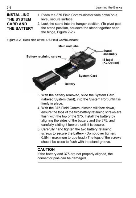
Figure 2-2. Back side of the <strong>375</strong> <strong>Field</strong> <strong>Communicator</strong><br />
Battery retaining screws<br />
Main unit label<br />
Battery<br />
System Card<br />
Stand<br />
assembly<br />
IS label<br />
(KL Option)<br />
3. With the battery removed, slide the System Card<br />
(labeled System Card), into the System Port until it is<br />
firmly in place.<br />
4. With the <strong>375</strong> <strong>Field</strong> <strong>Communicator</strong> still face down,<br />
ensure the tops of the two battery retaining screws are<br />
flush with the top of the <strong>375</strong>. Install the battery by<br />
aligning the sides of the battery and the <strong>375</strong>, and<br />
carefully sliding it forward until it is secure.<br />
5. Carefully hand tighten the two battery retaining<br />
screws to secure the battery. (Do not over tighten,<br />
0.5Nm maximum torque load.) The tops of the screws<br />
should be close to flush with the stand groove.<br />
CAUTION<br />
If the battery and <strong>375</strong> are not properly aligned, the<br />
connector pins can be damaged.


