

Integrated Five-Scene Preset Dimming System - Smarthome
Integrated Five-Scene Preset Dimming System - Smarthome
Integrated Five-Scene Preset Dimming System - Smarthome

You also want an ePaper? Increase the reach of your titles
YUMPU automatically turns print PDFs into web optimized ePapers that Google loves.
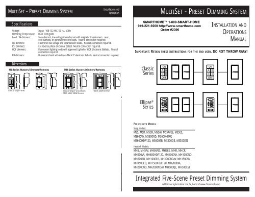
MULTISET - PRESET DIMMING SYSTEM<br />
1.7"<br />
ON<br />
A B<br />
C D<br />
OFF<br />
Specifications<br />
3 YEAR LIMITED WARRANTY<br />
Lightolier Controls warrants that this product will be free from defects in workmanship or materials. This warranty is void<br />
on any electronic controls which have been overloaded, abused, improperly installed or altered in any manner. Lightolier<br />
Controls’ sole obligation will be at its option to repair or replace any electronic controls product proven defective if it is<br />
returned postage-prepaid within three years of the date of shipment from Lightolier Controls to:<br />
Lightolier Controls • 2413 S. Shiloh Road • Garland, Texas 75041<br />
Lightolier Controls will not pay for any charge-back, or charge for labor on material that does not have its previous written<br />
approval. This warranty shall be in lieu of any other warranty — expressed or implied — including, but not limited to, any<br />
implied warranty of merchantability or fitness for a particular purpose. Some states do not allow limitations on how long<br />
an implied warranty lasts and do not allow the exclusion or limitation of incidental or consequential damages. Therefore,<br />
the above limitation or exclusion may not apply to you. This warranty gives you specific legal rights, and you may also have<br />
other rights which vary from state to state.<br />
Exchange of products covered by warranty should be handled through your original supply source.<br />
Lightolier ® Controls<br />
A Genlyte Thomas Company<br />
2413 S. Shiloh Road • Garland, Texas 75041<br />
Installation and<br />
Operation<br />
Voltage: Input: 108-132 VAC, 60 Hz, ±3Hz<br />
Operating Temperature: 0-40˚ Centigrade<br />
Load: VA dimmers: Incandescent, low voltage incandescent with magnetic transformers, neon,<br />
cold cathode, or general inductive loads. Neutral connection required.<br />
QE dimmers: Electronic low voltage and incandescent loads. Neutral connection required.<br />
ESI dimmers: ESI reverse phase electronic ballast. Neutral connection required.<br />
HDF dimmers: Fluorescent lighting loads with approved Lightolier HDF Electronic Ballasts. Neutral<br />
connection required.<br />
EB dimmers: Fluorescent loads with Advance Mark X ® electronic ballasts. Neutral connection required.<br />
Dimensions<br />
MS-Series Masters/Dimmers/Remotes MH-Series Masters/Dimmers/Remotes<br />
3.25"<br />
4.0"<br />
1.2"<br />
1.68"<br />
3.25"<br />
4.0"<br />
This product may be covered by one or more of the following U.S. Patents: #4,413,211; 4,430,576; 4,465,956; 4,733,138; ,792,731; 4,880,950;<br />
4,988,840; 4,992,709; 5,128,654; 5,153,816; 5,189,259; 5,194,858; 5,371,439; 5,371,444; 5,636,111; 5,642,104; 5,646,490; 5,920,156;<br />
Des. 307,578; Des. 333,124; License 4,482,844 and corresponding foreign patents. Other Utility, Design and Foreign Patents Pending.<br />
We reserve the right to change details of design, materials and finish, in any way that will not alter installed appearance or<br />
reduce function performance.<br />
2.61"<br />
0.50"<br />
3.25"<br />
4.50"<br />
Classic or Ellipse ® Series Classic or Ellipse ® Series Masters<br />
500W, 600W, 1000W Dimmers<br />
0.37"<br />
1.37"<br />
1.2"<br />
4.36"<br />
0.50"<br />
3.25"<br />
4.50"<br />
1500W, 2000W Dimmers<br />
1.2"<br />
For technical/sales assistance call:<br />
1-800-526-2731<br />
Made in U.S.A. ©Lightolier Controls 1999<br />
www.lolcontrols.com P/N 85-1042B<br />
FOR USE WITH MODELS:<br />
MULTISET - PRESET DIMMING SYSTEM<br />
ON<br />
A B<br />
C D<br />
OFF<br />
Strap Models:<br />
MS5, MSR, MSCR, MS5AV, MS5AVES, MS5ES,<br />
MS600VA, MS600ND, MS600NDAV,<br />
MS600HDF120, MS600EB, MS300QE, MS300ESI<br />
Heatsink Models:<br />
MH5, MH5AV, MH5AVES, MH5ES, MHR, MHCR,<br />
MH600VA, MH600HDF120, MH1000VA, MH1000ND,<br />
MH600EB, MH1000EB, MH1000NDAV, MH1500VA,<br />
MH1500EB, MH1500HDF120, MH2000VA,<br />
MH2000ND, MH2000NDAV, MH500QE, MH500ESI<br />
ON<br />
A B<br />
C D<br />
OFF<br />
INSTALLATION AND<br />
OPERATIONS<br />
MANUAL<br />
IMPORTANT: RETAIN THESE INSTRUCTIONS FOR THE END USER. DO NOT THROW AWAY!<br />
Classic<br />
Series<br />
Ellipse ®<br />
Series<br />
<strong>Integrated</strong> <strong>Five</strong>-<strong>Scene</strong> <strong>Preset</strong> <strong>Dimming</strong> <strong>System</strong><br />
Additional information can be found at www.lolcontrols.com
2<br />
MULTISET - PRESET DIMMING SYSTEM<br />
Description<br />
MultiSet is a revolutionary system comprised of advanced digital wall box dimmers which are designed for<br />
economical and flexible multi-scene, multi-channel control. MultiSet provides flexible five-scene preset dimming<br />
control for up to 30 wall box dimmers and masters, utilizing standard three-way wiring techniques.<br />
Wiring<br />
MultiSet utilizes standard 3-wire + ground wiring techniques. See wiring diagrams at the back of this booklet.<br />
Caution<br />
Caution: Be sure that power to the load being controlled has been disconnected by removing fuse or turning<br />
circuit breaker off. Installing MultiSet dimmers or Masters with power on may expose you to dangerous<br />
voltage and damage the device.<br />
Read Before Beginning Installation<br />
1. All MultiSet devices require a neutral connection (no common neutrals). Each circuit feeding dimmers<br />
and dimmed loads requires a separate neutral. Shared neutrals will result in undesirable flashing of<br />
controlled loads.<br />
2. Use Quiet Electronic (QE) dimmers to control only low-voltage fixtures that have electronic, solid-state<br />
transformers and regular incandescent loads.<br />
3. Use HDF Direct drive dimmers to control fluorescent lighting loads at 120V with approved Lightolier HDF<br />
Electronic Ballasts only.<br />
4. Use Electronic Ballast (EB) Direct Drive Dimmers to control Advance Mark X ® Dimmable Electronic Ballast.<br />
5. Use Energy Savings Inc. (ESI) to control ESI DIM-E Electronic Ballast.<br />
6. 120 volt MultiSet Strap Dimmers (MS), Masters, Switches, and Remotes mount individually or ganged<br />
together and are supplied without faceplates. They accept Lightolier Controls single and multi-gang Compli<br />
Faceplates or standard decorator-style faceplates by others. Faceplates are not provided.<br />
7. MultiSet Heatsink (MH) Dimmers, Masters, Switches, and Remotes incorporate low-profile heatsinks and<br />
are supplied with coordinating, beveled-edge faceplates. They mount side-by-side with no fins broken and do<br />
not need to be derated. They cannot be ganged with Strap devices. When mounting devices with one or both<br />
fins removed, it is necessary to derate the maximum load of the devices, however, this is not recommended.<br />
Refer to derating chart on page 14.<br />
8. MultiSet Dimmers or Switches may be fed individually or in groups, regardless of phase.<br />
9. MultiSet Masters draw approximately one watt and may be fed from any circuit. Multiple masters<br />
may be inter-connected. The total number of dimmers and masters are not to exceed 30. An unlimited number<br />
of channel remotes (MSCR) may be used.<br />
10. Dimmers can be connected to DA or HDF interface and amplifiers. Please consult interface and<br />
amplifier instructions for wiring. Non-dim switches can be connected to MultiSet relay modules for 277V loads.<br />
11. Line voltage must not be supplied by a GFI breaker.<br />
Installation Instructions<br />
MULTISET DIMMERS AND SWITCHES:<br />
Installation and<br />
Operation<br />
1. Before installation, disconnect power to the circuit by removing the fuse or turning the circuit breaker to the<br />
off position.<br />
2. If you’re replacing an existing device with a MultiSet dimmer or remote:<br />
- Remove the faceplate from the existing device.<br />
- Unscrew and remove the device from the wall box.<br />
- Disconnect all wires from the device.<br />
- Using a voltage tester, identify and mark each of the “hot” and “load” wires connected to the device.<br />
3. If using a Compli screwless faceplate (sold separately), before connecting any wires, be sure the faceplate<br />
mounting adapter plate is behind the device, with the alignment tabs facing forward. The tabs should rest<br />
within the centering holes of the aluminum mounting strap.<br />
4. Be sure the MultiSet dimmer or switch is in the “<strong>System</strong> Off” position. If it is not, press the bottom of device<br />
firmly until it snaps into place. Doing so will cause the “<strong>System</strong> Off” label at the top of device to become<br />
exposed.<br />
5. Connect the MultiSet dimmer or switch wires to the wall box wires as follows:<br />
- Black to “Hot” (120V AC source)<br />
- White to “Neutral”*<br />
- Red to “Load” (light fixture)<br />
- Yellow to “Remote” (MSCR/M4CR)** Cap yellow if MSCR or M4CR is not used.<br />
- Purple to “Network Connection” (line voltage Class 1)***<br />
6. Be sure the ground wire (bare stranded) is connected to earth ground. (NOTE: Mis-wiring or failure to<br />
connect ground may result in improper operation of the device).<br />
7. Ensure all wire connections are tight and that no bare copper is exposed.<br />
8. Install the device into the wall box, making sure all wires are neatly installed. Using the enclosed mounting<br />
screws, secure the device into the wall box.<br />
9. Install the faceplate.<br />
Wire nuts<br />
Dimmer or<br />
Non-Dim Switch<br />
* The white wire must be connected to the neutral wire in the wall box. Failure to do so will result in improper<br />
operation.<br />
** Consult MSCR/MC4 instructions for proper wiring information.<br />
*** Link all MultiSet devices using one line voltage wire connected between each purple wire. Connected devices<br />
will operate as a system.<br />
Black<br />
White<br />
Red<br />
Yellow<br />
Purple<br />
Hot<br />
Neutral<br />
Load<br />
Remote<br />
Network<br />
Provided<br />
Ground Strap Ground Wire<br />
3
4<br />
MULTISET - PRESET DIMMING SYSTEM<br />
Installation Instructions<br />
MULTISET MASTER<br />
MS5(AV), MS5(AV)ES, MH5(AV) AND MH5(AV)ES<br />
1. Caution: Be sure that power is disconnected to avoid damage to unit and shock hazard to installer.<br />
2. If using Compli screwless faceplate (sold separately), before connecting any wires, be sure that the Compli<br />
faceplate mounting adapter plate is behind the device with alignment tabs facing forward. Tabs should rest<br />
within centering holes of mounting strap.<br />
3. Connect the MultiSet Master wires to the Wallbox wires as follows (Figure B):<br />
A. Black to Hot (120V AC Source)<br />
B. White to Neutral*<br />
C. Purple to Network Connection (Line Voltage Class 1)***<br />
4. Be sure the Ground wire (Green) is connected to earth ground. Note: Failure to connect ground properly<br />
may result in improper operation or damage to unit.<br />
Note: Ellipse ® Series strap masters do not have a ground wire. Ellipse ® Series heatsink masters have a bare<br />
wire, which must be connected to ground.<br />
5. For the AV Masters, see the chart (Figure C) for wiring to other devices.<br />
6. Ensure all wire connections are tight and no bare copper is exposed.<br />
7. Install device into wallbox, making sure that all wires are neatly installed into wallbox. Using mounting<br />
screws provided, secure Master into wallbox.<br />
8. Install faceplate.<br />
Figure B<br />
Wire nuts<br />
* The White wire must be connected to the neutral wire in the wallbox. Failure to connect the White wire to the<br />
neutral will result in improper operation.<br />
*** Link all MultiSet devices using one line-voltage wire connected between each purple wire. In turn, connected<br />
wires will operate as a system.<br />
Black<br />
White<br />
Purple<br />
Master<br />
Shown in Classic Series<br />
Hot<br />
Neutral<br />
Network<br />
Green/Bare Ground<br />
Low-Voltage Wire (Momentary Dry Contact) Identification<br />
Ellipse<br />
Infrared<br />
Receiver<br />
(Wall)<br />
CLM-IRW<br />
Terminal<br />
Strip #<br />
1<br />
2<br />
3<br />
4<br />
5<br />
6<br />
7<br />
8<br />
N/A<br />
N/A<br />
®<br />
Classic<br />
Series<br />
5-<strong>Scene</strong><br />
Master<br />
Series<br />
5-<strong>Scene</strong><br />
Master<br />
Infrared<br />
Receiver<br />
(Ceiling)<br />
Occupancy<br />
Sensor<br />
Interface<br />
Interface<br />
6-Button<br />
Designer<br />
Remote<br />
Radio Frequency<br />
Key Chain Transmitter/<br />
Transmitter/ Receiver<br />
Receiver (5-button)<br />
Radio Frequency<br />
Transmitter/<br />
Receiver<br />
(13-button)<br />
MS5AV<br />
MH5AV<br />
MS5AVES<br />
MH5AVES<br />
CLM-IRC CSOSLV OSPS-SYS LMDR5CH B-Key CLMWRCO5 CLMWRC13<br />
Wire Color/<br />
Function<br />
Wire Color/<br />
Function<br />
Wire<br />
Color<br />
Terminal<br />
Strip #<br />
Terminal<br />
Strip #/Color<br />
Terminal<br />
Strip #<br />
Terminal<br />
Strip #<br />
Output #/<br />
Relay Terminal<br />
Output #/<br />
Relay Terminal<br />
Brown<br />
Button Common<br />
Brown<br />
Button Common<br />
Brown 1 8-Green 14<br />
3<br />
1–5, 8<br />
Common<br />
1–5, 8<br />
Common<br />
Red<br />
On Button<br />
Red<br />
On Button<br />
Red 4 16-Orange 12<br />
1<br />
1<br />
Output<br />
1<br />
Output<br />
Orange<br />
A Button<br />
Orange<br />
A Button<br />
Orange N/A N/A 10 N/A<br />
2<br />
Output<br />
2<br />
Output<br />
Yellow<br />
B Button<br />
Yellow<br />
B Button<br />
Yellow N/A N/A 8 N/A<br />
3<br />
Output<br />
3<br />
Output<br />
Green<br />
C Button<br />
Green<br />
C Button<br />
Green N/A N/A 6 N/A<br />
4<br />
Output<br />
4<br />
Output<br />
Blue<br />
D Button<br />
Blue<br />
D Button<br />
Blue N/A N/A 4 N/A<br />
5<br />
Output<br />
5<br />
Output<br />
White w/Violet Stripe White w/Violet Stripe<br />
Off Button Off Button<br />
Violet 2 11-Blue 2<br />
2<br />
8<br />
Output<br />
8<br />
Output<br />
Grey<br />
+5V<br />
Grey<br />
+5V<br />
Grey 3 N/A N/A N/A<br />
N/A<br />
N/A<br />
N/A White w/Red Stripe<br />
Raise Button<br />
N/A N/A N/A N/A N/A<br />
N/A<br />
N/A<br />
N/A White w/Green Stripe<br />
Lower Button<br />
N/A N/A N/A N/A N/A<br />
N/A<br />
N/A<br />
NOTES:<br />
1) B-Key must use a step down transformer (12-volt) unless wired to the BCC.<br />
2) OSPS-SYS for use with OSC or OSW sensors. All loads controlled by dimmer.<br />
3) To activate a button function from the low-voltage wiring, a simple momentary closure (contact) is<br />
required. This wiring connection must be from the button control wire (ex: red wire for the ON button)<br />
to the button common wire (brown). To ensure reliable operation, this closure should be of the dry<br />
contact type.<br />
4) For buttons A–L, the closure duration should be between 50 and 300 milliseconds. On Ellipse ® Series<br />
Masters (ex: MS5AVES), the ON and OFF button closures should be between 50 and 300 milliseconds.<br />
The RAISE and LOWER button closures must be at least 50 milliseconds. On Classic series masters<br />
(ex: MS5AV), the ON and OFF button closures must be at least 50 milliseconds.<br />
5) The +5V wire (grey) should only be connected to the devices shown in the table above. Connecting this<br />
wire to any other device may damage the master.<br />
6) Cap off any unused (N/A) wires.<br />
Mounting Options<br />
Individual Mounts<br />
Ganged Mounting<br />
(600W Max per<br />
dimming switch)<br />
120VAC<br />
Line<br />
120VAC<br />
Line<br />
Remote<br />
MSR<br />
ON<br />
OFF<br />
Remote<br />
MSR<br />
ON<br />
OFF<br />
120VAC<br />
Line<br />
120VAC<br />
Line<br />
Remote<br />
MS-5<br />
ON<br />
A B<br />
C D<br />
OFF<br />
Remote<br />
MS-5<br />
ON<br />
A B<br />
C D<br />
OFF<br />
Figure C<br />
120VAC<br />
Line<br />
120VAC<br />
Line<br />
Master<br />
MS-5<br />
ON<br />
A B<br />
C D<br />
OFF<br />
Master<br />
MS-5<br />
ON<br />
A B<br />
C D<br />
OFF<br />
Line<br />
120VAC<br />
MS600VA<br />
Line<br />
120VAC<br />
MS600VA<br />
Line<br />
120VAC<br />
Installation and<br />
Operation<br />
To Load To Load To Load To Load<br />
To Loads<br />
MS600VA<br />
* Wire appropriate number of circuits to accommodate load, no common neutrals.<br />
Line<br />
120VAC<br />
(7) MS600VA*<br />
MS600VA<br />
5
6<br />
MULTISET - PRESET DIMMING SYSTEM<br />
Replacing the Keypad Button Labels (Classic Series)<br />
MultiSet Classic Series Masters are supplied with over 260<br />
labels to personalize the buttons for your own scene names.<br />
The buttons are labeled at the factory with letters. These<br />
button labels can easily be changed to customize your system:<br />
1. Insert a small screwdriver into the outside edge on<br />
the side of a button and pry off the plastic key cover.<br />
Caution: Pry from outside edge, do not attempt to<br />
insert screwdriver between key covers. (Figure D)<br />
2. Remove the factory label and insert an appropriate<br />
label from the supplied label sheet into the key cover.<br />
3. Snap the cover over the button housing by pressing<br />
firmly on the plastic key cover.<br />
4. Repeat for each button you wish to change.<br />
Figure D<br />
ON<br />
A B<br />
Replacing the Keypad Membrane (Ellipse ® Series)<br />
The overlay on these models is easily replaced, even if the unit<br />
is currently installed.<br />
1. Turn the power off at the circuit breaker.<br />
2. Remove the faceplate (Figure E).<br />
3. Remove the master keypad wall screws (Figure F).<br />
3a. On heatsink model, remove heatsink screws and spacers<br />
(Figure F).<br />
4. Remove the retaining plate screws and plate (Figure G).<br />
5. Remove the existing keypad membrane.<br />
6. Install the new keypad membrane, being careful to line it<br />
up properly with the openings.<br />
7. Reinstall the retaining plate and screws (Figure G).<br />
7a. On heatsink model, reinstall screws and spacers<br />
(Figure F).<br />
8. Reinstall the master keypad to wallbox (Figure F).<br />
9. Reinstall the faceplate (Figure E).<br />
10. Turn the power back on at the circuit breaker.<br />
Note: Spacers on the heatsink model are not attached<br />
to the unit.<br />
Heatsink<br />
Screws<br />
Wall<br />
Screws<br />
Faceplate<br />
Figure E<br />
Figure F Figure G<br />
Screws<br />
Dimmer/Switch Operating Instructions<br />
MULTISET DIMMER<br />
• To turn light on to preset level, tap top of rocker, the dimmer will fade up at the 1.5 second rate.<br />
• A second tap of the rocker fades the dimmer to full brightness.<br />
• To adjust the light level, press and hold top or bottom of rocker until<br />
desired light level is reached, and then release.<br />
• To turn lights off tap the bottom of the rocker. The dimmer will fade<br />
at the 3 second fade rate.<br />
• To quickly return to the preset level when light is on, quickly tap OFF<br />
and then ON. The lights will then adjust to the preset level.<br />
• To bypass the fade rate and turn the lights to full ON or OFF, double<br />
tap the dimmer for ON or OFF.<br />
• If the master is in the OFF scene, the master ON button will illuminate<br />
when any dimmer is turned on.<br />
• To change the preset level of the current scene:<br />
• Press and hold the rocker until lights reach the desired level<br />
then release<br />
• Press the small set button next to the switch to save the<br />
preset in memory<br />
LEDs on the MultiSet Dimmer/Switch indicate status:<br />
1. Red LED is on when Dimmer/Switch is off to locate Dimmer/<br />
Switch when room is dark<br />
2. As many as 3 green LEDs may be illuminated at any given time.<br />
The bright green LED indicates the current level of the dimmer.<br />
The medium green LED indicates the preset level of the current<br />
scene. The dim green LED indicates the preset level of the<br />
ON scene.<br />
MULTISET UNIVERSAL ELECTRONIC SWITCH (NON-DIM)<br />
Programming <strong>Scene</strong>s<br />
After installation of all MultiSet devices is completed and the system<br />
has been energized, programming of each scene can be performed.<br />
Programming is as simple as 1–2–3.<br />
1. Tap the Master preset button you wish to program<br />
(i.e., ON, A, B, C or D). (See Step 1)<br />
2. Adjust each MultiSet dimmer to the desired intensity<br />
and/or the switches to either on or off. (See Step 2, pg.8)<br />
3. After all devices have been adjusted, press the<br />
“Set” button on each unit. (See Step 3, pg.8)<br />
4. Repeat steps 1-3 until all scenes have been programmed.<br />
Note: Dimmers cannot be programmed off for the “ON” preset.<br />
Non-dim switches may be programmed “OFF”, see page<br />
8 for details.<br />
Ellipse ® Series<br />
Master<br />
Step 1<br />
Classic Series<br />
Master<br />
Installation and<br />
Operation<br />
Red LED<br />
Green LED<br />
Set<br />
Button<br />
The MultiSet Universal programmable switch can be programmed as a four or five-scene non-dim switch. When<br />
programmed as a five-scene device, it is not suitable for 3-way applications.<br />
The default mode of the switch is as a normal (4-scene) non-dim device. The AV (5-scene) mode allows the non-dim<br />
switch to remain off when the master ON button is pressed.<br />
To change the mode of the switch:<br />
1. Tap OFF on the Master to place the switch in the OFF scene.<br />
2. Press and hold the set button (See Step2, pg.8). After 3 Seconds, a green LED will illuminate on the bargraph.<br />
If the switch is currently in normal mode, the bottom green LED will illuminate. If it is in AV mode, the top<br />
LED will illuminate.<br />
3. Tap the top of the rocker once to toggle the mode.<br />
4. Release the set button.<br />
Note: In normal mode, a “soft start” feature is utilized to extend bulb life. In AV mode, the “soft start” feature is<br />
not implemented.<br />
<strong>Preset</strong><br />
Buttons<br />
(On, A, B, C, D)<br />
7
8<br />
MULTISET - PRESET DIMMING SYSTEM<br />
Changing the Fade Rate<br />
1. NOTE: MultiSet dimmers can be programmed for<br />
either a 3- or 15-second fade rate. To change the<br />
fade rate:<br />
- Press the “Off” button on the MultiSet Master.<br />
- While holding the “Set” button in (See Step 3),<br />
tap the top of rocker once. As the process is<br />
repeated, the unit will toggle between fade rates.<br />
2. Repeat this process for each dimmer you want<br />
to change.<br />
All dimmers are shipped from the factory with a 3 second<br />
fade rate.<br />
IR Receiver Programming<br />
Step 2<br />
Press and<br />
hold Top/Bottom<br />
to Raise/Lower<br />
Intensity<br />
Setting the Button Brightness (Ellipse ® Series)<br />
Each Ellipse ® Master Control Station button brightness can be programmed for 100%<br />
(factory default), 75%, 50%, or 25% brightness. To change the setting follow the<br />
instructions below:<br />
1. On the master, press and hold buttons “B” and “D” simultaneously for 3 seconds.<br />
Buttons “A” thru “D” will illuminate. The blinking LED displays the current LED<br />
brightness setting. The continuously-illuminated LEDs display the available<br />
brightness settings that can be selected.<br />
2. To change the brightness setting, press the button illuminated (A, B, C or D) at<br />
the desired brightness. This button will begin blinking.<br />
3. To save the selected brightness and exit the mode, press the ON button. All<br />
buttons on that master will now have the same new brightness settings.<br />
Ellipse ® masters with IR receivers can be programmed to operate in one of<br />
four IR modes, plus OFF. This allows up to four Master Control Stations to<br />
be installed in close proximity to each other, but each controlling separate<br />
MultiSet systems. The Master Control Stations are factory–programmed to<br />
OFF. To change the programming, follow the instructions below:<br />
1. On the master, press and hold buttons A and C simultaneously<br />
for 3 seconds.<br />
2. The current room programmed will blink on the master A,B,C,D or<br />
OFF (factory default).<br />
3. Press the room button that you want to program [RM 1(A), RM 2(B),<br />
RM 3(C) or RM 4(D),OFF]. The button pressed will begin blinking.<br />
4. Press the ON button to save the selected room (or OFF) and exit the<br />
programming mode.<br />
(Note: factory default is OFF).<br />
Press room button that<br />
you want to program<br />
(RM 1, RM 2, RM 3, RM 4,<br />
OFF); button begins blinking.<br />
Set Button<br />
Button LED<br />
Brightness<br />
A 100%<br />
B 75%<br />
C 50%<br />
D 25%<br />
Step 3<br />
Button<br />
A<br />
B<br />
C<br />
D<br />
Controlling MS5ES / MH5ES from Remote Control Units<br />
Installation and<br />
Operation<br />
CLMIRT This remote control transmitter always operates in ROOM 1 mode. Therefore, the master must be in<br />
ROOM 1 mode to receive commands from the remote control.<br />
CLMIRTES This remote control transmitter can operate in all four ROOM modes. On the transmitter, you must<br />
first press a ROOM button to place the transmitter in that mode. (example: pressing ROOM 2 sets<br />
the transmitter in ROOM 2 mode). The transmitter will then control any Master Control Station<br />
programmed to receive that same rooms commands.<br />
Operating Instructions<br />
MULTISET MASTER (CLASSIC SERIES)<br />
• Tap the ON button to elegantly illuminate the entire area to<br />
the ON "preset".<br />
• Press and hold the ON button to brighten lighting level.<br />
• Tap the OFF button to fade lights to OFF.<br />
• Press and hold OFF button to lower lighting level.<br />
• Tap a scene button to access "preset" light levels.<br />
(ON/OFF Master does not have this feature)<br />
• Two Quick taps of any button (including ON and OFF) will<br />
fade lighting quickly.<br />
MULTISET MASTER (ELLIPSE ® SERIES)<br />
• Press or Tap the ON button to elegantly illuminate the entire area<br />
to the ON "preset".<br />
• Press the RAISE button to brighten lighting level.<br />
• Tap the OFF button to fade lights to OFF.<br />
• Press LOWER button to lower lighting level.<br />
• Tap a scene button to access one of the "preset" light levels.<br />
• Two quick taps of any button (except RAISE or LOWER) will fade<br />
lighting quickly.<br />
• For information on the IR Receiver, see Infrared Receiver below.<br />
Infrared Receiver<br />
OFF<br />
A<br />
B<br />
C<br />
D<br />
Raise/Lower<br />
Button<br />
Built-in IR<br />
Receiver<br />
Ellipse ® Series 5-<strong>Scene</strong> Masters models have an integrated Infrared (IR) receiver that allows<br />
them to receive IR commands from a remote control unit (CLMIRT, CLMIRTES).<br />
The CLMIRTES infrared transmitter is capable<br />
of operating over an unobstructed range of<br />
approximately 25 feet. Within this range, scenes<br />
can be selected, raised and lowered, and lighting<br />
may be turned On and Off using the handheld<br />
remote transmitter. In addition, the CLMIRTES<br />
is capable of controlling up to 4 different<br />
MultiSet or MultiSet Pro control station groups.<br />
Note: This system is based on line-of-sight operations.<br />
Therefore, the receiver must be able to<br />
“See” the transmitter. Any obstruction between<br />
the transmitter and receiver may adversely affect<br />
the performance of the unit.<br />
See page 8 for additional CLMIRTES information.<br />
CLMIRTES<br />
CLMIRT<br />
ON<br />
MAX<br />
All-On<br />
A B<br />
C D<br />
Off<br />
9
MULTISET - PRESET DIMMING SYSTEM<br />
10<br />
Wiring Diagrams<br />
MS-5<br />
P<br />
B<br />
W<br />
Typical Layout Using High Wattage Dimmers with Masters<br />
(Masters mounted remotely)<br />
MS-5<br />
P<br />
B<br />
W<br />
MS-5<br />
B<br />
W<br />
MS-5<br />
P P<br />
W<br />
B<br />
Hall Lights<br />
500 Watts<br />
To Load<br />
R<br />
R<br />
MH600VA MH1500VA<br />
Yellow<br />
B W<br />
Foyer Lights<br />
1100 Watts<br />
To Load<br />
B W<br />
Chandelier<br />
1500 Watts<br />
To Load<br />
L N<br />
120VAC<br />
L N<br />
120VAC<br />
P P<br />
P<br />
MultiSet AV Master (MS5AV)<br />
R<br />
MH2000VA<br />
MSCR<br />
Y<br />
Y Y<br />
W<br />
G<br />
B B<br />
L N<br />
120VAC<br />
MS5AV<br />
CLM-IRW<br />
White<br />
Black<br />
N L<br />
120VAC<br />
Purple<br />
Brown<br />
Red<br />
Orange<br />
Yellow<br />
Green<br />
Blue<br />
White w/Violet Stripe<br />
Grey<br />
See page 5 Figure C<br />
•<br />
•<br />
•<br />
•<br />
•<br />
•<br />
•<br />
•<br />
1<br />
2<br />
3<br />
4<br />
5<br />
6<br />
7<br />
8<br />
GND<br />
Wiring Notes: No common neutrals may be used between dimmed circuits of unlike phases.<br />
Purple wire is a line voltage carrier, observe wiring codes.<br />
Line voltage must not be supplied by a GFI breaker.<br />
Wire<br />
W<br />
B<br />
P<br />
R<br />
Y<br />
G<br />
Color Code<br />
White<br />
Black<br />
Purple<br />
Red<br />
Yellow<br />
Grey<br />
L N<br />
120VAC<br />
B<br />
W<br />
MS5<br />
B W P P W B<br />
L N<br />
120 VAC<br />
Any Phase<br />
Master<br />
MS5ES<br />
P<br />
<strong>Dimming</strong> Amplifier (DA22000VAI)<br />
MS600VA<br />
MS600VA<br />
To<br />
Load<br />
B<br />
W<br />
120VAC<br />
R<br />
Y<br />
R<br />
Y<br />
MS<br />
Dimmer<br />
MS600HDF120<br />
W<br />
L N<br />
120VAC<br />
P P<br />
DA22000VAI<br />
Dual 2kW<br />
Amplifier<br />
L N L N<br />
120 VAC 120 VAC<br />
Same Phase<br />
Direct Drive Fluorescent <strong>Dimming</strong> (HDF Dimmer)<br />
W<br />
R<br />
R<br />
T<br />
W<br />
B<br />
T<br />
W<br />
PowerSpec<br />
HDF Ballast<br />
Wiring Notes: No common neutrals may be used between dimmed circuits of unlike phases.<br />
Purple wire is a line voltage carrier, observe wiring codes.<br />
Line voltage must not be supplied by a GFI breaker.<br />
Y<br />
B<br />
Y<br />
Wire<br />
W<br />
B<br />
P<br />
R<br />
Wire<br />
W<br />
B<br />
P<br />
R<br />
T<br />
Installation and<br />
Operation<br />
To Load 1<br />
To Load 2<br />
Color Code<br />
White<br />
Black<br />
Purple<br />
Red<br />
Color Code<br />
White<br />
Black<br />
Purple<br />
Red<br />
Tan<br />
To Lamps<br />
11
MULTISET - PRESET DIMMING SYSTEM<br />
12<br />
L N<br />
120VAC<br />
B<br />
W<br />
Wire<br />
W<br />
B<br />
P<br />
R<br />
Sympton<br />
Master<br />
MS5ES<br />
Lamps do not start, flicker<br />
or go out at low-level<br />
One lamp end repeatedly<br />
blackens prematurely<br />
Cannot resolve problem<br />
Direct Drive Fluorescent <strong>Dimming</strong> (EB Dimmer)<br />
MS600EB<br />
L N<br />
W<br />
P<br />
120VAC<br />
P<br />
Color Code<br />
White<br />
Black<br />
Purple<br />
Red<br />
Troubleshooting Guide<br />
B<br />
Possible Solution<br />
• Linear lamps are particularly sensitive to the correct<br />
grounding of the ballast to the fixture. Verify proper<br />
ground wire installation.<br />
• Control device minimum set point adjusted too low.<br />
Try raising slightly.<br />
• Lamps not seated properly in lamp sockets.<br />
Reseat lamps.<br />
• To insure control is operating properly, connect an<br />
incandescent lamp load across the red dimming wire<br />
and white neutral wire at the wallbox. Control should<br />
dim the lamp properly.<br />
• Possible loose, shorted or broken wires between<br />
lamp and ballast. Verify wiring is correct and not<br />
damaged.<br />
• Call Advance at (800) 372-3331 and ask for<br />
applications support.<br />
R<br />
W<br />
Y<br />
B<br />
W<br />
Advance<br />
Mark X ® Ballast<br />
Total Ballast Quantity<br />
Lamp<br />
Watts<br />
26<br />
32<br />
42<br />
26<br />
40<br />
40<br />
25<br />
25<br />
25<br />
32<br />
32<br />
32<br />
Type<br />
Lamp<br />
T4<br />
T4<br />
T4<br />
T4<br />
T5<br />
T5<br />
T8<br />
T8<br />
T8<br />
T8<br />
T8<br />
T8<br />
Ballast<br />
Model<br />
REZ–IT32<br />
REZ–IT32<br />
REZ–IT42<br />
REZ–2Q26<br />
REZ–ITT540<br />
REZ–2TT540<br />
REZ–132<br />
REZ–2532<br />
REZ–3532<br />
REZ–132<br />
REZ–2532<br />
REZ–3532<br />
Wiring Notes: No common neutrals may be used between dimmed circuits of unlike phases.<br />
Purple wire is a line voltage carrier, observe wiring codes.<br />
Line voltage must not be supplied by a GFI breaker.<br />
To Lamps<br />
No. of<br />
Ballast<br />
19<br />
35<br />
48<br />
15<br />
25<br />
39<br />
12<br />
20<br />
30<br />
10<br />
17<br />
26<br />
15<br />
24<br />
36<br />
7<br />
12<br />
18<br />
19<br />
35<br />
48<br />
10<br />
16<br />
25<br />
6<br />
11<br />
16<br />
15<br />
25<br />
41<br />
8<br />
13<br />
20<br />
5<br />
9<br />
14<br />
Lightolier<br />
Dimmer Model<br />
MS600EB<br />
MH1000EB<br />
MH1500EB<br />
MS600EB<br />
MH1000EB<br />
MH1500EB<br />
MS600EB<br />
MH1000EB<br />
MH1500EB<br />
MS600EB<br />
MH1000EB<br />
MH1500EB<br />
MS600EB<br />
MH1000EB<br />
MH1500EB<br />
MS600EB<br />
MH1000EB<br />
MH1500EB<br />
MS600EB<br />
MH1000EB<br />
MH1500EB<br />
MS600EB<br />
MH1000EB<br />
MH1500EB<br />
MS600EB<br />
MH1000EB<br />
MH1500EB<br />
MS600EB<br />
MH1000EB<br />
MH1500EB<br />
MS600EB<br />
MH1000EB<br />
MH1500EB<br />
MS600EB<br />
MH1000EB<br />
MH1500EB<br />
L N<br />
120VAC<br />
Wire<br />
W<br />
B<br />
P<br />
R<br />
B<br />
W<br />
Master<br />
MS5ES<br />
Color Code<br />
White<br />
Black<br />
Purple<br />
Red<br />
Direct Drive Fluorescent <strong>Dimming</strong> (ESI Dimmer)<br />
MS300ESI<br />
W<br />
L N<br />
120VAC<br />
P P<br />
B<br />
Total Ballast Quantity<br />
R<br />
W<br />
Y<br />
Model #<br />
Manufacture<br />
MS300ESI<br />
Lightolier Controls<br />
MH500ESI<br />
Lightolier Controls<br />
Sympton<br />
B<br />
W<br />
Control<br />
Wattage<br />
300 Watt<br />
500 Watt<br />
Troubleshooting Guide<br />
Lamps do not start, flicker<br />
or go out at low-level<br />
One lamp end repeatedly<br />
blackens prematurely<br />
Cannot resolve problem<br />
ESI DIM-E<br />
Ballast<br />
Installation and<br />
Operation<br />
Maximum no. of Dim-E ballast for each<br />
control device (# of lamps = # per control)<br />
2L32W = 3; 2L25W = 4<br />
1L40W = 5; 1L32W = 7; 1L25W =9; 1L17W = 13<br />
2L32W = 5; 2L25W = 7<br />
1L40W = 9; 1L32W = 11; 1L25W =15; 1L17W = 22<br />
Possible Solution<br />
Wiring Notes: No common neutrals may be used between dimmed circuits of unlike phases.<br />
Purple wire is a line voltage carrier, observe wiring codes.<br />
Line voltage must not be supplied by a GFI breaker.<br />
To Lamps<br />
• Linear lamps are particularly sensitive to the correct<br />
grounding of the ballast to the fixture. Verify proper<br />
ground wire installation.<br />
• Control device minimum set point adjusted too low.<br />
Try raising slightly.<br />
• Lamps not seated properly in lamp sockets.<br />
Reseat lamps.<br />
• To insure control is operating properly, connect an<br />
incandescent lamp load across the red dimming wire<br />
and white neutral wire at the wallbox. Control should<br />
dim the lamp properly.<br />
• Possible loose, shorted or broken wires between<br />
lamp and ballast. Verify wiring is correct and not<br />
damaged.<br />
• Call Energy Savings, Inc. at 847-925-8400<br />
and ask for applications support.<br />
13
MULTISET - PRESET DIMMING SYSTEM<br />
14<br />
Ganging and Derating<br />
HEATSINK DEVICES<br />
No Fins Broken – Separate Wallboxes<br />
Devices of matching depth can be mounted next to each<br />
other in separate single gang wallboxes. The boxes must<br />
be spaced to the dimensions shown in Figure H. Allow 6”<br />
of clearance above and below the dimmers.<br />
Note: For Precision Dimmers add 1/8” to each horizontal<br />
dimension shown in Figure 1. Faceplate depth: 5/8”.<br />
No Fins Broken – Multi-gang Wallbox<br />
When mounting devices with no fins removed, use Table A<br />
to determine what size multi-gang wallbox is required.<br />
Note:<br />
1. When installing a even number of small devices, only<br />
use wallbox size listed in Table A and space one<br />
additional box 3/4” away from the others.<br />
2. When combining small and large devices, be certain<br />
to position a small device at one end and a large<br />
device at the other end of the multi-gang box.<br />
3. Mount dimmers with heatsink fins aligned vertically.<br />
Fins Broken – Multi-gang Heatsink Wallbox<br />
When mounting devices with fins broken in multi-gang<br />
boxes, follow information in Table B to determine the<br />
correct wallbox size.<br />
Fins Broken – Derating<br />
When mounting devices with one or both fins removed it is<br />
necessary to derate the maximum load of the devices in<br />
accordance with the FINS BROKEN–DERATING CHART in<br />
Table C.<br />
1 5 /16"<br />
Figure H<br />
No Fins Broken-Seperate Wallboxs<br />
2 3/4"<br />
3 5/8" 4 1/2"<br />
2 3 No Fins Broken No Fins Broken<br />
/4"<br />
4 1 /2"<br />
Fins Broken Fins Broken<br />
Table A – No Fins Broken-Multi Gang Wallbox<br />
Number of<br />
Small Devices<br />
0<br />
1<br />
2<br />
3<br />
4<br />
5<br />
6<br />
0<br />
0<br />
1<br />
1+1<br />
4<br />
4+1<br />
7<br />
7+1<br />
Number of Large Devices<br />
1<br />
1<br />
3<br />
5<br />
6<br />
8<br />
9<br />
11<br />
2<br />
4<br />
6<br />
7<br />
9<br />
10<br />
12<br />
13<br />
3<br />
6<br />
8<br />
10<br />
11<br />
13<br />
14<br />
16<br />
4<br />
9<br />
11<br />
12<br />
14<br />
15<br />
17<br />
18<br />
Table B – Fins Broken-Multi-Gang Wallbox<br />
Number of<br />
Small Devices<br />
0<br />
1<br />
2<br />
3<br />
4<br />
5<br />
Number of Large Devices<br />
0 1 2 3 4 5<br />
1 3 5 7 9<br />
1 3 5 7 9 11<br />
2 4 6 8 10 12<br />
3 5 7 9 11 13<br />
4 6 8 10 12 14<br />
5 7 9 11 13 15<br />
Table C – Fins Broken-Derating Chart<br />
Device Max.<br />
Load<br />
500W<br />
600W<br />
1000W<br />
1500W<br />
2000W<br />
3 5 /8"<br />
Wallbox Dimmers–Fins Removed<br />
ONE SIDE<br />
425W<br />
600W<br />
800W<br />
1300W<br />
1800W<br />
BOTH SIDES<br />
350W<br />
500W<br />
700W<br />
1100W<br />
1600W<br />
3 /8"<br />
4 11/16"<br />
Installer’s Notes:<br />
Installation and<br />
Operation<br />
15


