GDO-11v1 User Manual.indd - Dominator
GDO-11v1 User Manual.indd - Dominator
GDO-11v1 User Manual.indd - Dominator

You also want an ePaper? Increase the reach of your titles
YUMPU automatically turns print PDFs into web optimized ePapers that Google loves.
Part # 13246 (<strong>Manual</strong> v1.02)<br />
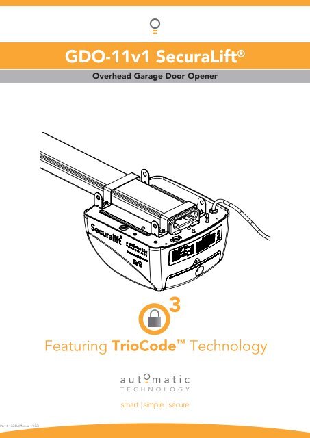
<strong>GDO</strong>-<strong>11v1</strong> SecuraLift ®<br />
Overhead Garage Door Opener<br />
Featuring TrioCode Technology
WARNING: It is vital for the safety of persons to follow<br />
all instructions. Failure to comply with the installation<br />
instructions and the safety warnings may result in serious<br />
personal injury and/or property damage.<br />
Please save these instructions for future reference.<br />
Automatic Technology (Australia) Pty Ltd to the extent that such may be lawfully excluded hereby expressly disclaims all<br />
conditions or warranties, statutory or otherwise which may be implied by laws as conditions or warranties of purchase of an<br />
Automatic Technology (Australia) Pty Ltd Garage Door Opener. Automatic Technology (Australia) Pty Ltd hereby further<br />
expressly excludes all or any liability for any injury, damage, cost, expense or claim whatsoever suffered by any person<br />
as a result whether directly or indirectly from failure to install the Automatic Technology (Australia) Pty Ltd Garage Door<br />
Opener in accordance with these installation instructions.<br />
2 <strong>GDO</strong>-<strong>11v1</strong> SecuraLift® Owner Installation Instructions
<strong>GDO</strong>-<strong>11v1</strong> SecuraLift ®<br />
Overhead Garage Door Opener<br />
Important Safety Instructions 4<br />
Features 6<br />
Operating Controls 8<br />
Kit Contents 10<br />
Installation 11<br />
Knockdown C-Rail Assembly 11<br />
C-Rail Attachment 13<br />
Determine Door Type 14<br />
Mounting - Track Type Door 15<br />
Mounting - Spring Loaded Door 16<br />
Mounting Door Bracket & Arms 17<br />
Programming the Opener 18<br />
Setting Travel Limits - Control Panel 18<br />
Setting Travel Limits - Transmitter 19<br />
Safety Obstruction Forces 20<br />
Safety Obstruction Force Test 20<br />
Adjusting Safety Obstruction Forces 21<br />
Coding Transmitters 22<br />
Door 22<br />
Vacation Mode 22<br />
Auxiliary Out Put 22<br />
Pet Mode 23<br />
Courtesy Light 23<br />
Remotely Coding Transmitters 24<br />
Erasing Transmitter Codes 24<br />
Accessories 25<br />
Photo Electric Beam Installation 25<br />
Key switch 25<br />
Auxiliary output 25<br />
Battery Back Up installation 26<br />
SmartSolar Installation 27<br />
Final Set Up 28<br />
Pet Mode Door Height 28<br />
Wall Mounted Transmitters 28<br />
Re-Initialising 28<br />
Default Settings & Specifi cations 29<br />
Parameters 30<br />
Door Status Indicators 30<br />
Button functions 30<br />
Troubleshooting Guide 31<br />
Maintenance Record 32<br />
Parts Listing 33<br />
Warranty 34<br />
Owner Installation Instructions <strong>GDO</strong>-<strong>11v1</strong> SecuraLift® 3
Important Safety Instructions<br />
WARNING: It is vital for the safety of persons to follow<br />
all instructions. Failure to comply with the following<br />
Safety Rules may result in serious personal injury and/or<br />
property damage.<br />
CAUTION: If your garage has no pedestrian entrance door, an emergency access device should be installed.<br />
This accessory allows manual operation of the garage door from outside in case of power failure.<br />
For ADDITIONAL ENTRAPMENT protection we STRONGLY recommend the fi tting of a Photo Electric<br />
(P.E.) Beam. In most countries P.E. Beams are mandatory on all garage doors fi tted with automatic<br />
openers. For a small additional outlay Automatic Technology recommends that Photo Electric Beams<br />
be installed with the automatic opener ensuring additional safety and peace of mind.<br />
DO NOT operate the opener unless the garage door is in full view and free from objects such<br />
as cars and children/people. Make sure that the door has fi nished moving before entering or<br />
leaving the garage.<br />
DO NOT operate the opener when children/persons are near the door. Children must be<br />
supervised at all times when the SecuraLift® is in use. Serious personal injury and/or<br />
property damage can result from failure to follow this warning.<br />
DO NOT allow children to operate the SecuraLift®. Serious personal injury and/or<br />
property damage can result from failure to follow this warning.<br />
Regularly check to make sure that the safety obstruction force is working<br />
correctly, and is tested and set as per page 20 of this manual. Failure to<br />
follow these instructions could result in serious personal injury and/or<br />
property damage. This test must be repeated at regular intervals and the<br />
necessary adjustments made as required.<br />
Doors requiring over 400N of force to move must have P.E. Beams<br />
installed.<br />
DO NOT disengage the door opener to manual operation with<br />
children/persons or any other objects including motor vehicles<br />
within the doorway.<br />
The door opener is not intended for use by young children<br />
or infi rm persons without adequate supervision. Children<br />
should be supervised to ensure that they do not play<br />
with the remote transmitters or the opener.<br />
Keep hands and loose clothing clear of the door<br />
and door opener at all times.<br />
4 <strong>GDO</strong>-<strong>11v1</strong> SecuraLift® Owner Installation Instructions
Important Safety Instructions<br />
The unit should be installed so that it is protected from the elements. It should not be exposed to water or rain.<br />
It is not to be immersed in water or sprayed directly by a hose or other device.<br />
The garage door must be well balanced. Sticking or binding doors must be repaired by a qualifi ed garage<br />
door installer prior to installation of the opener.<br />
Frequently examine the installation, in particular cables, springs and mountings for signs of wear, damage<br />
or imbalance. DO NOT use if repair or adjustment is needed since a fault in the installation or an<br />
incorrectly balanced door may cause injury. DO NOT attempt to repair the door yourself as hardware<br />
is under extreme tension.<br />
Remove or disengage all garage door locks and mechanisms prior to installation of the opener.<br />
Connect the opener to a properly earthed general purpose 240V mains power outlet installed<br />
by a qualifi ed electrical contractor.<br />
Disconnect the power cord from mains power before making any repairs or removing<br />
covers. Only experienced service personnel should remove covers from the opener.<br />
In order for the SecuraLift® to sense an object obstructing the door way, some force<br />
must be exerted on the object. As a result the object, door and/or person may<br />
suffer damage or injury.<br />
If the power supply cord is damaged, it must be replaced by an Automatic<br />
Technology service agent or suitably qualifi ed person.<br />
Make sure that the door is fully open before driving in or out of the garage<br />
and fully closed before leaving the driveway.<br />
Make sure that remote controls are kept out of reach of children.<br />
Install the (optional) wall switch or (optional) wall mounted<br />
transmitter in a location where the garage door is visible, but<br />
out of the reach of children at a height of at least 1.8 meters<br />
from the fl oor.<br />
Owner Installation Instructions <strong>GDO</strong>-<strong>11v1</strong> SecuraLift® 5
Features<br />
Thank you for purchasing the Automatic Technology<br />
<strong>GDO</strong>-<strong>11v1</strong> SecuraLift ® Overhead Garage Door<br />
Opener. Designed to suit sectional overhead and one<br />
piece tilt up doors, the components and materials<br />
used ensure this opener will provide years of<br />
smart, simple and secure operation. Listed<br />
below are some of the many features:<br />
Operation<br />
To open or close the door simply press a button on a TrioCode handheld<br />
transmitter, or optional wall switch for two seconds. During open and close cycles<br />
the door can be stopped by pressing the button again. The next actuation will<br />
move the door in reverse direction.<br />
TrioCode Code Hopping Technology<br />
Every time a TrioCode transmitter is used a new security code is randomly<br />
generated from over 4.29 billion possibilities. This greatly enhances the security<br />
of the system and makes “code grabbing” a thing of the past<br />
These transmitters also overcome interference issues by simultaneously sending a<br />
signal over three different frequencies. Even if two of the three signals are jammed,<br />
the system will still work.<br />
S-ALPS (Semi Automatic Limits Positioning System)<br />
The S-ALPS system does away with manual adjustment of the door’s limits position<br />
using mechanical parts, such as cams and microswitches. During installation the<br />
handheld transmitter can be programmed to set the limits positions.<br />
ISS (intelligent safety obstruction system)<br />
While the door is performing a close cycle, should it hit an obstacle or be restricted in some<br />
manner, it will automatically reverse. The amount of force the door should encounter before<br />
reversing is automatically adjusted by the doors control system during the initial installation of the<br />
automatic door opener. The door will also stop if restricted whilst opening. The Safety Obstruction<br />
Force should be checked monthly.<br />
Auto courtesy light<br />
The courtesy light comes on automatically for three minutes whenever the door is activated. The light can also<br />
be operated independently of the door by coding a dedicated button on a transmitter.<br />
6 <strong>GDO</strong>-<strong>11v1</strong> SecuraLift® Owner Installation Instructions
SmartSolar and Battery Back Up Compatibility (optional)<br />
The opener can be fi tted with a SmartSolar or Battery Back Up kit for operation in the<br />
event of a power outage, or where mains power access is not available.<br />
NOTE: If the door is the only entrance to the garage, and a battery back up kit is<br />
not fi tted, a keyed cable release should be fi tted external to the garage.<br />
Vacation mode<br />
A hand held transmitter can be programmed to lock and unlock all other<br />
transmitters that have been programmed into the openers’ memory. The vacation<br />
mode can be used when the door is left idle for long periods of time.<br />
Pet/Pedestrian mode<br />
The transmitter can be programmed to open the door to an adjustable partial<br />
height so that the family pet can enter and exit the garage at any time. You may also<br />
wish to open the door to a height suitable only for pedestrian access.<br />
Photo Electric (P.E.) Beam (optional)<br />
The opener has an input to connect a P.E. Beam for extra safety.<br />
<strong>Manual</strong> operation<br />
The opener is equipped with a unique manual disengaging device. If the power to the opener<br />
is disrupted the door can be put into manual mode by pulling down on the string handle on an<br />
angle towards the door. This allows for manual operation of the door. To re-engage the opener pull<br />
the string handle away from the door.<br />
Owner Installation Instructions <strong>GDO</strong>-<strong>11v1</strong> SecuraLift® 7
Operating controls<br />
01<br />
02<br />
03<br />
04<br />
05<br />
06<br />
07<br />
08<br />
09<br />
10<br />
11<br />
12<br />
13<br />
14<br />
15<br />
16<br />
Terminal Block.<br />
»<br />
»<br />
»<br />
»<br />
»<br />
»<br />
24V PWR is used to power photo electric beam.<br />
PE (Input) for photo electric beam for safety.<br />
PE (0v) is used to supply 0 volts to photo electric beam.<br />
GND is used with OSC input or AUX out put<br />
O/S/C INPUT is used for the connection of a wired switch (momentary contact). This switch<br />
can then be used to open, stop or close the door. Install the wall switch in a location where<br />
the switch is out of reach of children and the garage door is visible.<br />
AUX (output) can be used to control alarm system .<br />
CODING LED (red) light fl ashes when a code is being stored or when a transmitter button is pressed.<br />
DOOR CODE BUTTON is used for storing or erasing transmitter buttons for door operation<br />
DOOR STATUS LED (Yellow)<br />
SET button (Orange) is used during the installation phase together with the Open and MINUS (-) buttons<br />
to set the door limit positions. The Set button is also used to re-initialize the Opener.<br />
OPERATE button (Yellow) is used during installation to test the open, stop and close cycles for the<br />
opener. The opener has to be initialised by the set button to make the OPERATE button operable.<br />
FORCE MARGIN SET Button: The obstruction force margin is set automatically during installation. The<br />
margin can be adjusted manually using the Force Margin Set button (White). Holding the Force Margin Set<br />
button and pressing PLUS (+) or MINUS (-) buttons will increase or decrease the amount of force. The Force<br />
Margin Set should only be used if environmental factors (wind, etc.) affect the door’s operation.<br />
OPEN LIMIT LED (green) the LED is very helpful during installation. It illuminates and fl ashes when the<br />
door is opening and remains steady on when the open limit position has been reached.<br />
PLUS (+) button (green) is used during installation to help set the open limit position. Pressing and holding<br />
this button will move the door in the open direction, releasing stops the door.<br />
NOTE: The safety obstruction detection is inoperable when the PLUS (+) button is used to move door.<br />
CLOSE LIMIT LED (red) the LED is very helpful during installation. It illuminates and fl ashes when the<br />
door is closing and remains steady on when the close limit position has been reached.<br />
MINUS (-) button (red) is used during installation to help set the close limit position. Pressing and holding<br />
this button will move the door in the close direction. Movement stops when the button is released.<br />
NOTE: The safety obstruction detection is inoperable when the CLOSE button is used to move door..<br />
DATUM ADJUST SCREW is used during limits set up to indicate the mid point of the door’s travel.<br />
10A FUSE<br />
PROG INPUT is used to connect the Automatic Technology Handheld Programmer “PG-3” for editing<br />
control and receiver functions, accessing diagnostic tools, and activating special features and operating<br />
modes.<br />
JP1 SOLAR CONNECTOR onto this the shunt must be fi tted for solar operation.<br />
COURTESY LIGHT 15 watts 24 volts feston type globe is used for courtesy light<br />
8 <strong>GDO</strong>-<strong>11v1</strong> SecuraLift® Owner Installation Instructions
fi g<br />
01<br />
01 02 03 04 05 06 07 08 09 10 11<br />
13<br />
16<br />
15<br />
Owner Installation Instructions <strong>GDO</strong>-<strong>11v1</strong> SecuraLift® 9<br />
14<br />
12
fi g<br />
fi g<br />
fi g<br />
02<br />
03<br />
04<br />
Kit contents<br />
10 <strong>GDO</strong>-<strong>11v1</strong> SecuraLift® Owner Installation Instructions<br />
OR<br />
<strong>GDO</strong>-<strong>11v1</strong> Multipiece C Rail And Accessory<br />
1 x <strong>GDO</strong>-<strong>11v1</strong> SecuraLift® Ero drive unit (Fig. 02)<br />
1 x TrioCode Transmitter pack (Fig. 02)<br />
(Pack includes 1x four button keyring transmitter and<br />
1x two button keyring transmitter with batteries)<br />
2 x Door attachment arms (Fig. 02)<br />
1 x Accessory and hardware pack (Fig. 02)<br />
1 x Chain (Fig. 02)<br />
1 x C rail track pack (Fig. 02)<br />
(Pack includes three C rail sleeves and four C rail tracks)<br />
1 x Shuttle assembly (Fig. 02)<br />
1 x Installation <strong>Manual</strong><br />
Power Head And Accessory pack<br />
1 x <strong>GDO</strong>-<strong>11v1</strong> SecuraLift® Ero drive unit (Fig. 03)<br />
1 x TrioCode Transmitter pack (Fig. 03)<br />
(Pack includes 1x four button keyring transmitter and<br />
1x two button keyring transmitter with batteries)<br />
2 x Door attachment arms (Fig. 03)<br />
1 x Accessory and hardware pack (Fig. 03)<br />
1 x Chain (Fig. 03)<br />
1 x Shuttle assembly (Fig. 03)<br />
1 x Installation <strong>Manual</strong><br />
PLUS<br />
Pre-Assembled Single Piece C-Rail<br />
Note: The chain or belt in the single piece rail has been<br />
tensioned by the factory.<br />
IMPORTANT NOTE: If modifi cation to the track length<br />
is required, adjustment must be made to the drive end<br />
side only.
Knockdown C-Rail Assembly<br />
Step 1 - Knockdown C-Rail Assembly<br />
Note: If your opener came with a one piece track,<br />
proceed to Assembly step 2, page 13.<br />
a.<br />
b.<br />
c.<br />
d.<br />
e.<br />
f.<br />
Place track pieces on fl at surface for assembly. All<br />
the track sections are interchangeable.<br />
Slide sleeve onto the track section (Fig. 05). Connect<br />
track by sliding sleeve onto next track section. Tap<br />
track assembly on piece of wood until track sections<br />
are fl ush. Repeat with remaining track sections.<br />
Remove chain from package and lay chain out on<br />
fl oor (do not allow chain to twist).<br />
Loop the chain onto the pulley of tension chain<br />
assembly. Slide the tension chain assembly with<br />
chain into the track (Fig. 06).<br />
Slide shuttle assembly into (opener end) the track<br />
assembly, be sure to insert shuttle assembly with<br />
hole side toward the door as shown with arrow in<br />
(Fig. 07). Push the sprocket support into (opener<br />
end) of the track.<br />
Feed the chain through the shuttle assembly then<br />
through the sprocket support and loop around<br />
the sprocket then feed back through the sprocket<br />
support and shuttle assembly. Join to chain index<br />
with chain links ( supplied ) (Fig. 07).<br />
Idler pulley<br />
Track Sleeve<br />
Tension assembly<br />
Chain<br />
Door end Opener end<br />
Shuttle with hole side toward the door<br />
Hole<br />
Owner Installation Instructions <strong>GDO</strong>-<strong>11v1</strong> SecuraLift® 11<br />
fi g<br />
fi g<br />
fi g<br />
05<br />
06<br />
07
fi g<br />
fi g<br />
fi g<br />
08<br />
09<br />
10<br />
Knockdown C-Rail Assembly<br />
9 teeth sprocket<br />
Tension hex bolt<br />
Door end Opener end<br />
Centre of the track<br />
12 teeth sprocket<br />
Door end Opener end<br />
12 <strong>GDO</strong>-<strong>11v1</strong> SecuraLift® Owner Installation Instructions<br />
Note: Use the 12 teeth sprocket with Gdo-<strong>11v1</strong> opener.<br />
h. Engage the shuttle with the chain index and move<br />
shuttle assembly to the centre of track. Make sure<br />
the chain is engaged into the sprocket and also<br />
wrapped around the centre of the pulley.<br />
i. Use a spring scale to measure required force to pull<br />
the shuttle, adjust 1/2” tension hex bolt (Fig. 09) to<br />
tension the chain.<br />
j. Move the shuttle back to the centre of the track to<br />
re-test the force with spring scale (Fig. 10).<br />
k. Continue to adjust adjust the tension hex bolt until a<br />
force of 8kg to 8.5 Kg is achieved.
C-Rail Attachment<br />
Step 2 - Secure C-Rail to Drive Unit<br />
a. Locate and insert the shaft of drive unit into the C-<br />
Rail’s sprocket (Fig. 11).<br />
b.<br />
Fix the two track brackets with four screws supplied<br />
in accessory pack (Fig. 12).<br />
Shaft<br />
Locate shaft into sprocket<br />
Mushroom Head Screw Taptite ‘S’ M4 x 8<br />
Track bracket (x2)<br />
Owner Installation Instructions <strong>GDO</strong>-<strong>11v1</strong> SecuraLift® 13<br />
fi g<br />
fi g<br />
11<br />
12
fi g<br />
fi g<br />
fi g<br />
13<br />
14<br />
15<br />
Determine the Door Type<br />
Door<br />
Sectional door with track<br />
One piece door with<br />
track<br />
Door<br />
Track<br />
One piece door<br />
without track<br />
14 <strong>GDO</strong>-<strong>11v1</strong> SecuraLift® Owner Installation Instructions<br />
Step 3 - Determine Door Type<br />
Determine which type of garage door you have as<br />
illustrated below. (Fig. 13 to 15).<br />
For a sectional (panel) door on tracks (Fig. 13)<br />
proceed with the installation from Step 4.<br />
For a one-piece door on tracks (Fig. 14)<br />
proceed with the installation from Step 4.<br />
For a one-piece door without tracks (on springs) (Fig. 15)<br />
proceed with the installation from Step 8.
Mounting on a Track Type Door<br />
WARNING: The opener must be securely<br />
fastened to structural supports, otherwise opener<br />
failure may ensue causing serious personal injury<br />
and/or property damage.<br />
Step 4 - Determine Bracket Position<br />
a. Open the door and fi nd the highest point of travel of<br />
the top door panel.<br />
b. Using a level, transfer this height to the wall above<br />
the door (Fig. 16) and mark a line 60mm above it.<br />
c. Determine the centre point on the wall above and on<br />
top of the door. Draw two lines extending 21.5mm<br />
from each side of the centre point. (Fig. 17)<br />
Step 5 - Mounting the Wall Bracket<br />
a. Centre the bracket over the intersection of these two<br />
lines. Mark centres for at least two holes (Fig. 17).<br />
• Ensure this is into a solid mounting point<br />
b. Drill holes into the wall with an appropriate bit.<br />
c. Secure to the wall using:<br />
IF CONCRETE OR BRICK - 8mm (5/6”) loxins/dynabolts.<br />
IF TIMBER - wood screw #20 or similar (min. 50mm).<br />
WARNING: Make sure concrete, brick wall or<br />
timber lintels are solid and sound so as to form a<br />
secure mounting platform.<br />
Step 6 - Attach the Rail to the Wall Bracket<br />
a. Attach the C-Rail assembly to the wall bracket<br />
with the 90mm long clevis pin and secure with the<br />
supplied snap pin (Fig. 18)<br />
b. Leave the powerhead in its packing box for protection<br />
during installation.<br />
Step 7 - Secure the Powerhead to the Ceiling<br />
a. Raise the powerhead from the packing box and<br />
support it in the horizontal position with a step<br />
ladder or with a similar rigid object.<br />
b. Open the garage door. Rest the opener on the open<br />
door and use a scrap piece of wood to bring it to<br />
horizontal level.<br />
c. Line up the track perpendicular to the wall.<br />
d. Secure the perforated angle (not supplied) to<br />
the ceiling above where powerhead’s mounting<br />
holes will be once fully installed. A representative<br />
mounting is shown (Fig. 19)<br />
e. Connect the powerhead to the ceiling mounted<br />
perforated angle with M8x20mm screws and nuts.<br />
Strips should not extend more than 18mm below<br />
centre of powerhead mounting holes.<br />
Go to Step 12 on page 17.<br />
Level<br />
Structural member<br />
Owner Installation Instructions <strong>GDO</strong>-<strong>11v1</strong> SecuraLift® 15<br />
43<br />
21.5<br />
21.5<br />
Drilled holes<br />
Level<br />
Track<br />
Door<br />
fi g<br />
fi g<br />
fi g<br />
fi g<br />
16<br />
17<br />
18<br />
19
fi g<br />
fi g<br />
fi g<br />
20<br />
21<br />
22<br />
fi g<br />
23<br />
Mounting on a non-Track Type Door<br />
Centre of Door<br />
Highest point<br />
of door travel<br />
Ceiling<br />
Steel Rail<br />
Shuttle Assembly<br />
Door<br />
C rail<br />
Step<br />
ladder<br />
Step<br />
ladder<br />
Drill hole at centre of<br />
track (recommended<br />
bolt size M6 or M8)<br />
16 <strong>GDO</strong>-<strong>11v1</strong> SecuraLift® Owner Installation Instructions<br />
WARNING: The opener must be securely fastened to<br />
structural supports, otherwise opener failure may ensue<br />
causing serious personal injury and/or property damage.<br />
Step 8 - Determine the Door’s Centre<br />
a. Find the centre of the door and mark this location<br />
both above the door and on top of the door.<br />
b. Draw two lines 21.5mm either side of this (Fig. 20).<br />
Step 9 - Prepositioning the Opener<br />
a.<br />
b.<br />
c.<br />
Raise the door to open position.<br />
Rest the opener on the top edge of the door with<br />
end of the rail against the wall (Fig. 21).<br />
Support the powerhead level with the lowest point<br />
of the open door (Fig. 21).<br />
NOTE: Do not slide rail along the face of the door.<br />
Step 10 - Mounting the C-Rail<br />
a. Close the door slowly. The rail will be elevated by<br />
the top edge of the door as it moves.<br />
b. Stop the door when it is at its highest point of travel.<br />
Allow 25mm additional height for clearance between<br />
the door and the track (Fig. 22).<br />
c. Support the Rail in this position and close the door<br />
d. The height determined in Step 10 (b) will be the<br />
height at which to mount the wall bracket.<br />
e. Centre the bracket along the line determined in Step<br />
8<br />
f. Using the bracket as a template, mark a minimum of<br />
two holes and drill with appropriate size bit. For a<br />
more secure fi tting, the wall bracket can be anchored<br />
using more than two holes.<br />
g. Secure the bracket to the wall using:<br />
IF CONCRETE OR BRICK - 8mm (5/6”) loxins/dynabolts.<br />
IF TIMBER - wood screw #20 or similar (min. 50mm)<br />
h. Attach the bracket and C-Rail with supplied pins (Fig. 18).<br />
WARNING: Make sure concrete, brick wall or<br />
timber lintels are solid and sound so as to form a<br />
secure mounting platform.<br />
Step 11 - Secure the Powerhead to the Ceiling<br />
a. Secure the perforated angle (not supplied) to the<br />
ceiling above where powerhead’s mounting holes<br />
will be. See (Fig.19) for a representative mounting.<br />
b. Connect the powerhead to the ceiling mounted<br />
perforated angle with M8x20mm screws and nuts.<br />
Strips should not extend more than 18mm below<br />
centre of powerhead mounting holes (Fig. 19).<br />
Step 11.1 - Alternative Mounting Option<br />
The opener can be fastened to the roof by driving a bolt<br />
through the C-Rail into a structural timber support. The<br />
bolt head’s height must not exceed 6mm (Fig. 23).
Mounting Door Bracket & Arms<br />
Step 12 - Mounting Door Bracket<br />
The door bracket comes in two parts. The bottom plate<br />
with two mounting holes is used on its own for one piece<br />
doors. For sectional doors, the top plate is placed over<br />
the bottom plate and is fi xed with four (4) screws (Fig.<br />
24).<br />
a.<br />
b.<br />
Mount the door bracket, or bracket assembly,<br />
on the door’s centre line one-third down the top<br />
panel (Fig. 24) using M6 or equivalent screws (not<br />
supplied),<br />
STEEL DOORS ONLY: Bracket can be welded in<br />
place.<br />
NOTE: If in doubt about the door’s strength,<br />
reinforcement may be added to the door’s frame<br />
where necessary. Door damage may occur if the<br />
bracket is installed on a panel with insuffi cient<br />
strength. The opener’s warranty does not cover<br />
damage caused to the door and/or door panels.<br />
Step 13 - Attaching the Arms<br />
FOR SECTIONAL AND ONE PIECE DOORS WITH<br />
TRACK:<br />
a. Assemble the bent arm(connecting to<br />
the door) to the right side of the straight<br />
arm (connecting to the shuttle) with bolts<br />
b.<br />
and nuts supplied in the accessory pack (Fig. 25).<br />
Always use both bent and straight arms.<br />
Connect the assembled arm to the bracket and the<br />
disengaged trolley with clevis and snap pins. The<br />
angle “A” must be more than 10° (Fig. 26).<br />
WARNING: Connecting the bent arm other way<br />
around may damage the door. The straight arm<br />
should not protrude beyond heal of bent arm<br />
FOR ONE PIECE DOORS WITHOUT TRACK<br />
a. Assemble the bent and straight arms as shown<br />
in (Fig. 27) with bolts and nuts supplied in the<br />
accessory pack. Always use both the bent and<br />
straight arms.<br />
b. Connect the assembled arm to the bracket and the<br />
disengaged trolley with clevis and snap pins.<br />
c. If installing on a door with a bad wave action,<br />
lengthening the arm will assist in reducing this<br />
effect.<br />
IMPORTANT NOTE: Adjust the length of the<br />
cord so that its toggle is no more than 1.8m from<br />
the ground.<br />
Straight arm<br />
connected to the<br />
shuttle<br />
10 0<br />
A<br />
Bent arm onnected<br />
to the door<br />
Centre of the door<br />
Owner Installation Instructions <strong>GDO</strong>-<strong>11v1</strong> SecuraLift® 17<br />
fi g<br />
fi g<br />
fi g<br />
fi g<br />
24<br />
25<br />
26<br />
27
fi g<br />
fi g<br />
fi g<br />
28<br />
29<br />
30<br />
Setting Limits<br />
18 <strong>GDO</strong>-<strong>11v1</strong> SecuraLift® Owner Installation Instructions<br />
NOTE: If P.E. Beams are to be used they must be<br />
installed before setting the travel limits.<br />
Step 14.1 - Remove Controls Cover<br />
a. Swing open the controls cover to gain the access to<br />
the controls panel (Fig. 28) and swing back into its<br />
position when setup is completed.<br />
Step 14.2 - Connect Power to the Powerhead<br />
Plug the power cord into a mains point and switch power<br />
on. The red CLOSE LIMIT LED will be fl ashing.<br />
WARNING: The safety obstruction detection<br />
system is inoperable while MINUS (-) and PLUS (+)<br />
drive buttons are being used and travel limits are<br />
not set.<br />
Step 14.3 - Set the Datum Position<br />
a. Press and hold the MINUS (-) or PLUS (+) buttons to<br />
move the door to the halfway position. Ensure that<br />
the door, shuttle and chain index are engaged.<br />
b. Using a small screwdriver, turn the DATUM ADJUST<br />
screw until the STATUS LED comes on (Fig 29).<br />
» If the STATUS LED is already illuminated when<br />
the door is halfway up, turn the DATUM ADJUST<br />
screw until the light goes off, then turn back one<br />
notch to illuminate again.<br />
Step 14.4 - Set the Limits Positions<br />
a. Press and hold the MINUS (-) button until the door<br />
reaches the desired close limit position. Single<br />
presses will inch the door closed (Fig 30)..<br />
b. Press the LIMIT SET button to store the close position<br />
into memory (Fig. 30)<br />
c. Press and hold the PLUS (+) button until the door<br />
reaches the desired open limit position. Single<br />
presses will the inch the door open (Fig. 30).<br />
IMPORTANT WARNING: The door will<br />
a.<br />
automatically close, open and close again once<br />
Step 14.4(d) is performed. Ensure that no persons<br />
or objects are in the door’s path.<br />
Press the SET button to store the close position into<br />
memory (Fig. 30).<br />
d. The door will now automatically close and open to<br />
calculate the safety obstruction settings. After this, the<br />
opener can be operated with the OPERATE button.<br />
Step 14.5 - Resetting the Door Limit Positions<br />
Limit positions can be deleted by the following steps:<br />
a. Press and hold the MINUS (-) button for six (6)<br />
seconds until you hear three beeps and the CLOSE<br />
LIMIT LED starts to fl ash.<br />
b. Release the CLOSE button.<br />
c.<br />
Repeat Steps 14.1 to 14.4 to set new travel limit<br />
positions..
Setting Limits: via Transmitter<br />
The <strong>GDO</strong>-<strong>11v1</strong> has the unique ability to set travel<br />
limits using the transmitter, allowing the installer to<br />
move around the garage and door to better assess the<br />
desired close and open limit positions.<br />
Step 15.1 - Power Up and Set the Datum<br />
a. Follow Steps 14.1 to 14.3 as outlined overleaf.<br />
Observe all warnings!<br />
Step 15.2 - Code a Transmitter for Limit Setting<br />
a.<br />
b.<br />
c.<br />
Press and hold the DOOR CODE button (Fig. 31).<br />
Press Button 1 on the transmitter for two seconds<br />
(Fig. 32). Release and pause for two seconds. Press<br />
the same button again on the transmitter for two<br />
seconds.<br />
Release the DOOR CODE button.<br />
Step 15.3 - Setting Limits via Transmitter<br />
a. Press and hold Button 4 on the transmitter to close<br />
the door. When the door is approx. 2 cm from the<br />
ground, release button 4.<br />
b. A brief press of Button 4 will allow you to “inch” the<br />
door closed. Keep doing this until the door reaches<br />
the desired close limit position.<br />
» If the door is closed too far, press Button 1<br />
to “inch” the door towards open<br />
c. When happy with the close limit position, press<br />
Button 2 to store this in memory.<br />
d. Press Button 1 to open the door. When approx. 2<br />
cm from the desired open position, release button<br />
1.<br />
e. A brief press of Button 1 will allow you to “inch” the<br />
door open. Keep doing this until the door reaches<br />
the desired open limit position.<br />
» If the door is opened too far, press Button<br />
4 to “inch” the door towards close.<br />
IMPORTANT WARNING: The door will<br />
f.<br />
automatically close, open and close again once<br />
Step 15.3 (f) is performed. Ensure that no persons<br />
or objects are in the door’s path.<br />
When happy with the open limit position, press<br />
Button 2 on the transmitter to store into memory.<br />
g. The door will now automatically close ,open and close<br />
to calculate the safety obstruction settings. After<br />
this, the opener can be operated with the OPERATE<br />
button.<br />
Step 15.4 - Resetting the Door Limit Positions<br />
Limit positions can be deleted by the following steps:<br />
a. Follow Steps 14.5 (a) and (b), as outlined overleaf.<br />
b. Repeat Steps 15.1 and 15.3 to set new travel limit<br />
positions.<br />
»<br />
There is no need to re-code the transmitter<br />
(Step 15.2) upon resetting travel limits. The<br />
transmitter will still be stored in memory.<br />
Button 1<br />
(Inch Open)<br />
Button 4<br />
(Inch Close)<br />
Button 2<br />
(Set)<br />
Owner Installation Instructions <strong>GDO</strong>-<strong>11v1</strong> SecuraLift® 19<br />
fi g<br />
fi g<br />
31<br />
32
fi g<br />
fi g<br />
33<br />
34<br />
Safety Obstruction Force Test<br />
20 <strong>GDO</strong>-<strong>11v1</strong> SecuraLift® Owner Installation Instructions<br />
WARNING! Take care when testing or adjusting<br />
the Safety Obstruction Force. Excessive force<br />
may cause SERIOUS PERSONAL INJURY and/or<br />
PROPERTY DAMAGE<br />
WARNING! FOR ADDITIONAL ENTRAPMENT<br />
protection we STRONGLY recommend the<br />
fi tting of a Photo Electric (P.E.) Beam. In most<br />
countries P.E. Beams are mandatory on all<br />
garage doors fi tted with automatic openers. For<br />
a small additional outlay Automatic Technology<br />
recommends that Photo Electric Beams be<br />
installed with the automatic opener ensuring<br />
additional safety and peace of mind.<br />
WARNING: Photo electric beams must be<br />
installed if the closing force at the bottom edge of<br />
the door exceeds 400N (40kgf)<br />
Step 16.1 - Testing Close Cycle<br />
a. Press the OPERATE button to open the door (Fig.<br />
33).<br />
b. Place a piece of timber approximately 40mm high<br />
on the fl oor directly under the door (Fig. 34).<br />
c. Press the OPERATE button to close door. The door<br />
should strike the object and start to re-open.<br />
Step 16.2 - Testing Open Cycle<br />
a. Press the OPERATE button to close the door (Fig.<br />
33).<br />
b. Press again to open the door. When the door<br />
reaches the half open point, grab the bottom rail of<br />
the door fi rmly and the door should stop.<br />
c.<br />
If the door does not reverse readily when closing,<br />
or stop when opening, the force may be excessive<br />
and need adjusting, refer below.<br />
DANGER! If the door fails these tests, put the<br />
opener into manual mode, only operate the door<br />
by hand and call for service.
Adjusting Safety Obstruction Forces<br />
Adjusting Safety Obstruction Force<br />
The Safety Obstruction Force is calculated automatically<br />
during setup. Adjusting this is normally only necessitated<br />
by environmental conditions such as windy or dusty areas,<br />
and areas with extreme temperature changes.<br />
WARNING: Photo electric beams must be<br />
installed if the closing force at the bottom edge of<br />
the door exceeds 400N (40kgf)<br />
Step 17.1 - To Increase Force Pressure<br />
a.<br />
b.<br />
c.<br />
d.<br />
Hold down FORCE MARGIN SET button (Fig. 35)<br />
While holding the FORCE MARGIN SET button,<br />
press the PLUS (+) button. Each press increases the<br />
force margin (Fig. 35).<br />
The OPEN LIMIT LED will fl ash each time the PLUS<br />
(+) button is pressed to indicate a force increase<br />
» If the OPEN LIMIT LED on continuously<br />
when pressing the PLUS (+) button this<br />
indicates that the maximum setting has<br />
been reached.<br />
Test the force again as per Steps 16.1 and 16.2<br />
Step 17.2 - To Decrease Force Pressure<br />
a.<br />
b.<br />
c.<br />
d.<br />
Hold down FORCE MARGIN SET button (Fig. 35)<br />
While holding the FORCE MARGIN SET button,<br />
press the MINUS (-) button. Each press decreases<br />
the force margin (Fig. 35).<br />
The CLOSE LIMIT LED will fl ash each time the MINUS<br />
(-) button is pressed to indicate a force decrease<br />
» If the CLOSE LIMIT LED on continuously<br />
when pressing the MINUS (-) button this<br />
indicates that the minimum setting has<br />
been reached.<br />
Test the force again as per Steps 16.1 and 16.2<br />
Step 17.3 - To Recall Factory Set Force<br />
a. While holding down the FORCE MARGIN SET<br />
button, press the SET button for two (2) seconds.<br />
(Fig. 36)<br />
b. Release both buttons. The default setting should<br />
now be recalled.<br />
Step 17.4 - To Recalculate Force Margins<br />
a. Press and hold the SET Button for two (2) seconds,<br />
the beeper will sound once (Fig. 37).<br />
b. The door will start to move and re-calculate force<br />
margins. The door can move between the open and<br />
close limit positions up to four (4) times (depending<br />
on the position of the door and the power up<br />
condition).<br />
c. A single beep will be heard once the process is<br />
complete.<br />
d. Test the force again as per Steps 16.1 and 16.2.<br />
Owner Installation Instructions <strong>GDO</strong>-<strong>11v1</strong> SecuraLift® 21<br />
fi g<br />
fi g<br />
35<br />
36<br />
fi g<br />
37
fi g<br />
fi g<br />
fi g<br />
38<br />
39<br />
40<br />
Coding Transmitters<br />
22 <strong>GDO</strong>-<strong>11v1</strong> SecuraLift® Owner Installation Instructions<br />
Step 18.1 - Code a Transmitter Button for<br />
Door Operation<br />
a. Press and hold the DOOR CODE button (Fig. 38).<br />
b. Press one of the four buttons on the transmitter for<br />
two (2) seconds, pause for two (2) seconds, then<br />
press the same button again for two (2) seconds.<br />
c. Release the DOOR CODE BUTTON.<br />
d. Press the transmitter button to test.<br />
Step 18.2 - Code a Transmitter Button to<br />
Enable Vacation mode<br />
The opener can be programmed into a “Vacation<br />
Mode” where the opener will not respond to any<br />
transmitter except the button of the transmitter the one<br />
programmed for vacation mode.<br />
a.<br />
b.<br />
c.<br />
d.<br />
e.<br />
Briefl y press the DOOR CODE button once, then<br />
press it again and hold (will beep two times on<br />
second press (Fig. 39)).<br />
Press one of the four (4) buttons on the transmitter<br />
for two (2) seconds, pause for two (2) seconds,<br />
then press the same button again for two (2)<br />
seconds.<br />
Release DOOR CODE button.<br />
Press and hold the transmitter button for six (6)<br />
seconds to set Vacation Mode. the door code led<br />
will stay lit while vacation mode is active.<br />
To reset Vacation Mode press the same button<br />
for two seconds.<br />
Step 18.3 - Code a Transmitter Button to<br />
Enable AUX OUTPUT<br />
a. Briefl y press the DOOR CODE button two (2)<br />
times, then press it again and hold (will beep<br />
three times on third press (Fig. 40)).<br />
b. Press one of the four buttons on the transmitter<br />
for two (2) seconds, pause for two (2) seconds,<br />
then press the same button again for two (2)<br />
second.<br />
c. Release the DOOR CODE button.<br />
d. Press the transmitter button to test.
Coding Transmitters<br />
Step 18.4 - Code a Transmitter Button for Pet<br />
(Pedestrian) Mode<br />
a. Briefl y press the DOOR CODE button three times,<br />
then press it again and hold (will beep four times on<br />
fourth press (Fig. 41)).<br />
b. Press one of the four buttons on the transmitter for<br />
two (2) seconds, pause for two (2) seconds, then<br />
press the same button again for two (2) seconds.<br />
c. Release the DOOR CODE button.<br />
d. Press the transmitter button to test.<br />
e. To change the default pet (pedestrian) door opening<br />
position, refer Step 2.<br />
Step 18.5 - Coding a Transmitter Button to<br />
the Courtesy Light<br />
The transmitter can be programmed to operate the<br />
courtesy light on the opener independently of the door<br />
moving.<br />
a. Briefl y press the DOOR CODE button four times,<br />
then press it again and hold (will beep fi ve times on<br />
fi fth press (Fig. 42)).<br />
b. Press one of the four buttons on the transmitter for<br />
two (2) seconds, pause for two (2) seconds, then<br />
press the same button again for two (2) seconds.<br />
c. Release the DOOR CODE button.<br />
d. Press the transmitter button to test the courtesy<br />
light.<br />
Owner Installation Instructions <strong>GDO</strong>-<strong>11v1</strong> SecuraLift® 23<br />
fi g<br />
41<br />
fi g<br />
42
fi g<br />
fi g<br />
43<br />
44<br />
fi g<br />
45<br />
Remote Coding & Deleting<br />
Transmitters<br />
24 <strong>GDO</strong>-<strong>11v1</strong> SecuraLift® Owner Installation Instructions<br />
Step 19 - Remotely Coding Transmitters<br />
Using this method transmitters can be coded without<br />
access to the opener’s control panel as long as a precoded<br />
transmitter is available.<br />
a.<br />
b.<br />
c.<br />
d.<br />
e.<br />
IMPORTANT NOTE: The door or courtesy light<br />
must activate when the steps below are performed.<br />
This indicates that the pre-coded transmitter is in<br />
range of the opener, and the correct button has<br />
been pressed.<br />
Take any pre-coded transmitter. Press the button<br />
for the function to be duplicated and release.<br />
Using a small needle, press and hold fi rmly for<br />
two seconds through the Coding Hole (Fig. 43).<br />
WITHIN 10 SECONDS take the additional<br />
transmitter you wish to code. Decide which<br />
button that you want to activate the function to<br />
be duplicated (e.g. activate the door, or turn on<br />
the courtesy light)<br />
Hold the new transmitter’s button for two<br />
seconds, pause for two seconds, hold again for<br />
two seconds and then release.<br />
Wait for 10 seconds and then press the new<br />
transmitter’s button to test.<br />
Step 19.1 - Deleting a Stored Transmitter<br />
Code<br />
a. Select the transmitter you want to delete.<br />
b. Press and hold the DOOR CODE BUTTON (Fig.<br />
44).<br />
c. Press the transmitter button you would like to<br />
delete for two seconds, pause for two seconds,<br />
press again for two seconds and then release.<br />
d. Release the DOOR CODE BUTTON. The code<br />
should now be deleted. Confi rm this by pressing<br />
the transmitter button - the function (e.g. door<br />
opening) should not respond.<br />
Step 19.2 - Deleting All Transmitter Codes<br />
a.<br />
b.<br />
c.<br />
d.<br />
Turn off power to the opener.<br />
While switched off, press and hold the DOOR<br />
CODE BUTTON (Fig. 45). Turn on power to the<br />
opener while holding this button.<br />
The OPEN LIMIT, CLOSE LIMIT and DOOR<br />
STATUS LEDs will illuminate for about fi ve<br />
seconds. These LED’s will turn off and the<br />
CODING LED will illuminate.<br />
Release the DOOR CODE BUTTON. All stored<br />
codes will now be deleted. Confi rm this pressing<br />
buttons on any previously coded transmitters -<br />
the opener should not respond.
P.E. Beams<br />
Step 20 - Fitting the P.E. Beams (optional)<br />
a. Affi x the P.E. Beams in a strategic location within<br />
the doorway. We recommend 150mm above the<br />
fl oor level and as close as possible to the door<br />
opening, inside the garage.<br />
b. Connect the wires from the P.E.Beams wiring<br />
harness to terminal block (Fig. 46). The wiring<br />
diagram is for Model PE-2 (Order Code 90214).<br />
c. Make sure that you are using the correct resistor<br />
i.e. 2k2 ohms (Red Red Red gold) and connecting<br />
to number 2 (two) and 4 (four) terminal on the PE-2<br />
receiver. Make sure to align the beams correctly.<br />
Follow the manual supplied with the P.E. Beams.<br />
WARNING: When using P.E. Beams, the doorway<br />
must be clear of all obstructions and persons at all<br />
times. The location of the beams and manner in<br />
which it is installed might not give safety protection<br />
at all times. Check to make sure that the height of<br />
the beam and type used give maximum protection<br />
possible.<br />
WARNING: Install the P.E.Beams as per diagram in<br />
(Fig. 46). Tampering with P.E.Beams could result<br />
in serious personal injury and/or property damage<br />
and will void the warranty.<br />
Step 21 - key switch connection<br />
Gdo-<strong>11v1</strong> Has The Input To Connect Bell Switch<br />
Or Key Switch To Open Or Close The Door.<br />
Connect The Key/bell Switch As Per Diagram (Fig.<br />
47).<br />
Step 22 - Auxiliary out put<br />
The auxiliary output can be used to control alarm or<br />
another garage door opener. A valid transmission<br />
from the pre-coded transmitter will cause the<br />
auxiliary out put to pulse for approximately 1<br />
(one) second. The maximum DC voltage must not<br />
exceed 35 volts DC. Maximum current must not<br />
exceed 80 ma.(Fig. 48).<br />
Model PE-2<br />
RESISTOR = 2K2<br />
0.25 WATT<br />
RED<br />
RED<br />
RED<br />
BLACK BLACK BLACK BLACK<br />
YELLOW<br />
External<br />
device<br />
Alarm, Door<br />
opener etc.<br />
Receiver Transmitter<br />
YELLOW<br />
GOLD<br />
+ -<br />
+ -<br />
RED<br />
RED<br />
PWR<br />
PE<br />
PE ( 0V )<br />
GND<br />
OSC<br />
AUX OUT<br />
Owner Installation Instructions <strong>GDO</strong>-<strong>11v1</strong> SecuraLift® 25<br />
RED<br />
30V PWR<br />
PE<br />
PE (0V)<br />
GND<br />
OSC<br />
AUX OUT<br />
PWR<br />
PE<br />
PE ( 0V )<br />
GND<br />
OSC<br />
AUX OUT<br />
fi g<br />
fi g<br />
46<br />
47<br />
fi g<br />
48
Battery Back Up Installation<br />
Step 23.1 - Connect the Battery Back Up Kit<br />
a.<br />
b.<br />
c.<br />
d.<br />
e.<br />
f.<br />
g.<br />
h.<br />
Disconnect power to the opener.<br />
Swing open the light diffuser and controls cover.<br />
Remove screws marked “S” above in fi g and lift up<br />
the main cover. (Fig 49).<br />
Feed the SBY-3 charger harness through the<br />
grommet on the metal plate and connect to SBY-3<br />
as shown in wiring diagram.<br />
Mount the brackets RA (item no 9) to battery pack<br />
with item 7 and 8<br />
Secure the battery pack to gdo-11 with 2 screws<br />
item no 5.<br />
Feed the SBY-3 battery harness (item no 3 ) through<br />
the grommet on the metal chassis and connect to<br />
SBY-3 as per diagram.<br />
Mount the pcb support (item no 10) with two screws<br />
( item no 5). Secure the SBY-3 charger board on to<br />
pcb support with 3 screws (item no 6).<br />
Feed charger harness from SBY-3 to the control<br />
board and plug into the 4 pin connector marked<br />
“SBY-3” onto the control board.<br />
WARNING: After Step 23.1 (i) the opener may<br />
become active (even when power is off). This is a<br />
result of a residual charge in the batteries.<br />
26 <strong>GDO</strong>-<strong>11v1</strong> SecuraLift® Owner Installation Instructions<br />
i Connect battery harnesses item 3 and 4<br />
together (Fig 49).<br />
j Reconnect power.<br />
Step 23.2 - Testing Battery Back Up<br />
a. Press either the OPERATE button or transmitter<br />
to test the opener.<br />
b. Whilst door is in motion disconnect mains<br />
power the door should continue to operate as<br />
normal.<br />
NOTE: Wait for the door to complete its travel.<br />
c.<br />
d.<br />
Press the OPERATE button or transmitter to<br />
activate the door.<br />
Whilst door is in motion re-connect power. The<br />
door should complete the cycle as normal.<br />
Step 23.3 - Troubleshooting<br />
If door stops or moves very slowly under battery<br />
power, the batteries may be weak or have no<br />
charge. Connect mains power and allow the<br />
batteries to charge. This may take 24 - 48 hours to<br />
reach maximum charge capacity.<br />
fi g<br />
49
SmartSolar Installation<br />
WARNING: Do not connect batteries until Step<br />
24.3<br />
Step 24.1 - Mount the Charger Board<br />
a.<br />
b.<br />
c.<br />
d.<br />
e.<br />
f.<br />
g.<br />
Disconnect power to the opener.<br />
Swing open the light diffuser and controls cover.<br />
Remove screws marked “S” above in fi g and lift up<br />
the main cover. (Fig 50).<br />
Remove the transformer and mains power cable.<br />
Mount the pcb support with two screws .Secure<br />
the SBY-3 charger board on to pcb support with 3<br />
screws. (Fig. 51).<br />
Plug the solar charger Board’s three wire harness<br />
(red/yellow/black) into the control board’s “SBY-3”<br />
connector on the control board.<br />
Plug the Charger Board’s white one wire harness<br />
into the control board’s “24vac in” connector.<br />
Plug the solar shunt (supplied) onto the control<br />
board’s “JP1” solar connector.<br />
IMPORTANT WARNING: Do not connect battery<br />
or solar panel polarity incorrectly - this will result in<br />
serious damage to components.<br />
Step 24.2 - Connect the Solar Panel<br />
a. Mount the solar panel as outlined in the SmartSolar<br />
Installation <strong>Manual</strong>.<br />
b. Feed the Solar Panel’s cable through black grommet<br />
located on the top of the metal plate.<br />
c. Connect the red wire to the Charger Board’s<br />
“SOLAR+” connector, and the black wire to the<br />
“–SOLAR” connector (Fig. 52).<br />
WARNING: During Step 24.3 the opener will<br />
become active.<br />
Step 24.3 - Mount & Connect the Battery<br />
a.<br />
b.<br />
c.<br />
d.<br />
e.<br />
f.<br />
Mount the Battery Box close to the opener.<br />
Feed the 2-core 18awg gauge cable (supplied)<br />
through the Battery Box’s grommet.<br />
Connect the red wire to the Battery Box’s “+” terminal,<br />
and the black wire to the “–” terminal (Fig. 53).<br />
Feed the other end of the battery cable through the<br />
drive unit’s black grommet located on the metal<br />
plate.<br />
Connect the red wire to the Charger Board’s<br />
“BAT+” connector, and the black wire to the “–<br />
BAT” connector (Fig. 52).<br />
Refi t the light diffuser and main cover.<br />
Step 24.4 - Re-setup and Test the Opener<br />
a. Setup travel limits and code transmitters as per the<br />
<strong>GDO</strong>-<strong>11v1</strong> instruction manual.<br />
b. Press either the OPERATE button or use a transmitter<br />
to operate the opener.<br />
Black (From Solar Panel)<br />
S S<br />
Red (From Solar Panel)<br />
Owner Installation Instructions <strong>GDO</strong>-<strong>11v1</strong> SecuraLift® 27<br />
Black (From Battery)<br />
Black Wire<br />
Red Wire<br />
Red (From Battery)<br />
Red<br />
White<br />
Yellow<br />
Black<br />
Fig<br />
Fig<br />
Fig<br />
Fig<br />
50<br />
51<br />
52<br />
53
fi g<br />
54<br />
fi g<br />
55<br />
fi g<br />
56<br />
Final Set Up<br />
28 <strong>GDO</strong>-<strong>11v1</strong> SecuraLift® Owner Installation Instructions<br />
Step 25 - Setting the Pet Mode position<br />
The default Pet Mode height can be changed as follows:<br />
a. Make sure the door is closed, then press and hold<br />
the PLUS(+) button for six (6) seconds (Fig. 54),<br />
until you hear three beeps and the OPEN and<br />
CLOSE LEDs fl ash rapidly.<br />
b. Press the OPEN or CLOSE button to move the<br />
door to the desired pet mode open position.<br />
c. Press the SET button to record the new position.<br />
When activated, Pet Mode drives the door to the preset<br />
position from either above or below. Pet Mode’s active<br />
status is indicated by both the OPEN and CLOSE LIMIT<br />
LEDs being illuminated. If a Pet Mode button is pressed<br />
while the door is moving the door will stop. If a Pet<br />
Mode button is pressed when the door is in the Pet<br />
position, then the door will close.<br />
Step 26 - Installing the Wall Mounted<br />
Transmitter (Optional)<br />
a. Remove the faceplate from the transmitter.<br />
b. Affi x the baseplate in a convenient wall location<br />
(Fig 55) that is the door is visible from this<br />
location. but out of the reach of children at a<br />
height of at least 1.8 meters from the fl oor.<br />
c. Replace the faceplate.<br />
d. To code the transmitter, see Steps 10.1 through<br />
10.4 on page 19.<br />
Step 27 - Reset all Factory Defaults<br />
a.<br />
b.<br />
c.<br />
Turn power to opener off.<br />
Press and hold the SET Button (Fig 56).<br />
Turn power on while holding the SET button.<br />
Continue to hold until all LEDs are off.<br />
» This will not erase transmitter codes<br />
stored in memory.
Default Settings & Specifi cations<br />
Factory default settings<br />
Default Step Maximum<br />
Maximum motor run time 60 Secs. - -<br />
Courtesy light time 3 Mins.<br />
10 Sec in battery back<br />
up mode<br />
Obstruction force margin 0.5 Amp 0.1 2 Amp<br />
Technical specifi cations<br />
Power supply 230V - 240V AC 50Hz<br />
Transformer rating 72 VA<br />
Standby power 2.2 Watts<br />
Motor power 90 Watts<br />
Motor type 24V DC permanent magnet<br />
Shuttle travel distance in the C-Rail 3.1m approx (standard)<br />
Maximum shuttle travel distance in the C-Rail 4m (with extended C-Rail)<br />
Maximum door opening: Width:<br />
(With 3160mm Standard track) Height:<br />
Weight:<br />
Minimum Clearance<br />
(Bottom of C-Rail to highest point of door travel)<br />
5500mm (12m 2 )<br />
2150mm<br />
80 kg<br />
25mm<br />
Short term peak force 650N (65kg)<br />
Lift force 400N (40kg)<br />
Nominal force 150N (15kg)<br />
Receiver type Multi-frequency FM Receiver<br />
Receiver code storage capacity 8 x 4 button transmitter codes<br />
Transmitter frequency ~= to 433.92 MHz<br />
Coding type TrioCode<br />
Number of code combinations Over 4.29 billion random codes<br />
Code generation Non-linear encryption algorithm<br />
Transmitter battery CR 2032<br />
Courtesy light Festoon style lamp 24 volts 15 watts<br />
Controller fuse 10A slow blow<br />
NOTE: Intermittent operations may occur in areas which experience very strong winds. The strong wind<br />
puts extra pressure on the door and tracks which may in turn trigger the safety obstruction detection system<br />
intermittently.<br />
P.E Beams should be fi tted as added safety in case of entrapment.<br />
Owner Installation Instructions <strong>GDO</strong>-<strong>11v1</strong> SecuraLift® 29
Parameters<br />
Door Status Indicators<br />
Door Opener State OPEN LED (Green) CLOSE LED (Red) Beeper<br />
Open On<br />
Close On<br />
Opening Flashing<br />
Closing Flashing<br />
Door travel stopped Flashing Flashing<br />
Door obstructed when opening Flashing<br />
Door obstructed when closing Flashing Beeps as door moves<br />
Opener overloaded Alternating fl ashes Alternating fl ashes<br />
Pet Mode Engaged On On<br />
Mains power interrupted Rapid fl ashes<br />
Button Functions<br />
Buttons Function<br />
OPERATE Opens/Stops/Closes the door<br />
DOOR CODE Codes a transmitter button for operate function,<br />
Vacation function, Auxilary function, Pet mode and<br />
Light function<br />
FORCE MARGIN SET & OPEN Increases the obstruction force margin setting<br />
FORCE MARGIN SET & CLOSE Decreases the obstruction force margin setting<br />
FORCE MARGIN SET (then) SET Resets the factory default force margin settings<br />
CLOSE (for 6 secs.) Clears the door limits set positions. Limits then<br />
need to be reset<br />
PLUS(+) (for 6 secs.) Enters pet (pedestrian) position mode<br />
SET (then power on) & hold until all LEDs are off Deletes control parameters excluding transmitter<br />
storage memory<br />
DOOR CODE (then power on) & hold until all LEDs<br />
are off<br />
SET & DOOR CODE (the power on) and hold until all<br />
LEDs are off<br />
30 <strong>GDO</strong>-<strong>11v1</strong> SecuraLift® Owner Installation Instructions<br />
Deletes all transmitter storage memory<br />
Deletes all control parameters and transmitter<br />
storage memory.<br />
SET Re-initialises the Opener to re-calculate force<br />
margin
Troubleshooting guide<br />
Symptom Possible cause Remedy<br />
Door will not operate Mains power not switched on<br />
Door is obstructed<br />
Door is locked or motor jammed<br />
Door tracks/hardware damaged<br />
Door starts to close but<br />
automatically reverses to<br />
open position<br />
Door operates from drive unit<br />
(operate) button but not from<br />
transmitter.*<br />
*See note<br />
Adverse weather conditions (wind<br />
or cold) causing door to stiffen and<br />
become tight in the tracks<br />
Possible obstruction in<br />
the doorway<br />
Transmitter code not stored<br />
in memory<br />
Flat battery<br />
Door will not close fully Door limits position need to<br />
be reset<br />
Door will not open fully Door limits position need to<br />
be reset<br />
Switch on mains power<br />
Remove obstruction<br />
Unlock door or remove jam<br />
Door requires service/repair by<br />
qualifi ed technician<br />
Increase force margin setting.<br />
See Step 17 on page 21<br />
Remove obstruction<br />
Courtesy light not working Faulty light Replace lamp<br />
PE Beam click but door does not<br />
reverse open when PE Beam is<br />
obstructed during close cycle<br />
Wrong value of resistor is used<br />
PE Beam or wiring faulty<br />
PE Beam not aligned correctly<br />
PE Beam is obstructed<br />
Code transmitter into opener’s<br />
memory. Refer Step 18.1 on page<br />
22<br />
Replace battery<br />
Reset limits positions. Refer Step<br />
15.4 on page 19<br />
Reset limits positions. Refer Step<br />
15.4 on page 19<br />
2k2 ohms resistor must be used on<br />
the receiver of PE Beam<br />
Remove obstruction<br />
See Step 20 on page 25<br />
PLEASE NOTE:<br />
Some areas may be prone to excessive radio interference brought on by devices such as cordless telephones,<br />
wireless stereo headphones and baby monitors. It is possible that these devices could cause a degree of<br />
interference such as to greatly reduce the range of the transmitter. In such an instance please contact your ATA<br />
dealer for an alternative frequency replacement kit. As this is not a warrantable situation but an environmental<br />
issue charges may apply for the changeover.<br />
Owner Installation Instructions <strong>GDO</strong>-<strong>11v1</strong> SecuraLift® 31
Maintenance<br />
Maintenance<br />
Whilst your opener does not require any periodic<br />
maintenance, the door that it is fi tted to does.<br />
Your garage door is a large, heavy, moving object<br />
and should be tested regularly to ensure it is in<br />
good condition. A poorly maintained door could<br />
cause fatal or serious injuries or serious damage to<br />
property.<br />
To ensure a long and trouble free life for your opener<br />
the following is recommended:<br />
Monthly<br />
• Disengage the opener and manually operate<br />
the door: The door must be smooth to operate<br />
by hand. An operating force on the bottom rail<br />
should not exceed 150N (15kg) force.<br />
• Each month check that the opener reverses<br />
when the door contacts a 40mm high object<br />
placed on the fl oor (AS3350).<br />
•<br />
NOTE: If the door does not operate smoothly, call<br />
your installer.<br />
Service Record<br />
Record any maintenance in the following table to assist in any warranty service.<br />
32 <strong>GDO</strong>-<strong>11v1</strong> SecuraLift® Owner Installation Instructions<br />
Yearly<br />
Automatic Technology suggests you contact your<br />
installer to perform an annual door service.<br />
CAUTION: Frequently examine door, particularly<br />
cables, springs and mountings for signs of wear,<br />
damage or imbalance. Do not use if repair<br />
or adjustment is needed since a fault in the<br />
installation or an incorrectly balanced door may<br />
cause injury. (AS3350)<br />
Adjustments should only be carried out by<br />
experienced persons, as this function can<br />
be dangerous if not performed under strict safety<br />
procedures.<br />
WARNING! Failure to maintain your garage<br />
door may void the warranty on your garage door<br />
opener.<br />
Date Service by Signature Invoice No. Amount
Parts Listing<br />
Owner Installation Instructions <strong>GDO</strong>-<strong>11v1</strong> SecuraLift® 33
Warranty and Exclusion of Liability<br />
1. This warranty is an addition to any non-excludable conditions or warranties that are implied into this contract<br />
by relevant statute, including the Trade Practices Act 1974 (Cwth).<br />
2. Subject to all of the matters set out below, Automatic Technology Australia Pty Ltd (“ATA”) warrants:<br />
(a) overhead door opener drive units for twelve (12) months or 2500 cycles, whichever occurs fi rst; and<br />
(b) all components and accessories for twelve (12) months, from the date of purchase (specifi ed in the sales<br />
docket receipt) as free of any defects in material and workmanship.<br />
3. This warranty applies only where the purchaser:<br />
(a) immediately notifi es ATA or the retailer of the alleged defect;<br />
(b) returns the product to the retailer; and<br />
(c) presents the relevant sales docket and this warranty document to the retailer to confi rm the date<br />
of purchase.<br />
4. Except for this warranty, ATA gives no warranties of any kind whatsoever (whether express or implied),<br />
in relation to the product, and all warranties of whatsoever kind relating to the product are, to the extent<br />
permissible by statute, hereby excluded.<br />
5. To the extent permissible by statute, ATA disclaims any liability of whatsoever nature in respect of any claim<br />
or demand for loss or damage which arises out of:<br />
(a) accidental damage to or normal wear and tear to the product or to the product’s components;<br />
(b) any cost relating to damage resulting from wear and tear;<br />
(c) blown fuses, loss or damage caused by electrical surges, power surges or power spikes;<br />
(d) loss or damage due to theft, fi re, fl ood, rain, water, lightning, storms or any other acts of God;<br />
(e) maximum continuous operating time exceeding one (1) minute in ten (10);<br />
(f) maximum operating force exceeding *15kg (150N) when moving the door manually to the open or<br />
closed position;<br />
(g) door surface area and/or weight exceeding 12m 2 and 80kg respectively;<br />
(h) door not in safe and correct working order and condition;<br />
(i) evidence of unauthorised repairs;<br />
(j) any cost relating to damage caused by misuse, negligence or failure to maintain the equipment in a<br />
proper working order as per clauses (d) through (h);<br />
(k) installation, adjustment or use which is not in accordance with the instructions set out in installation<br />
instruction manual<br />
(l) attempted or complete modifi cation or repairs to the product carried out by a person who is not<br />
authorised or has not been trained by ATA to carry out such modifi cation or repairs;<br />
(m) faulty or unsuitable wiring of structure to which the product is fi xed or connected;<br />
(n) radio (including citizen band transmission) or any electrical interference;<br />
(o) damage caused by insects;<br />
(p) loss or damage to any property whatsoever or any loss or expense whatsoever resulting or arising there<br />
from or any consequential loss;<br />
(q) any cost or expense arising due to manufacturer recall of any product;<br />
(r) any cost or expense due to negligence of the approved service provider;<br />
(s) installation of a residential garage door opener in a commercial or industrial situation or a non-single<br />
residential dwelling.<br />
6. ATA’s liability under this warranty is limited, at ATA’s absolute option, to replacing or repairing the product<br />
which ATA, in its unfettered opinion, considers to be defective either in material and/or workmanship or to<br />
credit the dealer with the price at which the product was purchased by the dealer.<br />
7. This warranty does not extend to cover labour for installation.<br />
8. This warranty is limited to Return-to-Base (RTB) repair and does not cover labour for on-site attendance.<br />
9. This warranty is void if the Product is not returned to the manufacturer in original or suitably secure packaging.<br />
10. This warranty is only applicable for repairs to the product carried out within Australia.<br />
11. This warranty does not cover consumable items including globes, batteries and fuses.<br />
12. This warranty is not transferable.<br />
13. Where the Product is retailed by any person other than ATA, except for the warranty set out above, such<br />
person has no authority from ATA to give any warranty or guarantee on ATA’s behalf in addition to the<br />
warranty set out above.<br />
NOTES:<br />
1. One (1) cycle = one (1) open and one (1) close action of the door or gate.<br />
2. This warranty is to be read in conjunction with the owner’s copy of the installation instruction manual.<br />
3 *The door should be balanced in such a way that the user manually is able to open or close the door without using<br />
force not greater than 150N (15kg ) although a greater force may be required for the start of the movement.<br />
34 <strong>GDO</strong>-<strong>11v1</strong> SecuraLift® Owner Installation Instructions
Owner Installation Instructions <strong>GDO</strong>-<strong>11v1</strong> SecuraLift® 35
© August 2008 Automatic Technology (Australia) Pty Ltd. All rights reserved. TrioCode and SecuraLift ® are trademarks<br />
of Automatic Technology (Australia) Pty Ltd. No part of this document may be reproduced without prior permission. In an<br />
ongoing commitment to product quality we reserve the right to change specifi cation without notice. E&OE.<br />
Automatic Technololgy (Australia) Pty Ltd<br />
ABN 11 007 125 368<br />
6-8 Fiveways Boulevard<br />
Keysborough, Victoria, 3173, Australia<br />
P 1300 133 944<br />
+61 2 9722 5666 (International Enquiries Only)<br />
E sales@ata-aust.com.au<br />
www.ata-aust.com.au<br />
GARAGE DOOR OPENERS | GATE OPENERS | REMOTE CONTROL ACCESS SOLUTIONS