INSTALLATION INSTRUCTIONS TRG-306
Tiltamatic Manual TRG306 - B&D Garage Doors
Tiltamatic Manual TRG306 - B&D Garage Doors
- No tags were found...

Create successful ePaper yourself
Turn your PDF publications into a flip-book with our unique Google optimized e-Paper software.
A DlVlSlON OF CLYDE INDUSTRIES LTD (INCORPORATED IN NSW)<br />
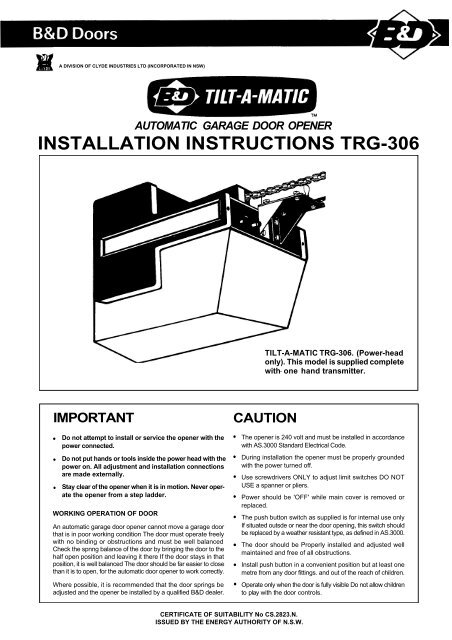
AUTOMATIC GARAGE DOOR OPENER<br />
<strong>INSTALLATION</strong> <strong>INSTRUCTIONS</strong> <strong>TRG</strong>-<strong>306</strong><br />
TILT-A-MATIC <strong>TRG</strong>-<strong>306</strong>. (Power-head<br />
only). This model is supplied complete<br />
with- one hand transmitter.<br />
IMPORTANT<br />
Do not attempt to install or service the opener with the<br />
power connected.<br />
Do not put hands or tools inside the power head with the<br />
power on. All adjustment and installation connections<br />
are made externally.<br />
Stay clear of the opener when it is in motion. Never operate<br />
the opener from a step ladder.<br />
WORKING OPERATION OF DOOR<br />
An automatic garage door opener cannot move a garage door<br />
that is in poor working condition The door must operate freely<br />
with no binding or obstructions and must be well balanced<br />
Check the spnng balance of the door by bringing the door to the<br />
half open position and leaving it there If the door stays in that<br />
position, it is well balanced The door should be far easier to close<br />
than it is to open, for the automatic door opener to work correctly.<br />
Where possible, it is recommended that the door springs be<br />
adjusted and the opener be installed by a qualified B&D dealer.<br />
CAUTION<br />
The opener is 240 volt and must be installed in accordance<br />
with AS.3000 Standard Electrical Code.<br />
During installation the opener must be properly grounded<br />
with the power turned off.<br />
Use screwdrivers ONLY to adjust limit switches DO NOT<br />
USE a spanner or pliers.<br />
Power should be 'OFF' while main cover is removed or<br />
replaced.<br />
The push button switch as supplied is for internal use only<br />
If situated outsde or near the door opening, this switch should<br />
be replaced by a weather resistant type, as defined in AS.3000.<br />
The door should be Properly installed and adjusted well<br />
maintained and free of all obstructions.<br />
Install push button in a convenient position but at least one<br />
metre from any door fittings. and out of the reach of children.<br />
Operate only when the door is fully visible Do not allow children<br />
to play with the door controls.<br />
CERTIFICATE OF SUITABILITY No CS.2823.N.<br />
ISSUED BY THE ENERGY AUTHORITY OF N.S.W.
<strong>INSTALLATION</strong> OF OPENER TO DOOR<br />
FIG. 1<br />
FIG. 1A<br />
<strong>INSTALLATION</strong> TO JAMB-TYPE FITTINGS<br />
<strong>INSTALLATION</strong> TO TRACK-TYPE FITTINGS<br />
FIG. 2<br />
STEP<br />
BEFORE STARTING <strong>INSTALLATION</strong>:<br />
Determine which type of garage door you have.<br />
EACH OF THE DIAGRAMS DESCRIBE AN IDEAL<br />
SITUATION, AND ARE DRAWN TO SCALE.<br />
It is suggested at all times, that installation be carried out<br />
by a qualified B&D dealer This is particularly important<br />
in situations of low or no headroom clearance.<br />
(Figs 1 ,1A,2)<br />
SPECIAL NOTE: Installation to Jamb-Type fittings:<br />
(i) Use straight connector arm. Do not use curved door<br />
arm (Also applicable for installation to track-type<br />
fittings.)<br />
(ii) Shorten drive tube to 1860mm. (Length of track from<br />
head of door to front of drive unit chassis will be<br />
1760mm.)<br />
(iii) Where headroom allows, maximum headroom adjustment<br />
(Refer Tilt-A-Dor 150J, 175J, 200J installation<br />
instruction sheet)<br />
IMPORTANT<br />
(iv) Locate the push button at least ONE METRE from the<br />
door fittings.<br />
<strong>INSTALLATION</strong> TO SECTIONAL OVERHEAD DOORS<br />
NOTE: Tilt-A-Dor and Panelift doors over 2200mm in<br />
height will require an extension kit and a longer tube
<strong>INSTALLATION</strong> OF CHAIN<br />
STEP 2<br />
Remove the sprocket cover (Fig.3) and position the trolley<br />
on the drive tube as illustrated (Fig.4).<br />
FIG. 3<br />
STEP 3<br />
NOTE: if the opener is to be applied to Jamb-Type<br />
Tilt-A-Dor fittings, refer instructions before proceeding.<br />
(Fig.1)<br />
Roll out the chain assembly carefully to prevent tangling.<br />
Connect the trolley release rod to the connecting link<br />
through the drive trolley, but do not tighten. (Fig.5)<br />
Wrap the chain around the idler and drive sprockets on<br />
the drive unit ensuring the chain engages the teeth on both<br />
sprockets.<br />
Extend the chain along the other side of the tube and<br />
around the return sprocket.<br />
Ensure the trolley has not moved from the point as<br />
indicated in the diagram. (Fig.4)<br />
Now install the connecting link to the trolley release rod<br />
as illustrated. (Fig.6)<br />
NOTE: During the assembly the trolley release rod is<br />
actually engaged in the trolley. It is shown here removed<br />
for the sake of clarity.<br />
FIG. 4<br />
CENTRE OF<br />
CHAIN<br />
FIG. 5<br />
6mm to 12mm<br />
CENTRE OF TUBE<br />
STEP 4<br />
Tension the chain by turning the adjusting nut. Hold the<br />
trolley release rod and the connecting link to prevent from<br />
turning. (Fig.6)<br />
The tension should be correct whan the chain has a sag<br />
of between 6mm and 12mm. (Fig.5)<br />
Tighten locknut against connecting link, to lock adjustment<br />
into place. (Fig.6)<br />
FIG. 6<br />
LLEY RELEASE<br />
NOTE: The chain and its supporting equipment may<br />
stretch after a period of time. The chain should be<br />
retightened after the first three months' use, and thereafter<br />
every two years.<br />
I<br />
ADJUSTING
MOUNTING WALL BRACKET AND DRIVE UNIT<br />
STEP 5<br />
NOTE: Most of the force applied by the opener while<br />
lifting and lowering the door is concentrated at the header<br />
bracket. It must be fixed to a beam or rigid support<br />
member<br />
Determine the centre of the door and mark this point on<br />
both the head of the opening and the top of the door.<br />
FIG. 7<br />
------<br />
HIGHEST POINT OF<br />
TRAVEL OF DOOR<br />
WALL BRACKET<br />
STEP 6<br />
NOTE: Refer to Step 1 to determine make and model of<br />
garage door.<br />
Lift the door and find the highest point of travel of the top<br />
of the door.<br />
Using a level, transfer this height to the head above the<br />
door. (Fig.7)<br />
STEP 7<br />
Place the bottom of the wall bracket at the height indicated<br />
in Step 6 and drill two 6mm pilot holes for the coach<br />
screws (Fig 8)<br />
The wall bracket may be mounted higher if required to<br />
avoid obstructions or overhead torsion springs.<br />
The powerhead will also have to be elevated in this cast?<br />
Attach return pulley assembly to wall bracket with 90mm<br />
clevis pin and clip.<br />
FIG. 8<br />
COACH SCREW<br />
STEP 8<br />
Raise the powerhead and support on a step ladder. Raise<br />
the door to the open position.<br />
Line the drive tube with the point market at the top of the<br />
door. Exact alignment is essential.<br />
To secure the opener. IT IS IMPERATIVE THAT THE<br />
POWERHEAD BE BRACED IN THE MANNER SHOWN<br />
AT RIGHT. (Fig.9)<br />
FIG. 9<br />
PERFORATED<br />
ANGLE
ADJUSTMENT LIMITS<br />
STEP 9<br />
NOTE: This step is to be completed before light<br />
diffuser installed.<br />
Adjust the door travel limits:<br />
Raise the door manually until the trolley passes over the<br />
trolley release rod and engages. Now plug the unit into<br />
a grounded three prong outlet.<br />
The limit screw adjusts where the door stops after<br />
travelling either up or down. The upper screw adjusts how<br />
far the door opens and the lowe screw adjusts the closed<br />
position. (Fig. 10)<br />
FIG. 10<br />
UP LIMIT<br />
, DOWN<br />
\ I<br />
STEP 10<br />
Operate the push button to send the unit to the upper limit.<br />
Adjust the upper knob to open the door properly. To raise<br />
the door, turn the upper screw to the left. One full turn<br />
of the screw is about eleven inches of travel at the door.<br />
Operate the push button to start the door in motion. The<br />
door will start travelling downward so push the button<br />
again to stop and once more to send the door up to the<br />
new limit setting. Readjust the limit and repeat the<br />
procedure as necessary.<br />
The down limit is adjusted the same way as the up limit.<br />
Turn the lower screw to the right to lower the closing<br />
position of the door. (Fig.11)<br />
FIG. 11<br />
UP LIMIT<br />
Turn clockwise<br />
for more travel<br />
DOWN LIMIT<br />
Turn counter-clockwise<br />
for more travel<br />
SAFETY SYSTEM<br />
STEP 11<br />
Safety system:<br />
The opener is equipped with an instant-reversing safety<br />
mechanism. Should the door contact an obstruction in its<br />
downward travel, it will automatically reverse directionand<br />
travel to the open position. The amount of force required<br />
to make the door reversein its down direction is adjustable<br />
by turning the screw on the front of the opener. (Fig.12)<br />
Check the safety system by manually holding the door<br />
back about midway in its downward travel. With only<br />
moderate pressure, the door should reverse. Turn the<br />
adjusting screw clockwise a turn a! a time to decreasethe<br />
force until the reversing action is correct. If the safety is<br />
set too sensitively, the door may not complete its downward<br />
travel. If the door starts down and reverses by itself,<br />
turn the adjustment screw counter clockwise to reduce<br />
sensitivity.<br />
FIG. 12<br />
To increase sensitivity<br />
of instant reversing safety<br />
mechanism turn clockwise<br />
\
PARTS LIST- DRIVE UNIT ASSEMBLY<br />
ITEM PART NO. DESCRIPTION<br />
NEUTRAL<br />
1 N1002 SCREW<br />
2 P2008 SPROCKET COVER<br />
3 TUBE DRIVE STD 2-755<br />
4 P2014 PULLEY WHEEL<br />
5 N7022 RIVET SEMI-TUBULAR<br />
6 S1014 TUBE BRACKET<br />
7 S1026 RETURN BRACKET<br />
8 N0047 CLEVIS PIN CLIP<br />
9 S1001 HEADER BRACKET<br />
10 N0046 CLEVIS PIN<br />
11 A4007 CHAIN449 LINK<br />
12 N0036 MACHINE SCREW<br />
13 N0043 WASHER<br />
14 N0041 SQUARE NUT<br />
15 N0039 HEX NUT<br />
16 P4015 TROLLEY ASSEMBLY<br />
17 N0045 CLEVIS PIN<br />
18 P0035 DISENGAGE PULL KNOB<br />
19 P2005 TROLLEYSTOP<br />
20 S 1003 DOORBRACKET<br />
21 S1008 L ARM<br />
22 S1007 DOOR ARM<br />
23 A0027 WELL NUT<br />
24 P3032 TROLLEY RELEASE ROD<br />
25 S3009 CHAIN CONNECTOR<br />
26 S1028 ROD CHAIN CONNECTOR<br />
16
PARTS LIST- POWERHEAD<br />
POWER CORD<br />
STRAIN RELIEF BUSHING<br />
WAVE SPRING WASHER<br />
TERMINAL BLOCK<br />
SPROCKET<br />
SIDE COVER LH<br />
COVER<br />
ADJUSTING SCREW<br />
SAFETY SPRING<br />
DOWN SAFETY<br />
MOUNT<br />
SAFETY WITCH<br />
WIRING HARNESS<br />
ONE PIECE BOARD<br />
ADJUSTING SCREW<br />
COVER FOR LIMIT SWITCH<br />
LIMIT SWITCH<br />
CAPACITOR<br />
CAPACITOR CLIP<br />
SNAP BUSHING<br />
LIGHT SOCKET<br />
MOTOR SHAFT BUSHING<br />
MOTOR SHAFT SPRING<br />
SPRING HOLDER<br />
THRUST BEARING<br />
T 8310 TAM TX 303 SINGLE CHANNEL<br />
T 8311 TAM TX 303 TWO CHANNEL<br />
DOWN SPRING HOLDER<br />
WASHER D 12 7MM<br />
WOODRUFF KEY<br />
COVER<br />
S SHAFT BUSHING
Motor hums. but does not start<br />
1 Defective capacitor (capacitor must be replaced)<br />
2 Check manual operation of door<br />
Relay clicks but motor does not start<br />
Motor has overheated, if the unit has been operated<br />
repeatedly its own thermal motor protector may shut<br />
it off Wait 15-20 minutes and try the push button or<br />
transmitter again<br />
Opener completely dead<br />
1 No line voltage to opener (check to see if there is<br />
power at the outlet)<br />
2 Defective board (Replace)<br />
3 Open circuit (Printed circuit)<br />
4 Defective capacitor (Replace)<br />
Light does not work<br />
1 Bulb burned out (Replace)<br />
2 Defective printed circuit board (Replace)<br />
Door reverses on down travel<br />
1 Safety set too light (Readjust)<br />
2 Garage door springs need adjustment<br />
3 Door is obstructed (Manually operate door to locate<br />
obstructions)<br />
4 Door closes too hard against door opening or jambs<br />
(Adjust down limit)<br />
Door stops on way up<br />
1 Garage door springs need adjustment (Door may be<br />
too heavy)<br />
2 Door binding in track (Manually operate door to locate<br />
binding)<br />
Opener responds to push button but not<br />
hand transmitter<br />
1 Check for defective hand transmitter battery (Check<br />
light on transmitter)<br />
2 Relocate hand transmitter in car<br />
3 Press hand transmitter within 3 metres of door If this<br />
works check the antenna<br />
4 The range of the signal can be adjusted with the<br />
screw located at the back of the nand transmitter<br />
casing Care must be taken as the tuning is very sensitive<br />
T h escrewdriver must be removed from the slot<br />
while checking the range<br />
Opener responds to hand transmitter but not<br />
push button<br />
1 Check push button wire for break or open circuit<br />
STANDARD ACCESSORIES<br />
FAILSAFE CIRCUIT<br />
As an additional safety precaution a FAILSAFE CIRCUIT has been incorporated into the main circuit if for any<br />
reason the safety reverse system fails the FAILSAFE CIRCUIT will assume control and within 30 seconds automatically<br />
reverse the door<br />
C OURTESY LIGHTS<br />
Courtesy lights will be activated whenever the door is operated, and will remain alight for approximately 4½ minutes<br />
before automatically switching off<br />
OPTIONAL ACCESSORIES<br />
Domino lock, Key switch, Two position hand transmitter, Emergency key release.<br />
Drive Tube Extension kit comprise's 305mm-380mmtube, 610mm-760mm chain and master link (Lifts door height<br />
up to 2500mm when applied)<br />
IMPORTANT<br />
Always locate the push button at least ONE METRE from the door fittings.<br />
NEW SOUTH WALES<br />
B &DDoors<br />
34-36 Marigold Street.<br />
Revesby 2212<br />
Phone (02) 771 5566<br />
VICTORIA QUEENSLAND SOUTH AUSTRALIA<br />
B & D Doors<br />
B & D Doors<br />
B & D Doors<br />
Canlerbury Road 37 47 Cobalt Street 5 Peekarra Street<br />
Kilsyth 3137 Carole Park 4300 Regency Park 5010<br />
Phone (03) 728 1566 Phone (07)27' 2500 Phone (08) 340 341 1<br />
WESTERN AUSTRALIA WESTERN AUSTRALIA TASMANIA<br />
Osborne Metal industries P/L G.K. Cameron & Co P/L Tom Moore & Son<br />
225 Balcatta Road 246 Churchill Avenue 86 Bass Highway<br />
Balcatta 6021 Subiaco 6008 Cooee 7320<br />
Phone 1091 344 3333 Phone (09) 381 3800 Phone (004) 31 4388<br />
(For Controll-A-Door) (For Tilt-A-Matic) (For Controll-A-Door)<br />
TASMANIA<br />
Tasman Door Centre<br />
209 Invermay Road<br />
Launceston7250<br />
Phone (003) 26 1301<br />
(For