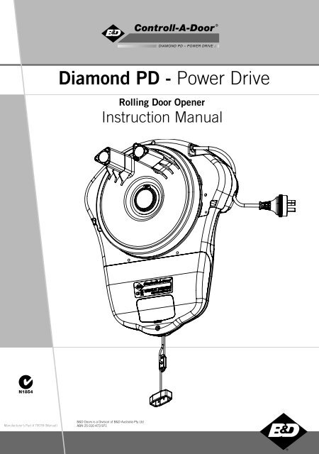
Diamond PD - Power Drive
RDO-1v2 (CAD Diamond PD) Manual.indd - Capital Doorworks
RDO-1v2 (CAD Diamond PD) Manual.indd - Capital Doorworks
- No tags were found...

You also want an ePaper? Increase the reach of your titles
YUMPU automatically turns print PDFs into web optimized ePapers that Google loves.
<strong>Diamond</strong> <strong>PD</strong> - <strong>Power</strong> <strong>Drive</strong><br />
Rolling Door Opener<br />
Instruction Manual<br />
N1854<br />
Manufacturer’s Part # 79078 (Manual)<br />
B&D Doors is a Division of B&D Australia Pty Ltd<br />
ABN 25 010 473 971<br />
www.bnd.com.au
2<br />
Controll-A-Door ® <strong>Diamond</strong> <strong>PD</strong> - <strong>Power</strong> <strong>Drive</strong> Instruction Manual<br />
<strong>Diamond</strong> <strong>PD</strong> - <strong>Power</strong> <strong>Drive</strong><br />
Rolling Door Opener<br />
Safety Rules 03<br />
System Specification 04<br />
About Your B&D Opener 05<br />
Operating Controls 06<br />
Kit Contents 07<br />
Installation & Setup 08<br />
Pre-Installation Requirements 08<br />
Installation 09<br />
Setting Travel Limits 12<br />
Resetting Travel Limits 12<br />
Coding Transmitters 13<br />
Safety Test 15<br />
Accessories 16<br />
Safety Infra-red Beam 16<br />
Electric Key Witch 16<br />
Remote Aerial 17<br />
Terminal Black 17<br />
How To Use Your Opener 18<br />
Remote Control Transmitter 18<br />
Inbuilt Locking Facility 19<br />
Manual Door Operation 19<br />
<strong>Power</strong> Failure 19<br />
Safety Infra-red Beam 20<br />
Auto-Close 20<br />
Courtesy Light 20<br />
Auxiliary Output 20<br />
Vacation Mode 20<br />
Pet Mode 20<br />
Door Status Indicator 20<br />
Optional Accessories 21<br />
Maintenance 22<br />
Troubleshooting Guide 23<br />
Spare Parts 24<br />
Warranty 26
Controll-A-Door ® <strong>Diamond</strong> <strong>PD</strong> - <strong>Power</strong> <strong>Drive</strong> Instruction Manual<br />
3<br />
Safety Rules<br />
Please read these important safety rules<br />
These safety alert symbols indicate a personal safety or property damage<br />
instruction exists. READ THESE INSTRUCTIONS CAREFULLY.<br />
This automatic garage door opener is designed and tested to offer safe<br />
service provided it is installed and operated in strict accordance with the<br />
following safety rules. Failure to comply with the following instructions may<br />
result in death, serious personal injury or property damage.<br />
CAUTION: If your garage has no pedestrian entrance<br />
door, an emergency access device should be installed<br />
to allow manual garage door operation from outside in the<br />
case of power failure.<br />
Position the Garage Door Opener so that the power<br />
plug is accessible when inserted into the power<br />
outlet (EN 60335-1).<br />
This opener should be installed in accordance with<br />
relevant Australian Standards.<br />
Do not allow children to play with door controls .<br />
Keep remote controls away from children .<br />
Watch the moving door and keep people away until<br />
the door is completely opened or closed .<br />
Activate the opener only when the garage door is in<br />
full view, free of obstructions and with the opener<br />
properly adjusted.<br />
Keep garage door balanced. Sticking or binding doors<br />
must be repaired. Garage doors, door springs,<br />
brackets and their hardware are under extreme tension<br />
and can cause serious personal injury. Do not attempt any<br />
garage door adjustment. Do not use if repair or adjustment is<br />
needed. Call for professional garage door service.<br />
Install optional door control button in a location where<br />
the garage door is visible, but out of the reach of<br />
children at a height of at least 1.5m .<br />
Do not wear rings, watches or loose clothing while<br />
installing or servicing a garage door opener.<br />
This opener is not suitable for commercial,<br />
industrial or common entry applications.<br />
To avoid serious personal injury from entanglement,<br />
remove all unnecessary ropes or chains and<br />
disable any equipment such as locks which are not<br />
needed for powered operation .<br />
Installation and wiring must be in compliance<br />
with your local building and electrical codes.<br />
Connect the power cord only to properly earthed<br />
mains. If an extension lead is used, make sure it is a 3<br />
core lead and approved to 7 amp capacity.<br />
If the supply cord is damaged, it must be replaced<br />
by the manufacturer or its service agent or a<br />
similarly qualified person in order to avoid a hazard.<br />
When using optional auto close mode, a safety<br />
Infra-Red beam (Part No 062153) must be fitted<br />
correctly and tested for operation at regular intervals.<br />
Extreme caution is recommended when using auto<br />
close mode. All safety rules must be followed.<br />
This opener is a plug in domestic appliance and is<br />
designed for indoor use only. It must be installed<br />
in a dry position that is protected from the weather.<br />
The opener is not intended for use by young<br />
children or infi rm persons without supervision.<br />
Disconnect electric power to the garage door opener<br />
when cleaning or carrying out other maintenance.<br />
Garage doors needing over 400N of force to move<br />
must have Safety Infra-red Beams installed<br />
WARNING! It is vital for the safety of<br />
persons to follow all instructions. Save<br />
these instructions.<br />
B&D Doors to the extent that such may be lawfully excluded hereby expressly disclaims all conditions or warranties, statutory or otherwise which may be implied by laws<br />
as conditions or warranties of purchase of a B&D Doors Garage Door Opener. B&D Doors hereby further expressly excludes all or any liability for any injury, damage, cost,<br />
expense or claim whatsoever suffered by any person as a result whether directly or indirectly from failure to install the B&D Doors Garage Door Opener in accordance<br />
with these installation instructions.<br />
© Copyright January 2008 B&D Doors<br />
<strong>Diamond</strong> <strong>PD</strong> <strong>Power</strong> <strong>Drive</strong> : Instruction Manual
4<br />
Controll-A-Door ® <strong>Diamond</strong> <strong>PD</strong> - <strong>Power</strong> <strong>Drive</strong> Instruction Manual<br />
System Specifications<br />
Maximum Door Size<br />
Door Load<br />
Supply Voltage<br />
Current<br />
Lamp<br />
Limit Adjustment<br />
Force Control<br />
Transmitter Frequency<br />
<strong>Power</strong>head Weight<br />
Door Drum Rotation<br />
Auxiliary <strong>Power</strong> Supply<br />
Rated Load<br />
Door Closed Status<br />
Output<br />
Auxiliary Output Supply<br />
External Aerial Connection<br />
3000mm high 5500mm wide (16.5m 2 ) residential rolling garage door, or 2400mm<br />
high wind lock residential rolling garage door<br />
Rated Load: 550N<br />
Recommended Load: 200N (20kgs).<br />
Ideal Load: 70N (7kgs)<br />
230 - 240 V AC 50Hz<br />
Max. 1A<br />
LED (Light Emitting Diode) lighting; 2 X LED modules. Light comes on when door<br />
starts, off approx. 4½ minutes later, or can be programmed to operate from a remote<br />
control transmitter<br />
Electronic<br />
Electronic - fully automatic. Can be adjusted for environmental reasons<br />
433.92MHz<br />
7.6kg Max.<br />
3 Turns<br />
24-35VDC at 100mA<br />
550N<br />
Opto-isolated transistor output 35V 100mA. Connected to GND when door closed<br />
Note: Output will not be activated after power failure until a closed drive cycle has<br />
been completed - even if the door is closed<br />
Opto-isolated transistor output 35V 100mA. Connected to GND when activated<br />
2-Pin Screw Connector
Controll-A-Door ® <strong>Diamond</strong> <strong>PD</strong> - <strong>Power</strong> <strong>Drive</strong> Instruction Manual<br />
5<br />
About Your B&D Opener<br />
Thank you for choosing a B&D automatic garage door<br />
opener. This automatic garage door opener has been<br />
designed and developed in Australia by B&D Doors.<br />
The technically advanced construction of this B&D opener<br />
ensures you enjoy the following benefi ts:<br />
Warranty<br />
Five (5) year/10,000 cycles full parts and labour warranty<br />
on motor, electronics and mechanical components of<br />
the opener when installed by an authorized B&D Dealer<br />
(conditions such as having the garage door serviced<br />
annually also apply).<br />
Tri-Tran Frequency Hopping Technology<br />
Every time a transmitter is used, it simultaneously sends a<br />
signal over three different frequencies, reducing the chance<br />
of interference from other radio frequency sources.<br />
Code Hopping Technology<br />
Every time a transmitter is used a new security code is<br />
generated from over 4.29 billion possible combinations.<br />
Multi-Channel Transmitter<br />
Multi-channel transmitters allow you to operate other<br />
devices such as an adjoining garage door or automated<br />
gate from the same handy unit.<br />
Soft Start/Soft Stop<br />
The opener eases into and out of each cycle for smooth<br />
and quiet operation, and also to reduce wear on the door<br />
and opener.<br />
Warranty Expired Indicator<br />
When the opener reaches the number of cycles covered<br />
by warranty, the courtesy light will flash 10 times after<br />
each cycle, for the next 20 cycles, to indicate this. This<br />
can be reset by pressing the LIMIT SET button while<br />
the courtesy light is fl ashing.<br />
Safety Reversing System<br />
Automatic safety reverse ensures personal protection from<br />
death or serious injury if trapped under a door while closing.<br />
Safety reverse force can be adjusted for environmental<br />
conditions, for example windy areas, etc.<br />
LED Courtesy Light<br />
Taking advantage of the latest advances in Light Emitting<br />
Diode (LED) technology, the opener features two light<br />
modules consisting of ten LEDs each, which produces a<br />
brilliant white light to illuminate the garage.<br />
The LED courtesy light automatically switches on for<br />
approximately 4 1⁄2 minutes (time programmable) when<br />
operating the door. This can also be programmed to turn<br />
on and off from a remote control transmitter.<br />
Manual Release<br />
Emergency manual release handle for manual<br />
operation of the door in the event of a power failure.<br />
Memory Retention<br />
In case of a power failure the opener does not lose the<br />
transmitter codes or limits settings.<br />
Self Locking<br />
No need to manually lock your garage door, as the<br />
opener ‘positively’ locks the door when closed.<br />
Periodic Maintenance Indicator<br />
The service LED will illuminate to indicate that periodic<br />
maintenance is required. Contact your dealer/installer<br />
for service.<br />
Service Fault Indicator<br />
Flashing LED’s on the control panel easily identify<br />
operational problems or service requirements.<br />
Dynamic Door Profiling<br />
Automatically compensates for changes in door<br />
operating characteristics.<br />
Auto-Close<br />
Auto closing option can be programmed to close<br />
the door approximately 30 seconds after the door<br />
has opened. N.B. Safety Infra-Red Beams must be<br />
installed for this option to function.<br />
External Antenna<br />
An external antenna can be connected - for sites<br />
where radio reception is a problem.<br />
Vacation Mode<br />
A transmitter can be programmer to disable the garage<br />
door opener radio receiver. This is ideal if the door is to<br />
be left idle for prolonged periods.<br />
Pet Mode<br />
A transmitter can be programmed to open the door<br />
partially to allow pets access to the garage. The door<br />
opening height is adjustable via a handheld programmer.<br />
Door Status<br />
(CLS Out) Door Closed Output indicates when the door<br />
is in the closed position.<br />
Auxiliary Output<br />
You can program a spare button of you remote control<br />
transmitter to operate this output to control items that<br />
can be switched using a momentary close.<br />
Battery Back Up<br />
Optional battery back up or solar power is available.<br />
© Copyright January 2008 B&D Doors<br />
<strong>Diamond</strong> <strong>PD</strong> <strong>Power</strong> <strong>Drive</strong> : Instruction Manual
6<br />
Controll-A-Door ® <strong>Diamond</strong> <strong>PD</strong> - <strong>Power</strong> <strong>Drive</strong> Instruction Manual<br />
Operating Controls<br />
01<br />
02<br />
15<br />
14<br />
10<br />
03<br />
04<br />
05<br />
13<br />
12<br />
11<br />
06<br />
09<br />
07 08<br />
01. Fuse<br />
02. Terminal block:<br />
GND<br />
IR Beam<br />
30v PWR<br />
OPERATE<br />
CLS OUT<br />
AUX OUT<br />
03. LED light array<br />
04. Antenna terminal<br />
05. SERVICE LED indicator (yellow)<br />
06. OPERATE button (blue)<br />
07. LIMIT SET button (black)<br />
08. CODE SET LED indicator (red)<br />
09. MINUS (-) and code set button (red)<br />
10. PLUS (+) button (green)<br />
11. CLOSE LIMIT LED indicator (red)<br />
12. OPEN LIMIT LED indicator (green)<br />
13. Jumpers:<br />
OPT 1<br />
OPT 2<br />
AUTO-CLS<br />
14. Universal programmer connector<br />
15. Battery back up connector<br />
16. Manual release handle
N1854<br />
<br />
<br />
<br />
<br />
Controll-A-Door ® <strong>Diamond</strong> <strong>PD</strong> - <strong>Power</strong> <strong>Drive</strong> Instruction Manual<br />
7<br />
Kit Contents<br />
<br />
<br />
1. 2. 3. 4.<br />
1. <strong>Power</strong>head<br />
2. Weight Bar<br />
3. Instruction manual and warning labels<br />
4. Installation and Operating Items, including:<br />
a.<br />
b.<br />
c.<br />
d.<br />
e.<br />
f.<br />
g.<br />
h.<br />
i.<br />
j.<br />
k.<br />
l.<br />
m.<br />
n.<br />
o.<br />
Qty 2 Keyring remote control transmitters<br />
Qty 2 Screw M4 x 50<br />
Qty 2 3/16x1/2 fl at washers<br />
Qty 2 5/32 shakeproof washer<br />
Qty 2 Nut M4 hex<br />
Qty 2 Hex serration head screw M6x45<br />
Qty 2 Flat washer 107D 6.4x20.5x1.6<br />
Qty 2 Extension fork 58L<br />
Qty 2 Screw 10x32 self tapping<br />
Qty 2 Washer 6.4x20.6x1.2 to pin the door<br />
curtain<br />
Qty 2 Cover with D/S tape<br />
Qty 1 Collar kit<br />
Qty 1 Transmitter wall bracket<br />
Qty 2 Wall bracket screw<br />
Qty 2 Wall plug<br />
© Copyright January 2008 B&D Doors<br />
<strong>Diamond</strong> <strong>PD</strong> <strong>Power</strong> <strong>Drive</strong> : Instruction Manual
8<br />
Controll-A-Door ® <strong>Diamond</strong> <strong>PD</strong> - <strong>Power</strong> <strong>Drive</strong> Instruction Manual<br />
Pre-Installation Requirements<br />
WARNING! Incorrect installation can<br />
lead to severe injury - FOLLOW ALL<br />
INSTALLATION INSTRUCTIONS.<br />
Fig.01<br />
Door Operation<br />
The door must be in good operating condition. The<br />
maximum effort to move the door up or down, from<br />
stationary, should not exceed 200 Newtons (20kg force) at<br />
the bottom rail. The recommended force is 70N (7kg) for<br />
manual operation.<br />
Lift the door to about halfway. When released, the door should<br />
stay in place supported entirely by its springs. Also raise and<br />
lower the door to check for any binding or sticking.<br />
The door may need to be serviced to meet these<br />
requirements – refer to the door manufacturer’s servicing<br />
instructions or contact an authorised dealer.<br />
Unsuitable Door Types<br />
The fi tting of an opener to doors with removable mullions is<br />
not recommended.<br />
IMPORTANT NOTE - The opener should<br />
not be installed on any door incorporating a<br />
wicket door.<br />
Fig.02<br />
Position<br />
The opener can be installed on either the right hand or left<br />
hand side of the door (when viewed from inside the garage).<br />
The opener is factory set for right hand side installation.<br />
This opener must be installed in a dry position that is<br />
protected from the weather. Moisture or corrosion damage<br />
is not covered by the Warranty.<br />
<strong>Power</strong> Supply<br />
A properly earthed 3 pin single-phase power supply is<br />
required.<br />
WARNING! A portable power generator is<br />
not recommended. The opener may appear<br />
to malfunction due to spikes, surges and<br />
fluctuations in the generated voltage.<br />
Side room<br />
The minimum side room required from the edge of the<br />
door curtain is 41mm to the inside of the door bracket, and<br />
85mm to the wall (Fig. 01).<br />
The recommended side room from the edge of the door<br />
curtain is 95mm to the inside of the door bracket, and<br />
135mm to the wall (Fig. 02).<br />
NOTE: Door Axle Diameter must not exceed 35mm.
Controll-A-Door ® <strong>Diamond</strong> <strong>PD</strong> - <strong>Power</strong> <strong>Drive</strong> Instruction Manual<br />
9<br />
Installation<br />
Step 1 - Preparation<br />
a. Check the door’s operation:<br />
i.<br />
b.<br />
ii.<br />
iii.<br />
iv.<br />
The door must travel smoothly and be easy<br />
to operate by hand.<br />
Operating force on the bottom rail should be<br />
approximately 70N (7kgs) force.<br />
Adjust any tight or twisted guides/tracks<br />
Clean the guides if there is any oil or wax<br />
present using a suitable white spirit. The only<br />
lubricant suitable for use on door guides is<br />
silicon spray. DO NOT use WD-40, RP-7,<br />
petroleum grease, or similar.<br />
Install the locking bar covers if there are locking bar<br />
holes in the guides. (Fig.03)<br />
IMPORTANT NOTE - Do not lock your door<br />
with the locking bars after installing the<br />
opener. Remove or disable the lock using wire<br />
or cable ties. Security is not affected as the<br />
opener has an inbuilt locking facility.<br />
Fig.03<br />
Fig.04<br />
c.<br />
d.<br />
Affi x the warning labels supplied with this opener in a<br />
prominent place where they are clearly visible.<br />
Choose the side where the opener will be installed<br />
ensuring there is suffi cient sideroom.<br />
Step 2 - Fit the Weight Bar<br />
The weight bar must be fitted to the bottom-centre for<br />
proper operation of the opener.<br />
If the door has a handle:<br />
a. Remove the door handle<br />
b. Fit the weight bar and refi t the handle using the new<br />
fasteners provided (Fig.04).<br />
If the door does not have a handle:<br />
a. Locate the centre of the door at the bottom rail<br />
(Fig.05).<br />
b. Place the weight bar at this point (there is a centreline<br />
marked on the weight bar) and mark the two positions<br />
where the fasteners will go<br />
c. Drill the two 4.5mm holes in the door and fit the weight<br />
bar using the new fasteners provided. (Fig.06).<br />
Fig.05<br />
Check that the door is still balanced and smooth to operate.<br />
If it is not then the door may require servicing (refer to door<br />
manufacturer’s instructions).<br />
WARNING! The door and its springs are under<br />
significant tension. Adjustments should only<br />
be carried out by experienced persons, as this<br />
function can be dangerous if not performed<br />
under strict safety procedures.<br />
Fig.06<br />
© Copyright January 2008 B&D Doors<br />
<strong>Diamond</strong> <strong>PD</strong> <strong>Power</strong> <strong>Drive</strong> : Instruction Manual
10<br />
Controll-A-Door ® <strong>Diamond</strong> <strong>PD</strong> - <strong>Power</strong> <strong>Drive</strong> Instruction Manual<br />
Installation<br />
Door drum<br />
Step 3 - Pin the Door Curtain<br />
Pinning the door curtain to the door drum maintains security<br />
when the opener closes and locks.<br />
Fig.07<br />
Pin Points<br />
a.<br />
b.<br />
c.<br />
d.<br />
Fully close the door.<br />
Mark drill holes at both ends of the drum (Fig. 07).<br />
Drill holes using 3.2mm (1/8”) drill bit. Open the door<br />
slightly for easier access, if necessary.<br />
Fit a 10 x 32mm screw and washer to each end. This<br />
screw should be positioned as low as possible, but<br />
make sure that it does not alter the curtain’s normal<br />
approach to the guide (lead-in angle).<br />
Fig.08<br />
U-bolt<br />
Bracket<br />
NOTE: Make sure that the screws do not project into the<br />
area where the internal gear will fi t.<br />
Step 4 - Fitting the opener<br />
a. At the end opposite to where the opener will be fitted,<br />
check that the U-bolt is tightened securely. Fit the<br />
anti-coning collar (supplied) to the axle flush with the<br />
door drum.<br />
b. Open the door completely and tie safety ropes around<br />
the door roll approximately 300mm from each end.<br />
Do not tie the ropes too tight as damage to the curtain<br />
may ensue.<br />
c. At the end where the opener is to be fitted, support<br />
the door with a ladder or suitable prop:<br />
WARNING! Make sure the support is snug<br />
under the door, are stable and will not move.<br />
d.<br />
e.<br />
f.<br />
At the end where the opener will be fitted use masking<br />
tape or pen to mark the position of the U-bolt in the<br />
door bracket and the position of the door bracket on<br />
the wall to assist to assist in reassembling.<br />
Remove the U-bolt (or bolts) and saddle from the door<br />
bracket.<br />
Remove the door bracket allowing the door to rest on<br />
the support (Fig. 08).<br />
NOTE - For minimum sideroom installations<br />
the door may have to be taken down.<br />
WARNING! The opener must not be used with<br />
a door incorporating a wicket door.
Controll-A-Door ® <strong>Diamond</strong> <strong>PD</strong> - <strong>Power</strong> <strong>Drive</strong> Instruction Manual<br />
11<br />
Installation<br />
WARNING! The opener should not be installed<br />
where the door opens over a public footpath<br />
or roadway.<br />
M6 x 45 Hex Screw<br />
Washer 6.4 x 20 x 1.6<br />
Step 5 - Assemble the Internal Gear<br />
a. Insert the two forks into the ring gear (Fig. 09).<br />
b. Secure with M6x45 hex serration head screw and<br />
washer.<br />
Extension Fork<br />
Fig.09<br />
Step 6 - Mounting the Opener<br />
a. If the internal gear does not rotate freely switch the<br />
opener to manual by pulling the disengagement<br />
handle down (there will be a click), so that the ring<br />
gear can be rotated by hand.<br />
b. Slide the opener over the door axle and into the drum<br />
of the door (Fig. 10).<br />
c. Ensure the internal gear is pushed in as far as possible<br />
(without interfering with the door curtain) and that<br />
one of the door drum’s wheel spokes is completely<br />
between the opener’s drive forks.<br />
d. Re-attach the door bracket using your reference<br />
marks as a guide and tighten the bolts. Ensure that<br />
the slots in the mounting bracket of the opener align<br />
with the slots in the door bracket, otherwise the door<br />
bracket may have to be relocated (Fig. 11).<br />
» If the bracket cannot be relocated, the opener<br />
may be fi tted onto the axle using the opener’s<br />
saddle and U-bolt as follows:<br />
i. Using your reference marks as a guide, sit<br />
the opener on the door mounting bracket<br />
and secure with the opener’s U-bolt and<br />
saddle and tighten fi rmly.<br />
ii. Adjust the door position (if necessary)<br />
on the brackets so that the door feeds<br />
smoothly into the guides. Make sure that<br />
the centre of the door doesn’t hit the lintel<br />
and that the curtain is not pushed forward<br />
hard into the guide.<br />
e. Remove the support and safety ropes (Fig. 11).<br />
IMPORTANT NOTE - If the manual release<br />
handle is more than 1.8 metres from floor level<br />
when the opener is installed, extend the handle<br />
to a height less than 1.8 metres.<br />
Untie rope<br />
Remove prop<br />
Pull manual release<br />
handle if gear does<br />
not rotate freely<br />
Re-fit bracket<br />
Fig.10<br />
Fig.11<br />
f.<br />
g.<br />
Connect the power cord to a suitable power point, but<br />
DO NOT SWITCH ON. Secure the power cord away<br />
from any moving object (e.g. the door) with the cable<br />
clip supplied.<br />
With the opener still disengaged, pull the door up and<br />
down to make sure it runs freely<br />
Tighten U-bolt<br />
© Copyright January 2008 B&D Doors<br />
<strong>Diamond</strong> <strong>PD</strong> <strong>Power</strong> <strong>Drive</strong> : Instruction Manual
12<br />
Controll-A-Door ® <strong>Diamond</strong> <strong>PD</strong> - <strong>Power</strong> <strong>Drive</strong> Instruction Manual<br />
Setting Travel Limits<br />
Step 7.1 - Setting Travel Limits<br />
Fig.12<br />
NOTE: If Infra-red Safety Beams are to be used they must be<br />
installed before setting the travel limits.<br />
WARNING! Use caution when operating the<br />
manual release with the door open since it<br />
may fall rapidly due to weak or broken springs,<br />
or an improperly balanced door.<br />
CAUTION! Do not disengage the opener to<br />
manual operation with children, persons or<br />
any objects including motor vehicles within<br />
the doorway.<br />
a.<br />
b.<br />
c.<br />
d.<br />
e.<br />
f.<br />
g.<br />
h.<br />
Move the door to half way open. If necessary, disengage<br />
the opener by pulling the red handle down.<br />
Re-engage the opener by pulling the red handle down.<br />
Turn on the power to the opener. The CLOSE LIMIT<br />
LED will be flashing.<br />
Press and hold the MINUS (-) button - the door should<br />
starting closing (Fig. 12).<br />
» If the door opens, release the MINUS (-) button<br />
and press the OPERATE button once to change<br />
the motor’s direction. Press the MINUS (-) button<br />
again to close the door.<br />
Release the MINUS (-) button when the door is near the<br />
desired closed position. Single presses of the MINUS<br />
(-) button will “inch” the door closed.<br />
» If the door overshoots press the PLUS (+) button to<br />
move the door in the open direction.<br />
When the door is at the desired close position, press<br />
the LIMIT SET button to record the Close limit position.<br />
The OPEN LIMIT LED will now flash.<br />
Press and hold the PLUS (+) button to open the door<br />
Release the PLUS (+) button when the door is near the<br />
desired open position. Single presses of the PLUS (+)<br />
button will “inch” the door open.<br />
» If the door overshoots press the MINUS (-) button<br />
to move the door in the open direction.<br />
WARNING! Once the next step is performed,<br />
the door will automatically close and open.<br />
Keep persons and objects clear of the door<br />
until it stops and the opener sounds a beep.<br />
i.<br />
Press the LIMIT SET button to store the open limit.<br />
Please read the above warning.<br />
Step 7.2 - Resetting Travel Limits<br />
To reset the limits press and hold the LIMIT SET button for 6<br />
seconds until the Close Limit LED flashes quickly. If no action<br />
is taken within 30 seconds, the opener will return to normal<br />
operating mode and restore the original limit settings
Controll-A-Door ® <strong>Diamond</strong> <strong>PD</strong> - <strong>Power</strong> <strong>Drive</strong> Instruction Manual<br />
13<br />
Coding Transmitters<br />
Step 8.1 - Storing the Transmitter Code<br />
The opener can only operated from remote control<br />
transmitters that have been programmed into its memory.<br />
Up to fourteen (14) codes can be stored in the memory.<br />
a.<br />
b.<br />
c.<br />
d.<br />
e.<br />
Ensure that the battery is inserted in the transmitter.<br />
Press the CODE SET button and release. The CODE<br />
SET LED will illuminate to indicate the opener is in<br />
Code Learn mode. If a valid code is not stored within<br />
15 seconds the opener will exit Code Learn (Fig. 13).<br />
Press the transmitter button (one of four) that you want<br />
to control the door. The CODE SET LED will flash.<br />
Press the same transmitter button again. The CODE<br />
SET LED will illuminate for one second then go out.<br />
The transmitter button is now coded - press to test.<br />
Press CODE SET<br />
button once<br />
Select one of the<br />
four buttons (not<br />
programmed yet ) you<br />
wish to use to control<br />
the door<br />
Fig.13<br />
Step 8.2 - Setting the Transmitter to Operate the<br />
Courtesy Light Independently of the Door<br />
Although the courtesy light comes on with each operation of<br />
the opener, it may also be controlled by a transmitter without<br />
operating the door.<br />
a.<br />
b.<br />
c.<br />
d.<br />
Press the CODE SET button twice - The CODE SET LED<br />
and courtesy light will both illuminate (Fig. 14).<br />
Press a transmitter button not already coded into the<br />
receiver - the CODE SET LED will begin to flash.<br />
Press the same transmitter button again. The CODE<br />
SET LED will illuminate for one second then go out.<br />
The transmitter button is now coded - press to test.<br />
Press CODE SET<br />
button twice<br />
Select one of the<br />
four buttons (not<br />
programmed yet ) you<br />
wish to use to control<br />
the courtesy light<br />
Fig.14<br />
Step 8.3 - Setting the Transmitter to Operate<br />
Vacation Mode<br />
The opener can be programmed into a “Vacation Mode”<br />
where the opener will not respond to any transmitter except<br />
one preprogrammed unit.<br />
a.<br />
b.<br />
c.<br />
d.<br />
e.<br />
Press CODE SET button three times. The CODE SET<br />
LED will illuminate and the courtesy light will flash<br />
slowly (Fig. 15).<br />
Press a transmitter button not already coded into the<br />
receiver - the CODE SET LED will begin to flash.<br />
Press the same transmitter button again. The CODE<br />
SET LED will illuminate for one second and then go out,<br />
and the courtesy light will also switch off. This indicates<br />
the code has been stored.<br />
To activate Vacation Mode, close the garage door and<br />
press the coded button for 5 seconds. The CODE SET<br />
LED will illuminate and stay on.<br />
To exit Vacation Mode press the transmitter button<br />
momentarily until the CODE SET LED turns off.<br />
Press CODE SET<br />
button three times<br />
Select one of the<br />
four buttons (not<br />
programmed yet ) you<br />
wish to use to control<br />
the Vacation Mode<br />
Fig.15<br />
© Copyright January 2008 B&D Doors<br />
<strong>Diamond</strong> <strong>PD</strong> <strong>Power</strong> <strong>Drive</strong> : Instruction Manual
14<br />
Controll-A-Door ® <strong>Diamond</strong> <strong>PD</strong> - <strong>Power</strong> <strong>Drive</strong> Instruction Manual<br />
Coding Transmitters<br />
Step 8.4 - Setting the Transmitter to Operate the<br />
Auxiliary Output<br />
It is possible to operate other devices (e.g. alarm systems)<br />
using one of the spare buttons of a multi-channel transmitter<br />
coded into the Auxiliary Output feature.<br />
Fig.16<br />
Press CODE SET<br />
button four times<br />
Select one of the<br />
four buttons (not<br />
programmed yet ) you<br />
wish to use to control<br />
the auxiliary output<br />
a.<br />
b.<br />
c.<br />
Press CODE SET button four times. The CODE SET LED<br />
will illuminate and the courtesy light will flash quickly<br />
(Fig. 16).<br />
Press a transmitter button not already coded into the<br />
receiver - the CODE SET LED will begin to flash.<br />
Press the same transmitter button again. The CODE<br />
SET LED will illuminate for one second and then go out.<br />
Step 8.1 - Storing the Transmitter Code<br />
Step 8.5 - Setting the Transmitter to Operate Pet<br />
(Pedestrian) Mode<br />
The opener can be programmed into a “Pet Mode” where the<br />
door opens partially to allow pets to enter/exit the garage:<br />
Fig.17<br />
Press CODE SET<br />
button five times<br />
Select one of the<br />
four buttons (not<br />
programmed yet ) you<br />
wish to use to control<br />
pet mode<br />
a.<br />
b.<br />
c.<br />
Press the CODE SET button five times, the CODE SET<br />
LED will illuminate and the courtesy light will flash<br />
quickly (twice per second) to indicate learning mode for<br />
Pet Mode is active (Fig. 17).<br />
Choose a transmitter button not already coded into the<br />
receiver. Press this button and the CODE SET LED will<br />
begin to flash.<br />
Press the same transmitter button again. The CODE<br />
SET LED will illuminate for one second and then go out,<br />
and the courtesy light will also switch off. This indicates<br />
the code has been stored. This indicates the code has<br />
been stored (Fig. 34).<br />
Fig.18<br />
Step 8.6 - To Erase Programmed Codes<br />
If the CODE SET button is pressed and held for 6 seconds the<br />
CODE SET LED will blink rapidly for one second to indicate<br />
that all programmed codes have been erased. (Fig. 18)<br />
Fig.19<br />
Step 8.7 - Installation of the optional Wall Mounted<br />
Transmitter<br />
a. Mount the transmitter in a convenient location, yet out<br />
of reach of children and at least 1.5m off the ground<br />
(Fig. 19).<br />
b. Make sure the door is visible from this location.<br />
c. To set the transmitter codes refer to Step 8.1.
Controll-A-Door ® <strong>Diamond</strong> <strong>PD</strong> - <strong>Power</strong> <strong>Drive</strong> Instruction Manual<br />
15<br />
Safety Test<br />
Step 9.1 - Door Closing Test<br />
a. Ensure that the door is open.<br />
b. Place a 40mm obstacle flat on the fl oor under the<br />
middle of the garage door (Fig. 20).<br />
c. Operate the door in the close direction; the door must<br />
reverse on hitting the obstruction. The CLOSE LIMIT<br />
LED fl ashes to indicate an obstruction while closing.<br />
d. If the door fails to reverse, remove the obstacle and<br />
reset the door travel limits as per Step 7 on page 12.<br />
e. Place the 40mm obstacle on the fl oor under the<br />
garage door and then re-test.<br />
IMPORTANT NOTE: If the test fails again, there may be<br />
a problem with your door or opener - put the opener into<br />
manual operation, only operate the door by hand and<br />
phone for service.<br />
Fig.20<br />
Step 9.2 - Door Opening Test<br />
a. Ensure that the door is closed.<br />
b. Operate the opener to open the door.<br />
c. While the door is opening (approximately 1 metre off<br />
the fl oor) hold the bottom edge of the door with your<br />
hands. When a reasonable downward force is exerted,<br />
the door should halt.<br />
d. The OPEN LIMIT LED will fl ash to indicate an open<br />
obstruction has been detected.<br />
e. If the door fails to halt, operate the opener for five<br />
cycles and then re-test. If the test fails again you will<br />
need to call for service.<br />
Wood 40mm high<br />
NOTE: Ensure the door opens and closes properly.<br />
IMPORTANT NOTE - The safety system is<br />
designed to prevent entrapment or serious<br />
injury. It relies upon physical contact with<br />
objects in the path of the door. The safety<br />
system alone may not prevent cosmetic<br />
damage to motor vehicles or property.<br />
IMPORTANT NOTE: The use of Safety Infra-red Beams<br />
(Part No 062153) is recommended on all installations of<br />
automatic garage door openers<br />
WARNING: Doors requiring over 400N of force<br />
to move must have Safety Infra-red Beams fitted<br />
for safety.<br />
IMPORTANT NOTE - Permanently fix the<br />
label warning against entrapment and manual<br />
operation in a prominent place or near any<br />
fixed controls After installation, ensure that<br />
the mechanism is properly adjusted and that<br />
the opener reverses when the door contacts a<br />
40mm high object placed on the floor under<br />
the garage door.<br />
© Copyright January 2008 B&D Doors<br />
<strong>Diamond</strong> <strong>PD</strong> <strong>Power</strong> <strong>Drive</strong> : Instruction Manual
16<br />
Controll-A-Door ® <strong>Diamond</strong> <strong>PD</strong> - <strong>Power</strong> <strong>Drive</strong> Instruction Manual<br />
Accessories<br />
Fig.21<br />
Safety Infra-red Beam (Part No 062734)<br />
For ADDITIONAL PROTECTION B&D Doors STRONGLY<br />
recommend the fitting of a Safety Infra-red Beam. In most<br />
countries Safety Infra-red Beams are mandatory on all garage<br />
doors fitted with automatic openers. For a small additional<br />
outlay, B&D recommends that Safety Infra-red Beams be<br />
installed with the automatic opener ensuring additional<br />
safety and peace of mind.<br />
BLACK<br />
YELLOW<br />
RED<br />
BLACK<br />
BLACK<br />
YELLOW<br />
RED<br />
RED<br />
BLACK<br />
IMPORTANT NOTE - The Safety Infra-red<br />
Beam must be installed and connected before<br />
the travel limits are set - See Step 7.<br />
I R<br />
I R (0V)<br />
COM<br />
OSC<br />
AUX<br />
PWR<br />
WARNING: Doors requiring over 400N of force<br />
to move must have Saftey Infra-red Beams fitted<br />
for safety.<br />
Locate the Safety Infra-red Beam in a strategic location within<br />
the doorway. It is recommended that it be positioned<br />
• 150mm above the floor level<br />
• as close as possible to the door opening<br />
• inside the garage<br />
Make sure to align the beams correctly. Follow the manual<br />
supplied with the Safety Infra-red Beams. Connect the wires<br />
to the terminal block as per (Fig. 21).<br />
Fig.22<br />
WARNING: When using Auto-Close mode and<br />
Safety Infra-red Beams, the doorway must be<br />
clear of all obstructions and persons at all times.<br />
The location of the beam and manner in which it<br />
is installed might not give safety protection at all<br />
times. Check to make sure that the height of the<br />
beam and type used give maximum protection<br />
possible.<br />
WARNING: Automatic door - The door may<br />
operate unexpectedly, therefore do not allow<br />
anything to stay in the path of the door.<br />
CAUTION! The location of the beam and<br />
manner in which it is installed might not give<br />
safety protection at all times. Check to make<br />
sure that the height of the beam and type used<br />
give maximum protection possible.<br />
Electric Key Switch (Part No 062738)<br />
An electric key switch provides an alternative to using a<br />
transmitter. Each key turn cycles through an open/stop/<br />
close function. The electric key switch is also an external<br />
release mechanism - ideal for garages only one entrance.<br />
To connect the switch to the opener’s terminal block refer to<br />
(Fig. 22) and the Electric Key Switch’s instruction sheet.
Controll-A-Door ® <strong>Diamond</strong> <strong>PD</strong> - <strong>Power</strong> <strong>Drive</strong> Instruction Manual<br />
17<br />
Accessories<br />
Remote Aerial (Part No 062177)<br />
Some sites cause poor radio reception. Particularly<br />
problematic areas are those where there is a large amount<br />
of metal, like an all steel garage, or an underground car<br />
park with large masses of steel reinforced concrete. These<br />
issues, and others, can create radio reception issues.<br />
Poor radio reception will be noticed by a reduction in the<br />
operating range of the transmitters.<br />
Fig.23<br />
You can evaluate whether fitting an external aerial will<br />
benefi t as follows:<br />
• test the maximum operating range of the transmitter<br />
with the garage door closed; then<br />
• test the maximum operating range of the transmitter<br />
with the garage door open.<br />
If the range improves when the door is open you can install<br />
a remote aerial kit to improve reception.<br />
Mount the aerial to a suitable location on the outside of the<br />
garage. Similar to a television aerial, the better the mounting<br />
position the better the reception will be. Where possible,<br />
mount the aerial as high as possible, away from masses of<br />
metal and in a line of sight position to where you normally<br />
use your transmitter. Refer to (Fig. 23) for connection.<br />
Terminal Block<br />
A variety of wired accessory items can be connected to the<br />
terminal block such as Safety Infra-red Beams, electric key<br />
switch, door status indicators and more.<br />
Fig.24<br />
The terminal block also features and auxiliary output for<br />
controlling other devices from your transmitter. These can<br />
include: an alarm system, external lighting, or an automatic<br />
gate.<br />
Terminal connections are as follows (Fig. 24):<br />
1. GND (Ground, Common, -ve)<br />
2. IR BEAM (Safety IR Beam Input)<br />
3. 30V PWR (+ve)<br />
4. OPERATE (Open/Stop/Close trigger)<br />
5. CLS OUT (Door status indicator output)<br />
6. AUX OUT (Auxiliary output trigger)<br />
© Copyright January 2008 B&D Doors<br />
<strong>Diamond</strong> <strong>PD</strong> <strong>Power</strong> <strong>Drive</strong> : Instruction Manual
18<br />
Controll-A-Door ® <strong>Diamond</strong> <strong>PD</strong> - <strong>Power</strong> <strong>Drive</strong> Instruction Manual<br />
How To Use Your Opener<br />
For maximum effi ciency of your opener, your garage door<br />
must be in good operating condition.<br />
Fig.25<br />
The door should be serviced annually by a Authorised<br />
Dealer (refer to Warranty conditions on page 25).<br />
WARNING! Activate the opener only when<br />
the door is in full view, free of obstructions<br />
and with the opener properly adjusted. No one<br />
should enter or leave the garage while the<br />
door is in motion. Do not allow children to<br />
play near the door.<br />
DANGER! This opener is a mains voltage plug<br />
in domestic appliance and there are no user<br />
serviceable parts inside this opener.<br />
Transmitter<br />
• To operate the opener, press the programmed<br />
transmitter button until your door begins to move<br />
(usually 2 seconds). Make sure you can see the door<br />
when you use the transmitter.<br />
• If you are in a vehicle you should aim the transmitter<br />
through your windscreen (Fig. 25).<br />
• Check that the door is fully closed before you drive<br />
away.<br />
• If you press the transmitter whilst the door is moving<br />
the door will stop. The next press of the transmitter will<br />
move the door in the opposite direction.<br />
The transmitter may also be programmed to operate the<br />
following features (see pages 13 for full details):<br />
• to turn the courtesy light on and off without operating<br />
the door,<br />
• to activate the Auxiliary Output,<br />
• to put the door into “Pet Mode” where it opens partially<br />
to allow pet access to the garage, and/or<br />
• to put the garage door opener into “Vacation Mode”<br />
where it will not respond to any transmitters.<br />
NOTE: Additional transmitters may be purchased at any<br />
time.
Controll-A-Door ® <strong>Diamond</strong> <strong>PD</strong> - <strong>Power</strong> <strong>Drive</strong> Instruction Manual<br />
19<br />
How To Use Your Opener<br />
Inbuilt Locking Facility<br />
DO NOT lock your door with the locking bars when your<br />
opener is engaged. This opener has an inbuilt locking<br />
facility. With the opener engaged your door will be locked<br />
whether the power is on or off.<br />
Manual Door Operation<br />
CAUTION! When operating the manual<br />
release while the door is open it may fall<br />
rapidly due to weak or broken springs, or due<br />
to it being improperly balanced.<br />
Fig.26<br />
CAUTION! Do not disengage the opener to<br />
manual operation with children/persons or<br />
any objects including motor vehicles within<br />
the doorway.<br />
To disengage the opener from the door, (preferably with the<br />
door in the closed position) pull down on the red manual<br />
release handle – you will hear a ‘click’ (Fig. 26).<br />
You may manually open or close the door any time without<br />
affecting the pre-set limits.<br />
Pulling down on the red handle again (click) will re-engage<br />
the opener, i.e. automatic operation.<br />
WARNING! When the opener is manually<br />
disengaged, the door is no longer locked. To<br />
lock the door manually, re-engage the opener<br />
after the door is closed.<br />
<strong>Power</strong> Failure<br />
When there is a power failure, the opener will be unable to<br />
automatically open or close your garage door. To use your<br />
door whilst there is no power you will need to disengage the<br />
opener and use the door manually – see Manual Operation<br />
above.<br />
© Copyright January 2008 B&D Doors<br />
<strong>Diamond</strong> <strong>PD</strong> <strong>Power</strong> <strong>Drive</strong> : Instruction Manual
20<br />
Controll-A-Door ® <strong>Diamond</strong> <strong>PD</strong> - <strong>Power</strong> <strong>Drive</strong> Instruction Manual<br />
How To Use Your Opener<br />
Safety Infra-Red Beam Option<br />
A Safety Infra-Red Beam Kit (Part No 062153) may<br />
be fi tted to this opener.<br />
• When this option is fi tted, the operation of<br />
this device is such that if an object (i.e. car,<br />
child, etc) blocks the Infra-Red beam, then<br />
the garage door opener will not close the door<br />
automatically.<br />
• If the Safety Infra-Red Beam is fi tted but not<br />
operating correctly, then the door once opened<br />
automatically, will not close automatically. The<br />
door may be closed by reverting to manual<br />
operation – see Manual Operation. Refer to<br />
the Diagnostic Codes section of this Instruction<br />
Manual.<br />
Auto Close Option<br />
To have the Auto Close option you must also have<br />
a Safety Infra-Red Beam (Part No 062153) fi tted<br />
and functioning. To enable the Auto close function<br />
remove the light diffuser from the opener and remove<br />
the AUTO-CLS jumper near the right hand side LED<br />
light module.<br />
When this option is selected the garage door opener<br />
will attempt to close the door automatically 30<br />
seconds after opening.<br />
If the Infra-Red Beam is interrupted whilst the door<br />
is closing (e.g. by a person walking through the<br />
doorway), the door will reverse to the fully open<br />
position.<br />
If the door does not close automatically, you may<br />
close the door using the Manual Operation.<br />
Remote Control Transmitter Battery<br />
When necessary, remove the cover and replace<br />
the battery with the same type. Dispose of the old<br />
batteries properly.<br />
Auxiliary Output<br />
This function allows the opener to operate other devices<br />
such as external lights, or an alarm system.<br />
To use this function, a spare button of a multi channel<br />
remote control transmitter (Smart Code or Dip Switch<br />
Code) or an entry keypad, must be programmed to<br />
operate the Auxiliary Output feature.<br />
Vacation Mode<br />
The radio receiver of the garage door opener can be<br />
turned off using a remote control transmitter to activate<br />
the Vacation Mode facility. Whilst in vacation mode the<br />
opener will not respond to any remote control transmitter.<br />
To activate the Vacation Mode facility, with the garage<br />
door in the closed position, press the coded remote<br />
control transmitter for 5 seconds. The Code Set LED<br />
will illuminate to indicate that the opener is in “Vacation<br />
Mode”.<br />
To exit Vacation Mode press the same transmitter button<br />
that was used to activate Vacation Mode until the Code<br />
Set LED turns off.<br />
You may program one “Smart Code”, one “Dip Switch<br />
Code” and one “Keypad Code” to operate this feature.<br />
It is recommended that a “Smart Code” remote control<br />
transmitter be used as the wall button – program only one<br />
button to control “Vacation Mode”. This will reduce the<br />
possibility of accidental activation of this feature.<br />
Pet Mode<br />
A remote control transmitter can be programmed to open<br />
the door partially (approximately 200mm) to allow pet<br />
access to the garage.<br />
To activate Pet Mode press the transmitter button that<br />
has been programmed for Pet Mode - the door will open<br />
partially. Pressing the button again will return the door to<br />
the closed position.<br />
Courtesy Light<br />
The Courtesy Light will illuminate for approximately<br />
4 ½ minutes each time the door is operated<br />
automatically.<br />
Spare buttons of multi channel remote control<br />
transmitters (Smart Code or Dip Switch Code) or an<br />
entry keypad can be programmed to turn the light on<br />
and off by remote control.<br />
Door Status Indicator (CLS OUT)<br />
This garage door opener has a Door Status Indicator when<br />
the garage door is fully closed. For example, this can be<br />
wired into home automation systems.<br />
NOTE: If the power fails, CLS OUT not indicate the true<br />
status of the door and can only be restored once power is<br />
returned and a close cycle has been performed.
Controll-A-Door ® <strong>Diamond</strong> <strong>PD</strong> - <strong>Power</strong> <strong>Drive</strong> Instruction Manual<br />
21<br />
Optional Accessories<br />
There is a range of additional accessories for your added convenience and security.<br />
• Safety Infra-red Beams - Part No 062734. Gives additional protection if the door is closing onto your property or<br />
person. Simply breaking the beam “stops” the door! Must be fi tted if the Auto-Close feature is operational.<br />
• Keyring Transmitter - Part No 062731. Ideal for personal use when entry into the house may be via the garage.<br />
• Transmitter Wall Button - Part No 062733. Allows you to operate the opener within 10 metres of the door. Ideal<br />
for mounting inside the house.<br />
• Combo Access Kit - Part No 062738. Keyswitch function will open the door without a transmitter. Can be used to<br />
manually disengage the opener, and recommended when the garage door is the only access to the garage.<br />
• Remote Aerial Kit - Part No 062177. For sites where radio range may be reduced.<br />
Contact your Approved Dealer for installation of these accessory items.<br />
When installing any accessories, always follow the instructions included with the product.<br />
Only B&D accessories purchased from an Approved Dealer offer the highest quality and assure you of<br />
trouble free opener operation.<br />
© Copyright January 2008 B&D Doors<br />
<strong>Diamond</strong> <strong>PD</strong> <strong>Power</strong> <strong>Drive</strong> : Instruction Manual
22<br />
Controll-A-Door ® <strong>Diamond</strong> <strong>PD</strong> - <strong>Power</strong> <strong>Drive</strong> Instruction Manual<br />
Maintenance<br />
Maintenance<br />
The SERVICE LED will indicate the requirement for a service<br />
and/or adjustment. To reset the SERVICE LED when the<br />
door is serviced, reprogram the Door Travel Limits and the<br />
Door Travel Force – on completion of this programming the<br />
SERVICE LED will go out.<br />
Whilst your opener does not require any periodic<br />
maintenance, the door that it is fitted to does. Your garage<br />
door is a large, heavy, moving object and should be<br />
tested regularly to ensure it is in good condition. A poorly<br />
maintained door could cause fatal or serious injuries or<br />
serious damage to property.<br />
To ensure a long and trouble free life for your opener the<br />
following is recommended:<br />
Monthly<br />
• Disengage the opener and manually operate the door:<br />
The door must be smooth to operate by hand. An<br />
operating force on the bottom rail should not exceed<br />
150N (15kg) force.<br />
• Each month check that the opener reverses when the<br />
door contacts a 40mm high object placed on the fl oor<br />
.<br />
•<br />
NOTE: If the door does not operate smoothly, call your<br />
nearest Approved Dealer.<br />
Yearly<br />
B&D suggests that you contact your nearest Approved<br />
Dealer to perform an annual door service.<br />
CAUTION: Frequently examine door,<br />
particularly cables, springs and<br />
mountings for signs of wear, damage<br />
or imbalance. Do not use if repair or<br />
adjustment is needed since a fault in the<br />
installation or an incorrectly balanced<br />
door may cause injury.<br />
Adjustments should only be carried out<br />
by experienced persons, as this function<br />
can<br />
be dangerous if not performed under<br />
strict safety procedures.<br />
WARNING! Failure to maintain your<br />
garage door may void the warranty on your<br />
garage door opener.<br />
Warranty Expired Indicator<br />
When the opener reaches the number of cycles<br />
covered by warranty the courtesy light will flash 10<br />
times after each operation to indicate that the warranty<br />
has expired. This fl ashing will continue for twenty (20)<br />
operations unless the user acknowledges the warranty<br />
expiry indicator and stops the light from flashing. To<br />
stop the courtesy light flashing press the LIMIT SET<br />
button while the light is fl ashing after an operation.<br />
Service Record<br />
Record any maintenance in the following table to assist in any warranty service.<br />
Date Service by Signature Invoice No. Amount
Controll-A-Door ® <strong>Diamond</strong> <strong>PD</strong> - <strong>Power</strong> <strong>Drive</strong> Instruction Manual<br />
23<br />
Troubleshooting guide<br />
Symptom Possible cause Remedy<br />
The opener does not work from the<br />
hand remote control transmitter<br />
The motor runs but the door does<br />
not move<br />
The remote control transmitter<br />
range varies or is restricted<br />
The light does not work<br />
The door reverses for no apparent<br />
reason<br />
The door opens but will not close<br />
Garage door in poor condition e.g.<br />
springs may be broken<br />
Manual door lock engaged<br />
The opener does not have power<br />
The battery in the remote control<br />
transmitter is fl at<br />
The opener has been put into<br />
“Vacation Mode”<br />
The transmitter code has not been<br />
set<br />
The opener is disengaged<br />
Variations are normal depending<br />
on conditions e.g. temperature or<br />
external interference<br />
The battery is fl at or faulty<br />
Position of the remote control<br />
transmitter in the motor vehicle<br />
Position of the aerial will not pick up<br />
the radio signal<br />
Light module is not inserted/<br />
connected properly<br />
This may occur occasionally from<br />
weather changes<br />
Auto close or safety Infra-Red beam<br />
not operating correctly<br />
Check the door for normal operation<br />
– see monthly maintenance.<br />
Disengage door locks<br />
Plug a device e.g. a lamp, into the<br />
power point and check that it is OK.<br />
Replace the battery<br />
Turn off “Vacation Mode” by<br />
pressing transmitter button<br />
See remote control transmitter &<br />
code setting procedure<br />
Re-engage the opener<br />
See Instructions for correct use of<br />
remote control transmitter<br />
Replace the battery<br />
Change the position – see<br />
Instructions for correct use<br />
Install an external aerial kit – see<br />
Accessories Section<br />
Check for correct connection<br />
otherwise replace module If both fail<br />
contact your dealer for support<br />
The opener automatically adjusts to<br />
compensate for changes in the door<br />
operating force<br />
Check the installation<br />
If You Need a Service Call<br />
If the opener needs service please call the dealer who<br />
installed the garage door opener (for product assistance<br />
contact 13 62 63 within Australia).<br />
BEFORE CALLING you should have the following<br />
information to assist in providing the appropriate service:<br />
1.<br />
2.<br />
3.<br />
4.<br />
5.<br />
Has anything happened since the opener last<br />
operated OK, e.g. a storm, a jolt to the door etc.?<br />
How easy is it to manually open and close the door?<br />
What model is the opener?<br />
Who installed the opener?<br />
When was it installed?<br />
Fault Indicator<br />
When a fault is detected the SERVICE LED will start to flash<br />
and a number of beeps will sound to indicate that there is a<br />
fault. The fault will be active each time an attempt is made<br />
to operate the door.<br />
Pressing the LIMIT SET button will reset the opener. If the<br />
fault continues to be tripped contact an Approved Dealer<br />
for assistance.<br />
© Copyright January 2008 B&D Doors<br />
<strong>Diamond</strong> <strong>PD</strong> <strong>Power</strong> <strong>Drive</strong> : Instruction Manual
24<br />
Controll-A-Door ® <strong>Diamond</strong> <strong>PD</strong> - <strong>Power</strong> <strong>Drive</strong> Instruction Manual<br />
Spare Parts
Controll-A-Door ® <strong>Diamond</strong> <strong>PD</strong> - <strong>Power</strong> <strong>Drive</strong> Instruction Manual<br />
25<br />
© Copyright January 2008 B&D Doors<br />
<strong>Diamond</strong> <strong>PD</strong> <strong>Power</strong> <strong>Drive</strong> : Instruction Manual
26<br />
Controll-A-Door ® <strong>Diamond</strong> <strong>PD</strong> - <strong>Power</strong> <strong>Drive</strong> Instruction Manual<br />
Warranty<br />
1. Defi nitions<br />
‘B&D’ means<br />
(a) in Australia - B&D Doors of 17 Oasis Court, Clontarf, Queensland, 4019, a division of B&D Australia Pty Ltd<br />
(ABN 25 010 473 971), or<br />
(b) in New Zealand - B&D Doors NZ Ltd of 70 Allens Road East Tamaki Auckland, which is a subsidiary of B&D<br />
Australia Pty Ltd.<br />
‘Purchaser’ means the purchaser of the Opener.<br />
‘Opener’ means the ‘Controll-A-Door Automatic Garage Door Opener’<br />
‘Authorised Distributor’ means an authorised B&D distributor of the Opener.<br />
‘Major Components’ means all components of the Opener that make up the power head that is attached to a<br />
garage door.<br />
‘Ancillary Components’ means all components of the Opener which are not Major Components.<br />
‘Manufacturer’s Written Instruction Manual’ means the instruction manual provided with the Opener.<br />
2. This warranty applies to every sale of an Opener to a Purchaser by B&D or its Authorised Distributor, and is the<br />
only warranty given on behalf of B&D.<br />
3. B&D warrants that it will, at its option, either repair or replace any defects:<br />
(i) in materials or workmanship in the Opener, subject to the following:<br />
(a) for Major Components of the Opener that are installed by B&D or an Authorised Distributor the warranty<br />
shall be valid for a period of sixty (60) months or 10,000 cycles (whichever occurs fi rst);<br />
(b) for Major Components of the Opener that are not installed by B&D or an Authorised Distributor the warranty<br />
shall be valid for a period of twelve (12) months, provided that all costs of disconnection, reinstallation and<br />
freight shall be borne by the Purchaser.for Ancillary Components of the Opener the warranty shall be valid for<br />
a period of twelve (12) months.<br />
(ii) in installation for a period of twelve (12) months from the date of installation where the Opener has been<br />
installed by B&D or its Authorised Distributor.<br />
4. The warranties provided in clause 3(i) shall only apply to an Opener which is being used under normal use<br />
and service in accordance with the Manufacturer’s Written Instruction Manual and are limited to the repair or<br />
replacement, at B&D’s option, of any defective Opener or parts thereof.<br />
5. The warranty provided in clause 3(i) shall apply from:<br />
(i) the date of delivery of the Opener by B&D; or<br />
(ii) the date of installation of the Opener by B&D or one of its Authorised Installers; or<br />
(iii) the date of purchase of the Opener by the Purchaser;<br />
whichever is the later.<br />
6. (i) Where the Opener has been sold to the Purchaser by B&D, the Purchaser shall make all warranty claims<br />
hereunder directly with B&D;<br />
(ii) Where the Opener has been sold to the Purchaser by an Authorised Distributor, the Purchaser shall make all<br />
warranty claims hereunder directly with the Authorised Distributor.<br />
7. The Purchaser will pay for any service call made by B&D or an Authorised Distributor where such a call is<br />
made for the purpose of adjustment (as described in the Manufacturers Written Instruction Manual) and not for<br />
rectifi cation of a defect pursuant to the warranty hereunder.<br />
8. (i) The Purchaser shall be responsible for any expense incurred by B&D or an Authorised Distributor in ensuring<br />
that the Opener is readily accessible for any repair work carried out under this warranty.Where an Opener is<br />
installed outside a capital city metropolitan area and a warranty claim is made pursuant to this warranty, any<br />
travelling expenses and costs of transporting the Opener, incurred by B&D or its Authorised Distributor, shall be<br />
borne by the Purchaser.
Controll-A-Door ® <strong>Diamond</strong> <strong>PD</strong> - <strong>Power</strong> <strong>Drive</strong> Instruction Manual<br />
27<br />
Warranty<br />
9. Subject to paragraph 12 hereof;<br />
(i) the obligations of B&D under this warranty are limited to those contained herein and such warranties are<br />
expressly in lieu of all other warranties, express or implied, including any implied warranty of merchantability or<br />
fi tness for a particular purpose and notwithstanding any course of dealing between the parties or custom and<br />
usage in the trade to the contrary.<br />
(ii) B&D shall not be subject to nor incur and the Purchaser releases B&D from any claim or liability (including<br />
consequential loss or damage and loss or use or profi t) by reason of delay, defective or faulty materials or<br />
workmanship, negligence or any act, matter or thing done, admitted or omitted by B&D.<br />
10. Subject to Clause 12 hereof, this warranty does not extend to and B&D will be relieved of all obligations,<br />
responsibilities and liabilities (direct or consequential) in the event that defects in manufacture of the Opener are<br />
directly or indirectly in the opinion of B&D due to or result from:<br />
(i) being fi tted to any door or other closing device which is not of the type or condition defi ned in the<br />
Manufacturers Written Instruction Manual as suitable for installation of the Opener.<br />
(ii) Lack of proper maintenance or care – failure to have the door serviced annually may void this warranty.<br />
(iii) Incorrect and unreasonable use.<br />
(iv) Faulty installation or adjustment of the Opener or door to which the Opener is connected where such<br />
installation or adjustment is not carried out by B&D or one of its Authorised B&D Distributors.<br />
(v) Failure to observe any instructions or directions provided with the Opener or given to the Purchaser by B&D or<br />
an Authorised Distributor.<br />
(vi) Modifi cations or repairs made or attempted to be made by any unauthorised person.<br />
(vii) Faulty electrical wiring of structures to which the Opener is affi xed.<br />
(viii) Radio (including citizen brand transmissions) or other electronic interference.<br />
(ix) Water damage, including effects from rust and corrosion.<br />
(x) Use with doors locked.<br />
11. The warranty contained in Clause 3 does not cover batteries or globes and B&D shall not be liable for any defect,<br />
malfunction or failure of such items.<br />
12. It is expressly provided that the warranties or any terms and conditions of them or other statement contained in<br />
this document or other literature given to the Purchaser shall not be read or applied so as to purport to exclude,<br />
restrict or modify or have the effect of excluding, restricting or modifying the application in relation to the supply<br />
of the Opener of all or any of the provisions of Divisions 2 and 2A of Part V of the Trade Practices Act, 1974, or<br />
the Consumer Guarantees Act 1993 if the purchase is a ‘consumer’ and purchased the opener in New Zealand,<br />
(“The Act”) as amended or the exercise of a right conferred by such a provision or any other condition or warranty<br />
implied by any relevant State Act or Territorial Ordinance or by the general law and which by law cannot be<br />
excluded, restricted or modifi ed provided that to the extent that the Act permits B&D to limit its liability for a<br />
breach of condition or warranty implied by the Act, B&D’s liability for such breach shall be limited to the payment<br />
of the cost of replacing the Opener or acquiring an equivalent Opener or repairing the Opener.<br />
13. This warranty shall be governed by and construed in accordance with Australian law if the opener was purchased<br />
in Australia, or New Zealand law if the opener was purchased in New Zealand<br />
14. Upon making a claim under this warranty the purchaser must produce proof of the date of purchase, together with<br />
the details set out below:<br />
Purchased From:<br />
Installed By:<br />
Installed Date:<br />
The Purchaser shall complete this certifi cate and keep it together with a copy of the receipt of purchase in a safe<br />
place – production of such information will assist the handling of a claim made under this warranty.<br />
© Copyright January 2008 B&D Doors<br />
<strong>Diamond</strong> <strong>PD</strong> <strong>Power</strong> <strong>Drive</strong> : Instruction Manual
QLD Offi ce: 17 Oasis Court, Clontarf 4019. Ph: (07) 3883 0200<br />
NSW Offi ce: 34-36 Marigold St, Revesby 2212. Ph: (02) 9722 5555<br />
VIC/TAS Offi ce: 147-153 Canterbury Road, Kilsyth 3137. Ph: (03) 9237 7766<br />
SA Offi ce: 23 Frederick Road, Royal Park 5014. Ph: (08) 8440 4747<br />
WA Offi ce: 96 Mulgul <strong>Drive</strong>, Malaga 6062. Ph: (08) 9247 8777<br />
www.bnd.com.au<br />
NZ Offi ce: 70 Allens Road, East Tamaki, Auckland. Ph: (09) 273 8600<br />
www.bnd.co.nz<br />
B&D Doors is a division of B&D Australia Pty Limited - ABN 25 010 473 971<br />
©Copyright January 2008 B&D Doors. All Rights Reserved. ® and TM are registered trademarks of B&D Australia Pty Ltd. In an ongoing commitment<br />
to product quality B&D Doors reserve the right to change specifi cations without notice. E&OE.<br />
www.bnd.com.au