GDO-7V1 SecuraLift - Capital Doorworks
GDO-7V1 SecuraLift - Capital Doorworks
GDO-7V1 SecuraLift - Capital Doorworks

Create successful ePaper yourself
Turn your PDF publications into a flip-book with our unique Google optimized e-Paper software.
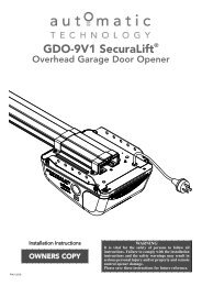
<strong>GDO</strong>-<strong>7V1</strong> <strong>SecuraLift</strong> ®<br />
Overhead Garage Door Opener<br />
Installation Instructions Warning: It is vital for the safety of persons to follow all<br />
instructions. Failure to comply with the installation<br />
instructions and the safety warnings may result in serious<br />
OWNERS COPY<br />
personal injury and/or property and remote control<br />
opener damage.<br />
Please save these instructions for future reference.<br />
P/N 13228
CONTENTS<br />
Safety Precautions---------------------------3<br />
Opener Features------------------------------4<br />
Operating Controls---------------------------5<br />
Kit Contents------------------------------------7<br />
Installation--------------------------------------8<br />
Tube Pipe Assembly---------------------------8<br />
Determine Door Type-------------------------- 9<br />
Mounting - Track Type Door-----------------10<br />
Using inbuilt antivibration brackets---------11<br />
Mounting - Spring Loaded Door------------12<br />
Mounting Door Bracket & Arms-------------13<br />
Easy Access Transmitter---------------------13<br />
Programming the Opener-----------------14<br />
Setting Travel Limits - Control Pane-------14<br />
Setting Travel Limits - Transmitter---------15<br />
Safety Obstruction Force Test----------16<br />
Coding Transmitters------------------------17<br />
Door------------------------------------------------17<br />
Courtesy Light-----------------------------------17<br />
Vacation Mode-----------------------------------17<br />
Pet Mode-----------------------------------------17<br />
Storing Transmitter From Remote Location----18<br />
Erasing Transmitter Codes-------------------18<br />
Accessories------------------------------------19<br />
Photo Electric Beam---------------------------19<br />
Auto-Close---------------------------------------19<br />
Final Set Up------------------------------------20<br />
Courtesy Light Time---------------------------19<br />
Pet Mode Door Height------------------------19<br />
Transmitter Wall Bracket---------------------19<br />
Re-Initializing------------------------------------19<br />
Parameter---------------------------------------21<br />
Door Status Indicators-------------------------21<br />
System Specification-----------------------23<br />
Factory Default Settings----------------------22<br />
Trouble Shooting Guide--------------------24<br />
Maintenance Record------------------------25<br />
Parts List----------------------------------------26<br />
Warranty-----------------------------------------28<br />
Automatic Technology Australia Pty Ltd to the extent that such may be lawfully excluded hereby expressly disclaims all<br />
conditions or warranties, statutory or otherwise which may be implied by laws as conditions or warranties of purchase of<br />
an Automatic Technology Australia Pty Ltd Garage Door Opener. Automatic Technology Australia Pty Ltd hereby further<br />
expressly excludes all or any liability for any injury, damage, cost, expense or claim whatsoever suffered by any person<br />
as a result whether directly or indirectly from failure to install the Automatic Technology Australia Pty Ltd Garage Door<br />
Opener in accordance with these installation instructions.
SAFETY PRECAUTIONS<br />
Warning - It is vital for the safety of persons to follow all instructions. Failure to comply<br />
with the following Safety Rules may result in serious personal injury and/or property damage.<br />
Caution: If your garage has no pedestrian entrance<br />
door, an emergency access device should be<br />
installed. This accessory allows manual operation<br />
of the garage door from outside in case of power<br />
failure.<br />
For ADDITIONAL SAFETY protection we<br />
STRONGLY recommend the fitting of a Photo<br />
Electric Beam. In most countries Photo Electric<br />
Beams are mandatory on all garage doors fitted<br />
with automatic openers. For a small additional<br />
outlay ATA recommends that Photo Electric Beams<br />
be installed with the automatic opener ensuring<br />
additional safety and peace of mind.<br />
DO NOT operate the garage door opener unless<br />
the garage door is in full view and free from objects<br />
such as cars and children/people. Make sure that<br />
the door has finished moving before entering or<br />
leaving the garage.<br />
DO NOT operate the garage door opener when<br />
children/persons are near the door. Children must<br />
be supervised near the garage door at all times<br />
when the door opener is in use. SERIOUS<br />
PERSONAL INJURY and/or property damage can<br />
result from failure to follow this warning.<br />
DO NOT allow children to operate the garage door<br />
opener. SERIOUS PERSONAL INJURY and/or<br />
property damage can result from failure to follow<br />
this warning.<br />
Regularly check to make sure that the SAFETY<br />
OBSTRUCTION FORCE is working correctly, and<br />
is TESTED (by placing a 50mm high object on the<br />
floor) and set as per the Installation Instructions<br />
Manual. Failure to follow the manual could result in<br />
SERIOUS PERSONAL INJURY and/or property<br />
damage. This test must be repeated at regular<br />
intervals and the necessary adjustments made as<br />
required.<br />
DO NOT disengage the door opener to manual operation<br />
with children/persons or any other objects including motor<br />
vehicles within the doorway.<br />
The door opener is not intended for use by young<br />
children or infirm persons without adequate<br />
supervision. Children should be supervised to<br />
ensure that they do not play with the remote<br />
transmitters or the opener.<br />
Keep hands and loose clothing CLEAR of the door<br />
and door opener at all times.<br />
©Copyright 2006 Automatic Technology<br />
- 3 -<br />
The unit should be installed so that it is protected<br />
from the elements. It should not be exposed to<br />
water or rain. It is not to be immersed in water or<br />
sprayed directly by a hose or other water carrying<br />
device.<br />
The garage door must be WELL BALANCED.<br />
Sticking or binding doors must be repaired by a<br />
qualified garage door installer prior to installation of<br />
the opener.<br />
Frequently examine the installation, in particular<br />
cables, springs and mountings for signs of wear,<br />
damage or imbalance. DO NOT use if repair or<br />
adjustment is needed since a fault in the<br />
installation or an incorrectly balanced door may<br />
cause injury. DO NOT attempt to repair the door<br />
yourself as hardware is under extreme tension.<br />
REMOVE OR DISENGAGE all garage door locks<br />
and mechanisms prior to installation of the opener.<br />
Connect the garage door opener to a properly<br />
EARTHED general purpose 240V mains power<br />
outlet installed by a qualified electrical contractor.<br />
DISCONNECT THE POWER CORD from mains power<br />
before making any repairs or removing covers. Only<br />
EXPERIENCED service personnel should remove covers<br />
from the garage door opener.<br />
When using auto close mode, a PHOTO<br />
ELECTRIC BEAM must be fitted correctly and<br />
tested for operation at regular intervals. EXTREME<br />
CAUTION is recommended when using auto close<br />
mode. ALL SAFETY RULES must be followed.<br />
In order for the garage door opener to SENSE an<br />
object obstructing the door way, some FORCE<br />
must be exerted on the object. As a result the<br />
object, door and/or person may suffer DAMAGE or<br />
INJURY.<br />
If the power supply cord is damaged, it MUST be<br />
replaced by an ATA service agent or suitably<br />
qualified person.<br />
Make sure that the door is fully open before driving<br />
in or out of the garage and fully closed before<br />
leaving the driveway.<br />
Make sure that remote controls are kept out of<br />
reach of children.<br />
Install the wall switch or wall mounted transmitter in<br />
a location where it is out of reach of children and<br />
the garage door is visible.
Thank you for purchasing the ATA<br />
<strong>SecuraLift</strong> ® Automatic Garage Door<br />
Opener. This opener is designed to<br />
suit sectional overhead and one<br />
piece tilt up doors. The components<br />
and materials used in this opener<br />
are of the latest technology and<br />
highest quality. Listed below are<br />
some of the many features.<br />
OPERATION<br />
To open or close the door simply<br />
press the hand held transmitter, the<br />
wall mounted transmitter, or optional<br />
wall switch for two seconds. During<br />
an open or close cycle the door can<br />
be stopped by pressing the button<br />
while the door is in motion. The next<br />
actuation will move the door in the<br />
opposite direction.<br />
HOPPING CODE<br />
Every time a transmission is made<br />
from the remote transmitter a new<br />
security code is generated. The<br />
number of possible code<br />
combinations is over 4.29 billion.<br />
This greatly enhances the security<br />
of the system. Code “grabbing” is<br />
made a thing of the past.<br />
S-ALPS (SEMI AUTOMATIC<br />
LIMITS POSITIONING SYSTEM)<br />
The ALPS system does away with<br />
manual adjustment of the doors’<br />
limits position using mechanical<br />
parts, such as cams and micro<br />
switches.<br />
During installation the hand held<br />
transmitter can be programmed to<br />
set the door limits positions.<br />
ANTI TRAVEL ELECTRONIC<br />
BRAKES<br />
opener has anti travel electronic<br />
brake mechanism which ensure the<br />
opener stops the door at exact<br />
location<br />
©Copyright 2006 Automatic Technology<br />
FEATURES<br />
ISS (INTELLIGENT SAFETY<br />
OBSTRUCTION SYSTEM)<br />
While the door is performing a close<br />
cycle, should it hit an obstacle or be<br />
restricted in some manner, it will<br />
automatically reverse. The amount<br />
of force the door should encounter<br />
before reversing is automatically<br />
adjusted by the doors control<br />
system during the initial installation<br />
of the automatic door opener. The<br />
door will also stop if restricted whilst<br />
opening. The Safety Obstruction<br />
Force should be checked at least<br />
once a month. See installation<br />
manual for instructions.<br />
SECURITY CODE STORE<br />
The <strong>SecuraLift</strong> ® Garage Door<br />
Opener uses state of the art<br />
technology in storing your selected<br />
transmitter security code. Up to 24<br />
different transmitters can be stored<br />
in the openers memory.<br />
OVER LOAD INDICATOR<br />
When the maximum opening and<br />
closing capacity of the opener is<br />
exceeded the red and green Limits<br />
LEDs flash alternately to indicate<br />
that an overload has occurred.<br />
AUTO COURTESY LIGHT<br />
The courtesy light on the opener<br />
comes on automatically whenever<br />
the door is activated. The light can<br />
also be switched on and off without<br />
operating the door. This is done by<br />
pressing the button on any hand<br />
held or wall mounted transmitter<br />
which has been stored with the light<br />
code.The light will stay on for<br />
approximately three minutes then<br />
switch off. This time is also<br />
adjustable.<br />
ANTI VIBRATION BRACKETS<br />
opener has inbuilt antivibration<br />
brackets<br />
hang the opener by using anti vibration<br />
brackets where noise is the<br />
problem<br />
- 4 -<br />
VACATION MODE<br />
A hand held transmitter can be<br />
programmed to lock and unlock all<br />
other transmitters that have been<br />
programmed into the openers’<br />
memory. The vacation mode can be<br />
used when the door is left idle for<br />
long periods of time.<br />
PET (PEDESTRIAN) MODE<br />
The hand held transmitter can be<br />
programmed to open the door<br />
partially so that the family pet can<br />
enter and exit the garage at any<br />
time. You may also wish to open the<br />
door to a height suitable only for<br />
pedestrian access. The door opening<br />
position is also programmable.<br />
AUTO CLOSE MODE<br />
The opener can be programmed to<br />
automatically close after an open<br />
cycle. The auto close time is<br />
adjustable. It is compulsory to install<br />
a Photo Electric Beam if this mode<br />
is selected, otherwise the door may<br />
cause personal injury or damage to<br />
property.<br />
PHOTO ELECTRIC BEAM<br />
(OPTIONAL)<br />
The opener has an input for a photo<br />
electric beam to be connected for<br />
extra safety protection and use of<br />
the auto close mode.<br />
MANUAL OPERATION<br />
The opener is equipped with a<br />
unique manual disengaging device.<br />
If the power to the opener is<br />
disrupted for any reason the door<br />
can be put into manual mode by<br />
pulling down on the string handle on<br />
an angle towards the door. This will<br />
allow you to manually open or close<br />
the door. To re-engage the opener<br />
pull the string handle away from the<br />
door.
1. P. E. SHUNT. The shunt has to<br />
be removed when connecting a<br />
Photo Electric Beam.<br />
NOTE: P.E. SHUNT must not be<br />
removed otherwise the opener will<br />
not function correctly. Remove only<br />
when a P.E beam is to be<br />
connected.<br />
PROG INPUT is used for the<br />
connection of the ATA Handheld<br />
Programmer for the purpose of<br />
editing control and receiver<br />
functions.<br />
2. Terminal Block. 24V PWR is used<br />
to power devices such as photo<br />
electric beams.<br />
PE (Input) for photo electric beam<br />
for safety and auto-close function.<br />
LGT (Input) allow hard wired<br />
external trigger for the opener’s<br />
courtesy light.<br />
O/S/C INPUT is used for the<br />
connection of a wired switch<br />
(momentary contact). This switch<br />
can then be used to open, stop or<br />
close the door. Install the wall switch<br />
in a location where the switch is out<br />
of reach of children and the garage<br />
door is visible.<br />
3. SET button (yellow) is used during<br />
the installation phase together<br />
with the Open and Close buttons to<br />
set the door limit positions. The Set<br />
button is also used to re-initialize the<br />
Opener.<br />
4. OPERATE button (Yellow) is<br />
used during installation to test the<br />
open, stop and close cycles for the<br />
opener. The opener has to be<br />
initialized by the Reset button<br />
before the O/S/C button becomes<br />
operable.<br />
©Copyright 2006 Automatic Technology<br />
OPERATING CONTROLS<br />
5. PLUS (+) button (green) is used<br />
during installation to help set the<br />
open limit position. Pressing and<br />
holding this button will move the<br />
door in the open direction.<br />
Movement stops when the button is<br />
released.<br />
NOTE: The open safety obstruction<br />
detection is inoperable whenever<br />
the Open or Close Drive button is<br />
used to move door.<br />
6. OPEN LIMIT LED (green) the<br />
led is very helpful during installation.<br />
It illuminates and flashes when the<br />
door is opening and remains steady<br />
on when the open limit position has<br />
been reached.<br />
7. FORCE MARGIN SET Button<br />
The obstruction force pressure is<br />
set automatically by the opener<br />
during installation. The pressure can<br />
be adjusted manually using the<br />
Force Margin Set button (White).<br />
Holding the Force Margin Set button<br />
and pressing the Plus (+) or Minus<br />
(-) button will increase or decrease<br />
the amount of force. The Force<br />
Margin Set is only ever used if other<br />
environmental factors (wind, etc.)<br />
effect the operations of the<br />
door/opener.<br />
8. LIGHT CODE button (white) is<br />
used for storing or erasing the<br />
transmitter button (code) you wish<br />
to use to switch the courtesy light on<br />
the opener on or off.<br />
9. CODING LED (red) light flashes<br />
when a code is being stored or<br />
when a transmitter button is<br />
pressed.<br />
10. DOOR CODE button (blue) is<br />
used for storing or erasing the<br />
transmitter button you wish to use to<br />
command the door to open, stop or<br />
close.<br />
- 5 -<br />
11. DOOR STATUS LED (Yellow)<br />
12. MINUS (-) button (red) is used<br />
during installation to help set the<br />
close limit position. Pressing and<br />
holding this button will move the<br />
door in the close direction.<br />
Movement stops when the button is<br />
released.<br />
NOTE: The close safety obstruction<br />
detection is inoperable whenever<br />
the Open or Close Drive button is<br />
used to move door.<br />
13. CLOSE LIMIT LED (red) the led<br />
is very helpful during installation. It<br />
illuminates and flashes when the<br />
door is closing and remains steady<br />
on when the close limit position has<br />
been reached.<br />
14. DATUM ADJUST SCREW is<br />
used during limits set up to indicate<br />
the mid point of the door’s travel.<br />
15. AUTO CLOSE TIME button<br />
(White) is used to adjust the auto<br />
close time. While holding in the auto<br />
close button and then pressing the<br />
open button the time is increased.<br />
Each press will increase the time by<br />
5 seconds. Pressing the close<br />
button will decrease the time.<br />
16. ENGAGE/DISENGAGEMENT<br />
CORD when pulled down and<br />
released this will select manual<br />
mode on the opener, particularly<br />
when there is a power failure.<br />
Pulling down and again releasing<br />
will select automatic mode on the<br />
opener. The length of the string is<br />
adjustable.<br />
17. EASY ACCESS TRANSMIT-<br />
TER The “manual release”<br />
engage/disengagement handle has<br />
within its housing a wireless<br />
transmitter. If the button is pressed it<br />
will open, stop or close the garage<br />
door.
1. PE SHUNT, PROG INPUT<br />
2. TERMINAL BLOCK - 24V (Pwr)<br />
0V (Gnd)<br />
PE (Trigger)<br />
LGT (Light Trigger)<br />
OSC (Operate)<br />
Com (Common)<br />
3. SET BUTTON (ORANGE)<br />
4. OPERATE BUTTON (YELLOW)<br />
5. PLUS (+) BUTTON (GREEN)<br />
6. OPEN LIMIT LED (GREEN)<br />
©Copyright 2006 Automatic Technology<br />
OPERATING CONTROLS<br />
3 4 5 6 7<br />
8 9 10 11 12 13 14 15<br />
16<br />
- 6 -<br />
1<br />
7. FORCE MARGIN SET BUTTON<br />
8. LIGHT CODE BUTTON<br />
9. CODE SET LED (RED)<br />
10. DOOR CODE BUTTON (BLUE)<br />
11. DOOR STATUS LED (YELLOW)<br />
12. MINUS (-) BUTTON (RED)<br />
13. CLOSE LIMIT LED (RED)<br />
14. DATUM ADJUST SCREW<br />
15. AUTO CLOSE TIME BUTTON<br />
16. MANUAL RELEASE HANDLE/EASY ACCESS<br />
TRANSMITTER (optional)<br />
2
KIT CONTENTS<br />
ITEM QUANTITY<br />
<strong>GDO</strong>-7 SECURALIFT® DRIVE UNIT-------------------------------------------------------------------------------------------1<br />
SECURACODE ® KEY RING TRANSMITTER PACK---------------------------------------------------------------------1<br />
pack includes two keyring transmitters two batteries and one wall mount bracket for ptx4 transmitter<br />
EASY ACCESS TRANSMITTER - EAT-1 (Not available some models)-----------------------------------------------1<br />
TUBES----------------------------------------------------------------------------------------------------------------------------------5<br />
TUBE INSERTS----------------------------------------------------------------------------------------------------------------------4<br />
PIPE SUPPORT ASSEMBLY-----------------------------------------------------------------------------------------------------1<br />
CHAIN----------------------------------------------------------------------------------------------------------------------------------1<br />
SHUTTLE ASSEMBLY-----------------------------------------------------------------------------------------------1<br />
DOOR ATTACHMENT ARMS-----------------------------------------------------------------------------------------------------2<br />
ACCESSORY PACK-----------------------------------------------------------------------------------------------------------------1<br />
INSTALLATION MANUAL-----------------------------------------------------------------------------------------------------------1<br />
©Copyright 2006 Automatic Technology<br />
- 7 -
IMPORTANT SAFETY INSTRUCTIONS FOR INSTAL-<br />
LATION<br />
Warning: Incorrect installation can lead to severe injury.<br />
Follow ALL installation instructions.<br />
CHECK OPERATION OF DOOR BEFORE BEGINNING<br />
THE INSTALLATION OF THE SECURALIFT® AUTO-<br />
MATIC OPENER CHECK THE OPERATION OF THE<br />
DOOR.<br />
The door must be well balanced and be in a reasonable<br />
operating condition. You should be able to lift the door<br />
smoothly and with little resistance. It should stay open<br />
around 900mm to 1200mm above the floor. The door<br />
should not stick or bind in the guide tracks. The ideal<br />
operational effort in raising or lowering the door should<br />
not exceed a force of 15kg Make sure that all door<br />
locks are either released, or disabled and remove<br />
unnecessary accessories.<br />
STEP 1<br />
Slide shuttle assembly onto tube (one piece only) and<br />
locate it in approximately half way position.<br />
Please note: Arrow on shuttle must point towards<br />
garage door.<br />
To assemble the rest of the tubes, always slide short<br />
insert tube half way into the long tube, then slide other<br />
tube onto remaining portion of insert tubes. Continue<br />
this process with remaining tube until desired length is<br />
achieved.<br />
STEP 2<br />
The opener is supplied with an 8 teeth drive sprocket on<br />
the drive unit. If the opener is to be fitted to a one piece<br />
door without track, exchange the 8 teeth sprocket on<br />
drive unit, with a 7 teeth drive sprocket available as an<br />
option from Automatic Technology.<br />
STEP 3<br />
Attach one end of chain to chain index screw, nearer to<br />
drive unit, using one joint link. (Fig. 1). Proceed to wrap<br />
chain around drive unit sprocket and chain spreader,<br />
then follow along the pipe to the idler wheel on support<br />
pipe assembly, finally attach to the other end of the<br />
chain index screw.<br />
NOTE: Make certain that the teeth of the drive sprocket are<br />
engaged in the chain and that the chain is not twisted.<br />
Make sure that the chain is engaged in the chain spreader<br />
and the idle wheel on the support pipe assembly.<br />
STEP 4<br />
Disengage trolley from chain index by swinging lever<br />
downward (Fig. 2), then slide trolley away from chain<br />
index along pipe track. Loosen locking nuts on chain<br />
index screws. To tighten chain, turn chain index in anticlockwise<br />
direction, looking from support pipe assembly<br />
to drive unit. Do not over-tighten chain as it has to sag<br />
6-12mm. Check before locking screw with locking nuts<br />
that chain is not twisted. When the tension is finalized,<br />
tighten lock nuts at both ends of chain index.<br />
©Copyright 2006 Automatic Technology<br />
TUBE/PIPE ASSEMBLY<br />
- 8 -<br />
SECOND CHAIN<br />
JOINT LINK<br />
LOCKING NUTS<br />
SHUTTLE ASSY<br />
DISENGAGED POSITION<br />
FIRST CHAIN<br />
JOINT LINK<br />
Fig. 1<br />
Fig. 2<br />
ENGAGED POSITION<br />
Fig. 2a
Determine which type of garage door you have as<br />
illustrated below. (Fig. 3 -5).<br />
For a sectional (panel) door on tracks (Fig. 3) proceed<br />
with the installation from Step 5.<br />
For a one piece door on tracks (Fig. 4) proceed with<br />
the installation from Step 5.<br />
For a one piece door without tracks (on springs)<br />
(Fig. 5) proceed with the installation from Step 9.<br />
ONE PIECE DOOR WITH<br />
TRACK<br />
©Copyright 2006 Automatic Technology<br />
DETERMINE THE DOOR TYPE<br />
Fig. 4<br />
- 9 -<br />
DOOR<br />
ONE PIECE DOOR WITHOUT TRACK<br />
Fig. 3<br />
Fig. 5
STEP 5<br />
Open the door and find the highest point of travel of the<br />
top door panel. Using a level, transfer this height to the<br />
wall above the floor (Fig. 6) and mark a line 60mm<br />
above it.<br />
Determine the centre of the location on the wall above<br />
and on top of the door. Then draw two (2) lines 21.5mm<br />
on each side of the door centre. (Fig. 7).<br />
STEP 6<br />
The intersection of line at 21.5mm from door centre and<br />
line 60mm above highest point of travel are centre<br />
points, where holes for mounting of wall bracket should<br />
be drilled. (Fig. 7)<br />
If the wall bracket is mounted onto concrete or brick<br />
wall, use 8mm or 5/16” loxins or dynabolts. If mounting<br />
onto wooden lintel or beam, use wood screw #20 or<br />
equivalent minimum 50mm long.<br />
WARNING: MAKE SURE CONCRETE, BRICK WALL<br />
OR TIMBER LINTELS ARE SOLID AND SOUND SO<br />
AS TO FORM A SECURE MOUNTING PLATFORM.<br />
STEP 7<br />
When the wall bracket is firmly secured in its proper<br />
position, attach the support pipe assembly to wall bracket<br />
with 90 mm long clevis pin and secure with supplied<br />
spring clip, (Fig. 8) leaving drive unit in its packing box<br />
for protection during installation.<br />
STEP 8A (METHOD ONE)<br />
Raise the drive unit from the packing box and support it<br />
in a horizontal position with a step ladder, then open the<br />
garage door. Rest the opener on the open door and use<br />
a scrap piece of wood to bring it to horizontal level. Line<br />
up the track with the centre line on top of the door.<br />
Secure to the ceiling above drive unit mounting holes,<br />
with perforated angle (not supplied). A representative<br />
mounting is shown. (Fig. 9)<br />
Connect angle and drive unit with 2 flat perforated strips<br />
of angle (not supplied) with M8 x 20mm screws, nuts<br />
and washer. Strips should not extend more than 18mm<br />
below centre of drive unit mounting holes. (FIG. 9).<br />
WARNING: THE OPENER MUST BE SECURELY FAS-<br />
TENED TO A STRUCTURAL SUPPORT OF THE<br />
GARAGE. FAILURE TO FASTEN THE OPERATOR<br />
CORRECTLY WILL LEAD TO POSSIBLE OPENER<br />
FAILURE CAUSING SERIOUS PERSONAL INJURY<br />
AND/OR PROPERTY DAMAGE.<br />
©Copyright 2006 Automatic Technology<br />
MOUNTING ON A TRACK TYPE DOOR<br />
- 10 -<br />
Fig. 6<br />
Fig. 7<br />
Fig. 8<br />
Fig. 9
STEP 8B (METHOD TWO)<br />
Raise the drive unit from the packing box and support<br />
it in a horizontal position with a step ladder, then open<br />
the garage door. Rest the opener on the open door<br />
and use a scrap piece of wood to bring it to horizontal<br />
level. Line up the track with the centre line on top of<br />
the door. Secure to the ceiling above drive unit mounting<br />
holes, with perforated angle (not supplied). A representative<br />
mounting is shown. (Fig. 9)<br />
Connect angle and vibration brackets on drive units 2<br />
flat perforated strips of angle (not supplied) Use the<br />
M6 X 16 Flanged Head Bolts (2) and M6 Flanged<br />
Head Nuts (2) and secure the hanger straps to the<br />
anti vibration brackets as per the diagrams .<br />
The brackets may have to be pushed lightly on an<br />
angle to allow the bolts to be fitted.<br />
Strips should not extend more than 18mm below centre<br />
of drive unit mounting holes. (FIG. 9).<br />
.<br />
IMPORTANT:<br />
Make sure that the head of the M6 bolt is facing<br />
the outside edge of the opener so that the<br />
threaded part of the bolt does not come into<br />
contact with the right angled return running<br />
along the edge of the metal chassis..<br />
WARNING: THE OPENER MUST BE SECURELY<br />
FASTENED TO A STRUCTURAL SUPPORT OF THE<br />
GARAGE. FAILURE TO FASTEN THE OPERATOR<br />
CORRECTLY WILL LEAD TO POSSIBLE OPENER<br />
FAILURE CAUSING SERIOUS PERSONAL INJURY<br />
AND/OR PROPERTY DAMAGE<br />
©Copyright 2006 Automatic Technology<br />
USING ANTI VIBRATION BRACKETS<br />
- 11 -
STEP 9<br />
Determine the centre of the door and mark this location<br />
on the wall above and on top of the door. Then draw two<br />
(2) lines 21.5mm on each side of the door. (Fig. 10).<br />
WARNING; MAKE SURE CONCRETE, BRICK WALL<br />
OR TIMBER LINTELS ARE SOLID AND SOUND SO<br />
AS TO FORM A SECURE MOUNTING PLATFORM.<br />
STEP 10<br />
Raise the door to open position. Rest the opener on the<br />
top edge of the door with end of the pipe/tube against<br />
the header wall and drive unit support level with the<br />
lowest point of the open door. (Fig. 11).<br />
Note: Do not slide opener tube/pipe on face of the door<br />
when it is open.<br />
Secure the opener to the ceiling above drive unit<br />
mounting holes, with perforated angle (not supplied).<br />
A representative mounting is shown. (Fig. 9)<br />
Connect angle and drive unit with 2 flat perforated strips<br />
of angle (not supplied) with M8 x 20mm screws, nuts<br />
and washer. Strips should not extend more than 18mm<br />
below centre of drive unit mounting holes. (Fig. 9).<br />
Do not lock screws at this stage.<br />
STEP 11<br />
Close the door slowly. The opener pipe/tube will be elevated<br />
by the top edge of the door as it moves. Stop the<br />
door when it is at its highest point of travel. (Fig. 12)<br />
Allow 25mm additional height for clearance between the<br />
door and the track. Support pipe / tube in this position<br />
and the close the door. (Fig. 12) This will be the height<br />
to mount the wall bracket. Top of door must not touch<br />
tube.<br />
WARNING: THE OPENER MUST BE SECURELY<br />
FASTENED TO A STRUCTURAL SUPPORT OF THE<br />
GARAGE. FAILURE TO FASTEN THE OPERATOR<br />
CORRECTLY WILL LEAD TO POSSIBLE OPENER<br />
FAILURE CAUSING SERIOUS PERSONAL INJURY<br />
AND/OR PROPERTY DAMAGE.<br />
STEP 12<br />
With the centre point of the door located, mark a line<br />
through the centre of the wall bracket onto the header<br />
wall (above the door). Using the bracket as a template<br />
mark a minimum of two holes and drill with appropriate<br />
size bit. If necessary the wall bracket can be anchored<br />
using more than two holes for a more secure fitting.<br />
If the wall bracket is mounted onto concrete or brick<br />
wall, use M8 or 5/16” loxins or dynabolts. If mounted<br />
onto wooden lintel or beam, use wood screws #20 or<br />
equivalent, minimum 50mm long. Attach the wall bracket<br />
to the support pipe assembly with 90mm long clevis pin<br />
(Fig. 13) and securely spring clip.<br />
©Copyright 2006 Automatic Technology<br />
MOUNTING ON A SPRING LOADED DOOR<br />
- 12 -<br />
Fig. 10<br />
Fig. 11<br />
Fig. 12<br />
Fig. 13
STEP 13<br />
The door bracket comes in two parts. The bottom plate<br />
with two mounting holes is used on its own for any one<br />
piece doors. The top plate is placed over the bottom<br />
plate and uses 4 mounting holes for extra strength.<br />
This is used on sectional doors. (See Fig. 14).<br />
Mount the door bracket to the centre line of the door<br />
using M6 or equivalent screws (not supplied)<br />
Alternatively it can be welded on steel doors.<br />
Note: As various types of doors exist, if in doubt about<br />
the strength of the door, reinforcement may need to be<br />
added to the frame or panel where necessary. Damage<br />
to the door panel may occur if the bracket is installed<br />
incorrectly on a panel with insufficient strength. The door<br />
opener warranty does not cover damage caused by the<br />
opener to the door and/or door panel.<br />
STEP 14<br />
Assemble bent and straight arm with screws, and hex<br />
nuts supplied in accessory pack. (Fig. 15) Then connect<br />
assembled arm to the door bracket and the shuttle by<br />
clevis pin and spring clip. shuttle must be in disengage<br />
position. use the bend & straight arm. If installing on a<br />
door with bad wave action, lengthening the arm even<br />
further will assist the door operation by reducing the<br />
wave action.<br />
THE EASY ACCESS TRANSMITTER<br />
The Easy Access Transmitter is prepared ready for use<br />
with the battery pre-installed. Before the transmitter can<br />
be operational, the Transmitter Code has to be stored<br />
into the openers memory. To store the code please follow<br />
the instructions in Step 18.1 on page 16.<br />
REMOVING THE COVER TO REPLACE BATTERY<br />
1. Rotate the cover Clockwise to ‘CLOSE’<br />
2. Rotate the cover Anti-clockwise to ‘OPEN’<br />
REMOVING THE BATTERY<br />
(Battery Type: 3V Lithium Battery CR1220).<br />
Use a non - metallic object (e.g Pen) to remove the<br />
battery. (see Fig. 18)<br />
WARNING<br />
Metallic objects used to remove the battery may<br />
DAMAGE the circuit board or the battery.<br />
REPLACING THE BATTERY<br />
Place one side of the battery into the battery holder,<br />
then press the battery down firmly until it clicks into a flat<br />
position.<br />
Note: The length of the manual release cord is user<br />
adjustable simply by sliding the plastic toggle along the<br />
cord to achieve the desired length. Adjust the length of<br />
the cord so that it can be easily reached by an adult of<br />
average height (ie. less than 1.8m tall).<br />
©Copyright 2006 Automatic Technology<br />
MOUNTING DOOR BRACKET AND ARMS<br />
- 13 -<br />
Fig. 16<br />
Fig. 14<br />
Fig. 15<br />
Fig. 17<br />
Fig. 18
STEP 15<br />
SETTING TRAVEL LIMITS POSITIONS<br />
METHOD ONE: VIA THE CONTROL PANEL<br />
IMPORTANT NOTE: The OPERATE button will not<br />
function until the open and close limits positions are set.<br />
15.1 SETTING DATUM POSITION<br />
1. Move the door manually to engage the shuttle<br />
assembly onto the chain index.<br />
2. Turn power on - the Close Limit LED should be<br />
flashing.<br />
3. Press and hold Minus (-) or Plus (+) button to move<br />
the door to half way open position.<br />
3. Using a small blade screw driver turn the datum<br />
adjust screw slowly until the yellow status LED just<br />
illuminates.<br />
Note: If the status LED is already illuminated when the<br />
door is half way up then turn the datum adjust screw<br />
until the LED goes off then turn back one notch to illuminate<br />
again.<br />
15.2 SETTING LIMITS POSITIONS<br />
NOTE: The door and shuttle must be engaged into the<br />
chain index and should be open approximately half way.<br />
1. Press red Minus (-) button and hold it, the door will<br />
start closing. Release the button once you have<br />
reached your desired closed limit position. (Fig. 21)<br />
2. Press the set button. This action will store into<br />
memory the closed limit position.<br />
3. Press the green Plus (+) button, the door will start<br />
opening. Release the button once you have reached<br />
your desired open limit position.<br />
IMPORTANT WARNING: Please be aware that the<br />
garage door will start closing automatically once step 4<br />
is performed. The door will also automatically re-open<br />
after fully closing with a small pause between the<br />
cycles.<br />
4. Press the Set button. This action will store into<br />
memory the door limit position. The door will now<br />
automatically close to its limit position then fully open<br />
to calculate the safety obstruction forces (ISS).<br />
Please be aware of the above warning.<br />
The opener can now be operated via the OPERATE<br />
Button.<br />
WARNING: DO NOT TURN DATUM ADJUST SCREW<br />
AFTER LIMIT SETTING, OTHERWISE OPENER WILL<br />
NOT FUNCTION CORRECTLY.<br />
15.2 RESETTING DOOR LIMIT POSITIONS<br />
The door travel limit positions can be deleted for new<br />
positions by the following steps below:<br />
1. Press and hold the Close button (Fig. 21) for six (6)<br />
seconds until you hear three beeps and the red<br />
Close Limit LED starts to flash. Release the button.<br />
2. Follow STEPS 15.1 and 15.2 to set new travel limit<br />
positions.<br />
Go to STEP 17 and test the Safety Obstruction<br />
Force.<br />
©Copyright 2006 Automatic Technology<br />
SETTING LIMITS<br />
- 14 -<br />
Fig. 19<br />
Fig. 20<br />
Fig. 21
STEP 16<br />
SETTING TRAVEL LIMIT POSITIONS<br />
METHOD TWO: VIA THE TRANSMITTER<br />
IMPORTANT NOTE: The OPERATE button will not<br />
function until the open and close limits positions are set.<br />
16.1 SETTING DATUM POSITION<br />
1. Move the door manually to engage the shuttle<br />
assembly onto the chain index.<br />
2. Turn power on - the Close Limit LED should be<br />
flashing.<br />
3. Press and hold Minus (-) or Plus (+) button to move<br />
the door to half way open position.<br />
4. Using a small blade screw driver turn the datum<br />
adjust screw slowly until the yellow status LED just<br />
illuminates.<br />
Note: If the status LED is already illuminated when the<br />
door is half way up then turn the datum adjust screw<br />
until the LED goes off then turn back one notch to<br />
illuminate again.<br />
16.2 CODING TRANSMITTER FOR SETTING LIMITS<br />
1. Press and hold the Door Code button (Fig. 24).<br />
2. Press button 1 on the transmitter for two seconds.<br />
Release and pause for two seconds. Press the same<br />
button again on the transmitter for two seconds.<br />
3. Release Door Code button.<br />
16.3 SETTING LIMITS<br />
NOTE: The door and shuttle must be engaged into the<br />
chain index and the door should be open approximately<br />
half way.<br />
1. Press button 4 (Fig. 22), the door will start closing,<br />
release the button once you are 1 to 2 cm from your<br />
desired closed limit position. Press button 3 for two<br />
seconds then release.<br />
2. Press button 4, each press will enable you to fine<br />
inch the door to your desired closed position.<br />
3. Once you are happy with the position press button 2,<br />
this action will store into memory the closed limit<br />
position.<br />
4. Press button 1, the door will start opening. Release<br />
the button once you are 1 to 2 cm from your desired<br />
open limit position. Press button 3 for two seconds<br />
then release.<br />
5. Press button 1. Each press will enable you to fine<br />
inch the door to your desired open position.<br />
IMPORTANT WARNING: Please be aware that the<br />
garage door will start closing automatically once step 6<br />
is performed. The door will also automatically re-open<br />
after fully closing with a small pause between the cycles.<br />
6. Once you are happy with the position press button 2,<br />
this action will store into memory the door limit<br />
position. The door will now automatically close to its<br />
limit position then fully open to calculate the safety<br />
obstruction forces (ISS).<br />
Please be aware of the above warning.<br />
©Copyright 2006 Automatic Technology<br />
SETTING LIMITS<br />
INCH CLOSE<br />
BUTTON 4<br />
INCH OPEN<br />
BUTTON 1<br />
Fig. 22<br />
SET<br />
BUTTON 2<br />
SWITCH<br />
BETWEEN<br />
FAST AND<br />
SLOW INCHING<br />
BUTTON 3<br />
16.4 RESETTING DOOR LIMITS POSITIONS<br />
The door travel limit positions can be deleted for new<br />
positions by the following below:<br />
1. Press and hold the Minus (-) button (Fig. 24) for six (6)<br />
seconds until you hear three beeps and the red Close<br />
Limit LED starts to flash. Release the button.<br />
2. Follow STEP 16.1 and 16.3 to set new travel limit<br />
positions.<br />
Important: Their is no need to re-code the transmitter used<br />
for setting the limit positions. After the limits are set the<br />
transmitter automatically resets to normal operation.<br />
Go to STEP 17 and test the Safety Obstruction Force.<br />
- 15 -<br />
Fig. 23<br />
Fig. 24
STEP 17<br />
SAFETY OBSTRUCTION TEST<br />
Please take care when testing the Safety Obstruction<br />
Force. Excessive force may cause SERIOUS PERSON-<br />
AL INJURY and/or PROPERTY DAMAGE can result<br />
from failure to follow this warning.<br />
17.1 TESTING CLOSE CYCLE<br />
1. Open the door by pressing the Yellow Operate button<br />
(Fig. 25).<br />
2. Place a length of timber approximately 50mm high on<br />
the floor directly under the door (Fig. 25a).<br />
3. Press the Operate button to close door. The door<br />
should strike the object and start to re-open.<br />
17.2 TESTING OPEN CYCLE<br />
1. Close the door by pressing the Operate button.<br />
2. Press again to open the door. When the door<br />
reaches half the opening distance, grab the bottom<br />
rail of the door firmly, the door should stop.<br />
If the door does not reverse readily when closing, or<br />
stop when opening, the force may be excessive and<br />
need adjusting, refer to STEP 17.4.<br />
IMPORTANT WARNING: If the door is closing and is<br />
unable to re-open when obstructed, discontinue use. Do<br />
not use a door with faulty obstruction sensing. Repair<br />
fault and re-test before using.<br />
ADJUSTING SAFETY OBSTRUCTION FORCE<br />
The Safety Obstruction Force is calculated automatically<br />
and set in memory on the <strong>SecuraLift</strong>® opener. It is<br />
usually not necessary to adjust the Safety Obstruction<br />
Force. The only time the force may need to be<br />
increased is due to environmental conditions, for<br />
example, windy or dusty areas, and areas with<br />
extreme temperature changes.<br />
17.3 TO INCREASE FORCE PRESSURE<br />
1. Press and hold the Force Margin Set button (Fig. 25)<br />
2. While holding down the Force Margin button, press<br />
the Plus (+) button. Each press increases the force<br />
margin. The Open Limit LED will flash each time the<br />
Plus button is pressed to indicate an increase in<br />
force. Test the force again as per step 17.1 and 17.2<br />
above. If the Open Limit LED flashes continuously<br />
when the Plus button is being pressed, this indicates<br />
that the maximum force pressure setting has been<br />
reached.<br />
©Copyright 2006 Automatic Technology<br />
SETTING SAFETY OBSTRUCTION FORCE<br />
17.4 TO DECREASE FORCE PRESSURE<br />
1. Press and hold the Force Margin Set button (Fig. 25).<br />
2. While holding down the Force Margin button, press the<br />
Minus (-) button. Each press decreases the force<br />
margin. The Close Limit LED will flash each time the<br />
Minus button is pressed. Test the force again as per<br />
step 17.1 and 17.2 above. If the Close Limit LED flashes<br />
continuously when the Minus button is being pressed,<br />
this indicates that the maximum force pressure setting<br />
has been reached.<br />
17.5 TO RECALL FACTORY SET FORCE<br />
1. While holding down the Force Margin Set button, press<br />
the SET button (Fig. 22) for two seconds.<br />
2. Release both buttons. The default setting should now<br />
be recalled.<br />
- 16 -<br />
WOOD (50MM HIGH)<br />
Fig. 25<br />
Fig. 26
STEP 18<br />
SETTING TRANSMITTERS CODES<br />
Make sure to connect the battery to the transmitters.<br />
The memory in the openers receiver can store up to 24<br />
different remote control transmitters.<br />
18.1 STORING THE TRANSMITTERS CODE<br />
1. Press and hold the Door Code button (Fig. 26).<br />
2. Press the button (one of four) on the transmitter you<br />
would like to use to control the door for two seconds,<br />
pause for two seconds. Press the same button again<br />
on the transmitter for two seconds.<br />
3. Release the Door Code button.<br />
4. Press the transmitter button to test if it operates<br />
the door.<br />
18.2. SETTING THE TRANSMITTER<br />
TO OPERATE THE COURTESY LIGHT<br />
The transmitter can be programmed to operate the courtesy<br />
light on the door opener.<br />
1. Press and hold Light Code button (Fig. 26).<br />
2. Press the button on the transmitter you would like to<br />
use to switch on the light for two seconds, pause for<br />
two seconds. Press the same button again on the<br />
transmitter for two seconds.<br />
3. Release all buttons to store the transmitter in memory.<br />
4. Press the transmitter button to test if it switches on<br />
the light.<br />
18.3. SETTING THE TRANSMITTER TO OPERATE<br />
PET (PEDESTRIAN) MODE<br />
1. Press and hold Door Code button and the Close<br />
button (Fig. 26).<br />
2. Press the button on the transmitter you would like to<br />
use to control pedestrian mode for two seconds,<br />
pause for two seconds. Press the same button again<br />
on the transmitter for two seconds.<br />
3. Release all buttons to store the transmitter in memory.<br />
4. Press the transmitter button to test if it operates the<br />
pedestrian mode.<br />
To change the default pet (pedestrian) door opening<br />
position, refer step 24 on page 19.<br />
18.4. SETTING THE TRANSMITTER TO OPERATE<br />
VACATION MODE<br />
1. Press and hold Light Code button and the Close<br />
button (Fig. 26).<br />
2. Press the button on the transmitter you would like to<br />
use to control vacation mode for two seconds, pause<br />
for two seconds. Press the same button again on<br />
the transmitter for two seconds.<br />
3. Release all buttons to store the transmitter in memory.<br />
4. To test, press and hold the transmitter button set for<br />
vacation mode for five seconds to set Vacation Mode.<br />
To reset Vacation Mode press the same button for two<br />
seconds. Please note that when vacation mode is<br />
activated all stored transmitters will be locked out. This<br />
mode can only be deactivated by a transmitter which<br />
has been stored to activate this mode.<br />
©Copyright 2006 Automatic Technology<br />
CODING TRANSMITTERS<br />
- 17 -<br />
Fig. 26
STEP 19<br />
STORING TRANSMITTER(S) FROM A REMOTE<br />
LOCATION<br />
Using this method you don’t need to have access to the<br />
control panel on the Door Opener. However, you do<br />
need a transmitter that is pre coded to the controller’s<br />
receiver.<br />
IMPORTANT NOTE: The Door or Courtesy Light must<br />
be activated when the step below is performed. The<br />
moving Door or Light switching on is to confirm from a<br />
remote location that, the correct button was pressed,<br />
and the transmitter is in range of the Opener.<br />
1. Take any pre-coded transmitter. Press the button for<br />
the function you require until the door is activated<br />
and release.<br />
2. Then using a small needle press and hold firmly for<br />
two seconds through the Coding Hole (Fig. 27)<br />
3. Within 10 seconds take the additional transmitter you<br />
wish to code.<br />
4. Press the button (one of four) on that transmitter you<br />
would like to use to control the door for two seconds,<br />
pause for two seconds. Press the same button again<br />
on the transmitter for two seconds, the button should<br />
now be recorded.<br />
5. Wait for 10 seconds and then press the recorded<br />
transmitter button to see if it operates the door.<br />
20. DELETING PROGRAMMED CODES<br />
20.1 DELETING A STORED TRANSMITTER CODE<br />
1. Select the transmitter you want to delete.<br />
2. Press and hold the Door Code button (Fig. 28).<br />
3. Press the transmitter button you would like to delete<br />
for two seconds. Pause for two seconds. Press the<br />
transmitter button again for two seconds.<br />
4. Release the Door Code button. The code should now<br />
be deleted. Confirm this by pressing the transmitter<br />
button, the door should not respond.<br />
20.2 DELETING ALL STORED TRANSMITTER<br />
CODES<br />
1. Turn the Power Off to the Opener.<br />
2. Press and hold the Door Code button (Fig. 28).<br />
3. Turn the Power On again, while holding the Door<br />
Code button. The Open Limit, Close Limit and Door<br />
Status LED’s will illuminate for about five seconds.<br />
These LED’s will turn Off and the Coding LED will<br />
illuminate. Release the Door Code button. All the<br />
stored codes including the Courtesy Light codes<br />
should now be deleted. Confirm this by trying to<br />
operate the door by pressing the transmitters<br />
previously used to control the door, the door should<br />
not respond.<br />
©Copyright 2006 Automatic Technology<br />
CODING TRANSMITTERS<br />
- 18 -<br />
Fig. 27<br />
Fig. 28
21. FITTING THE SAFETY PHOTO<br />
ELECTRIC BEAM SENSOR (OPTIONAL)<br />
Locate the Photo Electric Beam (P.E.) normally closed<br />
contact type in a strategic location within doorway. We<br />
recommend 150mm above the floor level and as close<br />
as possible to the door opening, inside the garage.<br />
Remove shunt from P.E connector (Fig. 29) and connect<br />
the wires from the P.E. wiring harness to terminal block<br />
(Fig. 30). The wiring diagram is for Model PHBE (Order<br />
Code 90214).<br />
Make sure to align the beams correctly. Follow the<br />
manual supplied with the Photo Electric Beam.<br />
WARNING: When using Auto Close Mode and P.E.<br />
beams, the doorway must be clear of all obstructions<br />
and persons at all times. The location of the beam and<br />
manner in which it is installed might not give safety protection<br />
at all times. Check to make sure that the height<br />
of the beam and type used give maximum protection<br />
possible.<br />
22. SETTING OF AUTO CLOSE TIME<br />
IMPORTANT NOTICE: IT IS COMPULSORY TO<br />
INSTALL A PHOTO ELECTRIC BEAM BEFORE<br />
USING THE AUTO CLOSE MODE.<br />
The Auto Close timer will only start after the Photo<br />
Electric Beams (P.E.) path is broken and the auto close<br />
time has been set. If the P.E. path is not broken the door<br />
will remain open till the path is broken. If the Door<br />
Opener incurs an obstruction (not from the P.E.) while<br />
closing the door will re-open and not auto close until the<br />
part of the P.E. beam is broken again.<br />
SETTING AUTO CLOSE TIME<br />
1. Press and hold the Auto Close Time button (Fig. 31).<br />
2. While holding in the Auto Close Time button, press<br />
the Plus (+) button. Each press of this button will<br />
add one second to the auto close delay time.<br />
3. To decrease the delay time follow Step 1 and press<br />
the Minus (-) button. Each press will deduct one<br />
second from the auto close time.<br />
4. Press the Operate button or transmitter to open the<br />
door. When the door is fully opened the Open Limit<br />
green LED will flash to indicate that the auto close<br />
mode is in operation. Break the path of the P.E.<br />
Beam momentarily, this will initialize the auto close<br />
mode. When the door reaches the fully opened<br />
position, the door will pause for the set auto close<br />
time and start to auto close.<br />
©Copyright 2006 Automatic Technology<br />
P.E. BEAM AND AUTO CLOSE<br />
- 19 -<br />
REMOVE PE SHUNT<br />
Fig. 29<br />
Fig. 30<br />
Fig. 31
23. SETTING OF COURTESY LIGHT TIME<br />
The preset courtesy light time on the door opener is<br />
3 minutes. This time can be changed by the following:<br />
1. Press in and hold both the Auto Close Time button<br />
and Force Margin Set button (Fig. 32).<br />
2. While holding in the two buttons, press the Plus (+)<br />
button. Each press of the button will add 10 seconds<br />
to the light time.<br />
3. To decrease the time follow Step 1 and press the<br />
Minus (-) button. Each press will deduct 10 seconds<br />
from the light time.<br />
4. To recall the factory set default light time press in and<br />
hold together the Auto Close Time button, the Force<br />
Margin Set button and the Set button for about<br />
2 seconds. Release all buttons, the factory set<br />
default of 3 minutes will be recalled.<br />
24. SETTING THE PET MODE DOOR OPENING<br />
POSITION.<br />
The default PET (Pedestrian) position is factory preset<br />
to a predetermined height. The PET mode status is<br />
indicated by both the Open and Close Limit LED’s being<br />
illuminated. The default position can be changed by the<br />
following:<br />
1. Make sure the door is in the closed position. Press<br />
and hold the Plus (+) button for six (6) seconds<br />
(Fig. 32), you should hear three beeps and the Open<br />
and Close LEDs will flash rapidly.<br />
2. Press the Plus (+) or Minus (-) button (Fig. 32) to<br />
move the door to your required new pet open door<br />
position.<br />
3. Press the Set button (Fig. 32) to record the new<br />
position.<br />
The Pet mode is activated from a transmitter button<br />
coded to that function. When activated the door drives to<br />
the preset position from either above or below. If the Pet<br />
button is pressed while the door is moving the door will<br />
be stopped. If the Pet button is pressed when the door<br />
is in the Pet position, then the door will be closed. No<br />
auto close is enabled.<br />
25. INSTALLATION OF WALL MOUNTED<br />
TRANSMITTER HOLDER<br />
1. Mount the holder in a location out of reach of children<br />
and convenient to the customer. (Fig 33). Make sure<br />
the door is visible from this location.<br />
2. The transmitter can be easily clipped in and removed<br />
from the holder as required.<br />
3. To set the transmitter codes refer to Step 18 on<br />
Page 16.<br />
26. RE-INITIALIZING THE OPENER<br />
To re-initialize the opener press and hold the Set Button<br />
for two (2) seconds, the beeper will sound once. The<br />
door will start to move and re-calculate force margins.<br />
The door can move between the open and close limit<br />
positions up to four (4) times (depending on the position<br />
of the door and the power up condition). A single beep<br />
will be heard once the initialization is complete. The<br />
door is now ready for use.<br />
©Copyright 2006 Automatic Technology<br />
FINAL SET UP<br />
- 20 -<br />
Fig. 32<br />
Fig. 33
DOOR OPENER STATE<br />
©Copyright 2006 Automatic Technology<br />
PARAMETERS<br />
DOOR STATUS INDICATORS<br />
OPEN LED<br />
GREEN<br />
OPEN ON<br />
DOOR STATUS INDICATORS<br />
- 21 -<br />
CLOSE LED<br />
RED<br />
CLOSE ON<br />
OPENING FLASHING<br />
CLOSING FLASHING<br />
DOOR TRAVEL STOPPED FLASHING FLASHING<br />
DOOR OBSTRUCTED WHEN OPENING FLASHING<br />
DOOR OBSTRUCTED WHEN CLOSING FLASHING<br />
OPENER OVERLOADED<br />
DOOR IN OPEN POSITION WITH<br />
AUTO CLOSE MODE SELECTED<br />
MAINS POWER INTERRUPTED<br />
ALTERNATING<br />
FLASHES<br />
ONE SECOND<br />
FLASHES<br />
RAPID<br />
FLASHES<br />
BUTTON FUNCTION<br />
ALTERNATING<br />
FLASHES<br />
Operate Opens/Stops/Closes the door<br />
DOOR STATUS<br />
LED YELLOW<br />
Door Code Codes a transmitter button for Operate function<br />
Light Code Codes a transmitter button for light function<br />
Door Code & Minus (-) Codes a transmitter button for pet (pedestrian) function<br />
Light Code & Minus (-) Codes a transmitter button for vacation function<br />
Force Margin Set & Pus (+) Increases the obstruction force margin setting<br />
Force Margin Set & Minus (-) Decreases the obstruction force margin setting<br />
BEEPER<br />
BEEPS WHILE<br />
DOOR IS MOVING<br />
Force Margin Set (then) Set Reloads the factory set default obstruction force margin setting<br />
Auto Close Time (then) Plus (+) Increases the auto close delay time<br />
Auto Close Time (then) Minus (-) Decreases the auto close delay time<br />
Auto Close Time (then) Set Reloads the factory set default auto close delay time<br />
Force Margin Set & Auto Close Time (then) Plus (+) Each press of the open button increases the light time by 10 secs.<br />
Force Margin Set & Auto Close Time (then) Minus (-) Each press of the open button decreases the light time by 10 secs.<br />
Force Margin Set & Auto Close Time (then) Set Reloads the factory set default light time<br />
Minus (-) (for 6 secs.) Clears the door limits set positions. Limits then need to be reset.<br />
Set & Close (for 2 secs.) Enters pet (pedestrian) position mode.<br />
Set (the power on) and hold until all LEDs are off Deletes control parameters excluding transmitter storage memory.<br />
Door Code (the power on) and hold until all LEDs are off Deletes all transmitter storage memory.<br />
Set & Door Code (the power on) and hold until all LEDs are off Deletes all control parameters and transmitter storage memory.<br />
Set Re initialises opener obstruction force margin.
©Copyright 2006 Automatic Technology<br />
DEFAULT SETTINGS AND SPECIFICATIONS<br />
FACTORY DEFAULT SETTINGS<br />
DEFAULT STEP MAXIMUM<br />
MAXIMUM MOTOR RUN TIME 30 Secs. — —<br />
COURTESY LIGHT TIME 4 Mins 10 Secs. 10 Mins.<br />
OBSTRUCTION FORCE MARGIN 3 1 27<br />
AUTO CLOSE TIME 0 Secs. 5 Secs. 4 Mins.<br />
- 22 -
Maximum residential overhead<br />
garage door area<br />
16.5m2<br />
Door Load Rated Load: 150N (15kg)<br />
Push pull force 600N (60kg)<br />
Short term peak load 700N (70kg)<br />
Supply Voltage 230 - 240 V AC 50Hz<br />
Motor Type 1/3 H.P. (AC) Alternating Current<br />
Current Max. 5A<br />
Globe Edison (screw mount) 240V 60W Rough Service (or construction type)<br />
Limit Adjustment Electronic - semi-automatic<br />
Force Control Electronic - fully automatic. Can be adjusted for environmental reasons<br />
Transmitter Frequency 433.92MHz<br />
Powerhead Weight 7.75kg<br />
Max. Opener Run Time 30 Secs.<br />
Transmitter Code Storage Capacity 24 x 4 Button Transmitters<br />
Code Type Hopping Code<br />
No. of Code Combinations Over 4.29 Billion Random Codes<br />
PTX-4 Transmitter Battery A23 12Volt Alkaline<br />
SYSTEM SPECIFICATIONS<br />
EAT-1 Transmitter Battery CR1220 Lithium 3 Volts<br />
Note:<br />
1. The maximum door opening on which the <strong>SecuraLift</strong> ® can be installed is 6000mm wide by 2400mm high or with an<br />
optional extension kit - 5500mm wide by 2700mm high. Door surface area must not exceed 15m2. The door must be<br />
well balanced. A person should be able to lift the door up manually with very little effort in case of an emergency.<br />
2. Intermittent operations may occur in areas which experience very strong winds. Strong wind puts extra pressure on<br />
the door and tracks which may in turn trigger the safety obstruction detection system intermittently.<br />
©Copyright 2006 Automatic Technology<br />
- 23 -
TROUBLE SHOOTING<br />
SYMPTOM POSSIBLE CAUSE REMEDY<br />
Door will not operate. Mains power not switched on.<br />
Door is obstructed.<br />
Door is locked or motor jammed.<br />
Door tracks/hardware damaged.<br />
Door starts to close but automatically<br />
reverses to open position.<br />
Door operates from drive unit (OPERATE)<br />
button but not from transmitter.*<br />
See note.<br />
*Please Note: Some areas may be prone to excessive radio interference brought on by devices such as cordless<br />
telephones, wireless stereo headphones and baby monitors. It is possible that these devices could cause a degree of<br />
interference such as to greatly reduce the range of the transmitter. In such an instance please contact your ATA dealer<br />
for an alternative frequency replacement kit. As this is not a warrantable situation but an environmental issue charges<br />
may apply for the change-over.<br />
©Copyright 2006 Automatic Technology<br />
The opener is in “Vacation Mode”<br />
Adverse weather conditions (wind or cold)<br />
causing door to stiffen and become tight in<br />
the tracks.<br />
Possible obstruction in the doorway.<br />
Transmitter code not stored in memory.<br />
Flat Battery.<br />
Broken battery lead inside transmitter.<br />
- 24 -<br />
Switch on mains power.<br />
Remove obstruction.<br />
Unlock door or remove jam.<br />
Door requires service/repair by qualified<br />
technician.<br />
Turn off “Vacation Mode”<br />
Increase force margin setting and/or<br />
re-initialize the door.<br />
See Step 17 on page 15.<br />
Remove obstruction.<br />
Code transmitter in to openers memory.<br />
Refer Step 18.1 on page 16.<br />
Replace battery - A23 Alkaline 12V.<br />
Send transmitter to installer or ATA for<br />
repair.<br />
Door will not close fully. Door limits positions need to be reset. Reset limits positions. Step 15 Page 13.<br />
Door will not open fully. Door limits positions need to be reset. Reset limits positions. Step 15 Page 13.<br />
Courtesy light not working. Globe blown. Replace globe - Edison Type 240V 60W.<br />
Globe keeps blowing. Incorrect globe voltage - must be 240V AC. Replace globe - Edison Type 240V 60W.<br />
Auto close not working. PE Beam or wiring faulty<br />
PE Beam not aligned correctly.<br />
PE Beam is obstructed.<br />
Door obstructed when closing.<br />
Auto close time not set.<br />
Auto close mode not set.<br />
Repair PE Beam or replace wiring.<br />
Re-align optics.<br />
Remove obstruction from the path of PE.<br />
Remove obstruction.<br />
See Step 22 on page 18.<br />
See Step 22 on page 18.
MAINTENANCE RECORD<br />
MAINTENANCE RECORD<br />
Record any maintenance in the following table to assist in any warranty service.<br />
DATE MAINTENANCE PERFORMED BY SIGNATURE AMOUNT INV. No.<br />
©Copyright 2006 Automatic Technology<br />
- 25 -
Item Order<br />
No. Description Code<br />
1 BASE PLATE SUB ASSEMBLY-------------------02152<br />
2 BUSH 127ID 18---------------------------------------04261<br />
3 AC MOTOR IT 0.24kW------------------------------14423<br />
4 SEL-LOCK PIN SPRING ACP M4x20-----------02590<br />
5 LABEL THERMALLY PROTECTED--------------13620<br />
6 COVER PROTECTION------------------------------13790<br />
7 HEX NUT W/INT TOOTH WASHER M5--------10881<br />
8 LABEL 240V 60 WATT <strong>GDO</strong>-2--------------------13630<br />
9 MOTOR BRACKET <strong>GDO</strong>-7------------------------13776<br />
10 BUSH 127 17-10--------------------------------------04271<br />
11 BUSH ID 10x10----------------------------------------04290<br />
12 WORM 2520 2S-ST-----------------------------------04932<br />
13 CHOPPER WHEEL <strong>GDO</strong>-7-------------------------04951<br />
14 CHOPPER CLIP---------------------------------------04960<br />
15 BOARD HOUSING SUB ASSY--------------------01586<br />
16 CONTROL BOARD CB-18 V1---------------------01020<br />
17 BOARD SHIELD---------------------------------------14053<br />
18 TAPTITE SCREW ‘P’ M4x8-------------------------10580<br />
19 POWER CORD 1.5M W 2PIN+1 RING----------14150<br />
20 EASY ACCESS TRANSMITTER PACK---------01236<br />
21 CONTROLS LID---------------------------------------05108<br />
22 CORD GRIP GROMMET SBR5-2----------------05605<br />
23 LAMP HOLDER LS 204-1-------------------------05761<br />
24 TERMINAL BLOCK 500/02DS 2 POS-----------05421<br />
25 HARNESS ASSY CB-7 (NOT SHOWN)--------14441<br />
26 CAP POLYFILM 0.1 uF K X2 275 VAC---------07575<br />
27 TERMINAL BLOCK SHIELD-----------------------14056<br />
28 DRIVE SHAFT Q-C-----------------------------------04542<br />
29 HELICAL GEAR 34209------------------------------04941<br />
30 SPROCKET 8T OCTAGONAL---------------------04685<br />
31 CAP MOTOR 15.0 uF 44O VAC 3k Hr----------14402<br />
32 CHAIN IDLE WHEEL---------------------------------02962<br />
33 SNAP PIN SSP 8 ZNU 31080--------------------10720<br />
34 SNAP PIN SSP 12 ZNU 31120-------------------10730<br />
35 CABLE CLAMP ACC-15 (3/16”)-------------------11750<br />
36 GLOBE 250V 60W------------------------------------14120<br />
37 PAN HEAD SCREW W/WASHER M5x10------10281<br />
©Copyright 2006 Automatic Technology<br />
PARTS LIST<br />
WHEN ORDERING SPARE PARTS PLEASE QUOTE THE ORDER CODE<br />
NUMBER TO YOUR INSTALLER/DEALER<br />
Item Order<br />
No. Description Code<br />
38 PAN SERRATION HEAD SCREW M4x12-------------10380<br />
39 PAN HEAD SCREW W/WASHER M4x10-------------10340<br />
40 PAN HEAD SCREW M3x14-------------------------------10360<br />
41 INTERNAL TOOTH LOCK WASHER I.D.3------------11150<br />
42 COVER ASSY <strong>GDO</strong>-7--------------------------------------01599<br />
43 LIGHT DIFFUSER-------------------------------------------13902<br />
44 TAPTITE SCREW ‘P’ BLACK M3.5x6------------------10542<br />
45 PAN HEAD SCREW W/WASHER M4x8---------------10320<br />
46 CHAIN JOINT LINK------------------------------------------02950<br />
47 SHUTTLE ASSEMBLY--------------------------------------00273<br />
48 SECURA PTX-4 & WALL SWITCH PACK--------------01220<br />
49 TRANSMITTER GREY BUTTONS PTX-4-------------01210<br />
50 TRANSMITTER RED BUTTONS PTX-4---------------01211<br />
51 PTX HOLDER-------------------------------------------------05196<br />
52 ALKALINE BATTERY A23 12V---------------------------13030<br />
53 PLASTIC WALL PLUG PACK-----------------------------01479<br />
54 CLEVIS PIN DIAMETER 8--------------------------------02550<br />
55 PIN---------------------------------------------------------------05790<br />
56 HEX HEAD SCREW M8x25-------------------------------10110<br />
57 HEX SERRATION FLANGE NUT M8-------------------10148<br />
58 WALL BRACKET---------------------------------------------02521<br />
59 DOOR BRACKET--------------------------------------------02511<br />
60 DOOR BRACKET LOCATOR-----------------------------02515<br />
61 SUPPORT PIPE CX ASSEMBLY-------------------------00292<br />
62 CHAIN 1/2”x1/8” (499 LINKS) W/2 CL------------------03000<br />
63 TUBE 338605--------------------------------------------------13801<br />
64 INDEX TUBE 338605----------------------------------------13811<br />
65 TUBE-INSERT 2970-----------------------------------------13830<br />
66 BENT ARM-----------------------------------------------------02800<br />
67 STRAIGHT ARM----------------------------------------------02790<br />
68 RATCHET TIMING ASSEMBLY---------------------------01737<br />
69 SENSOR ASSEMBLY---------------------------------------01689<br />
70 TAPTITE SCREW ‘P’ M3x12------------------------------10553<br />
71 VIBRATION ISOLATOR-------------------------------------02530<br />
72 PAN HEAD SCREW W/WASHER M4x10-------------10340<br />
73 SHOULDER SCREW 5-M4x9L---------------------------10601<br />
74 GROMMET 5.2x8.0x4.5-------------------------------------05604<br />
- 26 -
©Copyright 2006 Automatic Technology<br />
PARTS LIST<br />
- 27 -
WARRANTY AND EXCLUSION OF LIABILITY<br />
1. This warranty is an addition to any non-excludable conditions or warranties that are implied into this contract by<br />
relevant statute, including the Trade Practices Act 1974 (Cth).<br />
2. Subject to all of the matters set out below, Automatic Technology Australia Pty Ltd (“ATA”) warrants:<br />
(a) swing and sliding gate opener drive units for twelve (12) months or 2500 cycles, whichever occurs first;<br />
(b) roll-up and overhead door opener drive units for twenty four (24) months or 5000 cycles, whichever occurs first; and<br />
(c) all components and accessories for twelve (12) months,<br />
from the date of purchase (specified in the sales docket receipt) as free of any defects in material and workmanship.<br />
3. This warranty applies only where the purchaser:<br />
(a) immediately notifies ATA or the retailer of the alleged defect;<br />
(b) returns the product to the retailer; and<br />
(c) presents the relevant sales docket and this warranty document to the retailer to confirm the date of purchase.<br />
4. Except for this warranty, ATA gives no warranties of any kind whatsoever (whether express or implied), in relation to<br />
the product, and all warranties of whatsoever kind relating to the product are, to the extent permissible by statute,<br />
hereby excluded.<br />
5. To the extent permissible by statute, ATA disclaims any liability of whatsoever nature in respect of any claim or demand<br />
for loss or damage which arises out of:<br />
a) accidental damage to or normal wear and tear to the product or to the product’s components;<br />
b) any cost relating to damage resulting from wear and tear;<br />
c) blown fuses, loss or damage caused by electrical surges, power surges or power spikes;<br />
d) loss or damage due to theft, fire, flood, rain, water, lightning, storms or any other acts of God;<br />
e) maximum continuous operating time exceeding one (1) minute in ten (10);<br />
f) maximum operating force exceeding 15Kg (150N) when moving the door or gate manually to the open or<br />
closed position;<br />
g) door surface area and/or weight exceeding 15m2 and 100Kg respectively;<br />
h) residential gate weight exceeding 400Kg;<br />
i) door or gate not in safe and correct working order and condition;<br />
j) evidence of unauthorised repairs;<br />
k) any cost relating to damage caused by misuse, negligence or failure to maintain the equipment in a proper working<br />
order as per clauses (d) through (i);<br />
l) installation, adjustment or use which is not in accordance with the instructions set out in installation instruction manual<br />
m) attempted or complete modification or repairs to the product carried out by a person who is not authorised or<br />
has not been trained by ATA to carry out such modification or repairs;<br />
n) faulty or unsuitable wiring of structure to which the product is fixed or connected;<br />
o) radio (including citizen band transmission) or any electrical interference;<br />
p) damage caused by insects;<br />
q) loss or damage to any property whatsoever or any loss or expense whatsoever resulting or arising there from or<br />
any consequential loss;<br />
r) any cost or expense arising due to manufacturer recall of any product;<br />
s) any cost or expense due to negligence of the approved service provider;<br />
t) installation of a residential garage door or gate opener in a commercial or industrial situation or a non-single<br />
residential dwelling.<br />
6. ATA’s liability under this warranty is limited, at ATA’s absolute option, to replacing or repairing the product which ATA,<br />
in its unfettered opinion, considers to be defective either in material and/or workmanship or to credit the dealer with the<br />
price at which the product was purchased by the dealer.<br />
7. This warranty does not extend to cover labour for installation.<br />
8. This warranty is limited to Return-to-Base (RTB) repair and does not cover labour for on-site attendance.<br />
9. This warranty is void if the Product is not returned to the manufacturer in original or suitably secure packaging.<br />
10. This warranty is only applicable for repairs to the product carried out within Australia.<br />
11. This warranty does not cover consumable items including globes, batteries and fuses.<br />
12. This warranty is not transferable.<br />
13. Where the Product is retailed by any person other than ATA, except for the warranty set out above, such person has<br />
no authority from ATA to give any warranty or guarantee on ATA’s behalf in addition to the warranty set out above.<br />
Notes:<br />
1. One (1) cycle = one (1) open and one (1) close action of the door or gate.<br />
2. This warranty is to be read in conjunction with the owner’s copy of the installation instruction manual.<br />
AUTOMATIC TECHNOLOGY PTY LTD<br />
ABN 11 007 125 368<br />
6-8 Fiveways Bvd, Keysborough, Victoria, Australia 3173<br />
Tel: +61 3 9791 0200 Fax: +61 3 9791 0250<br />
Web: www.ata-aust.com.au Email: sales@ata-aust.com.au<br />
©October 2006 Automatic Technology Pty Ltd. All Rights Reserved. SecuraCode® and <strong>SecuraLift</strong>® are registered trademarks of Automatic Technology.<br />
In an ongoing commitment to product quality ATA reserve the right to change specifications without notice. E&OE. Printed For Export<br />
P/N: 13228