Sectional and Tilt Garage Door Opener Installation and ... - Merlin
Sectional and Tilt Garage Door Opener Installation and ... - Merlin
Sectional and Tilt Garage Door Opener Installation and ... - Merlin

You also want an ePaper? Increase the reach of your titles
YUMPU automatically turns print PDFs into web optimized ePapers that Google loves.
www.chamberlainanz.com<br />
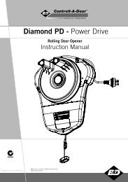
MT230<br />
<strong>Sectional</strong> <strong>and</strong> <strong>Tilt</strong> <strong>Garage</strong> <strong>Door</strong> <strong>Opener</strong><br />
<strong>Installation</strong> <strong>and</strong> Operating Instructions<br />
Owners Copy: Please keep these instructions for future reference<br />
This manual contains IMPORTANT SAFETY information.<br />
DO NOT PROCEED WITH THE INSTALLATION BEFORE READING THOROUGHLY.<br />
N2966
START BY READING THESE IMPORTANT SAFETY INSTRUCTIONS<br />
WARNING<br />
• Failure to comply with the following instructions may result in serious personal injury or property damage.<br />
• Read <strong>and</strong> follow all instructions carefully.<br />
• The garage door opener is designed <strong>and</strong> tested to offer safe service provided it is installed <strong>and</strong><br />
operated in strict accordance with the instructions in this manual.<br />
These safety alert symbols mean WARNING : A possible risk to personal safety or<br />
property damage exists.<br />
Keep garage door balanced. Do not let the<br />
garage door opener compensate for a binding or<br />
sticking garage door. Sticking, binding or unbalanced<br />
doors must be repaired before installing this<br />
opener.<br />
Do not wear rings, watches or loose clothing<br />
while installing or servicing a garage door opener.<br />
Frequently examine the door installation, in<br />
particular cable, springs <strong>and</strong> mountings for signs<br />
of wear, damage or imbalance. Do not use if repair<br />
or adjustment is needed since springs <strong>and</strong> hardware<br />
are under extreme tension <strong>and</strong> a fault can<br />
cause serious personal injury.<br />
To avoid serious personal injury from entanglement,<br />
remove all ropes, chains <strong>and</strong> locks connected<br />
to the garage door before installing the<br />
door opener.<br />
<strong>Installation</strong> <strong>and</strong> wiring must be in compliance<br />
with your local building <strong>and</strong> electrical codes.<br />
The safety reverse system test is very important.<br />
Your garage door MUST reverse on contact<br />
with a 40mm obstacle placed on the floor. Failure<br />
to properly adjust the opener may result in serious<br />
personal injury from a closing garage door.<br />
Repeat the test once a month <strong>and</strong> make any<br />
necessary adjustments.<br />
This opener should not be installed in a damp<br />
or wet space exposed to weather.<br />
This appliance is not intended for use by persons<br />
(including children) with reduced physical, sensory<br />
or mental capabilities, or lack of experience <strong>and</strong><br />
knowledge, unless they have been given supervision<br />
or instruction concerning use of the appliance<br />
by a person responsible for their safety.<br />
Warning: If your garage has no service entrance door, a CM1702 outside quick release must be installed.<br />
This accessory allows manual operation of the garage door from outside in case of power failure.<br />
CONTENTS PAGE<br />
SAFETY INSTRUCTIONS . . . . . . . .2<br />
DOOR TYPES . . . . . . . . . . . . . . . . .3<br />
TOOLS REQUIRED . . . . . . . . . . . .3<br />
HARDWARE PROVIDED . . . . . . . .3<br />
BEFORE YOU BEGIN . . . . . . . . . . .4<br />
COMPLETED INSTALLATION . . . .4<br />
ASSEMBLY . . . . . . . . . . . . . . . . .4-5<br />
INSTALLATION . . . . . . . . . . . . .6-10<br />
ADJUSTMENT . . . . . . . . . . . . .11-12<br />
SAFETY REVERSE SYSTEM . . . .12<br />
INSTALL IR SAFETY BEAMS . . . .13<br />
2<br />
The Protector System TM must be used for all<br />
installations where the closing force as<br />
measured on the bottom of the door is over<br />
400N (40kgf). Excessive force will interfere<br />
with the proper operation of the Safety<br />
Reverse System or damage the garage door.<br />
After installation, ensure that the parts of<br />
the door do not extend over public footpaths<br />
or roads.<br />
Install the wireless wall control (or any additional<br />
wall control) in a location where the<br />
garage door is visible, at a height of at least<br />
1.5m <strong>and</strong> out of the reach of children. Do<br />
not allow children to operate push button(s)<br />
or transmitter(s). Serious personal injury from<br />
a closing garage door may result from misuse<br />
of the opener.<br />
Permanently fasten the Warning Labels in<br />
Prominent Places, adjacent to Wall Controls<br />
<strong>and</strong> manual release mechanisms as a<br />
reminder of safe operating procedures.<br />
Activate opener only when the door is in<br />
full view, free of obstructions <strong>and</strong> the opener<br />
is properly adjusted. No one should<br />
enter or leave the garage while the door is<br />
in motion.<br />
Do not allow children to play near the door,<br />
or door controls.<br />
Disconnect electric power to the garage<br />
door opener before making repairs or<br />
removing covers.<br />
KEEP THESE INSTRUCTIONS<br />
AUTO-CLOSE . . . . . . . . . . . . . . . .14<br />
WIRED DOOR CONTROLS . . . . .15<br />
WIRELESS PROGRAMMING .15-16<br />
ACCESSORIES . . . . . . . . . . . . . . .17<br />
REPLACEMENT PARTS . . . . .18-19<br />
DIAGNOSTIC CHART . . . . . . . . .20<br />
TROUBLESHOOTING . . . . . . . . . 21<br />
SPECIFICATIONS . . . . . . . . . . . .22<br />
OPERATION OF YOUR OPENER 22<br />
MAINTAINING YOUR OPENER . .22<br />
CARE OF YOUR OPENER . . . . . .22<br />
WARRANTY . . . . . . . . . . . . . . . . .23
1<br />
A. One-piece door with horizontal track only<br />
B. <strong>Sectional</strong> door with curved track<br />
C. One-piece door without track<br />
2<br />
3<br />
6<br />
DOOR TYPES<br />
TOOLS REQUIRED<br />
HARDWARE PROVIDED<br />
9<br />
5<br />
7 8<br />
A B C<br />
2<br />
1<br />
3<br />
1<br />
2<br />
3m Chain Pack <strong>and</strong> Joiner<br />
3<br />
4<br />
(1) MT230 opener<br />
(2) Curved door arm<br />
(3) <strong>Door</strong> mounting bracket<br />
(4) Straight door arm<br />
(5) Idler<br />
(6) Header bracket<br />
(7) Trolley assembly<br />
(8) Chain <strong>and</strong> joiner<br />
(9) Hardware bag<br />
(10) Optional Segmented pole pack<br />
7527SP1 (optional accessory)<br />
2.75m Segmented pole pack<br />
(separate carton)<br />
10
4<br />
1. Look at the wall or ceiling above the garage door. The header bracket must be securely fastened to structural<br />
supports.<br />
2. Do you have a finished ceiling in your garage? If so, a support bracket <strong>and</strong> additional fastening hardware<br />
(not supplied) may be required.<br />
3. Do you have an access door in addition to the garage door? If not, model CM1702 outside quick release accessory<br />
is required. This accessory allows manual operation of the garage door from outside in case of power failure.<br />
4. Complete the following test to make sure your garage door is balanced <strong>and</strong> is not sticking or binding:<br />
• Lift the door about halfway. Release the door. If balanced, it should stay in place, supported entirely by its springs.<br />
• Raise <strong>and</strong> lower the door to see if there is any binding or sticking. If your door binds, sticks, or is out of balance, call<br />
a trained door technician.<br />
5<br />
As you proceed with the assembly, installation <strong>and</strong> adjustment procedures in this manual, you may find it helpful to<br />
refer back to this illustration of a completed installation for tilt doors (for sectional doors refer section 17).<br />
6<br />
BEFORE YOU BEGIN<br />
COMPLETED INSTALLATION (TILT DOOR EXAMPLE SHOWN)<br />
Trolley shuttle located on opposite side of pole<br />
1 2<br />
14<br />
13<br />
(1) Header sleeve<br />
(2) Idler pulley bracket<br />
(3) Trolley<br />
(4) Pole<br />
(5) Chain/belt<br />
12<br />
11<br />
3<br />
4<br />
5<br />
15<br />
DOOR<br />
10<br />
NOTICE<br />
(6) Hanging bracket<br />
(7) Power cord<br />
(8) <strong>Opener</strong><br />
(9) Light lens<br />
(10) Manual release rope & h<strong>and</strong>le<br />
Remove the 5 sectional poles from the carton <strong>and</strong> lay them<br />
out on the floor. The end pole (i.e. the pole without a<br />
tapered edge) should be placed at the header end.<br />
Assemble the poles by inserting the tapered end into the<br />
non-tapered end of the next pole as illustrated. Ensure that<br />
each pole is pushed firmly into the next.<br />
NOTE: If using a mallet to drive the joins home, use a<br />
piece of timber at each end to minimise burring.<br />
ASSEMBLY SECTION<br />
ASSEMBLE 7527SP1 POLE PACK (OPTIONAL)<br />
4<br />
9<br />
6<br />
(11) Curved door arm<br />
(12) Straight door arm<br />
(13) <strong>Door</strong> bracket <strong>and</strong> plate<br />
(14) Header bracket<br />
(15) Trolley release arm<br />
7<br />
8
7<br />
Slide the trolley assembly (1) onto the pole (3) taking<br />
note of the door direction arrow (fig 1). The trolley<br />
should be located midway along the pole.<br />
Insert the pole (3) into the idler pulley (2) end as<br />
illustrated.<br />
8<br />
INSTALL THE TROLLEY AND IDLER PULLEY<br />
• Remove the sprocket cover from the opener <strong>and</strong><br />
wrap the chain around the desired chain sprocket.<br />
NOTE: The large sprocket may be used for door<br />
types A <strong>and</strong> B, the smaller drive sprocket MUST<br />
be used for door type C.<br />
• Run the chain through the trolley as illustrated <strong>and</strong><br />
join using the chain connector. Ensure the connector<br />
is located 300 to 500mm from the opener.<br />
Tighten the chain:<br />
Once the chain has been installed, join the two ends<br />
together using the connector. Rotate the adjuster until the<br />
chain has no slack.<br />
DO NOT OVER TIGHTEN!<br />
Once the chain has been tensioned, tighten the lock nuts.<br />
Lock nut<br />
Connecting the chain<br />
Rotate adjuster Lock nut<br />
NOTE: Trolley shuttle located on<br />
opposite side of pole<br />
5<br />
2<br />
Fig. 1<br />
REMOVE CHAIN SPROCKET COVER AND INSTALL THE CHAIN<br />
300-500mm<br />
DOOR132A2605-1<br />
1<br />
15 Tooth Sprocket<br />
for doors 2.5 to 3m or one<br />
piece doors without track<br />
20 Tooth Sprocket<br />
for sectional doors<br />
3
Wear protective goggles when working overhead to protect your eyes from injury.<br />
Disengage all existing garage door locks to avoid damage to the garage door.<br />
To avoid serious personal injury from entanglement, remove all ropes connected to the garage door<br />
before installing the opener.<br />
It is recommended that the opener be installed 2.1m (7 feet) or more above the floor where space permits.<br />
9 POSITION THE HEADER BRACKET<br />
The header bracket must be rigidly fastened to a<br />
structural support of the garage. Reinforce the wall or<br />
ceiling with a 40mm (1-1/2") board if necessary.<br />
Failure to comply may result in improper operation of<br />
safety reverse system.<br />
You can attach the header bracket either to the header<br />
wall (1) or to the ceiling (3). Follow the instructions which<br />
will work best for your particular requirements. With the<br />
door closed, mark the vertical centreline (2) of the garage<br />
door. Extend line onto header wall above the door.<br />
Open door to highest point of travel. Draw an intersecting<br />
horizontal line (4) on header wall 50mm or 200mm above<br />
high point to provide travel clearance for top edge of door,<br />
(height depends on door type refer section 15).<br />
INSTALLATION SECTION<br />
10 INSTALL THE HEADER BRACKET<br />
Installing Header Bracket Pole<br />
A. Wall Mount for one piece tilt doors: Centre the bracket<br />
(2) on the vertical guideline (1) with the bottom edge<br />
of the bracket on the horizontal line (6). Mark either set<br />
of bracket holes (4) if using a central fixing point. If<br />
not use the screws provided to fasten the bracket<br />
securely using the corner holes (5). Drill 4.5mm<br />
(3/16") pilot holes <strong>and</strong> fasten the bracket with wood<br />
screws (3).<br />
B. Wall Mount sectional <strong>and</strong> tracked tilt doors: Centre<br />
the bracket (2) on the vertical guideline (1) with the bottom<br />
edge of the bracket on the horizontal line (6). Mark<br />
either set of bracket holes (4) if using a central fixing<br />
point. If not use the screws provided to fasten the<br />
bracket securely using the corner holes (5). Drill<br />
4.5mm (3/16") pilot holes <strong>and</strong> fasten the bracket with<br />
wood screws (3).<br />
C. Ceiling Mount: Extend vertical guideline (1) onto the<br />
ceiling. Centre the bracket (2) on the vertical mark no<br />
more than 150mm (6") from the wall. Drill 4.5mm (3/16")<br />
pilot holes <strong>and</strong> fasten the bracket with wood screws (3).<br />
For concrete ceiling mount, use concrete anchors (7)<br />
provided.<br />
6<br />
4<br />
5<br />
200mm<br />
50mm to 200mm<br />
(depending on door type)<br />
4<br />
7<br />
3<br />
2<br />
2<br />
1<br />
50mm<br />
C<br />
150mm<br />
(6")<br />
A<br />
B<br />
2<br />
2<br />
1<br />
1<br />
1<br />
3<br />
3<br />
6<br />
6<br />
3<br />
3
11<br />
ATTACH POLE ASSEMBLY TO HEADER BRACKET<br />
Position opener on garage floor below the header bracket.<br />
Use packing material to protect the cover.<br />
NOTE: To enable the Pole to clear sectional door springs,<br />
it may be necessary to lift opener onto a temporary support.<br />
The opener must either be secured to a support or held firmly<br />
in place by another person. Raise the pole assembly until<br />
chain pulley <strong>and</strong> header brackets come together. Join with<br />
clevis pin (1). Insert R-Clip (2) to secure.<br />
12 POSITIONING THE OPENER<br />
SECTIONAL DOOR OR<br />
TRACKED TILT DOOR<br />
You will need a 50mm piece of timber or similar<br />
spacer to gauge the distance between door <strong>and</strong> pole.<br />
1. Raise the opener onto a support.<br />
2. Open the door completely, place a 50mm<br />
spacer between the door <strong>and</strong> the rail (as shown).<br />
3. If the top section or panel hits the trolley when<br />
you raise the door, pull down on the trolley arm<br />
to disengage the opener. Leave the trolley in<br />
this position until opener is fastened in place.<br />
ONE PIECE TILT DOOR<br />
You will need a 100mm (4”) piece of timber or similar<br />
spacer to gauge the distance between door <strong>and</strong> pole.<br />
1. Raise the door onto a support.<br />
2. Open the door completely, place a 100mm<br />
spacer between the door <strong>and</strong> the rail (as shown).<br />
3. The top of the door should be level with the top<br />
of the opener. Do not position the opener more<br />
than 50mm (2”) above this point.<br />
7<br />
Header 50mm (2”)<br />
Bracket above the highest<br />
point of travel<br />
<strong>Door</strong><br />
Header 50mm (2”)<br />
Bracket above the highest<br />
point of travel<br />
<strong>Door</strong><br />
1<br />
200mm (8”)<br />
Header above the highest<br />
Bracket point of travel<br />
Top of <strong>Door</strong><br />
100mm spacer should<br />
be used to determine<br />
the correct mounting<br />
from the ceiling<br />
2<br />
Pole<br />
50mm spacer should<br />
be used to determine<br />
the correct mounting<br />
from the ceiling<br />
50mm spacer should<br />
be used to determine<br />
the correct mounting<br />
from the ceiling<br />
1<br />
Pole<br />
2<br />
Pole
13<br />
HANG THE OPENER<br />
The opener must be securely fastened to a structural support<br />
of the garage.<br />
Three representative installations are shown. Yours may be<br />
A<br />
2<br />
2<br />
B<br />
3<br />
4<br />
2<br />
different. Hanging brackets (1) should be angled (Figure A)<br />
to provide rigid support. On finished ceilings, (Figure B)<br />
attach a sturdy metal bracket (not supplied) (4) to a structur-<br />
6<br />
1<br />
3<br />
2<br />
1<br />
3<br />
al support before installing the opener.<br />
For concrete ceiling mount, (Figure C), use concrete anchors<br />
(5) (provided).<br />
6<br />
On each side of opener measure the distance from the open-<br />
2<br />
C<br />
5<br />
er to the structural support (or ceiling).<br />
1<br />
3<br />
Cut both pieces of the hanging bracket to required lengths.<br />
2<br />
3<br />
Flatten one end of each bracket <strong>and</strong> bend or twist to fit the<br />
fastening angles. Do not bend at the bracket holes. Drill 4,<br />
6<br />
5mm (3/16") pilot holes in the structural supports (or ceiling).<br />
Attach flattened ends of brackets to supports with wood<br />
screws (2).<br />
5<br />
Lift opener <strong>and</strong> fasten to hanging brackets with screw, lock washer. Check to make sure the pole is centred over the<br />
door. REMOVE 50mm board. Operate door manually. If door hits the pole, raise header bracket.<br />
14 ATTACH MANUAL RELEASE ROPE & HANDLE<br />
Thread one end of rope (1) through hole in top of red h<strong>and</strong>le so<br />
"NOTICE" reads right side up as shown (3). Secure with an overh<strong>and</strong><br />
knot (2). Knot should be at least 25mm (1") from end of the<br />
rope to prevent slipping. Thread other end of rope through hole in<br />
release arm of the outer trolley (4). Adjust rope length so that h<strong>and</strong>le<br />
is 1.8m (6 feet) above the floor. Secure with an overh<strong>and</strong> knot.<br />
Note: If it is necessary to cut rope, heat seal cut end to<br />
prevent fraying.<br />
<strong>Door</strong> should be released in the closed<br />
position if possible.<br />
To Disengage:<br />
Pull down the on red h<strong>and</strong>le.<br />
DO NOT USE THE HANDLE TO OPEN OR<br />
CLOSE THE DOOR.<br />
To Engage:<br />
DO NOT DISENGAGE THE OPENER TO MANUAL OPERATION WITH CHILDREN, PERSONS OR OTHER<br />
OBJECTS INCLUDING MOTOR VEHICLES WITHIN THE DOORWAY: (The door is under significant tension <strong>and</strong> if<br />
the door has developed a fault or incorrect tension, it may be unsafe <strong>and</strong> may fall rapidly.)<br />
Pull the red h<strong>and</strong>le up <strong>and</strong> back towards the<br />
opener. The trolley will engage when opener<br />
is activated.<br />
8<br />
DOOR<br />
Disengaged<br />
DOOR<br />
2<br />
1<br />
NOTICE<br />
4<br />
3<br />
DOOR<br />
2<br />
Engaged
15 FASTEN DOOR BRACKET<br />
<strong>Sectional</strong> <strong>and</strong> One-Piece <strong>Door</strong> <strong>Installation</strong> Procedure:<br />
1. Centre door bracket (with or without door bracket plate, as required) at the top inside face of door as shown. Mark<br />
holes.<br />
A. One-piece doors: locate bracket at<br />
inside face of the door 0-100mm down.<br />
B. <strong>Sectional</strong> door: 150 - 250mm below<br />
the top of the door.<br />
2. A. Wooden doors<br />
Drill 8mm holes (5/16") <strong>and</strong> fasten the<br />
door bracket with nut, lock washer, <strong>and</strong><br />
carriage bolt (3).<br />
B. Sheet metal doors<br />
Fasten with wood screws (2).<br />
C. One-piece door optional<br />
Fasten with wood screws (2).<br />
16 CONNECT THE DOOR ARM (ONE PIECE DOORS)<br />
Assemble the <strong>Door</strong> Arm:<br />
• Fasten the straight <strong>and</strong> curved door arm sections<br />
together to the longest possible length with a 2 or 3<br />
hole overlap (Figure 4).<br />
• Make sure the garage door is fully closed. Connect<br />
the straight door arm section to the door bracket with<br />
the clevis pin.<br />
• Secure with an R-clip.<br />
• Pull the emergency release h<strong>and</strong>le, disengage the<br />
trolley by pulling straight down on the emergency<br />
release cord. Slide the trolley toward opener.<br />
• Connect the curved arm section to the trolley using<br />
the clevis pin <strong>and</strong> R-clip provided.<br />
NOTE: When setting the up limit the door should<br />
NOT have a backward slant when fully open as<br />
illustrated (Figure 5). A slight backward slant will<br />
cause unnecessary bucking <strong>and</strong>/or jerking operation<br />
as the door is being opened or closed from the<br />
fully open position (figure 5).<br />
3<br />
A<br />
9<br />
1<br />
3<br />
Clevis Pin<br />
Figure 4<br />
<strong>Door</strong><br />
Bracket<br />
A. 0-100mm<br />
B. 150-250mm<br />
1<br />
Figure 5<br />
Open <strong>Door</strong><br />
Straight<br />
Arm<br />
3<br />
R-Clip<br />
Correct Angle<br />
2<br />
B C<br />
2<br />
1<br />
1<br />
Lock<br />
Washers<br />
Nuts<br />
Trolley<br />
<strong>Door</strong> with<br />
Backward Slant<br />
(Incorrect)<br />
2<br />
Curved<br />
<strong>Door</strong> Arm
17 CONNECT DOOR ARM (SECTIONAL DOORS)<br />
Makes sure garage door is fully closed. Pull the<br />
emergency release h<strong>and</strong>le to disengage the trolley.<br />
Slide the trolley assembly back 200mm from the<br />
idler pulley.<br />
Figure 1.<br />
• Fasten straight door arm section to trolley<br />
assembly using the hardware provided with<br />
your opener.<br />
Figure 2.<br />
• Bring arm section together. Find two pairs<br />
of holes that line up <strong>and</strong> join sections.<br />
Select holes as far apart as possible to<br />
increase door arm rigidity.<br />
Figure 3.<br />
• If holes in curved arm are above holes in<br />
the straight arm, disconnect straight arm<br />
<strong>and</strong> cut approximately 150mm from<br />
solid end. Re-connect to trolley with cut<br />
end down as illustrated.<br />
• Bring arm sections together.<br />
• Find two pairs of holes that line up <strong>and</strong> join<br />
with bolts, washers <strong>and</strong> nuts.<br />
HARDWARE PROVIDED<br />
5 4 2<br />
CONNECT ELECTRIC POWER<br />
1<br />
3<br />
10<br />
Figure 1<br />
1<br />
Pulley<br />
Figure 2<br />
Pulley<br />
5<br />
5<br />
Figure 3<br />
Pulley<br />
200mm (8”) min.<br />
R-clip<br />
Fastener<br />
2<br />
<strong>Door</strong><br />
Bracket<br />
200mm (8”) min.<br />
4<br />
<strong>Door</strong> Bracket<br />
200mm (8”) min.<br />
4<br />
Curved <strong>Door</strong> Arm<br />
3<br />
Cut this end<br />
3<br />
Trolley<br />
Emergency<br />
Release<br />
H<strong>and</strong>le<br />
Straight<br />
<strong>Door</strong> Arm<br />
Trolley<br />
Trolley<br />
Clevis Pin<br />
TO AVOID INSTALLATION DIFFICULTIES, DO NOT RUN THE GARAGE DOOR OPENER UNTIL<br />
INSTRUCTED TO DO SO.<br />
Connect the opener to a properly EARTHED power outlet, installed in compliance with local building<br />
<strong>and</strong> electrical st<strong>and</strong>ards.
18 ADJUST THE TRAVEL LIMITS<br />
Without a properly installed safety system,<br />
persons (particularly small children) could be<br />
SERIOUSLY INJURED or KILLED by a closing<br />
garage door.<br />
• Incorrect adjustment of garage door travel limits will<br />
interfere with proper operation of safety reversal<br />
system.<br />
• If one control (force or travel limits) is adjusted, the<br />
other control may also need adjustment.<br />
• After ANY adjustments are made, the safety reversal<br />
system MUST be tested. <strong>Door</strong> MUST reverse on<br />
contact with 40mm high object on floor.<br />
To prevent serious damage to vehicles, be<br />
sure fully open door provides adequate clearance<br />
NOTE: Repeated operation of the opener in a short<br />
period of time during setup may trigger the thermalcutout<br />
of the motor. In this case you will have to wait<br />
for approximately five minutes for the motor to cool<br />
sufficiently to continue the installation process. If the<br />
unit has overheated you will hear the relays clicking<br />
in response to the transmitter or pushbutton but the<br />
motor will not operate. After cooling down, normal<br />
operation will resume.<br />
The limit adjustment screws are inside the lamp cover<br />
<strong>and</strong> are marked as up limit <strong>and</strong> down limit. One full turn<br />
of either screw results in approximately 150mm of trolley<br />
travel.<br />
• Plug the opener into an earthed three-pin 220-240V outlet<br />
<strong>and</strong> switch on the power. The opener’s courtesy lamp<br />
may turn on, or may flash for five seconds.<br />
• Remove the lamp cover by turning the catch on its underside.<br />
Remove the green control panel cover to expose<br />
the setup controls. Observe the red <strong>and</strong> orange indicator<br />
LEDs. The red LED will stay on continuously at the fully<br />
closed position. The orange LED will stay on continuously<br />
at the fully open position. Identify the green operate<br />
button. Ensure the door is engaged on the trolley.<br />
• Press <strong>and</strong> release the green operate button to move the<br />
door up or down. Press again to stop in the required fully<br />
open or fully closed positions. Each time the operate button<br />
is pressed the door will stop or move in the opposite<br />
direction.<br />
ADJUSTMENT SECTION<br />
• When the door is at the fully closed position turn the down-limit screw (located adjacent to the courtesy lamp) until the<br />
red down-LED stays on continuously.<br />
• When the door is at the fully open position, turn the up-limit screw (located adjacent to the courtesy lamp) until the<br />
orange up-LED stays on continuously.<br />
• If the door can not be moved sufficiently far enough then look at the red <strong>and</strong> orange LEDs. If one of these is on continuously<br />
then the door has stopped at a limit point. Adjust that limit to allow more travel. One turn of a limit adjustment<br />
screw = approximately 250mm of door travel.<br />
11<br />
arrow = more travel<br />
DOWN<br />
LIMIT<br />
UP<br />
LIMIT
19 SETTING THE FORCE SENSITIVITY<br />
The Protector System TM must be used for all<br />
installations where the closing force as<br />
measured on the bottom of the door is over<br />
400N (40kgf).<br />
The force, as measured on the closing edge of the door,<br />
should not exceed 400N (40kgf). If the closing force is<br />
measured to more than 400N, The Protector System TM must<br />
be installed (refer section 21). The force setting regulates<br />
the amount of power required to open <strong>and</strong> close the door.<br />
This procedure requires the door to be engaged (see<br />
section 14) <strong>and</strong> run through one full cycle of operation.<br />
Step 1: Start with the door in the fully open position <strong>and</strong> the<br />
green control panel cover should be removed (see fig 1<br />
section 22). Press the red “learn” button twice on the control<br />
panel to enter into the force learn mode. The amber<br />
LED marked open on the control panel will flash quickly.<br />
Step 2: Press the green operate button on the control<br />
panel. The door will travel to the DOWN limit. Press the<br />
operate button again, the door will travel to the UP limit. The<br />
amber LED marked open on the control panel will stop<br />
flashing when the force has been learnt.<br />
12<br />
operate<br />
open<br />
open<br />
learn<br />
close<br />
operate<br />
learn<br />
x2<br />
Press learn<br />
button twice<br />
LED will start flashing<br />
Press OPERATE<br />
button (door will close)<br />
Press OPERATE<br />
button to open the<br />
door<br />
LED will turn off<br />
20 TEST THE SAFETY REVERSE SYSTEM<br />
The safety reverse system test is important. The garage door must reverse on contact with a 40mm<br />
obstacle laid flat on the floor. Failure to properly adjust opener may result in serious personal injury<br />
from a closing garage door.<br />
Procedure: Place a 40mm obstacle (1) laid flat on the floor under the garage door. Operate the door in the down direction.<br />
The door must reverse on the obstacle. If the door stops on the obstacle, it is not travelling far enough in the down<br />
direction. Remove the lamp cover to locate the travel limit adjustment screws. Increase the down limit by turning down<br />
limit adjustment screw clockwise (1 turn = approximatly 250mm travel). Repeat test.<br />
When the door reverses on the 40mm obstacle, remove the obstacle <strong>and</strong> run the opener through a complete travel<br />
cycle. <strong>Door</strong> must not reverse in closed position. If it does, adjust Limits <strong>and</strong> Force <strong>and</strong> repeat safety reverse test.<br />
40mm 1<br />
40mm 1<br />
Repeat test once a month <strong>and</strong> adjust as needed.
INSTALL THE PROTECTOR SYSTEMTM 21<br />
(OPTIONAL ACCESSORY)<br />
(See accessories)<br />
Install this accessory for all installations on tilt doors, doors over 2.5m <strong>and</strong> when the closing force as measured<br />
on the bottom of the door is over 400N (40kg).<br />
After opener has been installed <strong>and</strong> adjusted, The Protector System accessory can be installed. Instructions are<br />
included with this accessory.<br />
The Protector System provides an additional measure of safety against a small child being trapped under a<br />
garage door.<br />
It uses an invisible beam which, when broken by an obstruction, causes a manual closing control door to open <strong>and</strong> prevents an open<br />
door from closing <strong>and</strong> is strongly recommended for homeowners with young children.<br />
Connection details:<br />
12Vdc<br />
+<br />
2<br />
com<br />
3<br />
IR<br />
1<br />
P/B<br />
Connect the two white wires from the C77 IR safety beams to the white 2 terminal located 12Vdc on the back of 2<br />
771ANZ the opener<br />
3 1<br />
+ com IR P/B<br />
under the cover plate.<br />
roller:R L<br />
roller:R L<br />
Connect the two white/black wires from the C77 IR safety beams to the grey 3 terminal located on the back of the open-<br />
open<br />
er under the cover plate.<br />
timer<br />
to<br />
close<br />
operate<br />
NOTE: The opener will automatically detect The Protector System<br />
learn<br />
TM when it is installed. The opener will not<br />
close unless the sensors are aligned.<br />
close<br />
132A2663<br />
External<br />
Device<br />
100ma (max)<br />
12vdc<br />
gnd<br />
12Vdc<br />
+<br />
manual control<br />
2 3 1<br />
com IR P/B<br />
white<br />
white/ black<br />
13<br />
rx<br />
white<br />
white/ black<br />
red<br />
white<br />
manual control<br />
P/B<br />
no<br />
com<br />
Keyswitch or<br />
push button
22 SETTING AUTO CLOSE (OPTIONAL)<br />
NOTE: The Protector SystemTM MUST be installed<br />
to enable this feature.<br />
The auto close feature will automatically close the<br />
garage door after the preset time. The time can be<br />
adjusted up to 180 seconds using the trim pot located<br />
on the control board. Auto close can be disabled by<br />
adjusting the trim pot to the 0s/off setting.<br />
Auto close is NOT recommended for<br />
households with young children.<br />
Installing <strong>and</strong> adjusting:<br />
• Close the garage door.<br />
• Turn the opener off.<br />
• Remove the lamp cover.<br />
• Ensure the trim pot on the opener is set to the 0s/off.<br />
• Install The Protector SystemTM using the brackets,<br />
wires <strong>and</strong> instructions provided with the product.<br />
Twist the two white (only) wires together <strong>and</strong> terminate<br />
them into the white (2) terminal. Twist the two<br />
white/black wires together <strong>and</strong> terminate them into<br />
the grey (3) terminal.<br />
• Turn the opener on.<br />
• Allow 5 minutes for the beams to self-learn to the unit<br />
(do not walk through the beam during this time).<br />
Do not adjust the trim pot whilst the door is<br />
in the open position.<br />
<strong>Door</strong> will activate when the trim pot is adjusted<br />
in the open position<br />
• Ensure the door is in the closed position, then adjust<br />
the trim pot to the desired closing time by turning the<br />
“timer to close” trim pot anti-clockwise (label indicates<br />
approximate Timer To Close values).<br />
Test the timer to close feature:<br />
• Once the timer is set open the door <strong>and</strong> allow it to<br />
close via the “timer to close” feature.<br />
NOTE: If more or less time is desired, adjust the<br />
trim pot whilst the door is closed then repeat test<br />
outlined above.<br />
14<br />
Fig. 1<br />
arrow = more travel<br />
DOWN<br />
LIMIT<br />
UP<br />
LIMIT<br />
open<br />
operate<br />
learn<br />
close<br />
12Vdc<br />
+<br />
roller:L R<br />
roller:L R<br />
180s<br />
timer to<br />
close<br />
roller:L R<br />
roller:L R<br />
0s/off<br />
60s<br />
132A2663<br />
open<br />
60s<br />
180s<br />
timer to<br />
close<br />
0s/off<br />
operate<br />
learn<br />
132A2663<br />
manual control<br />
2 3 1<br />
com IR P/B<br />
close<br />
remove<br />
for setup<br />
manual<br />
control
23 INSTALLING YOUR CM128 WIRELESS WALL BUTTON<br />
Disconnect power to the opener whilst<br />
installing this accessory to prevent accidental<br />
activation. Locate minimum 1.5m<br />
above the floor.<br />
To install:<br />
• Carefully pry open the CM128 <strong>and</strong> locate the two screws for<br />
mounting.<br />
• Attach to the wall using the two screws <strong>and</strong> wall anchors provided<br />
if mounting to a plaster wall. If using a recessed wall box do not<br />
use anchors.<br />
NOTE: Do not overtighten screws. The wall button supplied with your opener is pre-programmed to your<br />
opener in the factory. If adding a new wall button, follow the steps below.<br />
24 WIRELESS PROGRAMMING<br />
Activate the opener only when door is in full view, free of<br />
obstruction <strong>and</strong> properly adjusted. No one should enter<br />
or leave garage whilst door is in motion. Do not allow<br />
children to operate push button(s) or transmitter(s). Do<br />
not allow children to play near the door.<br />
Fix any wall control at a height of at least 1.5m <strong>and</strong> within<br />
sight of the door but away from any moving parts.<br />
NOTE: The transmitters supplied with your opener are pre-programmed<br />
to your opener in the factory. If you purchase additional<br />
transmitters, you will need to program them into your opener using<br />
the steps below.<br />
• Fix the warning against entrapment label near the<br />
wall control.<br />
ADDING transmitters using the “learn” button<br />
• Press <strong>and</strong> hold down the transmitter button you wish to program<br />
to the opener.<br />
• The orange LED will flash continuously to indicate it is receiving<br />
signal from the transmitter.<br />
• Press <strong>and</strong> release the “learn” button on the opener.<br />
• The courtesy light will flash once.<br />
• Ensure the door is clear of obstruction, then test the transmitter.<br />
Deleting ALL transmitters <strong>and</strong> codes<br />
NOTE: This deletes all transmitters <strong>and</strong> codes.<br />
• Press <strong>and</strong> hold the “learn” button until the orange indicator light<br />
goes out (approximately 9 sec).<br />
15<br />
+<br />
+<br />
TO ADD Transmitters / Wall Control<br />
operate<br />
learn<br />
close<br />
or<br />
Press <strong>and</strong> hold down the desired<br />
button.<br />
open LED will flash continuously<br />
operate<br />
learn<br />
close<br />
Press <strong>and</strong> release<br />
the red learn button<br />
Courtesy light will<br />
flash once<br />
TO DELETE ALL TRANSMITTERS<br />
Press <strong>and</strong><br />
hold the red<br />
learn button<br />
open LED will light up<br />
open<br />
LED will go out<br />
after (approx) 9<br />
seconds. Release<br />
learn button<br />
+
25 KEYLESS DEVICE PROGRAMMING (OPTIONAL ACCESSORY)<br />
Programming C840 using the “learn” button:<br />
Activate the opener only when door is in full view,<br />
free of obstruction <strong>and</strong> properly adjusted. No one<br />
should enter or leave garage while the door is in<br />
motion. Do not allow children to operate push button(s)<br />
or transmitter(s). Do not allow children to play<br />
near the door.<br />
1. Press <strong>and</strong> release the “learn” button (1) on opener. The learn<br />
indicator LED will light up.<br />
2. Within 30 seconds, enter a four digit personal identification number<br />
(PIN) of your choice on the keypad (2), then press <strong>and</strong> hold<br />
the ENTER button.<br />
3. Release the button when the opener courtesy light flashes once<br />
(3). It has learnt the code.<br />
Alternate programming method using the motion detecting<br />
control panel (optional accessory):<br />
NOTE: This method requires two people if the keyless entry is<br />
already mounted outside the garage.<br />
1. Enter a four digit personal identification number (PIN) of your<br />
choice on the keypad, then press <strong>and</strong> hold ENTER.<br />
2. While holding the ENTER button, press <strong>and</strong> hold the LIGHT button<br />
on the motion detecting control panel.<br />
3. Continue holding the ENTER <strong>and</strong> LIGHT buttons while you<br />
press the push bar on the motion detecting control panel (all<br />
three buttons are held).<br />
4. Release buttons when the opener courtesy light flashes once.<br />
Programming C379 wireless fingerprint access<br />
system (optional accessory)<br />
Full instructions are available with this accessory.<br />
Once you have enrolled your user into the C379 you can program<br />
the unit into your opener.<br />
Using the “learn” button:<br />
1. Press <strong>and</strong> release the “learn” button on the opener. The learn<br />
indicator LED on the opener will light up.<br />
2. Within 30 seconds, slide the cover of the C379 up as illustrated<br />
(A). Swipe your finger on the reader head at a steady speed (B)<br />
until the yellow led turns on (C).<br />
3. When the opener’s courtesy light flashes it has learnt the code.<br />
Ensure there are no obstructions in the path of the door, then<br />
press the send button (D) to test the door.<br />
16<br />
1<br />
2<br />
3<br />
1<br />
2<br />
3<br />
4<br />
A<br />
B<br />
C<br />
D<br />
operate<br />
learn<br />
close<br />
LOCK<br />
LIGHT<br />
LOCK<br />
LIGHT<br />
Press <strong>and</strong> release<br />
the red learn button<br />
open LED will light up<br />
operate<br />
SEND<br />
PASS<br />
READY<br />
SEND<br />
PASS<br />
READY<br />
learn<br />
close<br />
ENROLL<br />
ENROLL<br />
FAIL<br />
RETRY<br />
ENROLL<br />
ENROLL<br />
FAIL<br />
RETRY<br />
Enter 4 digit PIN at<br />
keypad (within 30s)<br />
Courtesy light will<br />
flash once<br />
Enter 4 digit PIN at<br />
keypad (within 30s)<br />
Press <strong>and</strong> hold down<br />
LIGHT button on the<br />
motion detecting<br />
control panel<br />
With the LIGHT button<br />
pressed, press <strong>and</strong><br />
hold the PUSH BAR on<br />
the motion detecting<br />
control panel<br />
Release buttons<br />
when light flashes<br />
Press <strong>and</strong> release<br />
the red learn button<br />
open LED will light up<br />
Slide the cover plate<br />
up (A)<br />
Swipe finger at a<br />
steady speed (B)<br />
Yellow LED will indicate<br />
successful swipe (C)<br />
Courtesy light will<br />
flash once<br />
Test reader by pressing<br />
the send button (D)
26<br />
INSTALL OR REPLACE THE LAMP<br />
• Remove power from the opener before adding or<br />
replacing the light bulb. Use only E27 45mm<br />
Round 40W max light bulbs.<br />
• Remove lamp cover (if installed). Push in slightly<br />
<strong>and</strong> turn to release the screw with a large screwdriver<br />
or coin. Carefully remove the cover <strong>and</strong> put<br />
in a safe place.<br />
• Add or replace the lamp as illustrated.<br />
• Replace the cover <strong>and</strong> fasten in place by turning<br />
the release screw to the closed position.<br />
27<br />
ACCESSORIES<br />
(1) Model CM844 4 Channel transmitter<br />
(2) Model CM128 Wireless wall button<br />
(3) Model C940 Single channel transmitter<br />
(4) Model C943 3 Channel transmitter<br />
(5) Model C945 3 Channel mini transmitter<br />
(6) Model 75LM Illuminated door bell push button<br />
C840<br />
CM844<br />
1<br />
3<br />
(7) Model C98 Motion detecting control panel<br />
(8) Model C840 Keyless entry system<br />
(9) Model C77 The Protector System TM (IR Beams)<br />
(10) Model CM1702 Quick release lock<br />
(11) Model 760E Outside keyswitch<br />
(12) Model C379 Wireless fingerprint access system<br />
(13) Model ANT4X-1 433Hz Antenna, cable <strong>and</strong> adaptor<br />
CM128 C940 C943 C945 75LM C98<br />
C77<br />
8 9<br />
2LOCK LIGHT<br />
C1702<br />
10<br />
760E<br />
17<br />
11<br />
4<br />
SEND<br />
PASS<br />
READY<br />
C379<br />
ENROLL<br />
ENROLL<br />
FAIL<br />
RETRY<br />
5<br />
12<br />
6<br />
13<br />
7
28 REPLACEMENT PARTS<br />
001A6829<br />
NOTICE<br />
091B0019 178B0086B<br />
012B0905<br />
012B0906<br />
012A0932<br />
18<br />
178B0034B<br />
002A0958<br />
001A6698
29 REPLACEMENT PARTS (CONTINUED)<br />
PDR59003<br />
Service logic board<br />
CDR10693<br />
Side cover<br />
041A2828<br />
H<strong>and</strong>le & pull<br />
rope assembly<br />
BDR21043<br />
CDR11520<br />
Dual sprocket<br />
ADR12392<br />
Main cover V2<br />
19<br />
203D1720<br />
Motor capacitor<br />
217H 0375<br />
Lampholder<br />
PDR30018<br />
Speed sensor<br />
CDR10693<br />
Side cover<br />
PDR40082<br />
Insulated varistor<br />
PDR50098<br />
Motor & worm gear<br />
assembly<br />
PDR59001<br />
Chasis complete assembly<br />
PDR50070<br />
Light cover
DIAGNOSTIC CHART<br />
1 FLASH<br />
Safety reversing sensors<br />
wire open (broken or disconnected).<br />
OR<br />
2 FLASHES<br />
Safety reversing sensors<br />
wire shorted or black/white<br />
wire reversed.<br />
3 FLASHES<br />
<strong>Door</strong> control or<br />
wire shorted.<br />
4 FLASHES<br />
Safety reversing sensors<br />
slightly misaligned<br />
(dim or flashing LED).<br />
5 FLASHES<br />
Possible RPM sensor<br />
failure. Unplug to reset.<br />
6 FLASHES<br />
Possible limit switch<br />
error on start up.<br />
10 to 15 FLASHES<br />
System failure<br />
Symptom: One or both of the indicator lights on the IR Beams are not on<br />
steadily.<br />
• Inspect sensor wires for an electrical short (eg. staple in wire), correct wiring polarity<br />
(black/white wires reversed), broken or disconnected wires, replace/attach as<br />
needed.<br />
• Disconnect all wires from the opener.<br />
• Remove beams from brackets <strong>and</strong> shorten sensor wires to 30-60mm (1-2”) from<br />
back of each sensor.<br />
• Re-attach sending eye to opener using shortened wires. If sending eye indicator<br />
light glows steadily, attach the receiving eye.<br />
• Align beams. If the indicator lights glow, replace the wires for the beams. If the sensor<br />
indicator lights do not light up, replace the IR Beams.<br />
Symptom: LED is not lit on door control.<br />
• Check polarity of the wire connection to the opener.<br />
• Inspect door control/wires for an electrical short (eg. staple in wire), replace as needed.<br />
• Disconnect wires at door control, touch wires together. If opener activates, replace<br />
door control.<br />
• If opener does not activate, disconnect door control wires from opener. Momentarily<br />
short across red <strong>and</strong> white terminals with jumper wire. If opener activates, replace<br />
door control wires.<br />
Symptom: Sending indicator light glows steadily, receiving indicator light is<br />
dim or flashing.<br />
• Realign receiving eye sensor, clean lens <strong>and</strong> secure brackets.<br />
Symptom: The RPM Sensor = Short travel 150-200mm (6-8").<br />
• Unplug unit to reset. Try to operate opener. Check diagnostic code.<br />
• If it is still flashing 5 times <strong>and</strong> opener moves 150-200mm (6-8"), the RPM sensor<br />
may need to be replaced, for details contact your Chamberlain <strong>Merlin</strong> Professional<br />
Dealer.<br />
Symptom: <strong>Door</strong> will not open or close<br />
• Turn the power off. Wait 10 seconds.<br />
• Turn power back on. If opener fails to operate correctly after resetting, contact<br />
your Chamberlain <strong>Merlin</strong> Professional Dealer.<br />
Symptom: <strong>Opener</strong> will not open or close the door<br />
• Turn the power off. Wait 10 seconds.<br />
• Turn power back on. If opener fails to operate correctly after resetting, contact your<br />
Chamberlain <strong>Merlin</strong> Professional Dealer.<br />
(report the number of flashes as the fault reference).<br />
20
TROUBLESHOOTING<br />
1. The opener doesn't operate from either the<br />
START/STOP button or the transmitter:<br />
• Does the opener have electric power? Plug a lamp into the outlet.<br />
If it doesn't light, check the fuse box.<br />
• Have you disabled all door locks? Review installation instruction<br />
warnings on page 2.<br />
• Is there a build-up of ice or snow under the door? The door may<br />
be frozen to the ground. Remove any restriction.<br />
• The garage door spring may be broken. Have it replaced.<br />
2. <strong>Opener</strong> operates from the transmitter, but not<br />
from the wired wall control (optional accessory):<br />
• Is the wall control lit? If not, reverse the two wires. If the opener<br />
runs, check for a faulty wire connection at the wall control, a<br />
short under the staples, or a broken wire.<br />
• Are the wiring connections correct? Refer to wired wall control<br />
instructions.<br />
3. The door operates from the START/STOP button or<br />
wired wall control, but not from the wireless wall<br />
control or transmitter:<br />
• If the wired wall control is installed <strong>and</strong> it is flashing, ensure the<br />
lock feature is off.<br />
• Program the opener to match the transmitter code. (Refer to<br />
section 24). Repeat with all transmitters.<br />
4. The transmitter has short range:<br />
• Change the location of the transmitter in your car.<br />
• Check to be sure the antenna on the bottom of the opener<br />
extends fully downward.<br />
• Some installations may have shorter range due to a metal door,<br />
foil backed insulation, or metal garage siding.<br />
• Replace transmitter batteries.<br />
5. The garage door opens <strong>and</strong> closes by itself:<br />
• Be sure that all transmitter push buttons are off.<br />
• If the wired wall control (optional accessory) is installed, remove<br />
the bell wire from the wired wall control terminals <strong>and</strong> operate<br />
from the START/STOP button or transmitter. If this solves the<br />
problem, the wired wall control is faulty (replace), or there is an<br />
intermittent short on the wire between the wired wall control<br />
<strong>and</strong> the opener.<br />
• Clear memory <strong>and</strong> re-program all wireless wall controls <strong>and</strong><br />
transmitters.<br />
6. The door will stop, reverses slightly away from the<br />
obstruction then stop:<br />
• Is something obstructing the door? Is it out of balance, or are<br />
the springs broken? Remove the obstruction or repair the door.<br />
7. The door reverses for no apparent reason <strong>and</strong><br />
opener light flashes for 5 seconds after reversing:<br />
• Check The Protector System TM (IR Beams), if installed Correct<br />
alignment if the red light on the beam is solid.<br />
21<br />
8. The door opens but won't close or reverses while<br />
closing:<br />
• Is something obstructing the door? Pull the manual<br />
release h<strong>and</strong>le. Operate the door manually. If it is unbalanced<br />
or binding, call a trained door systems technician.<br />
• Clear any ice or snow from the garage floor area where<br />
the door closes.<br />
• Repeat the limit <strong>and</strong> force setting in section 18 <strong>and</strong> section 19.<br />
Repeat safety reverse test after adjustments.<br />
9. The opener strains to operate door:<br />
• The door may be out of balance or the springs may be<br />
broken. Close the door <strong>and</strong> use the manual release to disconnect<br />
the door. Open <strong>and</strong> close the door manually. A<br />
properly balanced door will stay in any point of travel<br />
while being supported entirely by its springs. If it does not,<br />
disconnect the opener <strong>and</strong> call a trained door systems<br />
technician.<br />
10. The opener hums briefly, then won't work:<br />
• Check that the door is not in manual release mode, refer<br />
section 14.<br />
• The garage door springs may be broken. See above.<br />
• If the problem occurs on the first operation of the opener,<br />
door may be locked. Disable any door locks.<br />
11. The opener won't operate due to power failure:<br />
• Use the manual release h<strong>and</strong>le to disconnect the door. The door<br />
can be opened <strong>and</strong> closed manually. When power is restored, reengage<br />
the opener, refer section 14.<br />
12. The opener flashes once every minute for 10<br />
minutes after operating (optional feature):<br />
• <strong>Door</strong> <strong>and</strong> opener requires service. Contact your local<br />
Chamberlain <strong>Merlin</strong> dealer.
OPERATION OF YOUR OPENER<br />
Your opener can be activated by any of the following<br />
devices:<br />
• The START/STOP button<br />
Press the button until door starts to move.<br />
• The wall control, outside keylock or keyless<br />
entry system (if you have installed any of these<br />
accessories).<br />
• The transmitter or wireless wall<br />
button (CM128)<br />
Hold the push button down until the door starts to move.<br />
When the opener is activated by transmitter,<br />
START/STOP button or wall control:<br />
• If open, the door will close. If closed, the door will open.<br />
• If closing, the door will stop.<br />
• If opening, the door will stop (allowing space for entry<br />
<strong>and</strong> exit of pets <strong>and</strong> for fresh air).<br />
• If the door has been stopped in a partially open or<br />
closed position, it will reverse direction.<br />
• If an obstruction is encountered while closing, the door<br />
will stop, then reverse.<br />
• If an obstruction is encountered while opening, the door<br />
will stop, reverse away from the obstruction then stop.<br />
• The optional Protector System uses an invisible beam<br />
which, when broken by an obstruction, causes a closing<br />
door to open <strong>and</strong> prevents an open door from closing. It<br />
is STRONGLY RECOMMENDED for homeowners with<br />
young children.<br />
Allow a 15 minute cooling period after 4 minutes of<br />
continuous operation of the opener.<br />
<strong>Door</strong> should be fully closed if possible.<br />
Weak or broken springs could allow an<br />
open door to fall rapidly. Property damage<br />
or serious personal injury could result.<br />
Opening the door manually: (refer section 14)<br />
The door can be opened manually by pulling the release<br />
cord down firmly.<br />
To re-connect the door, push the red clutch lever up to the<br />
top stop position.<br />
The opener light will turn on:<br />
• when the opener is initially plugged in;<br />
• after the power has been briefly interrupted;<br />
• when the opener is activated.<br />
(the light turns off automatically after 2-1/2 minutes.)<br />
CARE OF YOUR OPENER<br />
When properly installed, your opener will operate with<br />
minimal maintenance. The opener does not require additional<br />
lubrication.<br />
Limit <strong>and</strong> force settings: These settings must be checked<br />
<strong>and</strong> properly set when the opener is installed. Weather<br />
conditions may cause some minor changes in the door<br />
operation, requiring some re-adjustments, particularly<br />
during the first year of operation. Refer to limit <strong>and</strong> force<br />
setting in, sections 18 & 19.<br />
Follow the instructions carefully <strong>and</strong> repeat the safety<br />
reverse test after any adjustment.<br />
transmitter:<br />
Additional transmitters can be purchased at any time.<br />
Refer to accessories. Any new transmitters must be programmed<br />
into the opener.<br />
transmitter battery:<br />
If transmission range decreases, replace the battery.<br />
MAINTENANCE OF YOUR OPENER<br />
Once a month:<br />
• Repeat safety reverse test.<br />
Make any necessary adjustments (sections 18 & 19)<br />
• Manually operate door. If it is unbalanced or binding,<br />
call for professional garage door service.<br />
• Check to be sure door opens <strong>and</strong> closes fully.<br />
Set limits <strong>and</strong>/or force if necessary.<br />
SPECIFICATIONS MT230<br />
Input Voltage: 230-240VAC, 50Hz, 460W<br />
Rated Load: 50Nm<br />
Max.Pull Force: 700N<br />
Max. <strong>Door</strong> Mass: 130kg (spring balanced)<br />
Idle Current: less than 5mA @ 230VAC<br />
Drive: AC gearmotor<br />
Memory Registers: 64<br />
Operating Frequency: 433.92MHz AM Peak Detect<br />
rolling code.<br />
Auxillary power output: 12VDC 100ma (max)<br />
SPECIAL NOTE: Chamberlain strongly recommends that the Protector System TM be installed on all garage door openers.<br />
22
CHAMBERLAIN 2 YEAR LIMITED WARRANTY<br />
<strong>Merlin</strong> MT230<br />
<strong>Garage</strong> <strong>Door</strong> <strong>Opener</strong><br />
Chamberlain Australia Pty Limited / Chamberlain New<br />
Zeal<strong>and</strong> Limited (Seller) warrants to the original purchaser<br />
of the <strong>Merlin</strong> MT230 <strong>Garage</strong> <strong>Door</strong> <strong>Opener</strong> (Unit) that it<br />
is free from defects in material <strong>and</strong>/or workmanship for a<br />
period of 2 YEARS from the date of first purchase from<br />
the Seller. The AC motor (only) is covered by a 5 year warranty<br />
from the date of first purchase from the Seller, when<br />
installed on a domestic door.<br />
Please retain your proof-of-purchase in the unlikely event you<br />
require warranty service.<br />
If, during the limited warranty period, the Unit fails due to<br />
defects in materials or workmanship Chamberlain will, provided<br />
the defective part or Unit is returned freight <strong>and</strong> insurance<br />
prepaid <strong>and</strong> well packaged to the nearest Chamberlain office<br />
or authorised installer, undertake to repair or, at its option,<br />
replace any defective part or Unit <strong>and</strong> return it to the Buyer at<br />
no cost. Repairs <strong>and</strong> replacement parts are warranted for the<br />
remaining portion of the original warranty period.<br />
Limited warranty on opener<br />
Chamberlain will furnish a replacement motor free of charge,<br />
if it is found to be defective. Labour costs may apply.<br />
Where the Unit has been installed by an authorised installer,<br />
Chamberlain will furnish replacement parts free of charge<br />
through the authorised installer. A service fee for on-site service<br />
may apply.<br />
In-warranty service<br />
During the warranty period, if the product appears as though<br />
it may be defective, call our toll free service before removal of<br />
the Unit. A Chamberlain technician will diagnose the problem<br />
<strong>and</strong> promptly supply you with the parts for “do-it-yourself”<br />
repairs, or provide you with shipping instructions for a factory<br />
repair or replacement. If an authorised installer installed your<br />
Unit you must call them for prompt on-site service.<br />
If our service centre determines that a warranty claim has<br />
been made in respect of a failure or defect arising out of any<br />
exclusion detailed below, we may charge you a fee to repair<br />
<strong>and</strong>/or return the Unit to you.<br />
Exclusions<br />
This warranty does not cover any failure of the Unit due to:<br />
1. non-compliance with the instructions regarding installation,<br />
operation, maintenance <strong>and</strong> testing of the Unit or of any product<br />
with which the Unit is used.<br />
2. any attempt to repair, dismantle, reinstall or move the<br />
Product to another location once the Product is installed by<br />
any person other than an authorised installer.<br />
3. tampering, neglect, abuse, wear <strong>and</strong> tear, accident, electrical<br />
storm, excessive use or conditions other than normal<br />
domestic use.<br />
This warranty does not cover any problems with, or relating<br />
to, the garage door or garage door hardware, including but<br />
not limited to the door springs, door rollers, door alignment or<br />
hinges, any problems caused by electrical faults, replacement<br />
of batteries or light bulbs or labour charges for reinstalling a<br />
repaired or replaced Units.<br />
23<br />
Liability – Australia only<br />
Under no circumstances shall the Seller be liable for consequential,<br />
incidental or special damages arising in connection<br />
with the use, or inability to use, the Unit. In no event shall the<br />
Seller's liability for damages or injury arising from breach of<br />
law or contract or for negligence, exceed the cost of repairing<br />
or replacing the Unit or refunding the purchase price of the<br />
Unit.<br />
Under Division 2 Part V of the Trade Practices Act, 1974, certain<br />
warranties <strong>and</strong> conditions (Implied Terms) are implied<br />
into contracts for the supply of goods or services if the goods<br />
or services are of a kind ordinarily acquired for personal,<br />
domestic or household use or consumption. Liability for<br />
breach of those Implied Terms cannot be excluded or limited<br />
<strong>and</strong> the limitations <strong>and</strong> exclusions above do not apply to the<br />
Implied Terms.<br />
Except for the Implied Terms <strong>and</strong> the warranties set out<br />
above, the Seller excludes all warranties <strong>and</strong> conditions<br />
implied by statute, at law, in fact or otherwise.<br />
Liability – New Zeal<strong>and</strong> only<br />
Except as set out in the Fair Trading Act 1986 <strong>and</strong> the<br />
Consumer Guarantees Act 1993:<br />
(a) all other guarantees, warranties <strong>and</strong> representations in<br />
relation to the Unit or its supply are excluded to the extent<br />
that the Seller can lawfully exclude them; <strong>and</strong><br />
(b) under no circumstances shall the Seller be liable for<br />
consequential, incidental or special damages arising in<br />
connection with the use, or inability to use, the Unit, other<br />
than those which were reasonably foreseeable as liable<br />
to result from the failure.<br />
NOTE: We request that you attach your sales docket or<br />
invoice to this manual to enable you to establish the date<br />
of purchase in the unlikely event of a service call being<br />
made. Chamberlain reserves the right to change the<br />
design <strong>and</strong> specification without prior notification. Some<br />
features or accessories may not be available in certain<br />
markets or areas. Please check with your distributor.<br />
CONTACT DETAILS:<br />
Chamberlain service centres:<br />
Australia<br />
Phone toll free 1800 638 234<br />
Fax toll free 1800 888 121<br />
New Zeal<strong>and</strong><br />
Auckil<strong>and</strong> phone 09 477 2823<br />
Phone toll free 0800 MERLIN<br />
Fax toll free 0800 653 663<br />
www.chamberlainanz.com
TM Trademark of The Chamberlain Group, Inc<br />
® Registered Trademark of The Chamberlain Group, Inc.<br />
114A4082A © 2009 The Chamberlain Group, Inc<br />
24