Renold Couplings Cat 7th-4 - Industrial and Bearing Supplies
Renold Couplings Cat 7th-4 - Industrial and Bearing Supplies
Renold Couplings Cat 7th-4 - Industrial and Bearing Supplies

You also want an ePaper? Increase the reach of your titles
YUMPU automatically turns print PDFs into web optimized ePapers that Google loves.
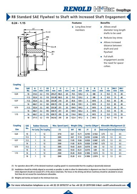
RB St<strong>and</strong>ard SAE Flywheel to Shaft with Increased Shaft Engagement<br />
0.24 - 1.15<br />
A F<br />
C<br />
J<br />
L<br />
L1<br />
D2<br />
S x U<br />
W2<br />
J2<br />
Y G<br />
Q x R<br />
W1<br />
J1<br />
For more information telephone us on +44 (0) 29 20792737 or fax +44 (0) 29 20791360 E-Mail: cardiff.sales@renold.com<br />
67<br />
Features<br />
● Long Boss Inner<br />
members<br />
Benefits<br />
● Allows small<br />
diameter long length<br />
shafts to be used<br />
● Reduces key stress<br />
● Allows increased<br />
distance between<br />
shaft end <strong>and</strong><br />
flywheel<br />
● Full shaft<br />
engagement avoids<br />
the need for spacer<br />
collars<br />
Coupling<br />
Size SAE A C D2 F G J L L1 Q R S U MAX.Y MIN.Y<br />
No. mm mm mm mm mm mm mm mm mm mm mm mm mm mm<br />
0.24 10 314.3 3.2 110 295.27 186.5 20 79.5 129.2 6 M8 8 10.5 75 40<br />
11.5 352.4 3.2 110 333.38 186.5 20 79.5 129.2 6 M8 8 10.5 75 40<br />
0.37 11.5 352.4 3.2 120 333.38 210 20 85.8 139.1 6 M10 8 10.5 85 40<br />
14 466.7 3.2 120 438.15 210 20 85.8 139.1 6 M10 8 13.5 85 40<br />
0.73 11.5 352.4 3.2 145 333.38 251 20 104.9 164.2 6 M10 8 10.5 95 55<br />
14 466.7 3.2 145 438.15 251 20 104.9 164.2 6 M10 8 13.5 95 55<br />
1.15 14 466.7 3.2 170 438.15 295 20 114.4 189.2 6 M12 8 13.5 115 55<br />
18 571.5 3.2 170 542.92 295 28 122.4 197.2 6 M12 6 16.7 115 55<br />
Coupling SAE Rubber Elements Max. Speed (rpm) Weight (3)Kg Inertia (3)Kgm<br />
Size<br />
No.<br />
Per Cavity Per Coupling (1) W1 W2 J1 J2 Radial (mm) Axial (mm) Conical (degree)<br />
2 Allowable Misalignment (2)<br />
0.24 10 1 12 3710 8.67 15.71 0.0193 0.1922 0.75 1.5 0.5<br />
11.5 1 12 3305 8.67 17.10 0.0193 0.2546 0.75 1.5 0.5<br />
0.37 11.5 1 12 3305 11.85 19.96 0.0326 0.3087 0.75 1.5 0.5<br />
14 1 12 2500 11.85 28.76 0.0326 0.7487 0.75 1.5 0.5<br />
0.73 11.5 1 12 3305 19.43 24.01 0.0770 0.40 1.0 1.5 0.5<br />
14 1 12 2500 19.43 35.31 0.0770 0.89 1.0 1.5 0.5<br />
1.15 14 1 12 2500 35.28 39.03 0.1896 1.0274 1.5 1.5 0.5<br />
18 1 12 2040 35.28 61.0 0.1896 2.3974 1.5 1.5 0.5<br />
(1) For operation above 80% of the declared maximum coupling speed it is recommended that the coupling is dynamically balanced.<br />
(2) Installations should be initially aligned as accurately as possible. In order to allow for deterioration in alignment over time it is recommended that<br />
initial alignment should not exceed 25% of the above noted data. The forces on the driving <strong>and</strong> driven machinery should be calculated to ensure<br />
that these do not exceed the manufacturers allowables.<br />
(3) Weights <strong>and</strong> inertias are based on the minimum bore size.