TDAS G5 Docking Station Hardware User's Manual - Diversified ...
TDAS G5 Docking Station Hardware User's Manual - Diversified ...
TDAS G5 Docking Station Hardware User's Manual - Diversified ...

Create successful ePaper yourself
Turn your PDF publications into a flip-book with our unique Google optimized e-Paper software.
<strong>TDAS</strong> <strong>G5</strong> <strong>Docking</strong> <strong>Station</strong> <strong>Hardware</strong> User’s <strong>Manual</strong> December 2004<br />
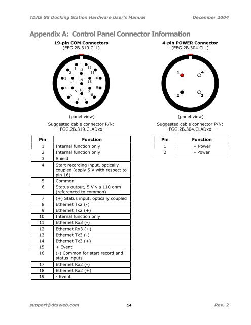
Appendix A: Control Panel Connector Information<br />
19-pin COM Connectors 4-pin POWER Connector<br />
(EEG.2B.319.CLL) (EEG.2B.304.CLL)<br />
Suggested cable connector P/N: Suggested cable connector P/N:<br />
FGG.2B.319.CLADxx FGG.2B.304.CLADxx<br />
Pin Function Pin Function<br />
1 Internal function only 1 + Power<br />
2 Internal function only 2 - Power<br />
3 Shield<br />
4 Start recording input, optically<br />
coupled (apply 5 V with respect to<br />
pin 16)<br />
5 Common<br />
6 Status output, 5 V via 110 ohm<br />
(referenced to common)<br />
7 (+) Status input, optically coupled<br />
8 Ethernet Tx2 (-)<br />
9 Ethernet Tx2 (+)<br />
10 Internal function only<br />
11 Ethernet Rx3 (-)<br />
12 Ethernet Rx3 (+)<br />
13 Ethernet Tx3 (-)<br />
14 Ethernet Tx3 (+)<br />
15 + Event<br />
16 (-) Common for start record and<br />
status inputs<br />
17 Ethernet Rx2 (-)<br />
3<br />
4<br />
18 Ethernet Rx2 (+)<br />
19 - Event<br />
2<br />
14<br />
1<br />
13<br />
19<br />
12<br />
18<br />
11<br />
15 16<br />
17<br />
5<br />
8<br />
6 7<br />
(panel view)<br />
10<br />
9<br />
support@dtsweb.com 14 Rev. 2<br />
1<br />
4<br />
2 3<br />
(panel view)