TDAS G5 Docking Station Hardware User's Manual - Diversified ...
TDAS G5 Docking Station Hardware User's Manual - Diversified ...
TDAS G5 Docking Station Hardware User's Manual - Diversified ...

Create successful ePaper yourself
Turn your PDF publications into a flip-book with our unique Google optimized e-Paper software.
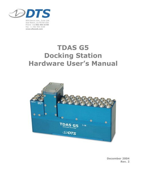
<strong>TDAS</strong> <strong>G5</strong><br />
<strong>Docking</strong> <strong>Station</strong><br />
<strong>Hardware</strong> User’s <strong>Manual</strong><br />
December 2004<br />
Rev. 2
<strong>TDAS</strong> <strong>G5</strong> <strong>Docking</strong> <strong>Station</strong> <strong>Hardware</strong> User’s <strong>Manual</strong> December 2004<br />
Table of Contents<br />
DTS Support.................................................................................................... 3<br />
Introducing the <strong>TDAS</strong> <strong>G5</strong> <strong>Docking</strong> <strong>Station</strong>....................................................... 4<br />
Overview of <strong>TDAS</strong> <strong>G5</strong> <strong>Docking</strong> <strong>Station</strong> Features .............................................. 4<br />
Input Range ................................................................................................. 4<br />
Excitation Sources......................................................................................... 4<br />
Sensor Connectors ........................................................................................ 5<br />
Digital Inputs ............................................................................................... 5<br />
Control Panel................................................................................................ 5<br />
Basic Care and Handling ................................................................................. 6<br />
Shock Rating ................................................................................................ 7<br />
Thermal Considerations ................................................................................. 7<br />
Power Management ........................................................................................ 7<br />
Power Consumption....................................................................................... 8<br />
<strong>TDAS</strong> <strong>G5</strong> <strong>Docking</strong> <strong>Station</strong> Internal Battery ........................................................ 8<br />
Charging the Battery.................................................................................. 8<br />
LED Indicator............................................................................................ 9<br />
Battery Capacity.......................................................................................10<br />
Battery Life Cycle .....................................................................................10<br />
Power-up and Power-down Procedures ............................................................11<br />
Communication Features .............................................................................. 11<br />
Communication Method.................................................................................11<br />
Using Multiple <strong>TDAS</strong> <strong>G5</strong> <strong>Docking</strong> <strong>Station</strong>s.....................................................11<br />
Auxiliary Signals ..........................................................................................12<br />
Start Record Input....................................................................................12<br />
Status Output Signal.................................................................................12<br />
Using the Event Input ................................................................................... 13<br />
Appendix A: Control Panel Connector Information ....................................... 14<br />
Suggested Connector Sources........................................................................15<br />
Appendix B: Mechanical Specifications......................................................... 16<br />
Appendix C: <strong>Hardware</strong> Configuration Specifications..................................... 17<br />
support@dtsweb.com ii Rev. 2
<strong>TDAS</strong> <strong>G5</strong> <strong>Docking</strong> <strong>Station</strong> <strong>Hardware</strong> User’s <strong>Manual</strong> December 2004<br />
DTS Support<br />
<strong>TDAS</strong> systems are designed to be reliable and simple to operate. Should you need<br />
assistance, DTS has support engineers worldwide with extensive product knowledge<br />
and crash test experience to help via telephone, e-mail or on-site visits.<br />
The best way to contact a DTS support engineer is to e-mail support@dtsweb.com.<br />
Your e-mail is immediately forwarded to all DTS support engineers worldwide and is<br />
typically the fastest way to get a response, particularly if you need assistance outside<br />
of normal business hours. For assistance by telephone, please go to<br />
http://www.dtsweb.com/support.html to find the phone number appropriate for your<br />
region of the world.<br />
support@dtsweb.com 3 Rev. 2
<strong>TDAS</strong> <strong>G5</strong> <strong>Docking</strong> <strong>Station</strong> <strong>Hardware</strong> User’s <strong>Manual</strong> December 2004<br />
Introducing the <strong>TDAS</strong> <strong>G5</strong> <strong>Docking</strong> <strong>Station</strong><br />
The <strong>TDAS</strong> <strong>G5</strong> <strong>Docking</strong> <strong>Station</strong> allows for easy installation of a <strong>TDAS</strong> <strong>G5</strong> Data Acquisition<br />
System (DAS) into a rugged enclosure for on-board testing applications. Power,<br />
communication, and event signals are easily accessible via 2B LEMO connectors on the<br />
control panel. Sensors are easily connected via a compact sensor connector panel that<br />
can accommodate a variety of user-specified connectors and pin assignments including<br />
1B LEMO and Tajimi. A <strong>TDAS</strong> <strong>G5</strong> DAS can be moved easily from an in-dummy<br />
application to an on-board docking station for maximum flexibility of data acquisition<br />
resources. <strong>Docking</strong> stations may be interconnected in a chain to create higher<br />
channel-count systems; they may also be interconnected with <strong>TDAS</strong> PRO racks.<br />
This manual discusses the features and options available with the <strong>TDAS</strong> <strong>G5</strong> <strong>Docking</strong><br />
<strong>Station</strong>. To identify the specific hardware included with your system, please see your<br />
packing list.<br />
Overview of <strong>TDAS</strong> <strong>G5</strong> <strong>Docking</strong> <strong>Station</strong> Features<br />
• Built and tested for 100+ G dynamic testing environments.<br />
• 32 fully-programmable sensor input channels.<br />
• Internal battery with a capacity of up to one hour.<br />
• “Smart Charge” circuit helps ensure that the battery receives the proper charge.<br />
• LED indicator for power and battery status.<br />
• Power input is protected against reverse current, over-current, and transient<br />
over-voltage conditions.<br />
• 2 volt and 5 volt excitation sources.<br />
• Ethernet 10/100BaseT/Tx communications allow interconnection with <strong>TDAS</strong> <strong>G5</strong><br />
<strong>Docking</strong> <strong>Station</strong>s or <strong>TDAS</strong> PRO racks.<br />
• Contact-closure event input with 1000-volt isolation.<br />
• Rugged, time constant, momentary power switch prevents inadvertent turn off.<br />
• 16 isolated and protected multi-purpose digital inputs.<br />
• Integral threaded mounting holes.<br />
Please see the DTS web site (www.dtsweb.com) for the latest hardware specifications.<br />
Input Range<br />
The nominal sensor input range is ±2.5 volts (differential) at a gain of 1. The rated<br />
common-mode voltage range is 0.3 to 4.7 volts.<br />
Excitation Sources<br />
<strong>TDAS</strong> <strong>G5</strong> <strong>Docking</strong> <strong>Station</strong>s provide adjustable excitation under software control.<br />
Standard excitation voltages are 2 volt and 5.0 volt. (Other factory options are<br />
available.) Excitation sources for each channel are individually regulated and current<br />
support@dtsweb.com 4 Rev. 2
<strong>TDAS</strong> <strong>G5</strong> <strong>Docking</strong> <strong>Station</strong> <strong>Hardware</strong> User’s <strong>Manual</strong> December 2004<br />
limited (20 mA per channel) to ensure reliable operation even with shorted cables.<br />
Recovery time is
<strong>TDAS</strong> <strong>G5</strong> <strong>Docking</strong> <strong>Station</strong> <strong>Hardware</strong> User’s <strong>Manual</strong> December 2004<br />
Momentary<br />
Power Switch<br />
Basic Care and Handling<br />
<strong>TDAS</strong> <strong>G5</strong> <strong>Docking</strong> <strong>Station</strong> Control Panel<br />
<strong>TDAS</strong> <strong>G5</strong> <strong>Docking</strong> <strong>Station</strong>s are precision devices designed to operate reliably in<br />
dynamic testing environments. Though resistant to many environmental conditions,<br />
care should be taken not to subject the unit to harsh chemicals, submerge it in water,<br />
or drop it onto any hard surface.<br />
WARNING:<br />
Main Power Input<br />
• 13-15 VDC<br />
LED<br />
Indicator<br />
Digital Inputs<br />
• 16 digital inputs<br />
• Event input<br />
Communication Connectors (identical)<br />
• Ethernet 10/100BaseT/Tx<br />
• Status output<br />
• Status input<br />
• Start record input<br />
• Event input<br />
Electronic equipment dropped from desk height onto a solid<br />
floor may experience as much as 10,000 Gs. Under these<br />
conditions, damage to the exterior and/or interior of the unit is<br />
likely.<br />
When transporting the unit, treat it as you might a laptop computer and you should<br />
have no problems. If a <strong>TDAS</strong> <strong>G5</strong> DAS is not installed in the docking station, we<br />
strongly recommend reattaching the clear plastic cap to cover the opening and protect<br />
the connector interface on the docking station. When not in use or if shipping is<br />
required, we suggest that you always place the unit in the padded carrying case<br />
originally provided with your system.<br />
support@dtsweb.com 6 Rev. 2
<strong>TDAS</strong> <strong>G5</strong> <strong>Docking</strong> <strong>Station</strong> <strong>Hardware</strong> User’s <strong>Manual</strong> December 2004<br />
WARNING:<br />
The 216-position, gold-plated, interface connector on the<br />
docking station should be treated with great care. It is<br />
through this interface that all signals enter and exit the DAS.<br />
Any debris, solvents, or oil (even from fingers) can compromise<br />
the integrity of the connections/signals.<br />
If you feel the interface connector on your docking station has become contaminated,<br />
please contact DTS support before attempting any cleaning procedure.<br />
Shock Rating<br />
All <strong>TDAS</strong> <strong>G5</strong> vehicle-/sled-mounted systems are rated for and fully tested to 100+ Gs,<br />
12 msec duration, in all axes. <strong>TDAS</strong> <strong>G5</strong> equipment can be mounted directly on a<br />
vehicle, sled or other dynamic testing device. Mounting methods and mounting bolt<br />
selection should be carefully calculated so as to withstand expected shock loading.<br />
(See Appendix B for the mechanical specifications.)<br />
Thermal Considerations<br />
<strong>TDAS</strong> <strong>G5</strong> systems use extensive power management to minimize heat generation.<br />
Since the system draws the most power when armed, running the calibrations and<br />
arming as late as possible will minimize self-heating.<br />
It is extremely unlikely that excessive heat will ever be an issue in real-world testing<br />
applications using <strong>TDAS</strong> <strong>G5</strong> systems. However, if high ambient temperatures, exposure<br />
to other heat sources, or severely restricted airflow will cause case temperatures<br />
in excess of 50°C (too hot to touch comfortably), the airflow created by a small fan will<br />
increase heat transfer by a factor of 3 to 5. Additionally, always shield the units from<br />
exposure to direct sunlight.<br />
Power Management<br />
A good power source is of paramount importance. Each <strong>TDAS</strong> <strong>G5</strong> <strong>Docking</strong> <strong>Station</strong><br />
should be powered from either:<br />
1) A high-quality 15-volt power supply with a current rating of at least 2 amps (this<br />
would include the <strong>TDAS</strong> PLUS Distributor and <strong>TDAS</strong> PLUS Mini Distributor);<br />
2) A fully-charged 12-volt battery with sufficient capacity for the application.<br />
When installing power supply systems, always consider voltage drops that may occur<br />
due to cables, connectors, power converters, etc. Always remember:<br />
• To ensure the internal battery is fully charged, the minimum input voltage<br />
received by the docking station at its power input connector must be ≥13.8 volts.<br />
• DTS always recommends using an external power source during set-up and<br />
check-out. This will ensure that the internal battery is always fully charged.<br />
support@dtsweb.com 7 Rev. 2
<strong>TDAS</strong> <strong>G5</strong> <strong>Docking</strong> <strong>Station</strong> <strong>Hardware</strong> User’s <strong>Manual</strong> December 2004<br />
Power Consumption<br />
Power off: When connected to sufficient external power, the docking station will draw<br />
up to 600 mA for charging the internal battery.<br />
Power on: When a <strong>TDAS</strong> <strong>G5</strong> system (docking station and DAS) is initially powered, all<br />
sensor excitation sources, signal conditioning electronics, filter circuits and analog-todigital<br />
converters are in a shutdown state. The processor and support circuitry are<br />
always powered. The processor will remain in a reduced power state when not performing<br />
tasks. When the user runs a test set-up, the software automatically energizes<br />
the excitation sources and other circuits. The current draw will increase to as much as<br />
1.4 amps when the system is fully armed and powering 32 full-bridge loads.<br />
During data collection: Once the system has been armed for data collection, all<br />
circuits remain in a full power state until the system finishes storing data. After the<br />
data collection routine is complete, the system de-energizes several circuits to<br />
minimize power consumption. It takes a maximum of 125 seconds after the end of the<br />
data storage window for the system to return to the idle state, which then allows<br />
communication and download.<br />
<strong>TDAS</strong> <strong>G5</strong> <strong>Docking</strong> <strong>Station</strong> Internal Battery<br />
Each <strong>TDAS</strong> <strong>G5</strong> <strong>Docking</strong> <strong>Station</strong> contains a 2.1 AHr, NiMH battery. This battery can<br />
function as the primary power source or as a back-up power source when using<br />
external power. The system ensures a smooth transition from external to internal<br />
power if the external power source is disconnected or shorted during data collection.<br />
Charging the Battery<br />
The two most reliable ways to fully charge the <strong>TDAS</strong> <strong>G5</strong> <strong>Docking</strong> <strong>Station</strong>’s internal<br />
battery are outlined below. (Note that the docking station does not need to be turned<br />
on in order to charge the internal battery. It is also not necessary to install a <strong>TDAS</strong> <strong>G5</strong><br />
DAS unit when charging the docking station.) The ON LED is an indicator of battery<br />
status. (A discussion of the LED indicator begins on page 9.)<br />
1. <strong>Docking</strong> station implemented without an external battery:<br />
Connect a 15-volt power source to the docking station POWER input.<br />
Use this charging set-up for several hours before testing—overnight<br />
works well. (The docking station does not need to be turned on in<br />
order to charge the internal battery. The docking station may be<br />
charged with or without a <strong>TDAS</strong> <strong>G5</strong> DAS installed.)<br />
AC power<br />
15 VDC, 2 A Power Supply<br />
(non-rugged; off-board)<br />
- or –<br />
<strong>TDAS</strong> PLUS Distributor<br />
- or –<br />
<strong>TDAS</strong> PLUS Mini Distributor<br />
<strong>TDAS</strong> <strong>G5</strong><br />
<strong>Docking</strong> <strong>Station</strong><br />
This configuration can also be used during pre-test set-up and<br />
check-out to ensure a full charge.<br />
support@dtsweb.com 8 Rev. 2
<strong>TDAS</strong> <strong>G5</strong> <strong>Docking</strong> <strong>Station</strong> <strong>Hardware</strong> User’s <strong>Manual</strong> December 2004<br />
2. <strong>Docking</strong> station using an external on-board battery:<br />
Connect the docking station to a crashworthy, 12-volt, lead-acid<br />
battery; then connect a high-quality battery charger to the battery.<br />
As the external battery charges above 13 volts, the docking<br />
station’s internal battery will also charge. In this way, all batteries,<br />
including the primary external battery, will charge fully.<br />
AC power Battery Charger<br />
12 V SLA Battery<br />
<strong>TDAS</strong> <strong>G5</strong><br />
(e.g., high quality 5 A unit) (rugged; on-board)<br />
<strong>Docking</strong> <strong>Station</strong><br />
This configuration can also be used during pre-test set-up and<br />
check-out to keep both the external and internal battery continually<br />
charged.<br />
DTS-supplied power supplies and distribution units are designed to meet all criteria for<br />
proper charging and operation. If you need help determining which set-up is best for<br />
your application or if a power supply or charger will meet the power demands, please<br />
contact DTS.<br />
LED Indicator<br />
The <strong>TDAS</strong> <strong>G5</strong> <strong>Docking</strong> <strong>Station</strong> has one LED (red/yellow/green) that provides ongoing<br />
battery status in three ways:<br />
1) Charging when docking station is off (blinking LED);<br />
2) Charging when the docking station is on (solid LED);<br />
3) Discharging when the docking station is on (blinking LED).<br />
When discharging (i.e., drawing power from the internal battery), battery status is<br />
determined dynamically during use. Please pay close attention to the LED as it will<br />
indicate if the battery status is acceptable (green), low (yellow) or at a critical level<br />
(red).<br />
WARNING:<br />
Do not perform any critical tests when the LED indicator is<br />
yellow (battery low) or red (battery critical).<br />
support@dtsweb.com 9 Rev. 2
<strong>TDAS</strong> <strong>G5</strong> <strong>Docking</strong> <strong>Station</strong> <strong>Hardware</strong> User’s <strong>Manual</strong> December 2004<br />
(3 Hz)<br />
Charging when Off<br />
(blinking LED; rate)<br />
(0.4 Hz)<br />
>90%<br />
>20 - 20 -
<strong>TDAS</strong> <strong>G5</strong> <strong>Docking</strong> <strong>Station</strong> <strong>Hardware</strong> User’s <strong>Manual</strong> December 2004<br />
Power-up and Power-down Procedures<br />
The momentary switch located on the control panel is used to turn power on and off.<br />
To turn on a <strong>TDAS</strong> <strong>G5</strong> <strong>Docking</strong> <strong>Station</strong>, press down and hold the switch for 3-<br />
4 seconds until the LED changes status, then release the switch. (The internal powerup<br />
sequence takes ~20 seconds to complete.) (Please see the diagrams on page 10<br />
for information on LED status.)<br />
To turn off a docking station, press down and hold the switch for 3-4 seconds until the<br />
LED changes status, then release the switch. (Please see the diagrams on page 10 for<br />
information on LED status.)<br />
Before restarting a docking station, wait until all <strong>TDAS</strong> <strong>G5</strong> DAS LEDs go completely<br />
dark and then wait 10 seconds more to be sure. An incomplete power-down/power-up<br />
cycle can result in errors, so be certain to follow proper procedures.<br />
Multiple interconnected <strong>TDAS</strong> <strong>G5</strong> <strong>Docking</strong> <strong>Station</strong>s/<strong>TDAS</strong> PRO rack systems should be<br />
powered up at least 10 seconds apart to avoid communication conflicts. (They may be<br />
powered up in any order.) Once power-up of all systems is complete, you can then<br />
start your <strong>TDAS</strong> Control software.<br />
Communication Features<br />
The two 19-pin COM connectors on each <strong>TDAS</strong> <strong>G5</strong> <strong>Docking</strong> <strong>Station</strong> control panel allow<br />
access to all communication features and status lines. These connectors are<br />
functionally identical so you may use either one to connect the communication and<br />
trigger cables provided with your system. (Please see Appendix A for the connector<br />
specifics and pin assignments.)<br />
Communication Method<br />
The <strong>TDAS</strong> <strong>G5</strong> <strong>Docking</strong> <strong>Station</strong> supports the industry-standard Ethernet 10/100BaseT/<br />
Tx communication method. The docking station itself does not contain an IPaddressable<br />
controller; communication is only possible when the docking station<br />
contains a <strong>TDAS</strong> <strong>G5</strong> DAS. Communication is enabled after the power-up sequence has<br />
completed (~20 seconds).<br />
Using Multiple <strong>TDAS</strong> <strong>G5</strong> <strong>Docking</strong> <strong>Station</strong>s<br />
<strong>TDAS</strong> <strong>G5</strong> <strong>Docking</strong> <strong>Station</strong>s can be interconnected in a chain to create higher channelcount<br />
systems. In this way, one docking station can act as the main terminal point for<br />
a multiple docking-station system. <strong>Docking</strong>-station-to-docking-station communications<br />
are accomplished by using a control cable (RDC-xx-xxxx). The procedure for the<br />
making the proper connections is outlined below.<br />
• Using either COM port on the first docking station, connect your PC to the<br />
docking station using the Ethernet communication cable (REC-xx-xxxx) provided<br />
with your system.<br />
support@dtsweb.com 11 Rev. 2
<strong>TDAS</strong> <strong>G5</strong> <strong>Docking</strong> <strong>Station</strong> <strong>Hardware</strong> User’s <strong>Manual</strong> December 2004<br />
• Then, using a control cable (RDC-xx-xxxx), connect the end marked “MASTER”<br />
to the first docking station and the end marked “SLAVE” to either COM port on<br />
the second docking station.<br />
• Using a second control cable, connect the end marked “MASTER” to the open<br />
COM port on the second docking station; connect the end marked “SLAVE” to<br />
either COM port on the third docking station.<br />
• Continue connecting the control cables in this manner so that each docking<br />
station in the middle of the chain has both a “MASTER” and “SLAVE” cable end<br />
connected. The last docking station in the chain will have only the cable end<br />
marked “SLAVE” connected; the other COM port will remain open. (Do not<br />
connect your PC to the last docking station in the chain.) Note: You may use<br />
the open COM port to connect your event input, <strong>TDAS</strong> PLUS Visual Status<br />
Indicator, or other device if desired.<br />
Note that <strong>TDAS</strong> <strong>G5</strong> <strong>Docking</strong> <strong>Station</strong>s may also be interconnected in this manner with<br />
<strong>TDAS</strong> PRO racks.<br />
Auxiliary Signals<br />
Additional auxiliary signals are available on either of the 19-pin COM connectors.<br />
(Please see Appendix A for the connector specifics and pin assignments.) These<br />
signals are:<br />
• Start record input (optically-coupled 0-5 volt signal);<br />
• Status output (0-5 volt, 20 mA output).<br />
Start Record Input<br />
The start record input (used only in recorder mode) is used to send a signal to the<br />
system to begin recording data independent of any event signal. The desired length of<br />
recording time is entered into the <strong>TDAS</strong> Control software. Once the start record signal<br />
is received by the system, data is recorded only for the length of time specified. (An<br />
event signal can be used separately to facilitate post-processing of the data.) Care<br />
should be taken when using this feature so that the desired event is captured within<br />
the data window. (See the <strong>TDAS</strong> Control software manual for additional information.)<br />
Please contact DTS for additional information on how this may be useful in your<br />
application.<br />
Status Output Signal<br />
The status output signal is available for use as an indicator of system status. A typical<br />
application would be in an environment where operators may be a substantial distance<br />
away from the test equipment, in a control room or other remote location, and desire<br />
confirmation from the system that it is armed and healthy prior to testing. The table<br />
below describes this function.<br />
support@dtsweb.com 12 Rev. 2
<strong>TDAS</strong> <strong>G5</strong> <strong>Docking</strong> <strong>Station</strong> <strong>Hardware</strong> User’s <strong>Manual</strong> December 2004<br />
Status Output Functional Description<br />
When the docking station is not armed, the status output is always low (near 0 V),<br />
regardless of signals on the event input.<br />
The status output will be high (near 5 V) ONLY when:<br />
1. The docking station is armed, AND<br />
2. The docking station is ready to record data (is in circular buffer mode, or has<br />
received a start signal in recorder mode), AND<br />
3. The docking station has not received an event signal, AND<br />
4. The docking station’s power status is within acceptable levels.<br />
In circular buffer mode, the status output will go high as you arm the system. It will go<br />
low when the docking station receives an event signal, any A/D circuit stops functioning,<br />
or if the system’s power is outside of acceptable limits.<br />
In recorder mode, the status output will remain low until the system is actually recording<br />
data. The status output will go high when the docking station receives a start record<br />
signal and all other diagnostic checks are within acceptable limits. It will go low when<br />
the docking station receives an event signal, the end of the recording time window is<br />
reached, any A/D circuit stops functioning, or if the system’s power is outside of<br />
acceptable limits.<br />
Using the Event Input<br />
The <strong>TDAS</strong> <strong>G5</strong> <strong>Docking</strong> <strong>Station</strong> contains an isolated, ESD-protected, contact-closure<br />
EVENT input. The EVENT input is available through both of the 19-pin connectors and<br />
the 26-pin connector. (The specific connector pin assignments can be found in<br />
Appendix A.) This input provides a way to use a closure switch in harsh or noisy<br />
environments, without negatively affecting the data acquisition system. A software<br />
trigger can also be used—please see your <strong>TDAS</strong> Control software manual for information<br />
on how to set a software level trigger.<br />
The EVENT input may be used in either of two ways.<br />
• In circular buffer mode, this input actually triggers data collection and is used to<br />
mark zero time (T=0).<br />
• In recorder mode, this input is used to mark T=0 only.<br />
WARNING:<br />
Do not apply external voltages to the event, communication,<br />
status or control output and inputs—this could result in<br />
damage to the unit.<br />
support@dtsweb.com 13 Rev. 2
<strong>TDAS</strong> <strong>G5</strong> <strong>Docking</strong> <strong>Station</strong> <strong>Hardware</strong> User’s <strong>Manual</strong> December 2004<br />
Appendix A: Control Panel Connector Information<br />
19-pin COM Connectors 4-pin POWER Connector<br />
(EEG.2B.319.CLL) (EEG.2B.304.CLL)<br />
Suggested cable connector P/N: Suggested cable connector P/N:<br />
FGG.2B.319.CLADxx FGG.2B.304.CLADxx<br />
Pin Function Pin Function<br />
1 Internal function only 1 + Power<br />
2 Internal function only 2 - Power<br />
3 Shield<br />
4 Start recording input, optically<br />
coupled (apply 5 V with respect to<br />
pin 16)<br />
5 Common<br />
6 Status output, 5 V via 110 ohm<br />
(referenced to common)<br />
7 (+) Status input, optically coupled<br />
8 Ethernet Tx2 (-)<br />
9 Ethernet Tx2 (+)<br />
10 Internal function only<br />
11 Ethernet Rx3 (-)<br />
12 Ethernet Rx3 (+)<br />
13 Ethernet Tx3 (-)<br />
14 Ethernet Tx3 (+)<br />
15 + Event<br />
16 (-) Common for start record and<br />
status inputs<br />
17 Ethernet Rx2 (-)<br />
3<br />
4<br />
18 Ethernet Rx2 (+)<br />
19 - Event<br />
2<br />
14<br />
1<br />
13<br />
19<br />
12<br />
18<br />
11<br />
15 16<br />
17<br />
5<br />
8<br />
6 7<br />
(panel view)<br />
10<br />
9<br />
support@dtsweb.com 14 Rev. 2<br />
1<br />
4<br />
2 3<br />
(panel view)
<strong>TDAS</strong> <strong>G5</strong> <strong>Docking</strong> <strong>Station</strong> <strong>Hardware</strong> User’s <strong>Manual</strong> December 2004<br />
26-pin DIGITAL INPUT Connector<br />
(EEG.2B.326.CLL)<br />
3<br />
1<br />
2<br />
15<br />
16<br />
14<br />
13<br />
23<br />
24<br />
22<br />
12<br />
4 17 25 26<br />
21<br />
11<br />
5 18<br />
19<br />
20 10<br />
6<br />
9<br />
7 8<br />
(panel view)<br />
Suggested cable connector P/N:<br />
FGG.2B.326.CLADxx<br />
Pin Function Pin Function<br />
1 Digital Input 1 14 Common (9 and 10)<br />
2 Common (1 and 2) 15 Digital Input 10<br />
3 Digital Input 2 16 Digital Input 11<br />
4 Digital Input 3 17 Common (11 and 12)<br />
5 Common (3 and 4) 18 Digital Input 12<br />
6 Digital Input 4 19 Digital Input 13<br />
7 Digital Input 5 20 Common (13 and 14)<br />
8 Common (5 and 6) 21 Digital Input 14<br />
9 Digital Input 6 22 Digital Input 15<br />
10 Digital Input 7 23 Common (15 and 16)<br />
11 Common (7 and 8) 24 Digital Input 16<br />
12 Digital Input 8 25 + Event<br />
13 Digital Input 9 26 - Event<br />
Suggested Connector Sources<br />
DTS uses LEMO connectors on the <strong>TDAS</strong> <strong>G5</strong> <strong>Docking</strong> <strong>Station</strong>. If you need to purchase<br />
connectors, we suggest first going to LEMO directly (http://www.lemo.com/index.html).<br />
Their web site and worldwide sales team are very helpful. Should you have difficulty<br />
obtaining a specific part number, they can suggest connector variations or alternates<br />
and explain options that may be useful for your particular application. Another U.S.<br />
source is Alpine Electronics (www.alpine-electronics.com) in San Jose, California. They<br />
are a stocking distributor for LEMO and LEMO-compatible connectors.<br />
support@dtsweb.com 15 Rev. 2
<strong>TDAS</strong> <strong>G5</strong> <strong>Docking</strong> <strong>Station</strong> <strong>Hardware</strong> User’s <strong>Manual</strong> December 2004<br />
Appendix B: Mechanical Specifications<br />
Weight: 2502 grams (LEMO 1B sensor connector panel; <strong>TDAS</strong> <strong>G5</strong> DAS not included)<br />
Torque specification for screws (4) fastening connector<br />
panel: 1.4 to 1.7 Nm or 12 to 15.6 in-lb<br />
5.35 inches/135.89 mm<br />
0.492 inches<br />
12.497 mm<br />
3.961 inches<br />
100.6 mm<br />
0.394 inches<br />
10.008 mm<br />
1.969 inches<br />
50.013 mm<br />
WARNING:<br />
Cover for battery<br />
compartment (typ)<br />
8.76 inches/222.504 mm<br />
9.252 inches/235 mm<br />
Torque specification for screws (4) fastening DAS:<br />
1.6 to 1.8 Nm or 14 to 16 in-lb<br />
M8 x 1.25 pitch screws;<br />
should penetrate docking<br />
station 12 mm<br />
2.362 inches<br />
60 mm<br />
The torque specification is critical for proper connection of the<br />
<strong>TDAS</strong> <strong>G5</strong> DAS (1.6 to 1.8 Nm or 14 to 16 in-lb) and sensor<br />
connector panels (1.4 to 1.7 Nm or 12 to 15.6 in-lb). If the<br />
bolts are tightened too little, good contact will not be made; if<br />
they are tightened too much, damage may result. Please use a<br />
torque wrench if possible.<br />
support@dtsweb.com 16 Rev. 2