IQ plus® 355 - Cisco-Eagle, Inc.
IQ plus® 355 - Cisco-Eagle, Inc.
IQ plus® 355 - Cisco-Eagle, Inc.

You also want an ePaper? Increase the reach of your titles
YUMPU automatically turns print PDFs into web optimized ePapers that Google loves.
2.3.4 Analog Output<br />
If the optional analog output module is installed,<br />
attach the output cable to connector J1 on the analog<br />
output board. Table 2-3 lists the analog output pin<br />
assignments.<br />
Use the ALGOUT menu to configure and calibrate the<br />
analog output module when cabling is complete. See<br />
Section 2.4 for information about installing the analog<br />
output module.<br />
Pin Signal<br />
1 + Current Out<br />
2 – Current Out<br />
3 + Voltage Out<br />
4 – Voltage Out<br />
Table 2-3. Analog Output Module Pin Assignments<br />
2.4 Analog Output Module Installation<br />
To install or replace the analog output module, follow<br />
the steps listed in Section 2.2 on page 4 for opening<br />
the <strong>IQ</strong> plus <strong>355</strong> enclosure.<br />
Mount the analog output module on its standoffs in<br />
the location shown in Figure 2-3 on page 5 and plug<br />
the module input into connector J5 on the <strong>IQ</strong> plus <strong>355</strong><br />
board. Connect output cable to the analog output<br />
module as shown in Table 2-3, then reassemble the<br />
enclosure (Section 2.5).<br />
See Section 7.8 on page 42 for analog output<br />
calibration procedures.<br />
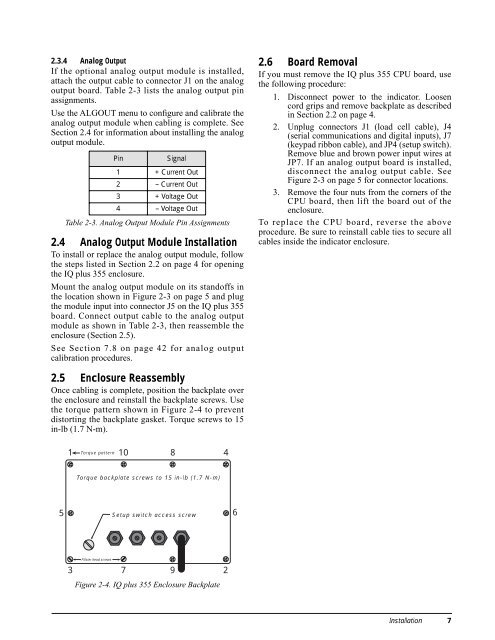
2.5 Enclosure Reassembly<br />
Once cabling is complete, position the backplate over<br />
the enclosure and reinstall the backplate screws. Use<br />
the torque pattern shown in Figure 2-4 to prevent<br />
distorting the backplate gasket. Torque screws to 15<br />
in-lb (1.7 N-m).<br />
1<br />
3<br />
Torque pattern<br />
Fillister head screws<br />
10<br />
Torque backplate screws to 15 in-lb (1.7 N-m)<br />
5 6<br />
Setup switch access screw<br />
7<br />
Figure 2-4. <strong>IQ</strong> plus <strong>355</strong> Enclosure Backplate<br />
8<br />
9<br />
4<br />
2<br />
2.6 Board Removal<br />
If you must remove the <strong>IQ</strong> plus <strong>355</strong> CPU board, use<br />
the following procedure:<br />
1. Disconnect power to the indicator. Loosen<br />
cord grips and remove backplate as described<br />
in Section 2.2 on page 4.<br />
2. Unplug connectors J1 (load cell cable), J4<br />
(serial communications and digital inputs), J7<br />
(keypad ribbon cable), and JP4 (setup switch).<br />
Remove blue and brown power input wires at<br />
JP7. If an analog output board is installed,<br />
disconnect the analog output cable. See<br />
Figure 2-3 on page 5 for connector locations.<br />
3. Remove the four nuts from the corners of the<br />
CPU board, then lift the board out of the<br />
enclosure.<br />
To replace the CPU board, reverse the above<br />
procedure. Be sure to reinstall cable ties to secure all<br />
cables inside the indicator enclosure.<br />
Installation 7