IQ plus® 355 - Cisco-Eagle, Inc.
IQ plus® 355 - Cisco-Eagle, Inc.
IQ plus® 355 - Cisco-Eagle, Inc.

You also want an ePaper? Increase the reach of your titles
YUMPU automatically turns print PDFs into web optimized ePapers that Google loves.
2.3.1 Cable Grounding<br />
Except for the power cord, all cables routed through<br />
the cord grips should be grounded against the<br />
indicator backplate. Do the following to ground<br />
shielded cables:<br />
• Use the lockwashers, clamps, and kep nuts<br />
provided in the parts kit to install grounding<br />
clamps on the backplate studs adjacent to cord<br />
grips. Install grounding clamps only for cord<br />
grips that will be used; do not tighten nuts.<br />
• Route cables through cord grips and grounding<br />
clamps to determine cable lengths required to<br />
reach cable connectors. Mark cables to remove<br />
insulation and shield as described below:<br />
• For cables with foil shielding, strip insulation<br />
and foil from the cable half an inch (15 mm)<br />
past the grounding clamp (see Figure 2-2).<br />
Fold the foil shield back on the cable where<br />
the cable passes through the clamp. Ensure<br />
silver (conductive) side of foil is turned<br />
outward for contact with the grounding<br />
clamp.<br />
• For cables with braided shielding, strip cable<br />
insulation and braided shield from a point just<br />
past the grounding clamp. Strip another half<br />
inch (15 mm) of insulation only to expose the<br />
braid where the cable passes through the<br />
clamp (see Figure 2-2).<br />
To setup switch<br />
JP4<br />
–EXC<br />
+EXC<br />
–SENSE<br />
+SENSE<br />
–SIG<br />
+SIG<br />
6<br />
5<br />
4<br />
3<br />
EEPROM<br />
LOAD CELL CONNECTOR<br />
2<br />
1 J1<br />
JP2<br />
JP1<br />
Microprocessor<br />
X2<br />
U4<br />
LED DRIVER<br />
ON OFF<br />
SET/ISP<br />
A/D Converter<br />
Load cell<br />
compensation jumper<br />
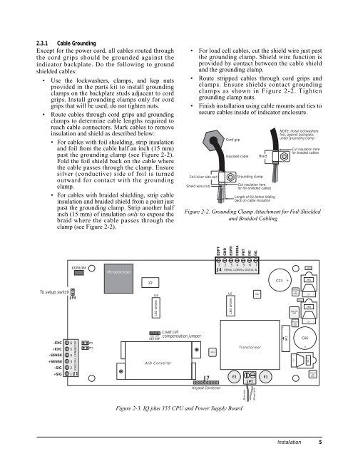
Figure 2-3. <strong>IQ</strong> plus <strong>355</strong> CPU and Power Supply Board<br />
<br />
• For load cell cables, cut the shield wire just past<br />
the grounding clamp. Shield wire function is<br />
provided by contact between the cable shield<br />
and the grounding clamp.<br />
• Route stripped cables through cord grips and<br />
clamps. Ensure shields contact grounding<br />
clamps as shown in Figure 2-2. Tighten<br />
grounding clamp nuts.<br />
• Finish installation using cable mounts and ties to<br />
secure cables inside of indicator enclosure.<br />
NOTE: Install lockwashers<br />
first, against backplate,<br />
Cord grip<br />
under grounding clamp<br />
Cut insulation here<br />
for braided cables<br />
Insulated cable Braid<br />
Foil (silver side out)<br />
Grounding clamp<br />
Length<br />
Shield wire (cut)Cut<br />
insulation here<br />
for foil-shielded cables<br />
of foil before folding<br />
back on cable insulation<br />
Figure 2-2. Grounding Clamp Attachment for Foil-Shielded<br />
and Braided Cabling<br />
+<br />
J7<br />
GND<br />
EDPT<br />
Keypad Connector<br />
GND<br />
EDPR<br />
PRMA<br />
PRT<br />
IN2<br />
IN1<br />
1 2 3 4 5 6 7<br />
J4 SERIAL COMM & DIGITAL IN<br />
U5<br />
LED DRIVER<br />
Transformer<br />
F2 F1<br />
JP7<br />
Blue wire<br />
Brown wire<br />
GND<br />
C23<br />
– +<br />
BR1<br />
+<br />
DIGITAL<br />
+5V<br />
TEST<br />
ANALOG<br />
GND<br />
ANALOG<br />
+5V<br />
TEST<br />
C67<br />
MECCA1<br />
Installation<br />
C66<br />
+<br />
JMP4<br />
VR1<br />
C24<br />
VR2<br />
+<br />
C25 +<br />
VR3<br />
ANALOG<br />
–5V<br />
TEST<br />
5