Motorpact MV Motor Starters Civil Guide IEC - Schneider
Motorpact MV Motor Starters Civil Guide IEC - Schneider
Motorpact MV Motor Starters Civil Guide IEC - Schneider

You also want an ePaper? Increase the reach of your titles
YUMPU automatically turns print PDFs into web optimized ePapers that Google loves.
0<strong>Civil</strong> Engineering<br />
0<strong>Guide</strong><br />
02004<br />
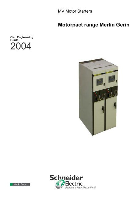
0<strong>MV</strong> <strong>Motor</strong> <strong>Starters</strong><br />
0<strong><strong>Motor</strong>pact</strong> range Merlin Gerin<br />
0<br />
Building a New Electic World<br />
0
<strong>Schneider</strong> Electric 02/2004<br />
0contents<br />
dimensions and weights . . . . . . . . . . . . . . . . . . . . . . . . . . . . . 5<br />
FVNR, RVSS, RVAT, and Incoming Cubicles . . . . . . . . . . . . . 5<br />
FVNR full voltage non-reversing . . . . . . . . . . . . . . . . . . . . . 5<br />
RVSS reduced voltage soft start . . . . . . . . . . . . . . . . . . . . 5<br />
RVAT reduced voltage autotransformer . . . . . . . . . . . . . . . 5<br />
incoming cubicles . . . . . . . . . . . . . . . . . . . . . . . . . . . . . . . . 6<br />
approximate weights . . . . . . . . . . . . . . . . . . . . . . . . . . . . . 6<br />
switchboard with gas discharge tunnel . . . . . . . . . . . . . . . . . 7<br />
space to be provided around switchboard . . . . . . . . . . . . . . . 9<br />
position of <strong>MV</strong> cables . . . . . . . . . . . . . . . . . . . . . . . . . . . . . . . 12<br />
FVNR (375) 6 cables per phase . . . . . . . . . . . . . . . . . . . . 12<br />
FVNR (375) 3 cables per phase . . . . . . . . . . . . . . . . . . . . 12<br />
FVNR (375) dual triplex per phase . . . . . . . . . . . . . . . . . . 12<br />
FVNR (375) single triplex per phase . . . . . . . . . . . . . . . . 12<br />
incoming cubicle (500) 6 cables per phase . . . . . . . . . . . 13<br />
incoming cubicle (500) 3 cables per phase . . . . . . . . . . . 13<br />
incoming cubicle (500) dual triplex per phase . . . . . . . . . 14<br />
incoming cubicle (500) single triplex per phase . . . . . . . . 14<br />
incoming cubicle (750) 6 cables per phase . . . . . . . . . . . 15<br />
incoming cubicle (750) 3 cables per phase . . . . . . . . . . . 15<br />
incoming cubicle (750) dual triplex per phase . . . . . . . . . 16<br />
incoming cubicle (750) single triplex per phase . . . . . . . . 16<br />
floor finishing and cubicle mounting . . . . . . . . . . . . . . . . . . . 17<br />
floor finishing . . . . . . . . . . . . . . . . . . . . . . . . . . . . . . . . . . . . . 17<br />
surface conditioning . . . . . . . . . . . . . . . . . . . . . . . . . . . . . 17<br />
quality of flooring . . . . . . . . . . . . . . . . . . . . . . . . . . . . . . . 17<br />
cubicle mounting . . . . . . . . . . . . . . . . . . . . . . . . . . . . . . . . . . 17<br />
summary of different mounting methods . . . . . . . . . . . . . . . . 17<br />
base layout–mounting . . . . . . . . . . . . . . . . . . . . . . . . . . . . . . 19<br />
FVNR, RVSS, RVAT, and incoming cubicle base layouts–<br />
standard and earthquake . . . . . . . . . . . . . . . . . . . . . . . . . . . . 19<br />
FVNR (375) base layout–standard mounting . . . . . . . . . . 19<br />
FVNR (375) base layout–earthquake mounting . . . . . . . . 20<br />
RVSS (750) base layout–standard mounting . . . . . . . . . . 21<br />
RVAT (1125) base layout–standard mounting . . . . . . . . . 22<br />
RVAT (1125) base layout–earthquake mounting . . . . . . . 23<br />
RVAT (1500) base layout–standard mounting . . . . . . . . . 24<br />
RVAT (1500) base layout–earthquake mounting . . . . . . . 25<br />
incoming cubicle (500) base layout–standard mounting . 26<br />
incoming cubicle (500) base layout–earthquake mounting 27<br />
incoming cubicle (750) base layout–standard mounting . 28<br />
incoming cubicle (750) base layout–earthquake mounting 29<br />
46032-700-07/3
FVNR, RVSS, RVAT, and<br />
Incoming Cubicles<br />
FVNR full voltage<br />
non-reversing<br />
RVSS reduced voltage soft start<br />
RVAT reduced voltage<br />
autotransformer<br />
(All dimensions in mm)<br />
375 946 79<br />
<strong>Schneider</strong> Electric 02/2004<br />
2300<br />
0dimensions and weights<br />
2300<br />
375 750<br />
946<br />
79<br />
375<br />
375<br />
1125<br />
1500<br />
2300<br />
2300<br />
946 79<br />
946 79<br />
46032-700-07/5
incoming cubicles<br />
approximate weights<br />
0<br />
508<br />
500 mm<br />
749<br />
750 mm<br />
2300<br />
946 79<br />
946 79<br />
436032-700-07/6 02/2004<br />
<strong>Schneider</strong> Electric<br />
416<br />
2300<br />
<strong>Motor</strong> Starter Type<br />
554<br />
Enclosure<br />
Width (mm)<br />
Approximate<br />
Weight (kg)<br />
FVNR 375 472<br />
RVSS 750 1094**<br />
RVAT* 1125 1200**<br />
1500 1357**<br />
Incoming cubicle 500 350<br />
750 900<br />
*Autotransformer weight to be added<br />
**Includes FVNR Module
ecommendations<br />
ceiling clearance for<br />
installing an anti-arcing<br />
tunnel or IPX-1<br />
installation above the<br />
switchboard<br />
installation<br />
wall mounting<br />
Note: To use the standard tunnel,<br />
the wall surface must be able to<br />
support brackets.<br />
middle of room mounting<br />
If H > 4 m: installation of tunnel not<br />
necessary for internal arc<br />
withstand. H must be 2.80 m or over<br />
for a standard tunnel to be installed.<br />
All installation of equipment, such<br />
as lamps or light fittings, is<br />
prohibited to avoid stepping on the<br />
switchboard cover plates.<br />
MCSet<br />
beyond<br />
<strong>Schneider</strong> Electric 02/2004<br />
804<br />
MCset (Beyond)<br />
0switchboard with gas<br />
discharge tunnel<br />
992<br />
992<br />
946<br />
946<br />
The connection between the gas<br />
discharge tunnel and the outside<br />
will be studied case by case. As<br />
far as possible, make this<br />
connection at the end of the<br />
switchboard.<br />
2730<br />
2730<br />
46032-700-07/7
436032-700-07/8 02/2004<br />
<strong>Schneider</strong> Electric
civil engineering with<br />
maintenance space<br />
FVNR<br />
A: access to room<br />
B: main earth lead<br />
C: reserved slab space, if<br />
necessary, for routing of LV<br />
cables<br />
D: reserved slab space for routing<br />
of <strong>MV</strong> cables<br />
Incoming cubicle<br />
A: access to room<br />
B: main earth lead<br />
C: reserved slab space for routing<br />
of <strong>MV</strong> cables<br />
Recommendations<br />
(*): minimum dimension (in mm)<br />
The depth of the maintenance<br />
space can be reduced, it must<br />
respect the bending radius of the<br />
cables.<br />
MCset (Beyond)<br />
<strong>Schneider</strong> Electric 02/2004<br />
C<br />
804<br />
425<br />
825<br />
1450<br />
825.00<br />
1658.00<br />
992 1520–1720<br />
946<br />
208<br />
B<br />
D<br />
C<br />
B<br />
0space to be provided<br />
around switchboard<br />
A<br />
The bending radius of the cable<br />
must be compliant with the<br />
minimum bending requirements of<br />
the cable manufacturer.<br />
A<br />
2500<br />
1200<br />
2800<br />
2500<br />
1100<br />
2800<br />
46032-700-07/9
civil engineering with<br />
duct space<br />
FVNR<br />
A: access to room<br />
B: main earth lead<br />
C: reserved slab space, if<br />
necessary, for routing of LV<br />
cables<br />
D: reserved slab space for routing<br />
of <strong>MV</strong> cables<br />
Recommendations<br />
(*): minimum dimension (in mm) The depth of the maintenance<br />
space can be reduced, it must<br />
respect the bending radius of the<br />
cables<br />
MCset (Beyond)<br />
804<br />
425<br />
825<br />
1450<br />
436032-700-07/10 02/2004<br />
<strong>Schneider</strong> Electric<br />
992<br />
946<br />
208<br />
B<br />
D<br />
C<br />
A<br />
2500<br />
1200<br />
2800<br />
0
space to be provided around<br />
a switchboard<br />
(*): minimum dimension (in mm)<br />
The L dimension is a function of the functional<br />
widths of the switchboard<br />
A. this dimension must be equal to:<br />
545 mm* for operation (extraction and<br />
positioning of moving parts<br />
1745 mm* for the extraction of one<br />
functional unit without displacing the<br />
other. (1925 mm* for functional units with<br />
a depth of 1725 mm)<br />
B. this dimension must be equal to:<br />
800 mm* for the 900 mm wide functional<br />
unit at the end of the switchboard<br />
500 mm* for all other functional units<br />
C. this dimension must be equal to:<br />
200 mm* for a 1500 mm deep functional<br />
unit with internal arcing withstand on<br />
three sides<br />
50 mm* for a 1700 mm deep cubicle with<br />
internal arcing withstand on three sides<br />
D. access to the room<br />
E. side end sheets<br />
<strong>Schneider</strong> Electric 02/2004<br />
0<br />
C<br />
E<br />
E<br />
235<br />
main earth lead<br />
16 x 51<br />
FVNR<br />
RVAT<br />
FVNR<br />
Transition<br />
Main<br />
incoming<br />
circuit<br />
breaker<br />
Couping<br />
circuit<br />
breaker<br />
Main<br />
incoming<br />
circuit<br />
breaker<br />
Transition<br />
FVNR<br />
FVNR<br />
RVAT<br />
main earth lead<br />
16 x 51<br />
A<br />
500*<br />
L<br />
B<br />
37<br />
37<br />
D<br />
46032-700-07/11
FVNR (375) 6 cables per phase<br />
maximum external cable<br />
Single–conductor 70 mm<br />
FVNR (375) 3 cables per phase<br />
maximum external cable<br />
Single–conductor 70 mm<br />
FVNR (375) dual triplex<br />
per phase<br />
maximum external cable<br />
Three–conductor 90 mm<br />
FVNR (375) single triplex<br />
per phase<br />
maximum external cable<br />
Three–conductor 90 mm<br />
0position of <strong>MV</strong> cables<br />
187<br />
187<br />
132<br />
132<br />
84 Typ<br />
84 Typ<br />
110<br />
436032-700-07/12 02/2004<br />
<strong>Schneider</strong> Electric<br />
946<br />
946<br />
946<br />
861<br />
783<br />
822<br />
822<br />
946<br />
822<br />
375<br />
375<br />
375<br />
375
incoming cubicle (500) 6 cables<br />
per phase<br />
maximum external cable<br />
Single–conductor 70 mm<br />
incoming cubicle (500) 3 cables<br />
per phase<br />
maximum external cable<br />
Single–conductor 70 mm<br />
<strong>Schneider</strong> Electric 02/2004<br />
225<br />
225<br />
84 Typ<br />
84 Typ<br />
946<br />
946<br />
781<br />
703<br />
703<br />
556<br />
478<br />
478<br />
331<br />
253<br />
253<br />
508<br />
508<br />
46032-700-07/13
incoming cubicle (500) dual<br />
triplex per phase<br />
maximum external cable<br />
Three–conductor 90 mm<br />
incoming cubicle (500) single<br />
triplex per phase<br />
maximum external cable<br />
Three–conductor 90 mm<br />
175<br />
175<br />
100<br />
436032-700-07/14 02/2004<br />
<strong>Schneider</strong> Electric<br />
946<br />
742<br />
742<br />
517<br />
517<br />
292<br />
292<br />
508<br />
508
incoming cubicle (750) 6 cables<br />
per phase<br />
maximum external cable<br />
Single–conductor 70 mm<br />
incoming cubicle (750) 3 cables<br />
per phase<br />
maximum external cable<br />
Single–conductor 70 mm<br />
<strong>Schneider</strong> Electric 02/2004<br />
375<br />
375<br />
84 Typ<br />
84 Typ<br />
946<br />
946<br />
781<br />
703<br />
703<br />
556<br />
478<br />
478<br />
331<br />
253<br />
253<br />
750<br />
750<br />
46032-700-07/15
incoming cubicle (750)<br />
dual triplex per phase<br />
maximum external cable<br />
Three–conductor 90 mm<br />
incoming cubicle (750) single<br />
triplex per phase<br />
maximum external cable<br />
Three–conductor 90 mm<br />
325<br />
325<br />
100<br />
436032-700-07/16 02/2004<br />
<strong>Schneider</strong> Electric<br />
946<br />
946<br />
742<br />
742<br />
517<br />
517<br />
292<br />
292<br />
750<br />
750
floor finishing<br />
surface conditioning<br />
quality of flooring<br />
cubicle mounting<br />
summary of different<br />
mounting methods<br />
A: front rail, supply on switchboard<br />
installation<br />
B: <strong>MV</strong> functional unit FVNR cable opening<br />
C: LV cable opening<br />
D: horizontal adjustment with the rear<br />
actuators<br />
E: rear rail<br />
F: rear rail, supply on switchboard<br />
installation<br />
The floor’s surface evenness<br />
must allow for a 2 metre rule to be<br />
placed on it in any direction and<br />
on all sides so that there are no<br />
deflections greater than 5 mm.<br />
To roll extraction tool for moving<br />
parts (ERT, OESD, etc.) without<br />
damaging the floor, it must meet<br />
the following criteria:<br />
For standard or earthquake–<br />
resistant civil engineering,<br />
see installation manual<br />
46032-700-08.<br />
<strong>Schneider</strong> Electric 02/2004<br />
D<br />
E<br />
F<br />
0floor finishing and cubicle<br />
mounting<br />
B<br />
B<br />
compressive strength<br />
33 MPa<br />
For civil engineering<br />
structure built with a false floor<br />
or beams, consult our technical<br />
department.<br />
standard civil engineering<br />
C<br />
A<br />
earthquake–resistant civil<br />
engineering<br />
C<br />
A<br />
46032-700-07/17
436032-700-07/18 02/2004<br />
<strong>Schneider</strong> Electric
FVNR, RVSS, RVAT, and<br />
incoming cubicle base<br />
layouts–standard and<br />
earthquake<br />
FVNR (375) base layout–<br />
standard mounting<br />
reserved space over all civil engineering<br />
A: front rail<br />
B: rear rail (earthquake mounting only)<br />
C: <strong>MV</strong> cable opening<br />
D: LV cable opening<br />
E: rear supporting plate<br />
F: positioning of front anchors<br />
G: positioning of rear anchors<br />
H. positioning of rear actuator<br />
D<br />
19<br />
51<br />
178<br />
F (22 h x 36 w)<br />
LV cable opening detail<br />
65<br />
288<br />
<strong>Schneider</strong> Electric 02/2004<br />
F<br />
A<br />
H<br />
E<br />
C<br />
A<br />
86<br />
95<br />
C<br />
0base layout–mounting<br />
940<br />
203<br />
190<br />
375<br />
935<br />
see LV<br />
cable<br />
opening<br />
detail at<br />
left<br />
D<br />
510<br />
310<br />
G<br />
D<br />
F<br />
65<br />
70<br />
102<br />
42<br />
46032-700-07/19
FVNR (375) base layout–<br />
earthquake mounting<br />
reserved space over all civil engineering<br />
A: front rail<br />
B: rear rail<br />
C: <strong>MV</strong> cable opening<br />
D: LV cable opening<br />
E: rear supporting plate<br />
F: positioning of front anchors<br />
G: positioning of rear anchors<br />
D<br />
19<br />
51<br />
178<br />
F (22 h x 36 w)<br />
LV cable opening detail<br />
65<br />
288<br />
F<br />
A<br />
G<br />
B<br />
B<br />
C<br />
A<br />
436032-700-07/20 02/2004<br />
<strong>Schneider</strong> Electric<br />
86<br />
95<br />
940<br />
203<br />
190<br />
375<br />
C D<br />
935<br />
See LV<br />
cable<br />
opening<br />
detail at<br />
left.<br />
510<br />
310<br />
G<br />
D<br />
F<br />
65<br />
70<br />
102<br />
42
RVSS (750) base layout–<br />
standard mounting<br />
reserved space over all civil engineering<br />
A: front rail<br />
B: rear rail (earthquake mounting only)<br />
C: <strong>MV</strong> cable opening<br />
D: LV cable opening<br />
E: rear supporting plate<br />
F: positioning of front anchors<br />
G: positioning of rear anchors<br />
H: positioning of rear actuator<br />
D<br />
19<br />
51<br />
178<br />
F (22 h x 36 w)<br />
LV cable opening detail<br />
65<br />
288<br />
<strong>Schneider</strong> Electric 02/2004<br />
A<br />
H<br />
E<br />
F<br />
A<br />
86<br />
95<br />
C<br />
940<br />
578<br />
559<br />
749<br />
935<br />
D<br />
510<br />
310<br />
see LV<br />
cable<br />
opening<br />
detail at<br />
left<br />
G<br />
D<br />
F<br />
65<br />
70<br />
102<br />
42<br />
46032-700-07/21
RVAT (1125) base layout–<br />
standard mounting<br />
reserved space over all civil engineering<br />
A: front rail<br />
B: rear rail (earthquake mounting only)<br />
C: <strong>MV</strong> cable opening<br />
D: LV cable opening<br />
E: rear supporting plate<br />
F: positioning of front anchors<br />
G: positioning of rear anchors<br />
H: positioning of rear actuator<br />
I: transformer rails (2 places)<br />
J: positioning of transformer anchors<br />
C<br />
D<br />
A<br />
86<br />
95<br />
F<br />
A<br />
G<br />
H<br />
E<br />
436032-700-07/22 02/2004<br />
<strong>Schneider</strong> Electric<br />
952<br />
206 737<br />
308 533<br />
940<br />
933<br />
1124<br />
559<br />
131<br />
65<br />
70<br />
G<br />
F<br />
J<br />
I<br />
42
RVAT (1125) base layout–<br />
earthquake mounting<br />
reserved space over all civil engineering<br />
A: front rail<br />
B: rear rail<br />
C: <strong>MV</strong> cable opening<br />
D: LV cable opening<br />
E: rear supporting plate<br />
F: positioning of front anchors<br />
G: positioning of rear anchors<br />
H: transformer rails (2 places)<br />
I: positioning of transformer anchors<br />
<strong>Schneider</strong> Electric 02/2004<br />
B<br />
C<br />
D<br />
A<br />
86<br />
206<br />
95<br />
F<br />
A<br />
G<br />
B<br />
933<br />
1124<br />
940<br />
952<br />
737<br />
308 533<br />
559<br />
131<br />
65<br />
70<br />
G<br />
F<br />
46032-700-07/23<br />
I<br />
H<br />
42
RVAT (1500) base layout–<br />
standard mounting<br />
reserved space over all civil engineering<br />
A: front rail<br />
B: rear rail (earthquake mounting only)<br />
C: <strong>MV</strong> cable opening<br />
D: LV cable opening<br />
E: rear supporting plate<br />
F: positioning of front anchors<br />
G: positioning of rear anchors<br />
H: positioning of rear actuator<br />
I: transformer rails (2 places)<br />
J: positioning of transformer anchors<br />
C<br />
D<br />
A<br />
86<br />
95<br />
F<br />
A<br />
G<br />
H<br />
E<br />
436032-700-07/24 02/2004<br />
<strong>Schneider</strong> Electric<br />
381<br />
1327<br />
736<br />
483 533<br />
1308<br />
1499<br />
940<br />
559<br />
154<br />
65<br />
70<br />
42<br />
G<br />
F<br />
J<br />
I
RVAT (1500) base layout–<br />
earthquake mounting<br />
reserved space over all civil engineering<br />
A: front rail<br />
B: rear rail<br />
C: <strong>MV</strong> cable opening<br />
D: LV cable opening<br />
E: rear supporting plate<br />
F: positioning of front anchors<br />
G: positioning of rear anchors<br />
H: transformer rails (2 places)<br />
I: positioning of transformer anchors<br />
<strong>Schneider</strong> Electric 02/2004<br />
B<br />
C<br />
D<br />
A<br />
86<br />
95<br />
F<br />
A<br />
G<br />
B<br />
38<br />
1327<br />
1308<br />
1499<br />
940<br />
736<br />
483 533<br />
559<br />
154<br />
65<br />
70<br />
42<br />
G<br />
F<br />
46032-700-07/25<br />
I<br />
H
incoming cubicle (500) base<br />
layout–standard mounting<br />
reserved space over all civil engineering<br />
A: front rail<br />
B: rear rail (earthquake mounting only)<br />
C: <strong>MV</strong> cable opening<br />
D: LV cable opening<br />
E: rear supporting plate<br />
F: positioning of front anchors<br />
G: positioning of rear anchors<br />
H: positioning of rear actuator<br />
D<br />
19<br />
51<br />
178<br />
F (22 h x 36 w)<br />
LV cable opening detail<br />
65<br />
288<br />
F<br />
G<br />
H<br />
E<br />
A<br />
436032-700-07/26 02/2004<br />
<strong>Schneider</strong> Electric<br />
759<br />
86<br />
95<br />
660<br />
279<br />
940<br />
C/D<br />
336<br />
318<br />
508<br />
935<br />
D<br />
See LV<br />
cable<br />
opening<br />
detail at<br />
left.<br />
G<br />
C<br />
F<br />
65<br />
42<br />
70<br />
102
incoming cubicle (500) base<br />
layout–earthquake mounting<br />
reserved space over all civil engineering<br />
A: front rail<br />
B: rear rail<br />
C: <strong>MV</strong> cable opening<br />
D: LV cable opening<br />
E: rear supporting plate<br />
F: positioning of front anchors<br />
G: positioning of rear anchors<br />
D<br />
19<br />
51<br />
178<br />
F (22 h x 36 w)<br />
LV cable opening detail<br />
65<br />
288<br />
<strong>Schneider</strong> Electric 02/2004<br />
G<br />
B<br />
F<br />
A<br />
B<br />
A<br />
759<br />
86<br />
95<br />
660<br />
279<br />
336<br />
318<br />
508<br />
940<br />
C/D<br />
935<br />
See LV<br />
cable<br />
opening<br />
detail at<br />
left.<br />
G<br />
C<br />
D<br />
F<br />
42<br />
65<br />
70<br />
102<br />
46032-700-07/27
incoming cubicle (750) base<br />
layout–standard mounting<br />
reserved space over all civil engineering<br />
A: front rail<br />
B: rear rail (earthquake mounting only)<br />
C: <strong>MV</strong> cable opening<br />
D: LV cable opening<br />
E: rear supporting plate<br />
F: positioning of front anchors<br />
G: positioning of rear anchors<br />
H: positioning of rear actuator<br />
D<br />
19<br />
51<br />
178<br />
F (22 h x 36 w)<br />
LV cable opening detail<br />
65<br />
288<br />
G<br />
A<br />
G<br />
H<br />
E<br />
A<br />
759<br />
436032-700-07/28 02/2004<br />
<strong>Schneider</strong> Electric<br />
86<br />
246<br />
95<br />
660<br />
940<br />
C/D<br />
578<br />
279<br />
559<br />
749<br />
935<br />
See LV<br />
cable<br />
opening<br />
detail at<br />
left.<br />
G<br />
C<br />
D<br />
F<br />
65<br />
70<br />
102<br />
42
incoming cubicle (750) base<br />
layout–earthquake mounting<br />
reserved space over all civil engineering<br />
A: front rail<br />
B: rear rail<br />
C: <strong>MV</strong> cable opening<br />
D: LV cable opening<br />
E: rear supporting plate<br />
F: positioning of front anchors<br />
G: positioning of rear anchors<br />
D<br />
19<br />
51<br />
178<br />
F (22 h x 36 w)<br />
LV cable opening detail<br />
65<br />
288<br />
<strong>Schneider</strong> Electric 02/2004<br />
F<br />
A<br />
G<br />
B<br />
B<br />
A<br />
759<br />
86<br />
95<br />
578<br />
246 279<br />
660<br />
559<br />
749<br />
940<br />
C/D<br />
935<br />
Ssee LV<br />
cable<br />
opening<br />
detail at<br />
left.<br />
G<br />
C<br />
D<br />
F<br />
65<br />
70<br />
102<br />
46032-700-07/29
other methods of<br />
installation<br />
RVSS (750) base layout–<br />
alternate mounting<br />
946<br />
998<br />
946<br />
59<br />
881 856<br />
Designates mounting locations.<br />
Use (4) 12 mm mounting bolts<br />
with DIN9021B washers.<br />
110<br />
86<br />
60<br />
92<br />
18<br />
Bottom cable installation with<br />
conduit.<br />
Top cable entry installation:<br />
0base layout–other installation<br />
methods<br />
— Direct on line (FVNR)<br />
— Reduced Voltage<br />
Autotransformer (RVAT)<br />
— Reduced Voltage Soft Start<br />
(RVSS)<br />
— Incoming Line Section<br />
749<br />
Top View<br />
749<br />
Floor Plan<br />
Preparing the site<br />
Ensure that the floor is level within 2<br />
mm per 305 mm, or a maximum of 6<br />
mm within the area of the controller<br />
line-up.<br />
436032-700-07/30 02/2004<br />
<strong>Schneider</strong> Electric<br />
254<br />
51<br />
19<br />
92<br />
70<br />
Control conduit area<br />
657<br />
161<br />
Alternate rear mounting location.<br />
Use (2) 10mm mounting bolts.<br />
835<br />
Control Conduit Area
incoming cubicle (500)<br />
base layout–alternate<br />
mounting<br />
Power cable<br />
conduit area<br />
998 946<br />
59<br />
946 88 856<br />
Designates mounting locations.<br />
Use (4) 12 mm mounting bolts<br />
with DIN9021B washers<br />
110<br />
86<br />
60<br />
92<br />
18<br />
TOP VIEW<br />
365<br />
436032-700-07/31 02/2004<br />
<strong>Schneider</strong> Electric<br />
508<br />
508<br />
254<br />
FLOOR PLAN<br />
51<br />
19<br />
70<br />
Control conduit area<br />
161<br />
Alternate rear mounting location.<br />
Use (2) 10mm mounting bolts.<br />
99<br />
657 759 835<br />
Control conduit area
incoming cubicle (750)<br />
base layout–alternate<br />
mounting<br />
998<br />
946<br />
Power cable<br />
conduit area<br />
59<br />
881 856<br />
946<br />
478<br />
110<br />
70<br />
235<br />
86<br />
60<br />
Designates<br />
mounting locations.<br />
Use (4)12 mm<br />
mounting bolts<br />
with DIN9021B<br />
washers.<br />
122<br />
92<br />
18<br />
Power cable conduit area<br />
(See suggested conduit arrangements)<br />
749<br />
TOP VIEW<br />
749<br />
FLOOR PLAN<br />
254<br />
Control<br />
conduit<br />
area<br />
161<br />
51<br />
Alternate rear mounting location.<br />
Use (2) 10mm mounting bolts.<br />
657<br />
19<br />
92<br />
70<br />
436032-700-07/32 02/2004<br />
<strong>Schneider</strong> Electric<br />
99<br />
759<br />
835<br />
Control<br />
conduit area<br />
Top entry suggested<br />
conduit arrangements<br />
2<br />
A. (2) 400 mm per phase<br />
2<br />
(3) 240 mm per phase<br />
2<br />
(5) 185 mm per phase<br />
2<br />
(6) 120 mm per phase<br />
2<br />
B. (2) 400 mm per phase<br />
2<br />
(3) 240 mm perphase<br />
2<br />
(4) 185 mm per phase<br />
2<br />
(4) 120 mm per phase<br />
127.0 127.0<br />
2<br />
C. (4) 750 mm per phase<br />
2<br />
(4) 400 mm perphase<br />
2<br />
(6) 240 mm per phase<br />
2<br />
(6) 120 mm per phase<br />
152.4<br />
152.4<br />
2<br />
D. (6) 400 mm per phase<br />
NOTES:<br />
1. For top entry, if cable is fed from cable tray, all cable sizes may be in a 254 mm NON-VENTED pullbox 3000 A (arc resistant), will<br />
require a 432 mm pullbox.<br />
2. Due to the minimum required cable bending space, when cable is fed from conduit, a 432 mm pullbox is required for all cables above<br />
120 mm . A 254 mm pullbox may be used for 120 mm cables with out current transformers.<br />
2 2<br />
3. Current transformers may be used with conduit plans "A" & "B" or cables fed from cable trays only.<br />
(1) 150 mm<br />
EMT conduit area<br />
(2) 100 mm<br />
EMT conduit area<br />
76.2<br />
76.2<br />
(2) 150 mm<br />
EMT conduit area<br />
(6) 100 mm<br />
EMT conduit area<br />
76.2<br />
76.2
RVAT (1125) base layout–<br />
alternate mounting<br />
946<br />
881<br />
998 946<br />
59<br />
856<br />
Designates mounting locations.<br />
Use (4) 12 mm mounting bolts<br />
with DIN9021B washers<br />
110<br />
86<br />
60<br />
92<br />
18<br />
TOP VIEW<br />
FLOOR PLAN<br />
436032-700-07/33 02/2004<br />
<strong>Schneider</strong> Electric<br />
1124<br />
1124<br />
254<br />
51<br />
92<br />
Control conduit area<br />
161<br />
Alternate rear mounting location.<br />
Use (2) 10mm mounting bolts.
RVAT (1500) base layout–<br />
alternate mounting<br />
946<br />
998 946<br />
881<br />
59<br />
856<br />
Designates mounting locations.<br />
Use (4) 12 mm mounting bolts<br />
with DIN9021B washers<br />
110<br />
86<br />
60<br />
92<br />
18<br />
TOP VIEW<br />
FLOOR PLAN<br />
436032-700-07/34 02/2004<br />
<strong>Schneider</strong> Electric<br />
1499<br />
1499<br />
254<br />
51<br />
92<br />
Control<br />
conduit<br />
area<br />
161<br />
Alternate rear<br />
mounting location.<br />
Use (2) 10mm<br />
mounting bolts.
RVSS(750) base layout–<br />
alternate mounting<br />
946<br />
998<br />
946<br />
59<br />
881 856<br />
Designates mounting locations.<br />
Use (4) 12 mm mounting bolts<br />
with DIN9021B washers<br />
110<br />
86<br />
60<br />
95<br />
18<br />
436032-700-07/35 02/2004<br />
<strong>Schneider</strong> Electric<br />
749<br />
TOP VIEW<br />
749<br />
FLOOR PLAN<br />
254<br />
51<br />
19<br />
70<br />
92<br />
Control conduit area<br />
657<br />
161<br />
Designates mounting locations.<br />
Use (4) 12 mm mounting bolts<br />
with DIN9021B washers<br />
835<br />
Control conduit area
<strong>Schneider</strong> Electric Industries SAS<br />
Address:<br />
330 Weakley Road<br />
Smyrna, TN 37167, USA<br />
1888-778-2377<br />
http:/www.schneiderelectric.com<br />
The <strong>Schneider</strong> group service centres are at your service for:<br />
engineering and technical assistance<br />
commissioning<br />
training<br />
preventive and corrective maintenance<br />
adaptation<br />
spare parts.<br />
Contact your sales representative who will put you in touch with your nearest<br />
<strong>Schneider</strong> group service centre or call us on 33 (0)4 76 57 60 60<br />
(Grenoble, France).<br />
The content of this bulletin is subject to change without notice. As standards, specifications and<br />
designs change from time to time, please ask for confirmation of the information given in this<br />
publication.<br />
This document has been printed<br />
on ecological paper.<br />
Design: <strong>Schneider</strong> Electric Technical Publications Department, Nashville, TN, USA<br />
46032-700-07 02/2004<br />
<strong><strong>Motor</strong>pact</strong> © 2004 - <strong>Schneider</strong> Electric - All rights reserved.