appendix a: practica experiment ems-1: am modulation / demodulation
appendix a: practica experiment ems-1: am modulation / demodulation
appendix a: practica experiment ems-1: am modulation / demodulation

You also want an ePaper? Increase the reach of your titles
YUMPU automatically turns print PDFs into web optimized ePapers that Google loves.
Modulation Syst<strong>ems</strong> EMS310 1<br />
_______________________________________________________________________________________________________<br />
APPENDIX A: PRACTICA<br />
EXPERIMENT EMS-1: AM MODULATION / DEMODULATION<br />
OBJECTIVES: To theoretically analyse AM <strong>modulation</strong> and de<strong>modulation</strong> in the time and frequency domains and<br />
investigate a chopper modulator/demodulator implementation thereof.<br />
I PREREQUISITES<br />
Knowledge of elementary Fourier theory (time-frequency relationships and Fourier-identities), <strong>am</strong>plitude <strong>modulation</strong> (AM),<br />
convolution/correlation and filter analysis and synthesis is required.<br />
This work must be done in your lab book that is especially kept for this purpose. Note that it must be your own work, and in<br />
your own handwriting (i.e. your personal observations, conclusions, etc.)! No copies of probl<strong>ems</strong> and theoretical work, with<br />
the exceptions of sketches that has been taken from books and sources for references purposes, may be pasted into your lab<br />
books!!!<br />
II REFERENCES<br />
[1] B.P. Lathi and Z. Ding, Modern Digital and Analog Communication Syst<strong>ems</strong>, 4 th Edition, Oxford University<br />
Press, 2010. ISBN: 978-0-19-538493-2<br />
[2] B. P. Lathi, Modern Digital and Analog Communication Syst<strong>ems</strong>,3 rd Edition, Oxford University Press, 1998.<br />
ISBN: 0-19-511009-9<br />
[3] John G. Proakis and Masoud Salehi, Communication Syst<strong>ems</strong> Engineering, 2 nd Edition, Prentice-Hall, 2002,<br />
Chapter 3. ISBN: 0-13-061793-8<br />
[4] S. Haykin, Communication Syst<strong>ems</strong>, 3rd edition, Wiley, 1994, Chapter 3 pp 121-151. ISBN: 0-471-57176-8<br />
III THEORETICAL PREPARATION AND PRELIMINARY REPORT<br />
P.1) Consult and study the references above. Identify three distinct methods whereby information can be transmitted by<br />
employing a cosinusoidal ‘carrier’ signal as information bearer.<br />
P.2) Is a modulator a linear time-invariant (LTI) system? Illustrate/motivate your answer.<br />
P.3) Investigate the multiplication operation in the following cases:<br />
P.3.1) multiply two decimal numbers, say 3330 x 1110. Establish whether there is any resemblance with convolution.<br />
Explain/Motivate your answer.<br />
P.3.2) Now multiply the numbers 33 x 11, using their binary representation with 8-bit word lengths. Identify the use of any<br />
specific algorithm, if any, in doing this. Is there any relation to convolution? How does the algorithm cope with negative<br />
numbers?<br />
P.3.3) Propose a linear analogue device (give complete specifications) capable of multiplying any two analogue values<br />
(voltages) in the range ±1 V and specify it’s circuit diagr<strong>am</strong>. What happens if the <strong>am</strong>plitude range of the multiplier terms<br />
is increased to ±5 V?<br />
P.3.4) Propose a binary device that can perform the multiplication in 3.2, and provide full circuit details.<br />
P.4) Identify at least two commercial applications of AM and specify the version of AM <strong>modulation</strong> used in each case. Give<br />
as many <strong>modulation</strong> par<strong>am</strong>eters/specifications possible for each application (e.g, IF frequency used, typical <strong>modulation</strong><br />
bandwidths, <strong>modulation</strong> indices etc).<br />
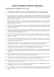
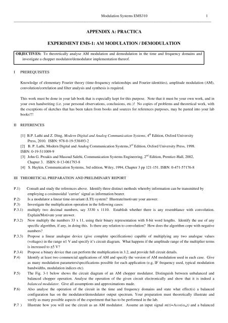
P.5) The Fig. 3-1 below shows the circuit diagr<strong>am</strong> of an AM chopper modulator. Distinguish between unbalanced and<br />
balanced chopper operation. Analyse the operation of the given circuit electronically and show that it is indeed a<br />
balanced modulator. Give all assumptions and approximations made.<br />
P.6) Also analyse the operation of the circuit in the time and frequency domains and state what effect(s) a balanced<br />
configuration has on the modulator/demodulator output spectrum. Your preparation must theoretically illustrate and<br />
verify as many possible aspects of the <strong>experiment</strong> that has to be performed in the lab.<br />
P.7 ) Illustrate how you will use the circuit as an AM modulator. Assume an input signal m(t)=Acos(ωmt) and a balanced
Modulation Syst<strong>ems</strong> EMS310 2<br />
_______________________________________________________________________________________________________<br />
external switching signal Ps(t) with <strong>am</strong>plitude ±B=±5Volt and frequency fc=1/Tc >> fm Hz] to drive the electronic switch.<br />
What is the effective (internal) carrier signal Peff (t) equal to in this case, so that y(t)= Peff (t).m(t) ?<br />
Fig. 3-1 Chopper modulator block diagr<strong>am</strong>.<br />
HINT: Carry out separate analyses for the <strong>am</strong>plifier with the switch in the closed and open states, respectively.<br />
P.6.3) Specify the output filter for both unbalanced and balanced operation, so that an undistorted AM output signal will be<br />
obtained in both cases.<br />
P.6.4) What effect does this filter have on the final output time signal v(t), compared to the signal y(t)? Illustrate with sketches<br />
in the frequency and time domains<br />
P.6.5) How would you modify the circuit to yield an unbalanced chopper modulator?<br />
V EQUIPMENT NEEDED<br />
Two signal generators (one for the information signal, the other for the carrier), oscilloscope, spectrum analyser, power supplies,<br />
volt meters, etc. Furthermore, it is expected from each student to build his own <strong>experiment</strong>al modules, if necessary, when<br />
such building blocks are not provided as part of the laboratory equipment.<br />
VI EXPERIMENTAL PREPARATION<br />
E.1) Build and test the chopper modulator beforehand, and verify correct operation by inspecting the output waveform with<br />
elementary <strong>modulation</strong> signals as input. Also duplicate the chopper modulator in Figure 1, for the purpose of using it as a<br />
synchronous AM demodulator.<br />
E.2) Devise a method whereby the effective switching signal, Peff(t), of the chopper modulator in Figure 1 can be determined and<br />
measured. Use this signal to derive an expression for the chopper modulator output, v(t)=m(t).Peff(t).<br />
E.3) All subsequent <strong>experiment</strong>al measurements should be taken in both the time and frequency domains simultaneously.<br />
VII EXPERIMENT ASSIGNMENTS<br />
AM Modulation<br />
M.1) Investigate AM <strong>modulation</strong> of the chopper modulator. Observe both time and frequency domain waveforms and<br />
corresponding spectra and compare with theory.<br />
M.2) Investigate what effect a DC-offset of the modulating signal, m(t), has on the AM output signal. What is this version of<br />
AM <strong>modulation</strong> called and when/where is it used?<br />
M.3 ) Compare y(t) and v(t) (see Figure 1) and explain any differences (time- and frequency-wise).
Modulation Syst<strong>ems</strong> EMS310 3<br />
_______________________________________________________________________________________________________<br />
AM de<strong>modulation</strong><br />
D.1) Implement a simple low pass filter or band pass filter to use at the output of the AM modulator in Figure 1. Specify the<br />
required bandwidth in each case.<br />
D.2) Add the necessary subsyst<strong>ems</strong> to the AM modulator in VII 1 above in order to demodulate the AM signal, v(t). How<br />
would you recover the original modulating signal, m(t), from the output of the AM chopper demodulator:<br />
D.2.1) In the case of AM suppressed carrier <strong>modulation</strong>?;<br />
D.2.2) In the case of AM with carrier <strong>modulation</strong>?<br />
Identify all unwanted demodulator terms in each case and describe how you would eliminate them.<br />
D.3) Investigate the effect of AM de<strong>modulation</strong> with an unsynchronised (out-of-phase) carrier at the AM receiver.<br />
VIII LABORATORY RESULTS<br />
1. Even though this <strong>experiment</strong> requires group work, each student must be able to demonstrate each <strong>experiment</strong>al assignment in<br />
VII, document his/her own observations and results in his/her lab book and compare it with theory.<br />
2. Each student in the group must be able to answer questions individually.<br />
IX EVALUATION TEST<br />
A short optical mark reader evaluation test will be taken in class on the date and time to be determined.<br />
REMARKS:<br />
The given AM chopper modulator will be used again in subsequent <strong>experiment</strong>s, which will investigate various forms of<br />
synchronisation and carrier recovery in AM and digital <strong>modulation</strong> syst<strong>ems</strong>. It is therefore important to take particular care<br />
with the construction of the chopper modulator and to keep it intact for future lab sessions.
Modulation Syst<strong>ems</strong> EMS310 4<br />
_______________________________________________________________________________________________________<br />
OBJECTIVES<br />
EXPERIMENT EMS-2: FM MODULATION / DEMODULATION<br />
To theoretically analyse FM-<strong>modulation</strong> in the time and frequency domains and investigate several<br />
modulator/demodulator implementation methods<br />
I PREREQUISITES<br />
Knowledge of elementary Fourier theory (time-frequency relationships and Fourier-identities), frequency <strong>modulation</strong> (FM), basic<br />
electronic design principles and filter analysis and synthesis is required.<br />
This work must be done in your lab book, which is especially kept for this purpose. Note that it must be your own work, and in<br />
your own handwriting (i.e. your personal observations, conclusions, etc.)! No copies of probl<strong>ems</strong> and theoretical work, with<br />
the exceptions of sketches that has been taken from books and sources for references purposes, may be pasted into your lab<br />
books!!!<br />
II REFERENCES<br />
[1] B.P. Lathi and Z. Ding, Modern Digital and Analog Communication Syst<strong>ems</strong>, 4 th Edition, Oxford University<br />
Press, 2010. ISBN: 978-0-19-538493-2<br />
[2] B. P. Lathi, Modern Digital and Analog Communication Syst<strong>ems</strong>,3 rd Edition, Oxford University Press, 1998.<br />
ISBN: 0-19-511009-9<br />
[3] John G. Proakis and Masoud Salehi, Communication Syst<strong>ems</strong> Engineering, 2 nd Edition, Prentice-Hall, 2002,<br />
Chapter 3. ISBN: 0-13-061793-8<br />
III THEORETICAL PREPARATION<br />
NOTE: Your preparation/analysis must theoretically illustrate and verify as many possible aspects of the <strong>experiment</strong> that has to<br />
be performed in the lab as possible.<br />
P.1) Do probl<strong>ems</strong> 5.2-1 and 5.2-6 from [1] (Lathi), and 5.32 and 5.36 from [3] (Proakis).<br />
P.2) Is an FM-modulator a linear time-invariant (LTI) system? Illustrate/motivate your answer.<br />
P.3) Identify at least two applications of FM. Give as many <strong>modulation</strong> par<strong>am</strong>eters/specifications possible for each<br />
application (e.g, IF frequency used, typical <strong>modulation</strong> bandwidths, frequency deviation, <strong>modulation</strong> indices etc).<br />
P.4) Analyse the operation of a narrowband and wideband FM/PM modulator in the time and frequency domains. Draw<br />
phasor diagr<strong>am</strong>s and illustrate the principle of angle <strong>modulation</strong>, as opposed to <strong>am</strong>plitude <strong>modulation</strong>. Quantify the errors<br />
made in the narrowband/wideband angle <strong>modulation</strong> processes, e.g., residual <strong>am</strong>plitude <strong>modulation</strong>, phase error etc.<br />
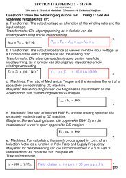
P.5) The following figure shows the circuit diagr<strong>am</strong> of a par<strong>am</strong>etric FM-generator using a ‘varicap’.<br />
P.5.1) Analyse the operation of the circuit and show that it indeed produces an FM signal. Show that the expression for the<br />
oscillating frequency is given by:<br />
where Cvo denotes the varicap capacitance at nominal reverse bias Vo and Ce=C1.C2/(C1+C2). The instantaneous output frequency,<br />
as a function of the input control signal, m(t), is:<br />
⎡ ∆ C ⎤<br />
v<br />
fi ≈ fo<br />
. ⎢1−<br />
⎥<br />
⎣⎢<br />
2(<br />
Cv + C o e)<br />
⎦⎥<br />
f<br />
o<br />
⎡ 1 ⎤<br />
= ⎢<br />
⎥<br />
⎣⎢<br />
2π L0( Cv + C o e)<br />
⎦⎥
Modulation Syst<strong>ems</strong> EMS310 5<br />
_______________________________________________________________________________________________________<br />
Where ∆Cv=Cv-CVo= Kc.m(t), and Kc [F/Volt] is the varicap capacitance-to-voltage conversion factor.<br />
P.5.2) Investigate the possibilities of generating narrowband as well as wideband FM-signals with the given circuit. Which are<br />
the limiting factors and can they be overcome? Assume an input signal m(t)=Mcos(ωmt).<br />
CLAPP Voltage Controlled Oscillator (VCO)<br />
P.6) Design an FM-discriminator using a suitable approximation to a differentiator (such as, e.g., the one illustrated in the<br />
accompanying design ex<strong>am</strong>ple).<br />
P.7) Design a simple envelope detector (similar to the one used for AM-detection).<br />
IV EQUIPMENT<br />
Two signal generators (one for the information signal, one for the carrier), oscilloscope, spectrum analyser, power supplies, volt<br />
meters, etc. Furthermore, it is expected from each student to build his own <strong>experiment</strong>al modules, if necessary, when such<br />
building blocks are not provided as part of the laboratory equipment.<br />
V EXPERIMENTAL PREPARATION<br />
E.1) Determine the voltage-to-frequency transfer function of the carrier frequency generator corresponding to your lab work<br />
bench (identify the generator by making a note of its number in your lab book!) Calculate the VCO-constant, kf [Hz/V], from<br />
the measured input-output graph, when the carrier frequency is fc=10 kHz.<br />
E.2) Determine/specify the FM-<strong>modulation</strong> par<strong>am</strong>eters to <strong>experiment</strong>ally reproduce the spectrum of the FM-signal calculated<br />
in [3] problem 3.32 (but with fc=10 kHz in stead of 1 MHz), using the FM-generator (VCO) measured/quantified in 1) above.<br />
Take as modulating signal, m(t)=Mcos(ωmt), with M=2 Volt and fm=1 kHz.<br />
E.3) All subsequent <strong>experiment</strong>al measurements should be taken in both the time and frequency domains simultaneously.<br />
VI EXPERIMENTAL ASSIGNMENTS<br />
FM-<strong>modulation</strong><br />
M.1) Verify the value of the FM-<strong>modulation</strong> constant in V, E.1) by applying the first-Bessel-zero test.<br />
M.2 Illustrate NBFM.<br />
M.3) Reproduce the spectrum of the WBFM-signal of Problem 3.32 in [3]. Compare your result with theory.<br />
M.4) Illustrate Woodward’s theorem i , by reducing fm to several Hz, and appropriately adjusting the <strong>am</strong>plitude of m(t).<br />
M.5) Investigate the phenomenon known as β-multiplication at a carrier frequency of f3=3.fc, by generating the appropriate<br />
harmonic of the signal in M.3) above.
Modulation Syst<strong>ems</strong> EMS310 6<br />
_______________________________________________________________________________________________________<br />
FM-de<strong>modulation</strong><br />
D.1) Illustrate FM-de<strong>modulation</strong> by applying your FM-generator output to the FM-discriminator and envelope detector<br />
designed for this purpose.<br />
VII LABORATORY RESULTS<br />
1. Each student must demonstrate each <strong>experiment</strong>al assignment in VI, document his/her own observations and results in his/her<br />
lab book and compare it with theory.<br />
2. Each student in the group must be able to answer question individually.<br />
VIII EVALUATION TEST<br />
A short optical marksheet test will be taken in class on completion of this <strong>experiment</strong>.<br />
REMARKS:<br />
Although the best part of the FM-modulator <strong>experiment</strong> can be conducted by using standard lab equipment, bonus marks will be<br />
in order when students demonstrate their own FM-generator design.<br />
______________________<br />
1 Woodward’s theorem states that the spectrum (or power density spectrum) of an Ultra Wideband FM-signal, v WBFM (t), aproaches and has the s<strong>am</strong>e form as the<br />
Amplitude Density Function (a-wdf) of the information signal, m(t).
Modulation Syst<strong>ems</strong> EMS310 7<br />
_______________________________________________________________________________________________________<br />
OBJECTIVES<br />
Theoretically analyse the PLL<br />
Design and implement a PLL for carrier tracking.<br />
Design and implement a PLL for FM de<strong>modulation</strong>.<br />
EXPERIMENT EMS-3: PLL-APPLICATIONS<br />
I INTRODUCTION, PREPARATION AND PREREQUISITES<br />
A knowledge of <strong>am</strong>plitude- (AM) and angle <strong>modulation</strong> (FM and PM), convolution/correlation, elementary Fourier-theory<br />
(time/frequency-relationships and Fourier-identities) and elementary control theory (feedback) is required. .<br />
It is recommended that sections III to V ( theoretical preparation and system analysis ) be done prior to the scheduled open lab<br />
sessions. Answer all questions in your lab book, which is kept especially for this purpose. Note that it must be your own<br />
work, and in your own handwriting (i.e. your personal observations, conclusions, etc.)! No copies of probl<strong>ems</strong> and theoretical<br />
work, with the exceptions of sketches that has been taken from books and sources for references purposes, may be pasted into<br />
your lab books!!!<br />
In advance: Study the specifications and operation of a specific Voltage-Controlled-Oscillator (VCO) signal generator in the<br />
laboratory (make a note of the equipment number for later use). This was also done in <strong>practica</strong>l 2.<br />
II REFERENCES<br />
[1] B.P. Lathi and Z. Ding, Modern Digital and Analog Communication Syst<strong>ems</strong>, 4 th Edition, Oxford University<br />
Press, 2010. ISBN: 978-0-19-538493-2<br />
[2] B. P. Lathi, Modern Digital and Analog Communication Syst<strong>ems</strong>,3 rd Edition, Oxford University Press, 1998.<br />
ISBN: 0-19-511009-9<br />
[3] John G. Proakis and Masoud Salehi, Communication Syst<strong>ems</strong> Engineering, 2 nd Edition, Prentice-Hall, 2002,<br />
Chapter 3. ISBN: 0-13-061793-8<br />
III THEORITICAL PREPARATION<br />
1) Consult and study the references above. Identify at least three applications of a PLL.<br />
2) Study and describe the fund<strong>am</strong>entals of the operation of a PLL, identify the main elements and ascertain yourself of the<br />
function and purpose of each par<strong>am</strong>eter, subsystem and component. Your preparation must theoretically illustrate and verify<br />
as many possible aspects of the <strong>experiment</strong> that has to be performed in the lab.<br />
3) Describe, with the aid of the necessary expressions and sketches, the concepts hold-in range and pull-in range (capture<br />
range) of a PLL. How does the noise effective bandwidth, natural frequency and d<strong>am</strong>pening factor of the PLL influence these<br />
ranges?<br />
4) Ex<strong>am</strong>ine theoretically how the input signal <strong>am</strong>plitude, Ac [volt], influences the operation of the PLL.<br />
5) Sketch the block diagr<strong>am</strong> of a system which will recover a carrier from a DSB-AM-SC signal. Analyse in detail.<br />
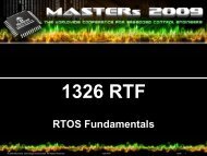
6) The following figure shows the circuit diagr<strong>am</strong> of a balanced chopper modulator. v t)<br />
= Acos(<br />
t )<br />
ω + φ<br />
1(<br />
1 1<br />
6.1) Analyse the operation of the circuit and show that it is indeed a balanced modulator (refer to Exp 1).<br />
6.2) Illustrate how you will use the circuit as a phase detector. Assume an input signal and a balanced switching signal p(t) with<br />
<strong>am</strong>plitude B=5Volt and frequency fc=1/Tc [Hz].
Modulation Syst<strong>ems</strong> EMS310 8<br />
_______________________________________________________________________________________________________<br />
HINTS:<br />
Show that the chopper modulator, followed by a LPF, fulfils the function of a correlator, i.e. that it gives a voltage output that is<br />
directly proportional to the relative time shift between the two correlator inputs.<br />
Note that a time shift can be written as a phase difference, which is exactly the function the phase detector fulfills.<br />
Balanced-Chopper Modulator<br />
P.7) Sketch a block diagr<strong>am</strong> of a PLL-based FM demodulator. Analyse it in detail.<br />
P.8) Illustrate how you will use an XOR-gate as a phase detector. Plot the VCO control signal vs. the phase error. Determine the<br />
gain of the XOR phase detector.<br />
IV EQUIPMENT NEEDED<br />
Two signal generators (one with VCO-output), Oscilloscope, spectrum analyser, power supplies, volt meters, etc. Furthermore, it<br />
is expected from each student to build his own <strong>experiment</strong>al modules, if necessary, when such building blocks are not<br />
provided as part of the laboratory equipment. To this purpose students are encouraged to purchase their own set of basic lab<br />
equipment 2 .<br />
V EXPERIMENTAL PREPARATION<br />
E.1) In advance, study the specification and operation of a specific Voltage-Controlled-Oscillator (VCO) signal generator in the<br />
laboratory (make a note of the equipment number for later use).<br />
E.2) Measure and plot the voltage-to-frequency transfer curve of the VCO by plotting the instantaneous frequency, fi(t) [Hz],<br />
against the input (control) voltage vi [Volt], around the nominal PLL-frequency of say fc=10 [kHz], where the latter is<br />
typically the carrier frequency. Calculate, from this, the VCO-constant, kf [Hz/Volt] as well as the VCO-transfer constant, kω<br />
[rad/v-sec]. The latter is an important PLL-design par<strong>am</strong>eter.<br />
E.3) Use the chopper modulator in Figure 1 as phase detector. Determine the effective phase detector constant, KD [V/rad].<br />
E.4) Design and implement a second-order PLL that will be able to lock onto a signal within the VCO frequencyrange of 8 to 11<br />
kHz, without frequency or phase error (refer [3]). Additional PLL-design details is attached. Determine your total PLL-loop<br />
gain? Specify units!<br />
E.5) Design and implement a second-order PLL that will be able to demodulated an FM signal. Choose a carrier frequency in the<br />
order of fc=10 kHz and a sinusoidal message with a frequency of fm=1 kHz.<br />
2 Sharp nosed pliers, cutters, soldering iron, screw driver, basic electronic components, isolated electric wire, set of oscilloscope probes<br />
e tc
Modulation Syst<strong>ems</strong> EMS310 9<br />
_______________________________________________________________________________________________________<br />
VI EXPERIMENT ASSIGNMENTS<br />
CARRIER RECOVERY<br />
A.1) Choose an arbitrary sinusoidal signal within the PLL frequency range as carrier and demonstrate the PLL’s ability to lock<br />
onto and track this carrier.<br />
A.2) Determine the phase detector transfer function as a function of the phase difference and compare it with theory.<br />
A.3) Measure the pull-in- and hold-in (lock) ranges of the PLL, respectively, and compare it with the theoretical predicted<br />
results.<br />
A.4) Determine what effect the input signal <strong>am</strong>plitude, Ac [Volt], has on the locking behaviour of the PLL.<br />
A.5) Throughout this <strong>experiment</strong> plot time and frequency domain measurements at important points in your PLL circuit.<br />
DEMODULATION OF AN FM SIGNAL<br />
F.1) Use a PLL to recover the message m(t) from an FM modulated signal.<br />
F.2) Determine what effect the message bandwidth has on the de<strong>modulation</strong> performance of the PLL.<br />
F.3) Throughout this <strong>experiment</strong> plot time and frequency domain measurements at important points in your PLL circuit.<br />
VII LABORATORY RESULTS<br />
1. Each student must document his/her own observations and results in his/her lab book and compare it with theory.<br />
2. Demonstrate each <strong>experiment</strong>al assignment in VI.<br />
3. Each student in the group must be able to answer question individually.