Chapter 10 Symmetrical Faults
Chapter 10 Symmetrical Faults
Chapter 10 Symmetrical Faults

You also want an ePaper? Increase the reach of your titles
YUMPU automatically turns print PDFs into web optimized ePapers that Google loves.
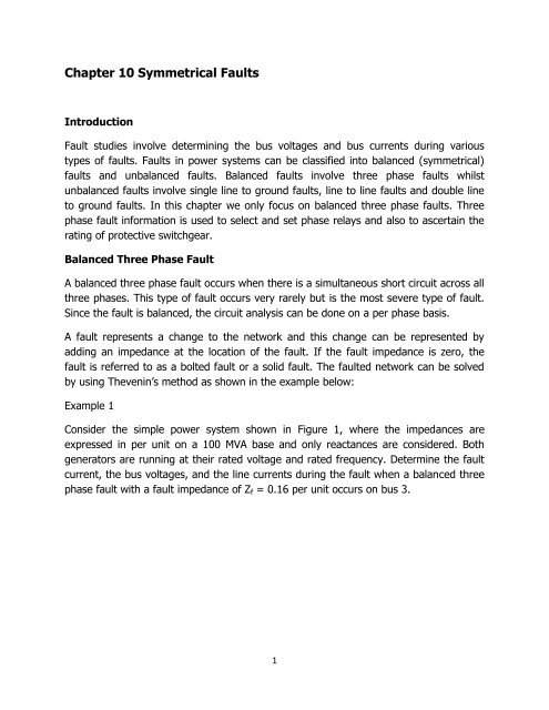
<strong>Chapter</strong> <strong>10</strong> <strong>Symmetrical</strong> <strong>Faults</strong><br />
Introduction<br />
Fault studies involve determining the bus voltages and bus currents during various<br />
types of faults. <strong>Faults</strong> in power systems can be classified into balanced (symmetrical)<br />
faults and unbalanced faults. Balanced faults involve three phase faults whilst<br />
unbalanced faults involve single line to ground faults, line to line faults and double line<br />
to ground faults. In this chapter we only focus on balanced three phase faults. Three<br />
phase fault information is used to select and set phase relays and also to ascertain the<br />
rating of protective switchgear.<br />
Balanced Three Phase Fault<br />
A balanced three phase fault occurs when there is a simultaneous short circuit across all<br />
three phases. This type of fault occurs very rarely but is the most severe type of fault.<br />
Since the fault is balanced, the circuit analysis can be done on a per phase basis.<br />
A fault represents a change to the network and this change can be represented by<br />
adding an impedance at the location of the fault. If the fault impedance is zero, the<br />
fault is referred to as a bolted fault or a solid fault. The faulted network can be solved<br />
by using Thevenin’s method as shown in the example below:<br />
Example 1<br />
Consider the simple power system shown in Figure 1, where the impedances are<br />
expressed in per unit on a <strong>10</strong>0 MVA base and only reactances are considered. Both<br />
generators are running at their rated voltage and rated frequency. Determine the fault<br />
current, the bus voltages, and the line currents during the fault when a balanced three<br />
phase fault with a fault impedance of Z f = 0.16 per unit occurs on bus 3.<br />
1
G1<br />
X G1 =J0.2<br />
X 12 =J0.8<br />
G2<br />
X G2 = J0.4<br />
Bus 1<br />
Bus 2<br />
X 13 = J0.4<br />
X 23 = J0.4<br />
Bus 3<br />
Figure 1<br />
Solution<br />
The fault is simulated by switching on an impedance Z f at bus 3 as shown in the figure<br />
below:<br />
G1<br />
X G1 =J0.2<br />
X 12 =J0.8<br />
G2<br />
X G2 = J0.4<br />
Bus 1<br />
Bus 2<br />
X 13 = J0.4<br />
X 23 = J0.4<br />
Bus 3<br />
Z f =J0.16<br />
By Thevenin’s theorem, the changes in the network voltage due to the fault impedance<br />
Z f can be represented by a voltage source V th with all other voltage sources short<br />
circuited as shown below:<br />
2
Bus 1<br />
X 12 =J0.8<br />
X G1 =J0.2 X G2 = J0.4<br />
Bus 2<br />
X 13 = J0.4<br />
X 23 = J0.4<br />
Bus 3<br />
V th<br />
Z f =J0.16<br />
From the above figure, the fault current at bus 3 is<br />
I 3 (F) =<br />
V th is the Thevenin voltage or the pre-fault voltage V 3 (0).<br />
Z 33 is the Thevenin impedance viewed from the faulted bus 3.<br />
Z f is the fault impedance.<br />
Since the generators are running at their rated values, all pre-fault bus voltages are<br />
equal to 1.0 pu i.e V th = V 3 (0) = 1.0 pu<br />
To find the Thevenin impedance, we note that the impedances between buses 1, 2 and<br />
3 form a delta network. We transform this delta network to a star network with the<br />
following equivalent impedances:<br />
Z 1s = Z 2s =<br />
= j0.2 pu<br />
Z 3s =<br />
= j0.1 pu<br />
The star connected network is shown below:<br />
3
Bus 1<br />
X G1 =J0.2 X G2 = J0.4<br />
Bus 2<br />
Z 1s =J0.2<br />
S<br />
Z 3s =J0.1<br />
Z 2s =J0.2<br />
Bus 3<br />
V th<br />
Z f =J0.16<br />
Figure 2:<br />
We also observe from the above figure that the branch from star point S to bus 1 to<br />
ground and the branch from star point S to bus 2 to ground form a parallel network.<br />
The equivalent impedance of the parallel network is<br />
Z eq = = = j0.24 pu<br />
Combining the parallel branches results in the following network as shown below:<br />
Z eq = J0.24<br />
Z 3s =J0.1<br />
Bus 3<br />
V th<br />
Z f =J0.16<br />
The Thevenin impedance as viewed from the faulted bus 3 is<br />
4
Z 33 = Z eq + Z 3s = j0.34 pu<br />
From the above figure the fault current is<br />
I 3 (F) =<br />
=<br />
= -j2 pu<br />
Note that I 3 (F) denotes the current resulting from the fault at bus 3.<br />
(b) Before we calculate the bus voltages during the fault, we first calculate the voltage<br />
changes at each of the buses during the fault. Considering Figure 2, the fault current is<br />
split between the two parallel branches containing bus 1 and bus 2 as follows:<br />
I Bus1 =<br />
I Bus2 =<br />
I 3 (F) = -j1.2 pu<br />
I 3 (F) = -j0.8 pu<br />
Voltage changes at the three buses due to the fault are then calculated as follows:<br />
At bus 1: The direction of fault current opposes to the generator current, so there will<br />
be a decrease in the voltage which is indicated with a minus below<br />
V 1 = -I bus1 X G1 = -(-j1.2)(j0.2) = -0.24 pu<br />
At bus 2: The direction of fault current opposes to the generator current, so there will<br />
be a decrease in the voltage which is indicated with a minus below<br />
V 2 = -I bus2 X G2 = -(-j0.8)(j0.4) = -0.32 pu<br />
At bus 3: The change in voltage is the sum of V th and the volt drop across Z f due to<br />
I 3 (f), therefore<br />
V 3 = -V th + I 3 (F)Z f = -1 + (-j2)(j0.16) = -0.68 pu<br />
The bus voltages during the fault are calculated as follows:<br />
V 1 (F) = V 1 (0) + V 1<br />
= 1 – 0.24<br />
= 0.76 pu<br />
5
Note that V 1 (F) denotes the voltage at bus 1 during the fault and<br />
V 1 (0) denotes the voltage at bus 1 before the fault i.e. the pre-fault voltage. Similarly<br />
V 2 (F) = V 2 (0) + V 2<br />
= 1 – 0.32<br />
= 0.68 pu<br />
V 3 (F) = V 3 (0) + V 3<br />
= 1 – 0.68<br />
= 0.32 pu<br />
(c) The line currents are calculated as follows:<br />
For the line between bus 1 and bus 2<br />
I 12 (F) =<br />
=<br />
I 13 (F) =<br />
= -j0.1 pu<br />
=<br />
I 23 (F) =<br />
= -j1.1 pu<br />
=<br />
= -j0.9 pu<br />
<strong>Symmetrical</strong> Fault Analysis using the Bus Impedance Matrix<br />
Solving the faulted network using Thevenin’s method involves reducing the network and<br />
is not efficient and applicable to large networks. A more efficient method involves using<br />
6
nodal analysis where the elements of the bus impedance matrix are used to calculate<br />
the fault currents and bus voltages during the fault.<br />
In chapter 7 the injected bus currents in terms of bus voltages for a n-bus network was<br />
calculated as<br />
I bus = Y bus V bus (1)<br />
I bus is the bus current vector entering the bus and Y bus is the bus admittance matrix.<br />
The diagonal element of the i th bus is the sum of the admittances connected to the i th<br />
bus:<br />
Y ii =<br />
with j i<br />
The off diagonal element is equal to the negative of the admittance between bus i and<br />
the other buses connected to it:<br />
Y ij = Y ji = -y ij where y ij is the admittance between bus i and bus j.<br />
For a fault at bus k, the current entering every bus except the faulted bus k is zero thus<br />
equation 1 becomes<br />
<br />
=<br />
Equation (2) can be written as<br />
<br />
<br />
(2)<br />
I bus (F) = Y bus V bus (3)<br />
Solving for the bus voltage changes in equation (3) gives<br />
V bus = Y bus -1 I bus (F)<br />
= Z bus I bus (F) (4)<br />
Z bus = Y bus -1 is the bus impedance matrix<br />
The bus voltages during the fault are obtained by adding (superposition) the pre-fault<br />
bus voltages and the bus voltage changes during the fault, as shown below<br />
V bus (F) = V bus (0) + V bus (5)<br />
Substituting (4) into equation (5) gives<br />
7
V bus (F) = V bus (0) + Z bus I bus (F) (6)<br />
Equation (6) can be written in matrix form as<br />
= + (7)<br />
Equation (7) can be written as a system of n equations as follows:<br />
V 1 (F) = V 1 (0) – Z 1K I k (F)<br />
V 2 (F) = V 2 (0) – Z 2K I k (F)<br />
......................<br />
V k (F) = V k (0) – Z kK I k (F)<br />
(7A)<br />
......................<br />
V n (F) = V n (0) – Z nK I k (F)<br />
The voltage at bus k during the fault is V k (F) which is the k th equation in the set of n<br />
equation (indicated in italics). So<br />
V k (F) = V k (0) – Z kK I k (F) (8)<br />
But the voltage at bus k during the fault is the product of fault impedance Z f and fault<br />
current I k (F) i.e. V k (F) = Z f I k (F), therefore equation (8) becomes<br />
Z f I k (F) = V k (0) – Z kK I k (F)<br />
Solving for I k (F) gives<br />
I k (F) = (9)<br />
Thus the fault current I k (F) for a fault at bus k depends on the pre-fault voltage V k (0) at<br />
bus k, the diagonal element Z kk of the bus impedance matrix Z bus and the fault<br />
impedance Z f . Remember that for a bolted fault or a solid fault Z f = 0.<br />
From equation (7A), for any bus i the bus voltage during the fault is<br />
8
V i (F) = V i (0) - Z ik I k (F)<br />
(9a)<br />
Substituting equation (9) into the above equation gives<br />
V i (F) = V i (0) - Z ik (<strong>10</strong>)<br />
If the bus voltages during the fault are known, the current in all lines during the fault<br />
can be calculated as follows: For the line joining bus i and bus j with line impedance z ij<br />
the short circuit (fault) current is this line is<br />
I ij (F) = (11)<br />
Note that if the bus impedance matrix is known the fault current and bus voltages<br />
during the fault are easily obtained from equations 9 and <strong>10</strong>. This method is more<br />
practical and all fault calculations are done using this method. One way to find Z bus is to<br />
first find the the bus admittance matrix Y bus and then find its inverse using some maths<br />
package like MATLAB.<br />
Example 2<br />
In this example, example 1 above is now repeated using the bus impedance method.<br />
Consider the simple power system shown in Figure 3, where the impedances are<br />
expressed in per unit on a <strong>10</strong>0 MVA base and only reactances are considered. Both<br />
generators are running at their rated voltage and rated frequency. Using the bus<br />
impedance method, determine the fault current, the bus voltages, and the line currents<br />
during the fault when a balanced three phase fault with a fault impedance of Z f = 0.16<br />
per unit occurs on bus 3.<br />
G1<br />
X G1 =J0.2<br />
X 12 =J0.8<br />
G2<br />
X G2 = J0.4<br />
Bus 1<br />
Bus 2<br />
X 13 = J0.4<br />
X 23 = J0.4<br />
Bus 3<br />
9
Solution<br />
The bus admittance matrix Y bus is obtained by redrawing the above figure with all<br />
impedances converted to admittances as shown below:<br />
Bus 1<br />
y G1 =-j5<br />
y 12 =-J1.25<br />
y G2 = -J2.5<br />
Bus 2<br />
y 13 =-j2.5<br />
y 23 = -J2.5<br />
Bus 3<br />
The diagonal elements are<br />
Y 11 = y G1 + y 12 + y 13<br />
= -j5 –j1.25 –j2.5<br />
= -j8.75<br />
Y 22 = y G2 + y 12 + y 23<br />
= -j2.5 –j1.25 –j2.5<br />
= -j6.25<br />
Y 33 = y 13 + y 23<br />
= -j2.5 –j2.5<br />
= -j5<br />
The off diagonal elements are<br />
Y 12 = Y 21 = -y 12 = j1.25<br />
Y 13 = Y 31 = -y 13 = j2.5<br />
Y 23 = Y 32 = -y 23 = j2.5<br />
Therefore the bus admittance matrix is<br />
<strong>10</strong>
Y bus =<br />
The inverse of the above matrix is the bus impedance matrix Z bus.<br />
Finding the inverse of a matrix is done in your maths modules. In this example the<br />
inverse is obtained using MATLAB and<br />
Z bus =<br />
From equation (9)<br />
I 3 (F) =<br />
V 3 (0) = Pre-fault voltage = 1 since generators are operating at rated values i.e. the<br />
base voltage = rated voltage<br />
Z 33 = j0.34 from Z bus<br />
Z f = 0.16 (given)<br />
I 3 (F) =<br />
=<br />
I 3 (F) = -j2 pu<br />
(b)<br />
From equation 9a<br />
V i (F) = V i (0) + Z ik I k (F)<br />
For bus 1, i=1 and the fault is at bus 3 so k=3, therefore<br />
V 1 (F) = V 1 (0) - Z 13 I 3 (F)<br />
= 1 - [j0.12][-j2]<br />
= 1 – 0.24<br />
= 0.76 pu<br />
11
For bus 2, i=2 and the fault is at bus 3 so k=3, therefore<br />
V 2 (F) = V 2 (0) - Z 23 I 3 (F)<br />
= 1 - [j0.16][-j2]<br />
= 1 – 0.32<br />
= 0.68 pu<br />
For bus 3, i=3 and the fault is at bus 3 so k=3, therefore<br />
V 3 (F) = V 3 (0) - Z 33 I 3 (F)<br />
= 1 - [j0.34][-j2]<br />
= 1 – 0.68<br />
= 0.32 pu<br />
(c)<br />
From equation (11), the short circuit currents are given by<br />
I ij (F) =<br />
For the current in the line between bus 1 and bus 2, i = 1 and j = 2.<br />
I 12 (F) =<br />
V 1 (F) = 0.76 and V 2 (F) = 0.68 as calculated in (b) above<br />
z 12 = impedance of line between bus 1 and bus 2 = j0.8 as in the given figure,<br />
therefore<br />
I 12 (F) =<br />
=<br />
= -j0.1 pu<br />
For the current in the line between bus 1 and bus 3, i = 1 and j = 3.<br />
I 13 (F) =<br />
12
V 1 (F) = 0.76 and V 3 (F) = 0.32 as calculated in (b) above<br />
z 13 = impedance of line between bus 1 and bus 3 = j0.4 as in the given figure,<br />
therefore<br />
I 13 (F) =<br />
=<br />
= -j1.1 pu<br />
For the current in the line between bus 2 and bus 3, i = 2 and j = 3.<br />
I 23 (F) =<br />
V 2 (F) = 0.68 and V 3 (F) = 0.32 as calculated in (b) above<br />
z 23 = impedance of line between bus 1 and bus 3 = j0.4 as in the given figure,<br />
therefore<br />
I 23 (F) =<br />
=<br />
I 23 (F) = -j0.9 pu<br />
Example 2<br />
For the system shown in the figure below, a three phase short circuit occurs at point F.<br />
Assume that the pre-fault currents are zero and that the generators are operating at<br />
rated voltage, determine the fault current<br />
11kV 20MVA 15%<br />
G1<br />
G2<br />
11kV <strong>10</strong>MVA <strong>10</strong>%<br />
30MVA 5%<br />
1 : 3<br />
(3 + j5) <br />
33 kV<br />
F<br />
13
Solution<br />
The per unit method is used to solve the problem<br />
Choose S base = 30 MVA and V base = 33 kV<br />
Obtain the per unit values for each component in the figure:<br />
Generator G 1 : X G1 = j0.15 [<br />
Generator G 2 : X G2 = j0.1 [<br />
Transformer T: X T = j0.05 [<br />
] = j0.225 pu<br />
] = j0.3 pu<br />
] = j0.05 pu<br />
Line: Z base = = = 36.3<br />
Z = [3 + j5 ) = 0.0826 + j0.1377<br />
Draw the per unit impedance diagram<br />
J0.225<br />
J0.3<br />
V pu<br />
J0.05 0.0826+j0.1377<br />
Calculate the total impedance of the per unit circuit<br />
Z total = + j0.05 + 0.0825 + j0.1377<br />
= + j0.05 + 0.0825 + j0.1377<br />
= j0.1286 + j0.1877 + 0.0825<br />
14
= 0.0825 + j0.3163<br />
= 0.327ㄥ75.36 0 pu<br />
Calculate the per unit fault current I F pu<br />
Since the generators are operating at rated voltage V pu = 1ㄥ0 0<br />
Per unit fault current I F pu =<br />
=<br />
ㄥ<br />
ㄥ<br />
= 3.058ㄥ-75.6 0 pu<br />
To calculate the actual fault current we need the base current I base<br />
I base =<br />
=<br />
= 524.86 A<br />
Actual fault current I F = I F pu I base<br />
= [3.058ㄥ-75.6 0 ][524.86 A]<br />
= 1605.02 ㄥ-75.6 0 A<br />
15