Chapter 10 Symmetrical Faults
Chapter 10 Symmetrical Faults
Chapter 10 Symmetrical Faults

Create successful ePaper yourself
Turn your PDF publications into a flip-book with our unique Google optimized e-Paper software.
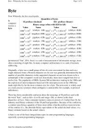
G1<br />
X G1 =J0.2<br />
X 12 =J0.8<br />
G2<br />
X G2 = J0.4<br />
Bus 1<br />
Bus 2<br />
X 13 = J0.4<br />
X 23 = J0.4<br />
Bus 3<br />
Figure 1<br />
Solution<br />
The fault is simulated by switching on an impedance Z f at bus 3 as shown in the figure<br />
below:<br />
G1<br />
X G1 =J0.2<br />
X 12 =J0.8<br />
G2<br />
X G2 = J0.4<br />
Bus 1<br />
Bus 2<br />
X 13 = J0.4<br />
X 23 = J0.4<br />
Bus 3<br />
Z f =J0.16<br />
By Thevenin’s theorem, the changes in the network voltage due to the fault impedance<br />
Z f can be represented by a voltage source V th with all other voltage sources short<br />
circuited as shown below:<br />
2