SECTION 1 / AFDELING 1 - MEMO Question 1: Give the following ...
SECTION 1 / AFDELING 1 - MEMO Question 1: Give the following ...
SECTION 1 / AFDELING 1 - MEMO Question 1: Give the following ...

You also want an ePaper? Increase the reach of your titles
YUMPU automatically turns print PDFs into web optimized ePapers that Google loves.
<strong>SECTION</strong> 1 / <strong>AFDELING</strong> 1 - <strong>MEMO</strong><br />
FW LEUSCHNER<br />
Xformers & Electrical Machines / Xformators & Elektriese Masjiene<br />
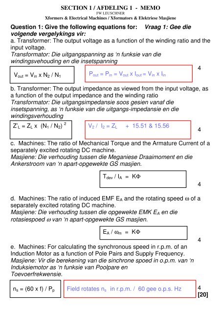
<strong>Question</strong> 1: <strong>Give</strong> <strong>the</strong> <strong>following</strong> equations for: Vraag 1: Gee die<br />
volgende vergelykings vir:<br />
a. Transformer: The output voltage as a function of <strong>the</strong> winding ratio and <strong>the</strong><br />
input voltage.<br />
Transformator: Die uitgangspanning as ‘n funksie van die<br />
windingsvehouding en die insetspanning<br />
4<br />
Vout = Vin x N2 / N1<br />
Pout = Pin = Vout x Iout = Vin x Iin<br />
b. Transformer: The output impedance as viewed from <strong>the</strong> input voltage, as<br />
a function of <strong>the</strong> output impedance and <strong>the</strong> winding ratio<br />
Transformator: Die uitgangsimpedansie soos gesien vanaf die<br />
insetspanning, as ‘n funksie van die uitgangs-impedansie en die<br />
windingsverhouding<br />
Z’L = ZL x (N1 / N2) 2<br />
c. Machines: The ratio of Mechanical Torque and <strong>the</strong> Armature Current of a<br />
separately excited rotating DC machine.<br />
Masjiene: Die verhouding tussen die Meganiese Draaimoment en die<br />
Ankerstroom van ‘n apart-opgewekte GS masjien.<br />
d. Machines: The ratio of induced EMF EA and <strong>the</strong> rotating speed ω of a<br />
separately excited rotating DC machine.<br />
Masjiene: Die verhouding tussen die opgewekte EMK EA en die<br />
rotasiespoed ω van ‘n apart-opgewekte GS masjien.<br />
e. Machines: For calculating <strong>the</strong> synchronous speed in r.p.m. of an<br />
Induction Motor as a function of Pole Pairs and Supply Frequency.<br />
Masjiene: Vir die berekening van die sinchrone spoed in o.p.m. van ‘n<br />
Induksiemotor as ‘n funksie van Poolpare en<br />
Toevoerfrekwensie.<br />
ns = (60 x f) / Pp<br />
V2 / I2 = ZL + 15.51 & 15.56<br />
Tdev / IA = KΦ<br />
EA / ωm = KΦ<br />
Field rotates ns in r.p.m. / 60 gee o.p.s. Hz<br />
4<br />
4<br />
4<br />
4<br />
[20]
<strong>Question</strong> 2 / Vraag 2<br />
An electric vehicle (battery powered) is running uphill at constant speed and<br />
constant field current (separately excited DC machine).<br />
What happens when <strong>the</strong> vehicle runs down <strong>the</strong> o<strong>the</strong>r side of <strong>the</strong> hill (no<br />
change in field current or speed)?<br />
‘n Elektriese voertuig (aangedryf deur batterye) ry op teen ‘n bult teen ‘n<br />
konstante spoed en konstante veldstroom (apart opgewekte GS masjien.<br />
Wat gebeur wanneer die voertuig teen die anderkant van die bult afry (geen<br />
verandering in veldstroom of spoed)?<br />
Uphill / opdraend:<br />
Battery voltage = VB and EA = VB - ( IA x RA)<br />
EA = KΦωm ∴ωm = constant & Φ = constant ∴ EA = constant<br />
and < VB IA = constant ∴ Tdev = constant & P = constant<br />
Down hill / afdraend:<br />
IF = constant ∴ Φ = constant and K = constant. Assume ωm =<br />
constant ∴ same speed and wind losses<br />
∴ Tdev = constant in opposite direction (generator) i.e. Tinput to<br />
Rotor. Tin = KΦIA ∴ IA = Tin / KΦ in opposite direction but<br />
constant.<br />
∴ VB = EA + ( IA x RA) ∴ Battery gets charged at VB and IA ⇒<br />
NOTE: I A is now negative (∴ EA > VB )<br />
Assume constant battery voltage ???)<br />
<strong>Question</strong> 3 / Vraag 3<br />
For a three-phase squirrel cage induction motor, <strong>the</strong> <strong>following</strong> is known:<br />
Supply voltage 400V (line voltage). Frequency 50 Hz. Delivered output<br />
power 10kW at 20A input current and 0.75 power factor.<br />
What is? i. The electrical input power into <strong>the</strong> motor. ii. The efficiency of<br />
<strong>the</strong> motor in %. iii. The values of three capacitors to be connected across<br />
<strong>the</strong> three phase connections on <strong>the</strong> motor – namely A, B and C to<br />
improve <strong>the</strong> power factor to 0.90<br />
i.<br />
PIn = √3 VLine x I x cosθ = 10.39kW<br />
(3)<br />
ii.<br />
η = ( Pout / Pin ) x 100 = 96.2%<br />
(3)<br />
iii. Change PF from .75 to 0.90 by adding one capacitor across<br />
each line voltage. Total Qin = √3 VLine x I x sinθ = 9.17kVAr (9)<br />
For PF to be 0.90 we need cosθ = 0.90 or θ = 25.84° and Qin’ =<br />
√3 VLine x I x sinθ = 6.04kVAr<br />
∴ Add Q =3.13kVAr Capacitive or QEach = 1.04kVAr per phase.<br />
Q = VLine<br />
[15]<br />
2 / XC ∴ XC = VLine 2 / Q = 153.8Ω and<br />
XC = 1 / 2πfC ∴ C = 1 / 2πf XC = 20.7 µF<br />
[10]