
You also want an ePaper? Increase the reach of your titles
YUMPU automatically turns print PDFs into web optimized ePapers that Google loves.
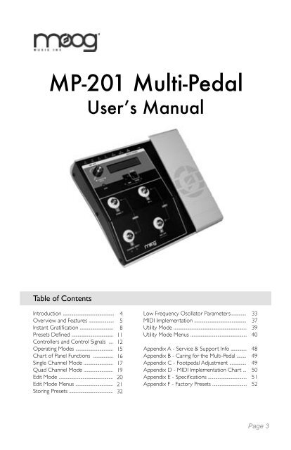
<strong>MP</strong>-<strong>201</strong> Multi-Pedal<br />
Userʼs <strong>Manual</strong><br />
Table of Contents<br />
Introduction .................................................<br />
Overview and Features ........................<br />
Instant Gratification ................................<br />
Presets Defined ........................................<br />
Controllers and Control Signals ....<br />
Operating Modes ....................................<br />
Chart of Panel Functions ...................<br />
Single Channel Mode ............................<br />
Quad Channel Mode ............................<br />
Edit Mode ....................................................<br />
Edit Mode Menus ....................................<br />
Storing Presets ..........................................<br />
4<br />
5<br />
8<br />
11<br />
12<br />
15<br />
16<br />
17<br />
19<br />
20<br />
21<br />
32<br />
Low Frequency Oscillator Parameters...............<br />
MIDI Implementation ..................................................<br />
Utility Mode ......................................................................<br />
Utility Mode Menus ......................................................<br />
Appendix A - Service & Support Info ...............<br />
Appendix B - Caring for the Multi-Pedal .........<br />
Appendix C - Footpedal Adjustment ................<br />
Appendix D - MIDI Implementation Chart ...<br />
Appendix E - Specifications .....................................<br />
Appendix F - Factory Presets .................................<br />
33<br />
37<br />
39<br />
40<br />
48<br />
49<br />
49<br />
50<br />
51<br />
52<br />
Page 3
<strong>MP</strong>-<strong>201</strong> User’s <strong>Manual</strong><br />
Introduction<br />
Thank you and congratulations on your purchase of the <strong>MP</strong>-<strong>201</strong> Multi-Pedal. The<br />
<strong>MP</strong>-<strong>201</strong> Multi-Pedal is an advanced four-channel CV/MIDI footpedal controller.<br />
The analog CV control outputs consist of four 1⁄4” jacks located on the back of<br />
the unit. The MIDI I/O consists of both USB and DIN MIDI connectors. The signals<br />
at the outputs are determined by the settings of the four Control Channels, each<br />
programmed in a Preset. Each Control Channel features an analog control output<br />
and can simultaneously transmit MIDI Continuous Controller and Program Change<br />
messages on an assignable MIDI Channel.<br />
The <strong>MP</strong>-<strong>201</strong> Multi-Pedal allows you to perform real-time performance gestures<br />
and musical nuances that would otherwise require the coordinated efforts of<br />
many hands and feet to achieve. It is designed to work with the complete line of<br />
<strong>Moog</strong>erfooger Analog effects, as well as our Voyager and Little Phatty synthesizers,<br />
and other Control Voltage (CV) and MIDI-compatible devices, or software.<br />
The following pages provide descriptions of the operation, features, and the programmable<br />
options of the <strong>MP</strong>-<strong>201</strong>. At the end of this booklet you’ll find technical<br />
specifications, service and warranty information, and contact information if should<br />
you need to reach us.<br />
To get started right away, refer to the Instant Gratification section on page 8.<br />
Package Contents<br />
The <strong>MP</strong>-<strong>201</strong> Multi-Pedal is shipped with the following items:<br />
Page 4<br />
1. The <strong>MP</strong>-<strong>201</strong> Multi-Pedal<br />
2. Power Adapter (12VAC, 500mA output)<br />
3. User’s <strong>Manual</strong><br />
4. 2.5mm Allen Wrench (for adjusting the footpedal)<br />
In addition to the <strong>MP</strong>-<strong>201</strong> Multi-Pedal and provided accessories, you will need to<br />
supply:<br />
1. An analog CV or MIDI-capable instrument or device<br />
2. Patch cords and/or MIDI cords<br />
NOTE: Be sure to review and understand the input specifications of<br />
any equipment to be controlled by the <strong>MP</strong>-<strong>201</strong> before connecting to<br />
ensure compatibility.
Overview and Features<br />
<strong>MP</strong>-<strong>201</strong> User’s <strong>Manual</strong><br />
The <strong>MP</strong>-<strong>201</strong> Multi-Pedal has 4 analog Control Voltage (CV) outputs and USB/<br />
standard MIDI connectors that can transmit or receive controller information on up<br />
to 4 MIDI channels simultaneously.<br />
Each CV output can be individually programmed as an analog CV with +/- 5V limits,<br />
or a Gate trigger (0V - 5V). The analog CV outputs can be:<br />
- A footpedal-controlled voltage that changes smoothly from a<br />
user-programmed heel value to a user-programmable toe value<br />
- An LFO with user-selected Waveform, Rate, Offset and Amount.<br />
LFO signals can be free running or can be synced to MIDI Clock,<br />
Tap Tempo, or each other. The LFO Footpedal Mode selects the<br />
adjustment of LFO Rate , Amount or Offset with the footpedal<br />
- Random Noise. The LFO Footpedal Mode selects the adjustment<br />
of Noise Amount or Offset with the footpedal.<br />
MIDI controller information can be any combination of up to four MIDI Continuous<br />
Controller (CC) messages (0 – 127) on up to four MIDI channels (one CC per<br />
channel). The <strong>MP</strong>-<strong>201</strong> can also receive MIDI CCs on its assigned MIDI Channels<br />
and output analog CVs based on the CC Values.<br />
A collection of four programmed Channels (CV and MIDI) is a Preset. There are<br />
50 Presets available.<br />
The <strong>MP</strong>-<strong>201</strong> Multi-Pedal offers four modes of operation:<br />
- Single Channel Mode is a performance mode. The footswitches are<br />
used to select programs and channels, turn channels ON/OFF, select<br />
the tap tempo function, and enter tap tempo. The footpedal affects all<br />
Channels that are ON.<br />
- Quad Channel Mode is a performance mode. The footswitches are<br />
used to turn Channels 1–4 ON/OFF, or select the tap tempo function.<br />
The footpedal affects all Channels that are ON.<br />
- Edit Mode provides access to editing menus where you can program<br />
the various parameters that make up a Preset.<br />
- Utilities Mode provides access to non-Preset related functions, such as<br />
SysEx Transfers, Firmware Upgrades, Footpedal Calibrations, etc.<br />
Page 5
<strong>MP</strong>-<strong>201</strong> User’s <strong>Manual</strong><br />
Here’s a brief look at the <strong>MP</strong>-<strong>201</strong> front and back panel controls and functions:<br />
Front Panel:<br />
1. VALUE encoder/Encoder Pushswitch - The VALUE encoder selects presets<br />
and is used to navigate through editing screens. Rotating the VALUE<br />
encoder changes presets, parameters and values. Pressing the Encoder<br />
Pushswitch moves the cursor.<br />
2. Two-line LCD Display (16 characters/line)<br />
3. EDIT and ENTER/STORE Buttons - for editing and storing Presets. Pressing<br />
both buttons simultaneously displays the Utilities menu, where you can<br />
change global settings and perform functions such as saving presets and<br />
updating the firmware.<br />
4. ‘Gas pedal’ style footpedal controller<br />
5. Four momentary footswitches (FS1-FS4). These switches are used to select<br />
Presets, turn channels ON/OFF, select modes and set the desired tempo<br />
(tap tempo).<br />
Page 6
<strong>MP</strong>-<strong>201</strong> User’s <strong>Manual</strong><br />
6. Four Footswitch LED indicators. The Bi-color LED indicators are used to display<br />
the current ON/OFF state of the four outputs (Red LEDs) and the current<br />
level of the outputs (Amber LEDs).<br />
7. MIDI LED - Indicates MIDI Input activity when lit.<br />
Back Panel:<br />
NOTE: The chart on page 16 details the function of the panel controls<br />
in all modes of operation, and is a handy reference for learning how to<br />
navigate through the <strong>MP</strong>-<strong>201</strong>’s functions.<br />
1. Power Switch and Adapter Socket – provides power to the <strong>MP</strong>-<strong>201</strong>.<br />
Power is ON when the switch is depressed.<br />
NOTE: The <strong>MP</strong>-<strong>201</strong> requires 12VAC power, 0.5A, which is provided by<br />
the included power supply unit (PSU). Do not attempt to use other PSUs<br />
with this unit - doing so may damage the <strong>MP</strong>-<strong>201</strong>.<br />
2. USB connector - B-type USB connector that provides USB MIDI functionality<br />
when connected to a Windows XP/Vista or Mac OSX computer with<br />
MIDI-compatible Software<br />
3. MIDI In and Out connectors – for MIDI In and Out connections to<br />
other MIDI devices.<br />
4. Four CV outputs (CV1 - CV4) on standard 1⁄4” TS jack sockets.<br />
Page 7
<strong>MP</strong>-<strong>201</strong> User’s <strong>Manual</strong><br />
Instant Gratification<br />
Follow these steps to experience some of what the <strong>MP</strong>-<strong>201</strong> Multi-Pedal can do.<br />
Unpack and set up the Multi-Pedal. Connect the supplied AC adapter to the POW-<br />
ER IN jack on the back of the Multi-Pedal, and then make additional connections as<br />
shown. For CV connections, use a standard 1⁄4“ patch cord. For MIDI connections,<br />
use a standard MIDI DIN cable<br />
For Analog CV Control -<br />
Page 8<br />
1. If you plan to use the Multi-Pedal with a Minimoog Voyager or Little<br />
Phatty setup, plug the other end of the patch cord in the FILTER input<br />
jack. Select a highly resonant patch, and turn the instrument’s FILTER<br />
CUTOFF knob to a low setting.<br />
If you plan to use the Multi-Pedal with a <strong>Moog</strong>erfooger Pedal, set things<br />
up as you normally would with your instrument, and then plug the<br />
other end of the patch cord into one of the following <strong>Moog</strong>erfooger<br />
pedal jacks:<br />
MF-101: Plug into the CUTOFF jack, and set the FILTER CUTOFF<br />
knob to a low setting. Set the resonance fairly high.<br />
MF-102: Plug into the FREQ jack. Set the FREQ knob CCW.<br />
MF-103: Plug into the RATE jack. Set the RATE knob CCW.<br />
MF-104: Plug into the TIME jack. Set the TIME knob CCW.<br />
MF-105: Plug into the RATE jack. Set the RATE knob to 12:00.<br />
MF-107: Plug into the FREQ jack. Set the FREQ knob CCW.<br />
2. Adjust your monitoring (amp or headphones) for a comfortable<br />
listening level.
<strong>MP</strong>-<strong>201</strong> User’s <strong>Manual</strong><br />
3. On the Multi-Pedal, use the VALUE encoder to select Preset 00<br />
‘EXPRESSR’. The Multi-Pedal LCD should appear as shown below.<br />
The Multi-Pedal is now configured as a<br />
standard expression pedal with a Control<br />
Voltage (CV) range of 0 to +5V. If you are<br />
connected to a Voyager or Little Phatty,<br />
playing the keyboard while adjusting the<br />
footpedal will open and close the filter. If<br />
you are connected to a <strong>Moog</strong>erfooger<br />
pedal, playing your instrument while adjusting<br />
the footpedal will change the related<br />
<strong>Moog</strong>fooger parameter (Cutoff, Rate, Freq,<br />
etc.).<br />
4. On the Multi-Pedal, use the VALUE encoder to select Preset 01<br />
‘REVERSE4’. This time the Multi-Pedal is configured as expression<br />
pedal that works in reverse, where the maximum value is in the heel<br />
position and the minimum value is the toe position.<br />
5. On the Multi-Pedal, use the VALUE encoder to select Preset 02<br />
‘TRIANGLE’. The Multi-Pedal is now configured to output a Low<br />
Frequency Oscillator (LFO) Triangle wave CV where the footpedal<br />
is configured to control the speed (RATE) of the LFO.<br />
6. Presets 03 thru 08 offer variations of LFOs (square, sawtooth,<br />
sample & hold, etc.). Feel free to experiment with all of them, and<br />
then try some different patch routings with the <strong>Moog</strong>erfoogers or<br />
Voyager/Little Phatty.<br />
For MIDI Control -<br />
If you are a MIDI musician, try the following example:<br />
1. Plug the other end of the MIDI cord from the <strong>MP</strong>-<strong>201</strong> to the MIDI IN<br />
jack of your MIDI Instrument or MIDI Device.<br />
Page 9
<strong>MP</strong>-<strong>201</strong> User’s <strong>Manual</strong><br />
These simple examples only serve to familiarize you with the <strong>MP</strong>-<strong>201</strong> Multi-Pedal in<br />
a very basic way. When you realize that the <strong>MP</strong>-<strong>201</strong>’s four Channels, each consisting<br />
of an Analog CV and MIDI CC, can be individually configured and controlled<br />
simultaneously, you can begin to appreciate the many creative control possibilities<br />
the <strong>MP</strong>-<strong>201</strong> Multi-Pedal can provide.<br />
Page 10<br />
2. On the Multi-Pedal, use the VALUE encoder to select Preset 33,<br />
‘MIDI CCs’. The Multi-Pedal LCD should appear as shown below.<br />
The Multi-Pedal is now configured as an<br />
expression pedal that is setup to transmit<br />
MIDI CC messages for Mod Wheel (CC#1),<br />
Breath (CC#2), Volume (CC#7) and Foot-<br />
Ctl (CC#4) on MIDI Channel 1. If your<br />
MIDI device is setup to receive MIDI CC’s<br />
on MIDI channel 1, moving the footpedal will<br />
have the same effect as moving the Modulation<br />
Wheel on a MIDI keyboard controller.<br />
Consult the documentation that came with<br />
your MIDI Instrument or MIDI Device for<br />
additional configuration information.<br />
NOTE: Adventurous users are encouraged to grab a few more patch<br />
cords and check out the Factory Presets that appear in Appendix F. The<br />
Factory Presets include specific setups for the Voyager and Little Phatty<br />
synthesizers, as well as setups for <strong>Moog</strong>erfooger pedals (MF101 thru<br />
MF107), MIDI setups, and more.<br />
Connecting your <strong>MP</strong>-<strong>201</strong> to computer via USB<br />
The <strong>MP</strong>-<strong>201</strong> can perform MIDI In/Out functions over a USB cable on either a<br />
Windows XP/Vista computer or a Macintosh OSX computer. The <strong>MP</strong>-<strong>201</strong> uses<br />
standard drivers, so it does not require you to install any special software prior to use.<br />
Before you start the MIDI application you wish to control with your <strong>MP</strong>-<strong>201</strong>, simply<br />
connect the <strong>MP</strong>-<strong>201</strong> to the computer with a USB cable. If you are using a Windowsbased<br />
PC, the computer will acknowledge that it has recognized the <strong>MP</strong>-<strong>201</strong> as a<br />
USB Composite Device and as a USB Audio Device, and will inform you when the<br />
hardware is installed and ready to use (for Mac users, the Multi-Pedal is ready to be<br />
used as soon as it is plugged in). Once the Multi-Pedal is connected via USB, you may<br />
start your MIDI application and select the <strong>MP</strong>-<strong>201</strong> Multi-Pedal as a MIDI Input or<br />
Output device for that program. Be sure not to echo the application’s MIDI In to its<br />
MIDI Out, as a MIDI loop is then formed, and unpredictable results can follow.
Presets Defined<br />
<strong>MP</strong>-<strong>201</strong> User’s <strong>Manual</strong><br />
A Preset is a collection of four programmed Control Channels (see figure below).<br />
Each channel can be programmed to specify a Control Voltage (CV), a MIDI<br />
Continuous Controller message, or both. There are a total of 50 presets available<br />
(Preset #00-49).<br />
Presets can be named (8 characters max.), and each Channel in a Preset can have<br />
it’s own name (8 characters max). The Channels in a Preset can be individually<br />
switched ON or OFF, and be programmed for any one of three Channel Modes:<br />
Expression (expression pedal operation), Gate (ON/OFF trigger operation) or LFO<br />
(modulation control).<br />
Presets are selected by using the VALUE encoder, by Footswitches, or remotely by<br />
MIDI Program Change messages (when connected to a MIDI device). If Presets are<br />
selected manually, when the highest Preset value is reached (Preset #49), advancing<br />
the value once more wraps back to Preset #00.<br />
When a Preset is selected, the initial values, initial ON/OFF state and MIDI program<br />
change messages that are assigned in the Preset are output.<br />
Page 11
<strong>MP</strong>-<strong>201</strong> User’s <strong>Manual</strong><br />
Controllers and Control Signals<br />
A controller is a device that does not make any sound on its own, but is used to<br />
control another sound producing device (like a synthesizer), or a sound altering<br />
device (such as an effects module). Some devices respond to analog control signals,<br />
called Control Voltages (CVs) and Gates, and some devices respond to digital control<br />
messages through MIDI (<strong>Music</strong>al Instrument Digital Interface) commands. Some<br />
devices, such as the <strong>Moog</strong> Little Phatty®, respond to both.<br />
When we talk about controlling a sound-producing device, it can be as simple as<br />
adjusting the volume of the device with a knob. In this case think of the control as the<br />
signal produced by the knob that tells the device’s electronic ‘innards’ what the volume<br />
should be – as the control signal goes lower (by turning the knob down) the volume<br />
goes lower. As the control signal goes higher (by turning the knob up) the volume<br />
goes higher. This is an imaginary example, but it illustrates how, with a control signal,<br />
you can alter the sound (in this case the volume) of a sound-producing device.<br />
Analog Control Signals: CVs and Gates.<br />
CV stands for Control Voltage. Voltage is the measurement of electrical potential; the<br />
unit is Volts (V). When a circuit is Voltage-Controlled, it has inputs that receive a CV<br />
and turn it into a setting for a parameter such as pitch or volume. The Voltages and<br />
Currents used for most CV gear are relatively small and not dangerous, but there is<br />
not a standard for what voltage levels are used. The <strong>MP</strong>-<strong>201</strong> outputs 0V to +5V in<br />
Unipolar Mode (the default), and -5V to +5V in Bipolar Mode (see the CV SCALE<br />
menu, page 40). It is up to the <strong>MP</strong>-<strong>201</strong> user to know and understand the input<br />
requirements of their analog gear before connecting the <strong>MP</strong>-<strong>201</strong>. Some analog gear<br />
may not be able to accept negative voltages! All current <strong>Moog</strong> gear is compatible with<br />
the CV outputs of the <strong>MP</strong>-<strong>201</strong>, including all <strong>Moog</strong>erfooger® Analog Effects, Minimoog<br />
Voyager® Synthesizer and the Little Phatty® Synthesizer.<br />
A CV can be produced by rotating a rotary control, or in the case of the <strong>MP</strong>-<strong>201</strong><br />
when used as in Expression Mode, by changing the position of the footpedal. This type<br />
of CV can be used for smooth, precise and expressive changes.<br />
A CV can also be produced automatically by a function known as a Low Frequency<br />
Oscillator (LFO). An oscillator is a circuit that goes up and down at a regular time<br />
interval with a repeating shape, known as a Waveform. The RATE at which the LFO<br />
goes up and down is the frequency. The LFO is low frequency because it produces<br />
vibrations lower than the human ear can hear. We can hear vibrations as low in<br />
frequency as 20 times per second or 20 Hertz (Hz). The <strong>MP</strong>-<strong>201</strong> can produce LFO<br />
signals from .1 Hz to 1000 Hz. At lower rates, effects can include tremolo, vibrato,<br />
Page 12
<strong>MP</strong>-<strong>201</strong> User’s <strong>Manual</strong><br />
trills, or slow rhythmic sweeps, while oscillations in the audio range can be used<br />
to create truly wild sonic effects, including frequency modulation (FM), amplitude<br />
modulation (AM), and timbre modulation.<br />
A CV can also be a randomly generated signal. If it is continuously random, it is called<br />
Noise, similar to the static white noise that can be picked up on an analog radio<br />
tuned between stations. If it is a random voltage that changes only at regular periodic<br />
intervals, then we refer to this type of voltage as Sample and Hold, or S+H.<br />
The <strong>MP</strong>-<strong>201</strong> offers a number of LFO waveforms as shown in the figure below. Each<br />
graph shows the way the voltage varies with time.<br />
Triangle waveform Square waveform Ramp waveform<br />
Sawtooth waveform Sample & Hold<br />
waveform<br />
The height of the LFO waveform shows its amplitude. In the <strong>MP</strong>-<strong>201</strong>, this parameter<br />
is called the ‘LFO AMOUNT’<br />
The center of the LFO waveform (along the horizontal axis) can be shifted up or<br />
down by means of an offset voltage. This means that you can have a LFO centered<br />
around 0V, or shifted up and centered around +2.5V, for example. In the <strong>MP</strong>-<strong>201</strong>, this<br />
parameter is called the ‘LFO OFFSET.’<br />
Finally, a Gate is a type of analog control signal that is either low or high, and changes<br />
abruptly, not smoothly. A Gate is used to trigger events, or to turn circuits ON or OFF.<br />
The <strong>MP</strong>-<strong>201</strong> outputs a Gate that is 0V = OFF and +5V = ON.<br />
Gate: OFF ON OFF<br />
Noise<br />
Page 13
<strong>MP</strong>-<strong>201</strong> User’s <strong>Manual</strong><br />
MIDI<br />
MIDI was developed as a standard way of communicating control signals digitally for<br />
musical devices or software across a MIDI or USB cable. Standard MIDI cables use 5-pin<br />
DIN connectors, and each cable can send MIDI data (MIDI OUT) or receive MIDI Data<br />
(MIDI IN). USB Cables combine both MIDI In and MIDI Out functions. MIDI data is<br />
sent as Messages. There are two categories of messages: Channel messages and System<br />
Messages.<br />
MIDI allows for up to 16 MIDI Channels on each MIDI Cable – thus Channel messages<br />
are assigned to one of sixteen MIDI Channels. The different channels can be used to<br />
address different devices, or different sounds or sound parameters within a single device.<br />
Types of Channel Messages include Note On/Note Off (not used in the <strong>MP</strong>-<strong>201</strong>),<br />
Program Change Messages (used to select presets in a device) or Continuous Controller<br />
(CC) Messages. CC Messages are like the CVs of MIDI – they are a control signal with<br />
128 levels. In many MIDI devices, CCs can be used in a manner akin to a CV, changing<br />
pitch or volume for example.<br />
A System Message is a general message and does not address a particular channel. A<br />
System Exclusive (SysEx) message is a type of System message that is defined only for<br />
a particular device, so that other devices will ignore it. That could be the settings of a<br />
particular preset, or the collected settings of a bank of presets, or it could be a larger file<br />
such as a firmware file that updates the operating system of the device. A MIDI CLOCK<br />
message is a type of System Message that is a REAL TIME message and provides tempo<br />
information to other MIDI devices. There are 24 MIDI Clock messages transmitted for<br />
every quarter note. The <strong>MP</strong>-<strong>201</strong> can be set to sync LFOs to various time divisions of a<br />
current tempo by MIDI clock messages.<br />
Please note that though MIDI is a standard communications protocol, it is old (published<br />
in 1983), serial (sends one message after the other), and slow (31.25 Kbaud). The <strong>MP</strong>-<br />
<strong>201</strong> can send out a lot of MIDI data at once, especially when a Preset Channel is set as<br />
an LFO. Some devices and software may not handle this data in a predictable way. It<br />
is up to the user to know and understand the MIDI implementation of a device before<br />
connecting it to the <strong>MP</strong>-<strong>201</strong>. Also be aware that MIDI loops (connecting MIDI In to<br />
MIDI Out on two devices) may occur when using the <strong>MP</strong>-<strong>201</strong> with sequencer software.<br />
This should be avoided, especially when using the MIDI USB connection, as MIDI loops<br />
can cause unpredictable behavior.<br />
Page 14
Operating Modes<br />
<strong>MP</strong>-<strong>201</strong> User’s <strong>Manual</strong><br />
The controls on the Multi-Pedal perform multiple functions as indicated on the front<br />
panel of the unit. In order to organize these functions into logical groups, the Multi-<br />
Pedal uses the concept of ‘Operating Modes’. There are four Operating Modes:<br />
- Single Channel (SGL) Mode<br />
- Quad Channel (QD) Mode<br />
- Edit Mode<br />
- Utilities Mode<br />
The Single Channel and Quad Channel modes are the Performance Modes, where<br />
the Multi-Pedal footpedal and footswitches is employed as a performance controller.<br />
The Edit and Utility Modes are the Programming Modes, where you specify Preset<br />
parameters and perform global and System Exclusive operations.<br />
The figure below shows the relationship of the four Operating Modes. Navigation<br />
between modes is performed via the panel buttons and footswitches. Pressing FS1<br />
and FS3 together toggles between Performance Modes (SGL, QD). Pressing the<br />
EDIT button, or FS2 and FS4 together, places you in Edit Mode. Pressing the EDIT<br />
and ENTER buttons simultaneously places you in Utilities Mode. The Edit and Utilities<br />
Modes are accessible from any other mode as shown. Note that once you are in Edit<br />
or Utilities Mode, you will be returned to the previous operating mode when you exit.<br />
For example, if you entered Edit Mode from SGL Mode, you will return to SGL Mode<br />
when you exit.<br />
Detailed descriptions of the four Operating Modes follows. A table showing the<br />
Multi-Pedal panel control functions for the various Operating Modes appears on the<br />
next page.<br />
Multi-Pedal Operating Modes<br />
Page 15
<strong>MP</strong>-<strong>201</strong> User’s <strong>Manual</strong><br />
Page 16<br />
<br />
<br />
<br />
<br />
<br />
<br />
<br />
<br />
<br />
<br />
<br />
<br />
<br />
<br />
<br />
<br />
<br />
<br />
<br />
<br />
<br />
<br />
<br />
<br />
<br />
<br />
<br />
<br />
<br />
<br />
<br />
<br />
<br />
<br />
<br />
<br />
<br />
<br />
<br />
<br />
<br />
<br />
<br />
<br />
<br />
<br />
<br />
<br />
<br />
<br />
<br />
<br />
<br />
<br />
<br />
<br />
<br />
<br />
<br />
<br />
<br />
<br />
<br />
<br />
<br />
<br />
<br />
<br />
<br />
<br />
<br />
<br />
<br />
<br />
<br />
<br />
<br />
<br />
<br />
<br />
<br />
<br />
<br />
<br />
<br />
<br />
<br />
<br />
<br />
<br />
<br />
<br />
<br />
<br />
<br />
<br />
<br />
<br />
<br />
<br />
<br />
<br />
<br />
<br />
<br />
<br />
<br />
<br />
<br />
<br />
<br />
<br />
<br />
<br />
<br />
<br />
<br />
<br />
<br />
<br />
<br />
<br />
<br />
<br />
<br />
<br />
<br />
<br />
<br />
<br />
<br />
<br />
<br />
<br />
<br />
<br />
<br />
<br />
<br />
<br />
<br />
<br />
<br />
<br />
<br />
<br />
<br />
<br />
<br />
<br />
<br />
<br />
<br />
<br />
<br />
<br />
<br />
<br />
<br />
<br />
<br />
<br />
<br />
<br />
<br />
<br />
<br />
<br />
<br />
<br />
<br />
<br />
<br />
<br />
<br />
<br />
<br />
<br />
<br />
<br />
<br />
<br />
<br />
<br />
<br />
<br />
<br />
<br />
<br />
<br />
<br />
<br />
<br />
<br />
<br />
<br />
<br />
<br />
<br />
Multi-Pedal Panel Controls
Single Channel Mode<br />
<strong>MP</strong>-<strong>201</strong> User’s <strong>Manual</strong><br />
Single Channel Mode is the default operation mode when the Multi-Pedal is first<br />
powered up. Single Channel Mode (SGL) allows you to:<br />
- view and edit the current Preset name,<br />
- view information about the current Channel<br />
- select the current Preset with footswitches.<br />
In SGL Mode, the movement of the footpedal will affect any of the channels that are<br />
ON in the manner defined by the Channel Mode and settings of the Channels in<br />
the preset. The bottom two footswitches (FS3 & FS4) select and turn ON/OFF the<br />
individual Channels, while the top two footswitches (FS1 & FS2) select the Presets.<br />
LCD Display<br />
In SGL Mode , the top line of the LCD displays the Preset Name and Number, while<br />
the bottom line displays the current Channel information. The bottom right corner<br />
of the display defaults to displaying the Channel name, but can also be set to display a<br />
precision value, an MIDI CC value, or the output voltage (see the Display Units menu<br />
on page 42 for more information).<br />
Footswitch Indicators<br />
The Footswitch Bi-color LED indicators 1-4 correspond to the current Preset’s<br />
channel outputs. They show which channels are ON or OFF using a Red LED and the<br />
current output level using variable brightness Amber LEDs.<br />
Page 17
<strong>MP</strong>-<strong>201</strong> User’s <strong>Manual</strong><br />
Preset Names<br />
Preset Naming is only available in Single Channel Mode.<br />
Page 18<br />
To name a Preset, press the Encoder pushswitch.<br />
The cursor will move to the first letter in the Preset<br />
name field. Use the VALUE encoder to selected the<br />
desired character.<br />
Press the ENTER button to move the cursor to the<br />
next character. Use the VALUE encoder again to<br />
select the desired second character, and so forth, until<br />
all characters are chosen. When Preset naming is<br />
completed, press the Encoder pushswitch to return<br />
the cursor to the Preset Number field.<br />
NOTE: While the cursor is in the Preset Name field, the ENTER/STORE<br />
button moves the cursor to the right, while the EDIT button moves the<br />
cursor to the left. The cursor will wrap when the left-most or right-most<br />
character is reached.
Quad Channel Mode<br />
<strong>MP</strong>-<strong>201</strong> User’s <strong>Manual</strong><br />
Quad Channel Mode (QD) provides access to controlling all four channels at the<br />
same time. Each footswitch controls the ON/OFF state of the channel indicated by<br />
the Channel number. The movement of the footpedal will affect any of the Channels<br />
that are ON in the manner defined by the Channel Mode and settings of the Channels<br />
in the preset.<br />
Quad Channel Mode provides:<br />
- instant access to turning any of the four channels ON/OFF.<br />
- viewing the status of all four Channels at once<br />
- fast access to the Tap Tempo functions on all four channels (if applicable).<br />
LCD Display<br />
In Quad Channel Mode, the top line of the LCD displays “QD”: the current<br />
Operating Mode, and the status of Channels 1& 2, while the bottom line displays<br />
the current preset number and the status of Channels 3 & 4 as shown below. In the<br />
factory default configuration (DISPLAY UNITS = OFF), the LCD displays the Channel<br />
Modes (Expression, Gate or LFO), but this can be programmed to show the actual<br />
CV values instead .<br />
Footswitch Indicators<br />
The Footswitch Bi-color LED indicators 1-4 correspond to the current preset’s<br />
channel outputs. They show which channels are ON or OFF using a Red LED and the<br />
current output level using variable brightness Amber LEDs<br />
Page 19
<strong>MP</strong>-<strong>201</strong> User’s <strong>Manual</strong><br />
Edit Mode<br />
Edit Mode allows you to edit the parameters of a Preset. Edit Mode can be entered<br />
from Single Channel Mode or Quad Channel Mode simply by pressing EDIT or by<br />
pressing FS2 & FS4 simultaneously.<br />
In Edit Mode, the VALUE Encoder or footswitches 1 & 2 (FS1 and FS2) are used to<br />
scroll through the edit menus. In any menu, pressing the Encoder pushswitch or FS4<br />
moves the cursor to the bottom line of the LCD, where you can change the edit value<br />
using the VALUE Encoder. Pressing the Encoder pushswitch or FS4 again moves the<br />
cursor back to the top line of the LCD.<br />
Page 20<br />
NOTE: When the cursor appears in the value field, the footpedal<br />
is used to set Footpedal Parameter values, such as the Heel,<br />
Toe and Initial values. The VALUE encoder can be used for ‘fine’<br />
adjustments to these values.<br />
Footswitch 3 (FS3) is used to select the Channel or Preset MIDI routing for editing<br />
(CH1, CH2, CH3, CH4, or ALL). You can change the current Channel (or MIDI ALL)<br />
at any time while in Edit Mode.<br />
To exit from Edit Mode at any time, press the EDIT button again. Note that any<br />
changes made to Preset parameters are maintained until the Preset number is<br />
changed, but will be lost if you do not save them (see ‘Storing Presets’, page 32).<br />
NOTE: When you edit the ‘Heel’, ‘Toe’, an ‘Initial’ values in Expression<br />
Mode and LFO Mode, and the ‘Rate’, ‘Amount’ and ‘Offset’<br />
values in LFO Mode, the footpedal has no effect on any other<br />
Channel, or any other parameter. The CV and MIDI outputs reflect<br />
the voltage/MIDI CC values of the footpedal position, allowing you to<br />
‘hear’ what the actual values are.
Edit Mode Menus<br />
<strong>MP</strong>-<strong>201</strong> User’s <strong>Manual</strong><br />
The menu trees shown on the following pages will assist you in navigating through the<br />
available Preset editing parameters. Note that the menus are dynamic, which means<br />
that the available parameters change based on the selected Channel Mode.<br />
The menu trees show the parameters, values and descriptions for each menu item.<br />
Control Voltage values are displayed as a range from 0 – 4095 (‘PRECISION’ units<br />
- the factory default view), which represents the total programmable voltage range.<br />
If you’d rather work in volts, you can change the view from ‘PRECISION’ to ‘VOLTS’<br />
using the ‘DISPLAY UNITS’ Utilities menu (page 42).<br />
All control voltages have a total programmable range of +/-5V (bipolar). As shipped<br />
from the factory, however, the Multi-Pedal is configured for a unipolar range of 0-5V.<br />
If you wish to work with bipolar voltages, go to the ‘CV SCALE’ Utilities menu (page<br />
40) and select ‘BIPOLAR’.<br />
NOTE: The choice of CV Scale (Unipolar or Bipolar) affects all<br />
CV parameters globally.<br />
PRECISION values have a total range of 0 - 4095 regardless of whether the CV<br />
voltage range is Unipolar or Bipolar. This means that a precision value of ‘0’ can<br />
indicate either 0 Volts (in Unipolar mode), or -5V (in Bipolar mode). The tables below<br />
show the how to interpret the values:<br />
UNIPOLAR<br />
Value = Volts Value = Precision<br />
0 0<br />
+1.25 1024<br />
+2.50 2048<br />
+3.75 3072<br />
+5.00 4095<br />
BIPOLAR<br />
Value = Volts Value = Precision<br />
-5.00 0<br />
-2.50 1024<br />
0 2048<br />
+2.50 3072<br />
+5.00 4095<br />
Page 21
<strong>MP</strong>-<strong>201</strong> User’s <strong>Manual</strong><br />
EDIT Mode menus - Common Parameters<br />
><br />
PARAMETERS:<br />
Page 22<br />
:<br />
><br />
VALUES:<br />
Available character set (numbers, upper<br />
case, lower case), 8 characters max.<br />
ON, OFF<br />
EXPRESSION, GATE, LFO<br />
OFF, 1 – 16<br />
Default: 1<br />
0 – 127<br />
Default: 1<br />
LSB 0 – 128, MSB 0 – 128<br />
Default:<br />
OFF, 0 – 128<br />
Default:
DESCRIPTION:<br />
<strong>MP</strong>-<strong>201</strong> User’s <strong>Manual</strong><br />
CHANNEL NAME allows you to specify a name for the selected channel. To enter or<br />
change a name, press the Encoder pushswitch to move to the lower line of the display,<br />
and use the VALUE knob to select the desired character. Pressing the ENTER button<br />
will advance the cursor to the next character. Continue in this manner until the desired<br />
name is complete, then press the VALUE encoder switch to move back to the top line of<br />
the display. With the cursor back on the top line of the display, rotate the VALUE knob<br />
to see more menus, or press EDIT to escape.<br />
Preset names consist of any combination of 8 letters, punctuation characters and<br />
numbers. In order, the available characters are:<br />
(Space) - . 0123456789: ABCDEFGHIJKLMNO<br />
PQRSTUVWXYZabcdefghijklmnopqrstuvwxyz<br />
The INITIAL STATE determines if the selected Channel is ON or OFF when the Preset<br />
is called up.<br />
CHANNEL MODE sets the operating mode for the selected Channel. The choice of<br />
operating mode determines the available options that follow. See the Edit Menus on<br />
following pages for the Channel Mode options.<br />
MIDI CHANNEL sets the MIDI Channel for the selected Preset Multi-Pedal Channel.<br />
MIDI CC# sets the Continuous Controller message number for the selected Preset<br />
Multi-Pedal Channel. If the Multi-Pedal Channel is set to OFF, CC messages are not<br />
sent.<br />
BANK CHANGE sets the Bank Change message that is sent when a Preset is selected.<br />
PGM CHANGE sets the Program Change message that is sent when a Preset is<br />
selected.<br />
NOTE: The <strong>MP</strong>-<strong>201</strong> Multi-Pedal is capable of sending large amounts of MIDI data<br />
on up to 4 MIDI channels simultaneously. This is especially true when LFO modes<br />
are selected. Some MIDI equipment and software may not be robust enough to<br />
handle this large amount of data. <strong>Moog</strong> <strong>Music</strong> makes no guarantees of the ability<br />
of products made by other vendors to handle this amount of MIDI data.<br />
Page 23
<strong>MP</strong>-<strong>201</strong> User’s <strong>Manual</strong><br />
EDIT Mode menus - Channel Mode<br />
When Channel Mode = EXPRESSION:<br />
PARAMETERS:<br />
Page 24<br />
> ><br />
When Channel Mode = GATE:<br />
PARAMETERS:<br />
> ><br />
VALUES:<br />
EXPRESSION, GATE, LFO<br />
0 – 4095<br />
Default: 0<br />
0 – 4095<br />
Default: 4095<br />
0 – 4095<br />
Default: 2048<br />
VALUES:<br />
EXPRESSION, GATE, LFO<br />
MOMENTARY, LATCH<br />
Default: MOMENTARY
DESCRIPTION:<br />
<strong>MP</strong>-<strong>201</strong> User’s <strong>Manual</strong><br />
When CHANNEL MODE is set to EXPRESSION, the selected Channel will output a<br />
smoothly changing voltage corresponding to the movement of the footpedal.<br />
HEEL VALUE sets the value of the selected channel’s CV output when the footpedal is<br />
in the heel (up) position.<br />
TOE VALUE sets the value of the selected channel’s CV output when the footpedal is<br />
in the toe (down) position.<br />
INITIAL VALUE sets the voltage of the selected channel’s CV output when a Preset is<br />
selected.<br />
DESCRIPTION:<br />
PERFORMANCE TIP: If the HEEL VALUE > TOE VALUE, the voltage will decrease<br />
as the footpedal moves from Heel to Toe. This reverse behavior can be used for interesting<br />
performance effects.<br />
When CHANNEL MODE is set to GATE, the selected Channel will output a Gate<br />
Trigger when the corresponding footswitch is pressed. Note that the footpedal has no<br />
effect on the output in this mode<br />
FS MODE defines the operation of the selected Channel’s footswitch: MOMENTARY<br />
(ON when pressed, OFF when released) or LATCHED (toggles ON when pressed,<br />
toggles OFF when pressed a second time).<br />
NOTES: A GATE CV is defined as 0V = OFF and +5V = ON.<br />
When FS MODE is set to ‘MOMENTARY’, pressing a footswitch momentarily toggles<br />
the value of the GATE from the INITIAL STATE value. For example, if INITIAL STATE =<br />
OFF, the GATE will normally be 0V. While the footswitch is depressed, the GATE value<br />
will be +5V. If the INITIAL STATE = ON, the GATE will normally be +5V. While the<br />
footswitch is depressed, the GATE value will be 0V.<br />
When FS MODE is set to ‘LATCH’, pressing a footswitch toggles the value of the<br />
currently set GATE output. For example, if INITIAL STATE = OFF, GATE = 0V when<br />
the preset is first loaded. On the first footswitch press, GATE = +5V. On the second<br />
footswitch press, GATE = 0V, etc.<br />
Page 25
<strong>MP</strong>-<strong>201</strong> User’s <strong>Manual</strong><br />
EDIT Mode menus - Channel Mode<br />
When Channel Mode = LFO:<br />
PARAMETERS:<br />
Page 26<br />
><br />
><br />
Continued on next page<br />
VALUES:<br />
EXPRESSION, GATE, LFO<br />
TRIANGLE, SQUARE, SAW DOWN,<br />
RA<strong>MP</strong> UP, S+H RANDOM, NOISE<br />
Default: TRIANGLE<br />
RATE, AMOUNT, OFFESET<br />
Default: RATE<br />
INITIAL, CURRENT, CONTINUOUS<br />
Default: INITIAL<br />
FREE RUNNING, TAP TE<strong>MP</strong>O,<br />
CH1– CH4, MIDI CLOCK<br />
Default: FREE RUNNING<br />
0 – 4095 (approx. 0.01 to 1000 Hz)<br />
Default: 2048
DESCRIPTION:<br />
<strong>MP</strong>-<strong>201</strong> User’s <strong>Manual</strong><br />
When CHANNEL MODE is set to LFO, the selected channel will output either an LFO<br />
CV or Noise, depending on how the LFO parameter is programmed.<br />
LFO WAVEFORM allows you to choose either the waveform of the Low Frequency<br />
Oscillator, or Noise for the selected Channel. See the section entitled Low Frequency<br />
Oscillator Parameters (page 33) for more information.<br />
FPEDAL MODE (Footpedal Mode) selects the function of the footpedal effect on the<br />
LFO for the selected channel. When RATE is selected, the footpedal controls the LFO<br />
Rate (or the MIDI Clock divider value if LFO SYNC is set to MIDI CLOCK). When<br />
AMOUNT is selected, the footpedal controls the amount of the LFO on the selected<br />
channel. When OFFSET is selected, the footpedal controls the offset of the LFO on the<br />
selected channel.<br />
LFO OFF MODE allows you to select how the Multi-Pedal responds when the LFO<br />
Channel is switched OFF from a footswitch. A setting of ‘INITIAL’ will stop the LFO<br />
when OFF, and re-start the LFO at the programmed INITIAL VALUE when switched<br />
ON. A setting of ‘CURRENT’ will hold the LFO voltage at the current (static) last<br />
value when switched OFF, and resume from that point when switched ON. A setting<br />
of ‘CONTINUOUS’ maintains the current state of the LFO (Rate, Amount and Offset)<br />
when switched OFF, and resumes from that point when switched ON. In other words,<br />
‘CONTINUOUS’ turns OFF the footpedal control of the LFO, while continuing to<br />
output the LFO waveform.<br />
LFO SYNC selects the source for the LFO rate. See the section entitled Low Frequency<br />
Oscillator Parameters (page 33) for more information.<br />
LFO RATE sets the initial LFO rate for the selected channel when a Preset is selected<br />
(if no Sync signal is available). See the section entitled Low Frequency Oscillator<br />
Parameters (page 33) for more information.<br />
Page 27
<strong>MP</strong>-<strong>201</strong> User’s <strong>Manual</strong><br />
EDIT Mode menus - Channel Mode<br />
When Channel Mode = LFO (con’t):<br />
PARAMETERS:<br />
Page 28<br />
><br />
><br />
VALUES:<br />
0 – 4095<br />
Default: 4095<br />
0 – 4095<br />
Default: 2048<br />
0 – 4095<br />
Default: 0<br />
0 – 4095<br />
Default: 4095<br />
0 – 4095<br />
Default: 2048<br />
NOTE: Values displayed as 0-4095 are ‘Precision’ values. The actual<br />
representation of these values is user-programmable and can be displayed<br />
as Volts (-5 to +5V), MIDI (0 – 127) or Precision (0 – 4095). For<br />
more information, see the Display Units menu, page 42.
DESCRIPTION:<br />
<strong>MP</strong>-<strong>201</strong> User’s <strong>Manual</strong><br />
LFO AMOUNT sets the initial amount of the LFO CV for the selected Channel. See the<br />
section entitled Low Frequency Oscillator Parameters (page 33) for more information.<br />
LFO OFFSET sets the initial voltage offset amount of the LFO CV for the selected<br />
Channel.<br />
HEEL VALUE sets the value of the selected Channel’s CV output when the footpedal is<br />
in the heel (up) position.<br />
TOE VALUE sets the value of the selected Channel’s CV output when the footpedal is<br />
in the toe (down) position.<br />
INITIAL VALUE sets the value the LFO waveform starts from when first turned ON.<br />
When LFO OFF MODE = INITIAL, the INITIAL VALUE is also the value that is output<br />
when the Channel is switched OFF.<br />
Page 29
<strong>MP</strong>-<strong>201</strong> User’s <strong>Manual</strong><br />
EDIT Mode menus - MIDI ALL<br />
><br />
PARAMETERS:<br />
Page 30<br />
><br />
VALUES:<br />
GLOBAL, NONE, DIN, USB, DIN/USB<br />
Default: GLOBAL<br />
GLOBAL, NONE, DIN, USB, DIN/USB<br />
Default: GLOBAL<br />
GLOBAL, NONE, DIN OUT, USB OUT,<br />
DIN/USB OUT<br />
Default: GLOBAL<br />
GLOBAL, NONE, DIN OUT, USB OUT,<br />
DIN/USB OUT<br />
Default: GLOBAL<br />
OFF, CH1, CH2, CH3, CH4<br />
Default: OFF
DESCRIPTION:<br />
<strong>MP</strong>-<strong>201</strong> User’s <strong>Manual</strong><br />
The MIDI IN menu allows you to select the MIDI Input routing for individual Presets. The<br />
default setting is GLOBAL, which is the global MIDI IN setting from the ‘MIDI SETUP’<br />
Utilities menu (page 40). Any setting other than GLOBAL will override the Global MIDI<br />
IN setting in ‘MIDI SETUP.’<br />
The MIDI OUT menu allows you to select the MIDI Output routing for individual<br />
Presets. The default setting is GLOBAL, which is the global MIDI OUT setting from the<br />
‘MIDI SETUP’ Utilities menu. Any setting other than GLOBAL will override the Global<br />
MIDI OUT setting in ‘MIDI SETUP’.<br />
The MERGE USB IN menu allows you to select the USB Merge routing for individual<br />
Presets. The default setting is GLOBAL, which is the global USB MERGE setting from the<br />
‘MIDI SETUP’ Utilities menu. Any setting other than GLOBAL will override the Global<br />
USB MERGE setting in ‘MIDI SETUP.’<br />
The MERGE DIN IN menu allows you to select the MIDI DIN Input merge routing<br />
for individual Presets. The default setting is GLOBAL, which is the global DIN MERGE<br />
setting from the ‘MIDI SETUP’ Utilities menu. Any setting other than GLOBAL will<br />
override the Global DIN MERGE setting in ‘MIDI SETUP.’<br />
The MIDI CLOCK OUT menu allows you to select a Multi-Pedal Channel as a source for<br />
outputting MIDI Clock Messages. MIDI Clock can only be sent if the Channel selected<br />
is an LFO.<br />
Page 31
<strong>MP</strong>-<strong>201</strong> User’s <strong>Manual</strong><br />
Storing Presets<br />
The STORE function is used to save an edited Preset in Edit Mode (SAVE PRESET) or<br />
Performance Mode (SAVE PANEL).<br />
When a Preset is stored in Edit Mode, the store operation only overwrites values<br />
that have been actively edited. When a Preset is stored in Performance Mode (either<br />
Single Channel or Quad Channel Mode), the store operation overwrites initial state<br />
and value with current channel ON/OFF state and current footpedal position on any<br />
Channels that have been changed.<br />
Page 32<br />
To store a Preset, press and release the ENTER/<br />
STORE button. The LCD will display a message<br />
similar to that shown at left. The top line of the<br />
LCD displays the current Preset location, while the<br />
bottom line contains the prompt ‘SAVE PANEL? NO’<br />
(or ‘SAVE PRESET? NO’). ‘NO’ is always the default<br />
here, as it prevents you from accidently overwriting<br />
a Preset.<br />
If you wish to save at the current Preset location, use<br />
the VALUE encoder to switch from ‘NO’ to ‘YES’, and<br />
then press and release the ENTER/STORE button. A<br />
‘PRESET STORED’ message will briefly appear, then<br />
you will be returned to the previous operating mode.<br />
If you do not wish to continue the store operation,<br />
simply press EDIT to escape (or press ENTER/<br />
STORE at the ‘NO’ prompt).<br />
To save to a different Preset location, press the<br />
Encoder pushswitch to move the cursor to the top<br />
line of the LCD then use the VALUE encoder to<br />
select the desired location. After making a selection,<br />
move the cursor back to the bottom line, change to<br />
‘YES’ and then press and release ENTER/STORE.
Low Frequency Oscillator Parameters<br />
<strong>MP</strong>-<strong>201</strong> User’s <strong>Manual</strong><br />
The LFOs in the <strong>MP</strong>-<strong>201</strong> offer a wide variety of options for control. This section will<br />
provide the in-depth information you need to know in order to program and use the<br />
LFOs effectively.<br />
LFO WAVEFORMS<br />
The LFOs in the <strong>MP</strong>-<strong>201</strong> offer a choice of five different waveforms, plus noise. Several<br />
of these waveforms are ideal for producing familiar modulation effects, while others<br />
permit more exotic possibilities. The LFO Waveforms are:<br />
TRIANGLE - This wave is ideal for creating smoothly changing<br />
modulation effects like vibrato and tremolo, as well as undulating<br />
chorus, phasing and flanging effects.<br />
SQUARE - This wave is ideal for creating modulation effects like<br />
trills, or rapid ON/OFF or LEFT/RIGHT modulations.<br />
SAW DOWN - This wave is useful for creating modulation<br />
effects that continually fall or ‘close down’.<br />
RA<strong>MP</strong> UP - This wave is useful for creating ‘bubbly’ modulation<br />
effects that continually rise or ‘open up’.<br />
S+H RANDOM - This wave is useful for creating the classic<br />
‘Sample & Hold’ modulation effect.<br />
NOISE - Noise is similar to the white noise associated with<br />
radio static or crashing surf. Noise is useful in creating random,<br />
rough modulation textures. Note that footpedal movements will<br />
change the nature of the Noise output.<br />
Page 33
<strong>MP</strong>-<strong>201</strong> User’s <strong>Manual</strong><br />
LFO SYNC<br />
The LFO SYNC parameter allows you to select the synchronization source of the<br />
LFO. The values are FREE RUNNING, TAP TE<strong>MP</strong>O, CH1–CH4 and MIDI CLOCK.<br />
The default value is FREE RUNNING, which means that the LFO is not synced to<br />
another source.<br />
When TAP TE<strong>MP</strong>O is selected, the LFO will sync to and follow the TAP TE<strong>MP</strong>O rate.<br />
This allows you to tap out a new tempo at any time and have the LFO follow the<br />
new tempo.<br />
When MIDI CLOCK is the selected synchronization mode, the LFO RATE menu<br />
changes to a Clock Divider menu, allowing you to divide the MIDI clock by one of<br />
ten different values. The divisor is based on 24 clocks per quarter note (the MIDI<br />
standard). The table at right shows how the number of MIDI clocks relates to musical<br />
time values. The footpedal is used to select the desired clock divider in the LFO RATE<br />
menu.<br />
Page 34<br />
NOTE: To enter Tap Tempo mode, double-tap footswitch 4 (FS4). In<br />
SGL mode, the LCD will display ‘TAP’ (the LCD does not change in<br />
QD mode), indicating that Tap Tempo is active. Use FS4 to tap the<br />
new tempo, then press and hold FS4 to exit. In SGL mode, the LCD<br />
will revert to displaying ‘LFO’.<br />
When CH1, CH2 CH3 or CH4 is selected, the LFO will sync to that Channel only<br />
if applicable. For example, an LFO Channel cannot sync to itself, nor can two LFO<br />
Channels sync to one another. If you try to set up such a configuration, the LCD will<br />
display ‘NA’. You can program any three LFOs to sync to the fourth LFO, which is one<br />
way to lock all LFOs together when needed.<br />
When MIDI CLOCK is selected, the LFO will sync to an incoming MIDI clock. If no<br />
MIDI CLOCK is present, the LFO will not run. The LFO will listen for MIDI clock on<br />
whatever MIDI input is assigned to the Preset (DIN, USB or both) - this can be set<br />
globally (the Preset inherits the global setting), or can be specified (different from<br />
global setting).<br />
NOTE: If MIDI IN = DIN/USB and there are different clocks on both,<br />
you’ll get an unpredictable LFO response.
LFO RATE<br />
<strong>MP</strong>-<strong>201</strong> User’s <strong>Manual</strong><br />
The LFO RATE parameter sets the initial frequency of the LFO; this is the frequency<br />
that the LFO produces when a Preset is called up. The LFO has a frequency range of<br />
0.1Hz (1 cycle every 10 seconds) to 1000 Hz.<br />
If the footpedal is programmed to control the Rate (FPEDAL MODE = RATE), then<br />
the initial LFO frequency will be overridden as soon as the pedal is moved. When<br />
FPEDAL = RATE, the actual LFO frequency range is specified by the programmed<br />
HEEL and TOE values for the selected Channel.<br />
When LFO SYNC is set to ‘MIDI CLOCK’, LFO RATE is used to set the clock divisor<br />
value according to the table above.<br />
LFO AMOUNT<br />
CLOCKS/QUARTER<br />
NOTE<br />
TIME VALUE LCD<br />
DISPLAY<br />
3 1/32 note 1/32<br />
4 Dotted 1/32 note 1/32 DOT<br />
6 1/16 note 1/16<br />
8 Dotted 1/16 note 1/16 DOT<br />
12 1/8 note 1/8<br />
16 Dotted 1/8 note 1/8 DOT<br />
24 Quarter note 1/4<br />
32 Dotted quarter note 1/4 DOT<br />
48 Half note 1/2<br />
64 Dotted half note 1/2 DOT<br />
96 Whole note WH<br />
MIDI Clock Divider Values<br />
The LFO AMOUNT parameter sets the initial level of the LFO when a Preset is<br />
called up. If the footpedal is programmed to control the Amount (FPEDAL MODE<br />
= AMOUNT), then the initial LFO level will be overridden as soon as the pedal is<br />
moved. When FPEDAL MODE = AMOUNT, the actual range of the LFO level is<br />
specified by the programmed HEEL and TOE values for the selected Channel.<br />
Page 35
<strong>MP</strong>-<strong>201</strong> User’s <strong>Manual</strong><br />
LFO OFFSET<br />
The LFO OFFSET parameter sets the initial offset of the LFO when a Preset is<br />
called up. If the footpedal is programmed to control the Offset (FPEDAL MODE =<br />
OFFSET), then the initial LFO Offset value will be overridden as soon as the pedal is<br />
moved. When FPEDAL MODE = OFFSET, the actual offset range is specified by the<br />
programmed HEEL and TOE values for the selected Channel.<br />
To understand LFO Offset, it’s helpful to think of it as adding an expression pedal<br />
voltage to your LFO signal; in effect, the LFO signal ‘floats’ on the Offset voltage.<br />
It’s also important to understand that large LFO Offset values can contribute to signal<br />
clipping at the CV output, particularly when the LFO Amount is set very high (don’t<br />
worry - you can’t damage the <strong>MP</strong>-<strong>201</strong>). The reason for this is that the output of the<br />
<strong>MP</strong>-<strong>201</strong> cannot exceed 0 – 5V in Unipolar mode, or ±5V in Bipolar mode, and it’s<br />
possible to program the LFO parameters in such a way as to run into these limits. To<br />
illustrate, let’s consider an example using an LFO Triangle wave set to the maximum<br />
Amount while we apply various Offset values (Bipolar mode shown).<br />
Page 36<br />
LFO OFFSET = 2048 (0V). The full-scale<br />
LFO signal (10V) floats on the Offset value,<br />
centered at zero volts.<br />
LFO OFFSET = 3072 (+2.5V). The LFO signal<br />
floats on the positive Offset value. The Offset<br />
causes the peak of the LFO to exceed the<br />
+5V limit, resulting in clipping.<br />
LFO OFFSET = 1024 (-2.5V). The LFO signal<br />
floats on the negative Offset value. The Offset<br />
causes the trough of the LFO to exceed the<br />
-5V limit, resulting in clipping.<br />
LFO OFFSET = 0 (-5V). The large negative<br />
Offset causes the trough of the LFO to be<br />
severely clipped.<br />
To avoid clipping, you can either reduce the LFO Amount value, the LFO Offset<br />
value, or both.<br />
PERFORMANCE TIP: Clipping can also be used to create variations<br />
of the Multi-pedal waveforms, such as flat-topped sawtooth and ramp<br />
waves.
MIDI Implementation<br />
<strong>MP</strong>-<strong>201</strong> User’s <strong>Manual</strong><br />
The <strong>MP</strong>-<strong>201</strong> offers a wealth of possibilities as a MIDI controller. This section covers the<br />
MIDI configuration, as well as the MIDI Output and Input possibilities of the device.<br />
When using the <strong>MP</strong>-<strong>201</strong> as a MIDI controller, the first thing that must be done is<br />
configure the MIDI Setup. On the <strong>MP</strong>-<strong>201</strong> you can enable/disable both the DIN and<br />
USB MIDI connections, as well as assign MIDI Merge functions for these connectors.<br />
This is available to the user in two Areas: as Global settings in the Utilities Mode MIDI<br />
Setup menu (page 40), or as Preset-specific settings in the Edit Mode MIDI ALL menu<br />
(page 30). The possibilities for creating MIDI loops exist when connecting to other MIDI<br />
devices or software, so be careful when choosing these settings.<br />
MIDI Continuous Controllers (CCs)<br />
A MIDI CC message can be used to control parameters in other MIDI devices or<br />
software. A MIDI CC message has a Number and Value. The Number indicates the<br />
type of MIDI CC being sent, and the Value is the current level, much like an Analog CV.<br />
There are 128 MIDI CC numbers and each with a value of 0-127 (128 levels). Some<br />
MIDI CC Numbers are standard, such as MIDI CC#7, which controls Volume. Many<br />
manufacturers implement use of MIDI CCs in their own way so be sure to consult the<br />
documentation of the device you wish to control to understand what MIDI CCs are used.<br />
Each of the <strong>MP</strong>-<strong>201</strong>’s four Channels can be assigned to send a single MIDI CC on a<br />
user-selectable MIDI Channel, based on that Channel’s settings. A MIDI CC is a MIDI<br />
Channel Message, which means it is assigned to a MIDI Channel. This means that the<br />
MIDI device you are controlling with a CC (from the <strong>MP</strong>-<strong>201</strong>) must be assigned to receive<br />
MIDI on the same MIDI Channel that the <strong>MP</strong>-<strong>201</strong> is assigned to send.<br />
The MIDI CC output by that <strong>MP</strong>-<strong>201</strong> Channel will be a MIDI version of the analog<br />
output for that channel, but with only 128 levels. This means that the MIDI CCs sent<br />
by the <strong>MP</strong>-<strong>201</strong> can be Expression, LFOs, or Gate signals.<br />
A MIDI CC received by the <strong>MP</strong>-<strong>201</strong> of the same CC number and on the same MIDI<br />
Channel of a current <strong>MP</strong>-<strong>201</strong> Channel will cause a change in the Analog output. The<br />
changes at the analog output depend on Channel Mode.<br />
If a <strong>MP</strong>-<strong>201</strong> Channel is set to Expression Mode and set for MIDI Channel 1, MIDI<br />
CC#1, then a MIDI stream of CC#1 messages received on MIDI Channel 1 with<br />
values changing from 0 to 127 will cause the <strong>MP</strong>-<strong>201</strong> to output an analog CV changing<br />
from 0 to +5 Volts in Unipolar Mode, or -5 to +5V in Bipolar Mode.<br />
Page 37
<strong>MP</strong>-<strong>201</strong> User’s <strong>Manual</strong><br />
If that same <strong>MP</strong>-<strong>201</strong> channel is set to LFO Mode and the <strong>MP</strong>-<strong>201</strong> Channel is ON then<br />
the incoming MIDI CCs will affect the output based on the Footpedal Mode (Rate,<br />
Amount, or Offset). When the <strong>MP</strong>-<strong>201</strong> channel is OFF, the LFO Off Mode (Initial,<br />
Current, Continuous) determines what happens at the output in response to MIDI<br />
CCs.<br />
If the same Channel is set to Gate mode, then a MIDI CC#1 with a value of ‘127’ at<br />
the MIDI In will turn the Gate ON (+5V) at the analog output. A MIDI CC#1 with a<br />
value of ‘0’ turns the Gate OFF (0V).<br />
Note that the <strong>MP</strong>-<strong>201</strong> Channel On/Off State acts much like a Local Control On/Off<br />
function for the footpedal. For instance, in Expression mode if a channel is OFF, the<br />
footpedal does not affect the output voltage, but a MIDI CC message can.<br />
MIDI Program Changes<br />
The <strong>MP</strong>-<strong>201</strong> both receives and transmits MIDI Program change messages. MIDI<br />
Program Change messages are use to select presets in MIDI gear. They can have a<br />
value of 0-127. These are Channel Messages, so they are assigned to a specific MIDI<br />
Channel. The <strong>MP</strong>-<strong>201</strong> receives Program Change messages #00 – 49 on all MIDI<br />
Channels; Program Change messages outside of this range are ignored.<br />
In a <strong>MP</strong>-<strong>201</strong> Preset, each <strong>MP</strong>-<strong>201</strong> Channel can be programmed to send a Program<br />
Change message on its assigned MIDI Channel when that Preset is selected. This<br />
means each Preset can send up to 4 Program Change messages on up to 4 MIDI<br />
Channels. In addition to Program Change messages, some devices with more than<br />
128 presets can receive Bank Select Messages. A Bank Select message is a special<br />
case of MIDI CC message, using MIDI CC#0 and MIDI CC#32 as the Most Significant<br />
Byte (MSB) and Least Significant Byte (LSB), which are sent just prior to a Program<br />
Change message and allow selection of up to 16384 Banks of Presets (!). The <strong>MP</strong>-<strong>201</strong><br />
can be set to send a single Bank Select message (MSB or LSB). Many devices only<br />
require the LSB of a Bank select Message (MIDI CC#32). For devices that require<br />
both, two <strong>MP</strong>-<strong>201</strong> Channels can be set up on the same MIDI Channel sending the<br />
same Program Change message, with the first <strong>MP</strong>-<strong>201</strong> Channel sending the MSB of<br />
the Bank select message and the second <strong>MP</strong>-<strong>201</strong> Channel set to send the LSB of the<br />
Bank select message.<br />
MIDI Clock Messages<br />
MIDI Clock Messages are MIDI System Real-time Messages that are used to transmit<br />
tempo information for the purpose of synchronizing two MIDI devices to that tempo.<br />
A standard MIDI Clock Message is sent 24 times per quarter note (24ppq), and is not<br />
assigned to any MIDI Channel.<br />
Page 38
<strong>MP</strong>-<strong>201</strong> User’s <strong>Manual</strong><br />
The <strong>MP</strong>-<strong>201</strong> can receive and transmit MIDI Clock Messages. In order to sync a <strong>MP</strong>-<br />
<strong>201</strong> LFO to a tempo using MIDI Clock Messages, the LFO Sync must be set to MIDI<br />
CLOCK (see page 27). When set to sync to incoming MIDI Clock messages, an LFO<br />
is only started by a Real Time Start message and can be stopped by a Real Time<br />
Stop message. With no MIDI Clock signals applied, the LFO does not run.<br />
A <strong>MP</strong>-<strong>201</strong> Channel, when set to LFO Mode, can act as a source for MIDI Clock<br />
Messages. This is selected in the EDIT Mode MIDI ALL menu (page 30). The <strong>MP</strong>-<strong>201</strong><br />
sends only the clock messages, not the start and stop commands.<br />
MIDI System Exclusive (SysEx) Messages<br />
MIDI SysEx messages are device-specific messages that are generally ignored by<br />
other devices. The Multi-Pedal can send and receive four kinds of SysEx messages:<br />
Individual Preset, All Presets, Bulk Dump, and Firmware. SysEx messages are sent using<br />
menu commands from the Utilities Menu (page 44). The <strong>MP</strong>-<strong>201</strong> will receive a SysEx<br />
message in any Mode. An individual Preset SysEx file is 222 Bytes in size and contains<br />
all the settings for that preset. An ‘All Presets’ file is 9532 Bytes in size, and contains<br />
all the settings for all 50 presets. A Bulk Dump file is 9554 Bytes in size and contains<br />
all preset settings as well as all Global settings. MIDI utility software such as MIDI-OX<br />
for PC or SysEx Librarian for Mac allows a computer to receive SysEx data from the<br />
<strong>MP</strong>-<strong>201</strong>.<br />
For firmware updates and instructions for updating your <strong>MP</strong>-<strong>201</strong> please consult the<br />
<strong>Moog</strong> <strong>Music</strong> web site: www.moogmusic.com.<br />
Utilities Mode<br />
NOTE: For best results when sending or receiving SysEx<br />
data, make sure that LFOs are turned OFF.<br />
Utilities Mode provides menus for accessing non-Preset related functions, such<br />
as SysEx dumps, Factory Restore operations, Firmware Upgrades, Footpedal<br />
Calibrations, etc. Utilities Mode is entered by pressing the EDIT and ENTER switches<br />
simultaneously. You can enter Utilities Mode from all other modes. In Utilities Mode,<br />
you scroll through various menus using the VALUE encoder to select and change<br />
global functions and perform system-level operations. To exit from Utilities, press the<br />
EDIT button to escape, and you will be returned to the previous operating mode<br />
(Single Channel, Quad Channel or Edit Mode).<br />
The Utilities Mode menus appear on the following pages.<br />
Page 39
<strong>MP</strong>-<strong>201</strong> User’s <strong>Manual</strong><br />
Utility Mode menus<br />
><br />
><br />
PARAMETERS:<br />
Page 40<br />
><br />
VALUES:<br />
None<br />
ON, OFF<br />
Default: OFF<br />
Bipolar, Unipolar<br />
Default: Unipolar<br />
No values<br />
Default: Current Preset<br />
No values<br />
Default: Current Preset
DESCRIPTION:<br />
<strong>MP</strong>-<strong>201</strong> User’s <strong>Manual</strong><br />
The first Utilities menu displays the current version number of the operating system as<br />
shown. Rotate the VALUE encoder to advance through the Utility menus.<br />
CV SMOOTH allows you to turn the Control Voltage Smoothing function ON and OFF.<br />
This function works to smooth the LFO wave, and is especially effective when the LFO<br />
RATE is set to very high frequencies.<br />
CV SCALE allows you to set the output Control Voltages to Bipolar (-5V to +5V) or<br />
Unipolar (0 - +5V) levels.<br />
COPY PRESETS allows you to copy a Preset from one location to another.<br />
To perform this function, press ENTER to get the submenu shown, then use the VALUE<br />
encoder to choose the desired Preset you wish to copy. Press the Encoder pushswitch<br />
to move the cursor to the bottom line and use the VALUE encoder to choose the<br />
desired destination location. Press ENTER to make the copy.<br />
SWAP PRESETS allows you to swap the locations of any two Presets.<br />
To perform this function, press ENTER to get the submenu shown, then use the VALUE<br />
encoder to choose the desired Preset on the top line of the display. Press the Encoder<br />
pushswitch to move the cursor to the bottom line and use the VALUE encoder to<br />
choose the second desired Preset. Press ENTER to make the swap.<br />
The MIDI SETUP function allows you to configure the MIDI routing for MIDI IN, OUT<br />
and MERGE (USB and DIN), and configure PROGRAM CHANGE options via MIDI.<br />
There are five MIDI routing menus: MIDI IN, MIDI OUT, USB MERGE, DIN MERGE and<br />
PROGRAM CHANGE.<br />
To change the MIDI Setup, press ENTER to get the submenu shown, then use the<br />
VALUE encoder to choose the desired routing port at the top of the display (MIDI IN<br />
is the first routing option). Press the Encoder pushswitch to move the cursor to the<br />
bottom line, then use the VALUE encoder to choose the desired routing path. Press<br />
the Encoder pushswitch to move the cursor back to the top line if you wish to change<br />
additional MIDI routings. When complete, press EDIT to escape.<br />
Page 41
<strong>MP</strong>-<strong>201</strong> User’s <strong>Manual</strong><br />
> ><br />
Utility Mode menus<br />
PARAMETERS:<br />
Page 42<br />
><br />
><br />
VALUES:<br />
NONE, DIN, USB, DIN USB<br />
Default: DIN USB<br />
NONE, DIN, USB, DIN USB.<br />
Default: DIN<br />
NONE, DIN OUT, USB OUT,<br />
DIN USB OUT<br />
Default: DIN USB OUT<br />
NONE, DIN OUT, USB OUT,<br />
DIN USB OUT<br />
Default: DIN OUT<br />
OFF, RECEIVE ONLY, SEND ONLY,<br />
SEND/RECEIVE.<br />
Default: SEND/RECEIVE<br />
OFF, VOLTS, MIDI, PRECISION<br />
Default: OFF
DESCRIPTION:<br />
MIDI In selects which connector(s) receive MIDI data.<br />
<strong>MP</strong>-<strong>201</strong> User’s <strong>Manual</strong><br />
MIDI Out selects which connectors transmit MIDI data generated by the Multi-Pedal.<br />
The MERGE USB IN function allows you to mix MIDI data from the USB Input with<br />
MIDI messages generated by the Multi-Pedal and send the result to the selected<br />
output.<br />
The MERGE DIN IN function allows you to mix MIDI data from the MIDI DIN Input<br />
with MIDI messages generated by the Multi-Pedal and send the result to the selected<br />
output.<br />
PROGRAM CHANGE allows you to select how the Multi-Pedal will respond to MIDI<br />
Program Change messages. The Multi-Pedal responds to Program Change messages<br />
received on MIDI channel 1.<br />
DISPLAY UNITS allows you to select the way data is displayed on the LCD.<br />
When OFF is selected, no data values are displayed in the LCD.<br />
When VOLTS is selected, data is displayed as a voltage level. The voltage range is<br />
displayed to two decimal places: from -5.00 to +5.00V (Bipolar) or 0.00 to +5.00<br />
(Unipolar).<br />
When MIDI is selected, data is displayed as a range of values from 0 – 127 (a value of<br />
64 is the mid-point).<br />
When PRECISION is selected, data is displayed as a range of values from 0 – 4095 (a<br />
value of 2048 is the mid-point).<br />
To make a change to Display Units, press ENTER, then use the VALUE knob to choose<br />
the desired data display type. Press EDIT once to return to the Utilities menus, or twice<br />
to escape.<br />
NOTE: When DISPLAY UNITS = OFF, parameter CV values are<br />
displayed in the Edit Mode menus as Precision data (0-4095).<br />
Page 43
<strong>MP</strong>-<strong>201</strong> User’s <strong>Manual</strong><br />
> ><br />
Utility Mode menus<br />
PARAMETERS:<br />
Page 44<br />
><br />
><br />
VALUES:<br />
N/A<br />
N/A<br />
N/A<br />
N/A
DESCRIPTION:<br />
<strong>MP</strong>-<strong>201</strong> User’s <strong>Manual</strong><br />
SEND ALL PRESETS allows you send the System Exclusive (SysEx) data for archiving<br />
the complete bank of Presets in the <strong>MP</strong>-<strong>201</strong>. Before selecting this function, enable<br />
the device that will receive the SysEx data. Once the remote device is enabled, press<br />
ENTER to start the data transfer.<br />
While the SysEx transfer is taking place, the LCD will display a ‘SENDING PRESETS’<br />
message shown. When the transfer is complete, the LCD will return to the Utilities<br />
menu.<br />
SEND PRESET allows you to send the SysEx data for the currently selected Preset for<br />
archiving. Before selecting this function, enable the device that will receive the SysEx<br />
data. Once the remote device is enabled, press ENTER to start the data transfer.<br />
While the SysEx transfer is taking place, the LCD will briefly display a ‘SENDING<br />
PRESET’ message as shown. When the transfer is complete, the LCD will return to the<br />
Utilities menu.<br />
The SEND BULK DU<strong>MP</strong> function allows you save the entire state of the <strong>MP</strong>-<strong>201</strong><br />
(includes global and Preset data) via SysEx data. Before selecting this function, enable<br />
the device that will receive the SysEx data. Once the remote device is enabled, press<br />
ENTER to start the data transfer.<br />
While the SysEx transfer is taking place, the LCD will display a ‘SENDING BULKDU<strong>MP</strong>’<br />
message as shown. When the transfer is complete, the LCD will return to the Utilities<br />
menu.<br />
SEND FIRMWARE allows you to backup the operating system of the <strong>MP</strong>-<strong>201</strong> via SysEx<br />
data. Before selecting this function, enable the device that will receive the SysEx data.<br />
Once the remote device is enabled, press ENTER to start the data transfer.<br />
While the SysEx transfer is taking place, the LCD will display a ‘SENDING FIRMWARE’<br />
message as shown. When the transfer is complete, the LCD will return to the Utilities<br />
menu.<br />
NOTE: For best results, do not send/receive SysEx data when<br />
any current Channel has an active LFO sending MIDI CC data.<br />
Page 45
<strong>MP</strong>-<strong>201</strong> User’s <strong>Manual</strong><br />
><br />
Utility Mode menus<br />
PARAMETERS:<br />
Page 46<br />
><br />
><br />
VALUES:<br />
N/A<br />
N/A
DESCRIPTION:<br />
<strong>MP</strong>-<strong>201</strong> User’s <strong>Manual</strong><br />
RESTORE FACTORY allows you to restore the global default values and all factory<br />
Presets. Press ENTER to activate.<br />
NOTE: You should back up any Presets you wish to save prior<br />
to performing this function. See ‘SEND ALL PRESETS’ on<br />
page 45 for more information.<br />
You will be asked to confirm this operation (YES/NO). If you are unsure, simply press<br />
ENTER and you will be returned to the Utilities menu. If you are sure you wish to<br />
proceed, use the VALUE encoder to select ‘YES’ and then press ENTER.<br />
A ‘RESTORE FACTORY’ message will briefly appear while the global default values and<br />
Presets are restored. When complete, you will be returned to the Utilities menu.<br />
The CALIBRATE FOOTPD function allows you to calibrate the heel and toe positions<br />
of the footpedal. Press ENTER to activate.<br />
You will be asked to confirm this operation (YES/NO). If you are unsure, simply press<br />
ENTER and you will be returned to the Utilities menu. If you are sure you wish to<br />
proceed, use the VALUE encoder to select ‘YES’ and then press ENTER.<br />
The LCD will display the toe (UP) and heel (DN) pedal values as shown here. Move the<br />
footpedal to the maximum toe and heel positions to set the values, then press ENTER<br />
to store the new values and exit out of the Utilities menu. Footpedal calibration is now<br />
complete.<br />
Page 47
<strong>MP</strong>-<strong>201</strong> User’s <strong>Manual</strong><br />
Appendix A - Service and Support Information<br />
<strong>Moog</strong> Limited Warranty<br />
<strong>Moog</strong> <strong>Music</strong> warrants its produces to be free of defects in materials or workmanship<br />
and conforming to specifications at the time of shipment for a period of one<br />
year from the date of purchase. During the warranty period, any defective products<br />
will be repaired or replaced, at <strong>Moog</strong> <strong>Music</strong>’s option, on a return-to-factory basis.<br />
This warranty covers defects that <strong>Moog</strong> <strong>Music</strong> determines are no fault of the user.<br />
In countries outside of the USA, contact the <strong>Moog</strong> authorized distributor listed on<br />
our web site (www.moogmusic.com) for service.<br />
Returning your Product to <strong>Moog</strong> <strong>Music</strong><br />
You must obtain prior approval in the form of an RMA (Return Material Authorization)<br />
number from <strong>Moog</strong> <strong>Music</strong> before returning any product. You can request an<br />
RMA number on-line using the ‘Product Register’ link on the <strong>Moog</strong> <strong>Music</strong> home<br />
page or call us at (828) 251-0090. The Little Phatty must be returned in the original<br />
inner packing including the foam inserts. The warranty will not be honored if the<br />
product is not properly packed. Once packed, send the product to <strong>Moog</strong> <strong>Music</strong> <strong>Inc</strong>.<br />
with transportation and insurance charges paid.<br />
What we will do<br />
Once received, we will examine the product for any obvious signs of user abuse or<br />
damage as a result of transport. If the product has been abused, damaged in transit,<br />
or is out of warranty, we will contact you with an estimate of the repair cost.<br />
How to initiate your warranty<br />
Please initiate your warranty on-line at www.moogmusic.com by clicking on the<br />
“Product Register” tab. If you do not have web access, fill out the all the information<br />
on the included warranty card and mail to:<br />
Page 48<br />
<strong>Moog</strong> <strong>Music</strong>, <strong>Inc</strong>.<br />
Attn: New Product Registration<br />
2004-E Riverside Dr.<br />
Asheville, N.C. USA 28804
Appendix B - Caring for the <strong>MP</strong>-<strong>201</strong> Multi-Pedal<br />
<strong>MP</strong>-<strong>201</strong> User’s <strong>Manual</strong><br />
Clean your <strong>MP</strong>-<strong>201</strong> Multi-Pedal with a soft, moist cloth only – do not use solvents<br />
or abrasive detergents. Heed all safety warnings. Don’t drop the unit. If you are<br />
shipping your <strong>MP</strong>-<strong>201</strong> Multi-Pedal to the factory for servicing, we recommend using<br />
the original shipping carton, or an ATA approved Road Case. Shipping the Multi-<br />
Pedal in a non-ATA case or packaging other than the original carton will void the<br />
warranty.<br />
AN I<strong>MP</strong>ORTANT NOTE ABOUT SAFETY: Do not open the chassis. There are<br />
no user serviceable parts inside. Maintenance should be referred to qualified<br />
service personnel only.<br />
Appendix C - Footpedal Adjustment<br />
The footpedal is set at the factory to a pre-defined tension, but can be adjusted<br />
to optimize the pedal action to your individual preference.<br />
If you wish to adjust the footpedal tension, switch the Multi-Pedal off and disconnect<br />
all connections. Flip the Multi-Pedal over and place it on a soft, non-skid<br />
surface. On the bottom, locate the adjustment access hole beneath the footpedal<br />
mechanism. Place the supplied 2.5mm Allen wrench into the adjustment hole and<br />
gently seat the wrench into the hex slot. Once the wrench is firmly seated, slowly<br />
rotate the wrench to make the adjustment. To tighten the footpedal, turn the<br />
wrench clockwise; to loosen the footpedal, turn the wrench counter-clockwise.<br />
For either direction, rotate the wrench only about a quarter-turn and then check<br />
the footpedal tension. Use small, quarter-turn movements, checking the tension as<br />
you go until the desired footpedal action is achieved. Do not over-tighten.<br />
Page 49
<strong>MP</strong>-<strong>201</strong> User’s <strong>Manual</strong><br />
Appendix D - MIDI Implementation Chart<br />
<strong>Moog</strong> <strong>Music</strong> Date: 8/29/08<br />
<strong>MP</strong>-<strong>201</strong> Multi-Pedal Version 1.0<br />
FUNCTION TRANS REC REMARKS<br />
Basic channel Default<br />
Changed<br />
Mode Default<br />
Messages<br />
Altered<br />
Page 50<br />
1<br />
1-16, OFF<br />
2<br />
X<br />
X<br />
Note number X X<br />
Velocity Note ON<br />
Note OFF<br />
X<br />
X<br />
After touch X X<br />
Pitch Bend X X<br />
1<br />
1-16, OFF User selectable<br />
Control change O O 0-127<br />
Program change<br />
True Number<br />
O<br />
00 - 49<br />
2<br />
X<br />
X<br />
X<br />
X<br />
O<br />
00 - 49<br />
System Exclusive O O<br />
System Commands<br />
Song Position<br />
Song Selection<br />
Tune<br />
System Real Time Clock<br />
Commands<br />
Aux messages Local Off<br />
All Notes Off<br />
Active Sense<br />
System Reset<br />
Legend: O = Yes Modes: Mode 1 - Omni On, Poly<br />
X = No Mode 2 - Omni On, Mono<br />
Mode 3 - Omni Off, Poly<br />
Mode 4 - Omni Off, Mono<br />
X<br />
X<br />
X<br />
O<br />
X<br />
X<br />
X<br />
X<br />
X<br />
X<br />
X<br />
X<br />
O<br />
O<br />
X<br />
X<br />
X<br />
X
Appendix E - Specifications<br />
Type:<br />
Advanced Footpedal Expression Controller with 50 presets<br />
Performance Controls:<br />
‘Gas Pedal’ style Footpedal Controller<br />
Four momentary Footswitches w/LED surround indicators<br />
User Interface:<br />
LCD Display, 2 x 16 characters<br />
Selection/Navigation controls:<br />
Edit & Enter/Store buttons<br />
Rotary Encoder (with pushswitch)<br />
MIDI LED Indicator<br />
Back Panel:<br />
AC Power Inlet (12VAC, 500 mA)<br />
Power ON/OFF switch<br />
Four Control Voltage Outputs (CV1–CV4) on 1⁄4” TS jacks<br />
MIDI DIN In & Out connections<br />
USB Type ‘B’ Port (MIDI over USB)<br />
Dimensions:<br />
10.25” x 10.75” x 3.0” (L x W x H)<br />
(260 mm x 273 mm x 76 mm)<br />
Weight:<br />
5.5lb (2.5 kg)<br />
Operating System:<br />
Flash upgradeable via MIDI SysEx<br />
Specifications subject to change without notice<br />
<strong>MP</strong>-<strong>201</strong> User’s <strong>Manual</strong><br />
Page 51
<strong>MP</strong>-<strong>201</strong> User’s <strong>Manual</strong><br />
Appendix F - Factory Presets<br />
A list of the <strong>MP</strong>-<strong>201</strong> Multi-Pedal Presets appears on the following pages.<br />
In general, the Preset name will suggest how the Preset itself is configured or how the<br />
Preset can be used. Some examples:<br />
Page 52<br />
- Preset 00 “EXPRESSR” has all four CV outputs programmed<br />
for a standard expression pedal response.<br />
- Preset 04 “4X SAW” has all four CV outputs programmed<br />
for an LFO Sawtooth wave.<br />
- Preset 10 “LP FVPG” has all four CV outputs programmed<br />
for the Little Phatty’s FILTER, VOLUME, PITCH and GATE inputs.<br />
- Preset 17 “MF103LFO” has all four CV outputs programmed<br />
for the <strong>Moog</strong>erfooger MF-103 Phaser’s SWEEP, RESONANCE,<br />
RATE and AMOUNT inputs.<br />
- Preset 28 “VGR FVMG” has all four CV outputs programmed<br />
for the Voyager’s FILTER, VOLUME, MOD1 and GATE inputs.<br />
- Preset 33 “MIDI CCs” has all four CV outputs programmed<br />
for MIDI CC control of MOD WHEEL, BREATH, VOLUME<br />
and FOOT CONTROL on MIDI Channel 1.<br />
Presets 35 – 49 are filled with the “EXPRESSR” Preset. These can be used as templates<br />
for developing your own Presets.<br />
The Factory Presets are intended to provide you with a starting point for configuring<br />
and exploring the Multi-Pedal. Of course, all Presets can be changed or overwritten<br />
with your own custom settings.<br />
Experimentation is encouraged as always, so grab some patch cords, tweak a few settings,<br />
and experience the power, flexibility and versatility of the <strong>MP</strong>-<strong>201</strong> Multi-Pedal!<br />
<strong>MP</strong>-<strong>201</strong> Multi-Pedal User’s <strong>Manual</strong><br />
Text and illustrations by Greg Kist, Cyril Lance & Steve Dunnington<br />
© <strong>Moog</strong> <strong>Music</strong> 2008, all rights reserved<br />
WINDOWS XP ® , WINDOWS VISTA ® , and MAC OSX ®<br />
are registered trademarks of their respective owners.
<strong>MP</strong>-<strong>201</strong> User’s <strong>Manual</strong><br />
<br />
<br />
<br />
<br />
<br />
<br />
<br />
<br />
<br />
<br />
<br />
<br />
<br />
<br />
<br />
<br />
<br />
<br />
<br />
<br />
<br />
<br />
<br />
<br />
<br />
<br />
<br />
<br />
<br />
Page 53
<strong>MP</strong>-<strong>201</strong> User’s <strong>Manual</strong><br />
Page 54