Sigma 950 Flow Meter Manual - Hach Flow
Sigma 950 Flow Meter Manual - Hach Flow
Sigma 950 Flow Meter Manual - Hach Flow

Create successful ePaper yourself
Turn your PDF publications into a flip-book with our unique Google optimized e-Paper software.
© <strong>Hach</strong> Company, 2009. All rights reserved. Printed in the U.S.A.<br />
Catalog Number 3314<br />
<strong>Sigma</strong> <strong>950</strong> <strong>Flow</strong> <strong>Meter</strong><br />
USER MANUAL<br />
August 2009, Edition 7
Table of Contents<br />
Section 1 Safety Precautions........................................................................................................... 5<br />
1.1 Use of Hazard Information ........................................................................................................... 5<br />
1.1.1 Precautionary Labels .......................................................................................................... 5<br />
1.2 Hazardous Locations ................................................................................................................... 6<br />
1.3 Confined Space Entry .................................................................................................................. 6<br />
1.4 FCC Requirements ...................................................................................................................... 7<br />
1.5 Service Requirements.................................................................................................................. 8<br />
Section 2 Specifications.................................................................................................................... 9<br />
2.1 Factory Installed Options ........................................................................................................ 10<br />
Section 3 Introduction ..................................................................................................................... 17<br />
3.1 Measurement Capabilities ......................................................................................................... 17<br />
3.2 Front Panel Features and Controls............................................................................................ 17<br />
3.2.1 Power Indicator Light ........................................................................................................ 19<br />
Section 4 Controller Installation.................................................................................................... 21<br />
4.1 Unpacking the Instrument .......................................................................................................... 22<br />
4.2 Choosing the Proper Site........................................................................................................... 22<br />
4.3 Mounting Options....................................................................................................................... 22<br />
4.3.1 Wall Mounting (Optional) .................................................................................................. 22<br />
4.3.2 Suspension Harness Installation (Optional)...................................................................... 23<br />
4.3.3 Manhole Rung Hanger (Optional) ..................................................................................... 23<br />
4.4 Installing the Power Supply........................................................................................................ 24<br />
4.5 Interface Connector Descriptions............................................................................................... 25<br />
4.6 12 VDC Connections ................................................................................................................. 25<br />
4.7 Sampler...................................................................................................................................... 26<br />
4.7.1 Sampler Connections........................................................................................................ 26<br />
4.7.2 Sampler Programming ......................................................................................................26<br />
4.8 Installation Requirements for CE Marked <strong>950</strong> <strong>Flow</strong> <strong>Meter</strong> Models............................................ 27<br />
Section 5 Basic Programming Setup ........................................................................................... 29<br />
5.1 Initial Power-Up of <strong>Meter</strong> ........................................................................................................... 29<br />
5.2 Basic Programming.................................................................................................................... 29<br />
Section 6 Sensor Installation ......................................................................................................... 37<br />
6.1 Downlooking Ultrasonic Depth Sensor ...................................................................................... 37<br />
6.1.1 Downlooking Ultrasonic Depth Sensor Connection .......................................................... 37<br />
6.1.2 Downlooking Ultrasonic Depth Sensor Programming....................................................... 37<br />
6.1.3 Downlooking Ultrasonic Depth Sensor Calibration ........................................................... 38<br />
6.1.3.1 Liquid Depth ............................................................................................................. 38<br />
6.1.3.2 Sensor Height ..........................................................................................................39<br />
6.1.3.3 Setting the Invisible Range ...................................................................................... 39<br />
6.2 In-Pipe Zero Deadband Ultrasonic Depth Sensor...................................................................... 40<br />
6.2.2 Programming the In-Pipe Zero Deadband Ultrasonic Depth Sensor ................................ 40<br />
6.2.3 Beam Angle ...................................................................................................................... 40<br />
6.2.4 Calibrating the In-Pipe Zero Deadband Ultrasonic Depth Sensor..................................... 40<br />
6.3 Submerged Area/Velocity Sensor.............................................................................................. 42<br />
6.3.1 Bare Lead Sensor Cables................................................................................................. 42<br />
6.3.2 Junction Box Connection Procedure................................................................................. 42<br />
6.3.3 Submerged Area/Velocity Sensor Programming .............................................................. 44<br />
6.3.4 Submerged Area/Velocity Sensor Calibration................................................................... 44<br />
6.4 Low Profile Velocity-Only Sensor............................................................................................... 45<br />
6.4.1 Low Profile Velocity-Only (Low Profile) Sensor Connection ............................................. 45<br />
6.4.2 Low Profile Velocity-Only Sensor Programming ............................................................... 45<br />
6.4.3 Low Profile Velocity-Only Sensor Calibration.................................................................... 45<br />
1
Table of Contents<br />
6.5 Submerged Depth Only Sensor .................................................................................................46<br />
6.5.1 Submerged Depth Only Sensor Connection .....................................................................46<br />
6.5.2 Submerged Depth Only Sensor Programming ..................................................................46<br />
6.5.3 Submerged Depth Only Sensor Calibration ......................................................................46<br />
6.6 Bubbler .......................................................................................................................................48<br />
6.6.1 Bubbler Connections .........................................................................................................48<br />
6.6.1.1 <strong>Meter</strong>-End Cable Terminations.................................................................................49<br />
6.6.1.2 Routing the Bubbler Line ..........................................................................................49<br />
6.6.2 Bubbler Installation............................................................................................................50<br />
6.6.2.1 Installation Guidelines ..............................................................................................50<br />
6.6.3 Depth Only and Bubbler Area/Velocity Calibration............................................................50<br />
Section 7 Optional Device Installation .........................................................................................53<br />
7.1 Rain Gauge ................................................................................................................................53<br />
7.1.1 Rain Gauge Connection ....................................................................................................53<br />
7.1.2 Rain Gauge Programming.................................................................................................53<br />
7.2 pH Probe ....................................................................................................................................54<br />
7.2.1 pH Probe Connection ........................................................................................................54<br />
7.2.2 pH Probe Programming.....................................................................................................54<br />
7.2.3 pH Probe Calibration .........................................................................................................54<br />
7.3 ORP Probe .................................................................................................................................55<br />
7.3.1 ORP Probe Connection.....................................................................................................55<br />
7.3.2 ORP Programming ............................................................................................................55<br />
7.3.3 ORP Preamplifier/Junction Box Calibration.......................................................................56<br />
7.4 Dissolved Oxygen Probe............................................................................................................56<br />
7.4.1 Dissolved Oxygen Probe Connection................................................................................56<br />
7.4.2 Dissolved Oxygen Probe Programming ............................................................................56<br />
7.4.3 Dissolved Oxygen Probe Temperature Programming.......................................................57<br />
7.4.4 Dissolved Oxygen Probe Calibration.................................................................................57<br />
7.5 Conductivity Probe .....................................................................................................................58<br />
7.5.1 Conductivity Probe Connection .........................................................................................58<br />
7.5.2 Conductivity Probe Programming......................................................................................58<br />
7.5.3 Conductivity Temperature Programming...........................................................................58<br />
7.5.4 Conductivity Probe Calibration ..........................................................................................59<br />
Section 8 Communications Setup.................................................................................................61<br />
8.1 RS232 Setup ..............................................................................................................................61<br />
8.1.1 RS232 Connections...........................................................................................................61<br />
8.1.2 RS232 Programming.........................................................................................................62<br />
8.2 Modem .......................................................................................................................................63<br />
8.2.1 Modem Connection ...........................................................................................................63<br />
8.2.2 Modem Programming........................................................................................................63<br />
8.2.3 Modem Options .................................................................................................................64<br />
8.2.3.1 Pager Option ............................................................................................................64<br />
8.2.3.2 Reporting Devices ....................................................................................................65<br />
8.2.3.3 Entering the Phone Number of the Remote Computer.............................................67<br />
8.2.3.4 Choosing the Dial Method (Tone or Pulse) ..............................................................67<br />
8.3 Analog Communications ............................................................................................................68<br />
8.3.1 4–20 mA Output ................................................................................................................68<br />
8.3.1.1 4–20 mA Connections ..............................................................................................68<br />
8.3.1.2 Programming the 4–20 mA Output ..........................................................................68<br />
8.3.1.3 Calibrating the 4–20 mA Output ...............................................................................69<br />
8.3.2 Analog Inputs.....................................................................................................................70<br />
8.3.2.1 Analog Voltage Inputs ..............................................................................................70<br />
2
Table of Contents<br />
8.3.2.2 Analog Voltage Inputs Programming ....................................................................... 71<br />
8.4 Alarm Relays.............................................................................................................................. 72<br />
8.4.1 Alarm Relay Connections ................................................................................................. 72<br />
8.4.2 Alarm Relays Programming .............................................................................................. 73<br />
8.4.2.1 Trouble Alarms.........................................................................................................73<br />
8.4.2.2 Set Point Alarms ...................................................................................................... 74<br />
Section 9 Maintenance .................................................................................................................... 75<br />
9.1 Routine Maintenance ................................................................................................................. 75<br />
9.1.1 Calibration......................................................................................................................... 75<br />
9.1.2 Cleaning the Case ............................................................................................................ 75<br />
9.1.3 Maintaining Desiccant Cartridges and Desiccant.............................................................. 76<br />
9.1.3.1 Replacing the Desiccant .......................................................................................... 76<br />
9.1.3.2 Rejuvenating the Desiccant ..................................................................................... 76<br />
9.1.3.3 Maintaining the Hydrophobic Membrane ................................................................. 76<br />
9.2 Upgrades, Repairs, General Maintenance................................................................................. 76<br />
9.2.1 Internal Maintenance Items...............................................................................................77<br />
9.2.2 Removing the Front Panel ................................................................................................ 77<br />
9.2.3 Re-Installing the Front Panel ............................................................................................78<br />
9.3 Circuit Board Identification ......................................................................................................... 79<br />
9.4 Fuse and Connector Locations .................................................................................................. 79<br />
9.4.1 Fuse Removal and Inspection .......................................................................................... 81<br />
9.4.2 Working with Wiring Connectors....................................................................................... 82<br />
9.5 Replacing the Internal Desiccant Module .................................................................................. 82<br />
9.6 Replacing the Internal Case-Humidity Indicator Disc................................................................. 82<br />
9.7 Memory Batteries....................................................................................................................... 83<br />
Section 10 Contact Information for U.S.A. and Outside Europe ........................................... 85<br />
Section 11 Contact information for Europe................................................................................ 87<br />
Appendix A Program <strong>Flow</strong> Charts ................................................................................................ 89<br />
Appendix B Programming Features............................................................................................. 95<br />
Appendix C Primary Devices & Head Measurement Locations........................................... 109<br />
Appendix D Programming Worksheet ....................................................................................... 113<br />
Appendix E SCADA-Modbus ® System Guidelines ................................................................. 117<br />
Appendix F Batteries and Chargers ........................................................................................... 133<br />
Appendix G Troubleshooting ................................................................................................. 137<br />
Appendix H Manning Roughness Coefficients........................................................................ 143<br />
Appendix I Engineering Drawings .............................................................................................. 145<br />
3
Table of Contents<br />
4
Section 1 Safety Precautions<br />
Please read this entire manual before unpacking, setting up, or operating this instrument.<br />
Pay particular attention to all danger and caution statements. Failure to do so could result in serious injury to the<br />
operator or damage to the equipment.<br />
Do not use or install this equipment in any manner other than that which is specified in this manual.<br />
1.1 Use of Hazard Information<br />
If multiple hazards exist, this manual will use the signal word (Danger, Caution, Note) corresponding to the<br />
greatest hazard.<br />
DANGER<br />
Indicates a potentially or imminently hazardous situation which, if not avoided, could result in<br />
death or serious injury.<br />
CAUTION<br />
Indicates a potentially hazardous situation that may result in minor or moderate injury.<br />
NOTE<br />
Information that requires special emphasis.<br />
1.1.1 Precautionary Labels<br />
Read all labels and tags attached to the instrument. Personal injury or damage to the instrument could occur if<br />
not observed.<br />
This symbol, if noted on the instrument, references the instruction manual for operation<br />
and/or safety information.<br />
Electrical equipment marked with this symbol may not be disposed of in European public disposal systems after 12<br />
August of 2005. In conformity with European local and national regulations (EU Directive 2002/96/EC), European<br />
electrical equipment users must now return old or end-of life equipment to the Producer for disposal at no charge to<br />
the user.<br />
Note: For return for recycling, please contact the equipment producer or supplier for instructions on how to return<br />
end-of-life equipment, producer-supplied electrical accessories, and all auxiliary items for proper disposal.<br />
This symbol, when noted on a product enclosure or barrier, indicates that a risk of electrical shock<br />
and/or electrocution exists and indicates that only individuals qualified to work with hazardous voltages<br />
should open the enclosure or remove the barrier.<br />
This symbol, when noted on the product, identifies the location of a fuse or current limiting device.<br />
This symbol, when noted on the product, indicates that the marked item can be hot and should not be<br />
touched without care.<br />
This symbol, when noted on the product, indicates the presence of devices sensitive to Electro-static<br />
Discharge and indicates that care must be taken to prevent damage to them.<br />
This symbol, when noted on the product, identifies a risk of chemical harm and indicates that only<br />
individuals qualified and trained to work with chemicals should handle chemicals or perform<br />
maintenance on chemical delivery systems associated with the equipment.<br />
This symbol, if noted on the product, indicates the need for protective eye wear.<br />
This symbol, when noted on the product, identifies the location of the connection for Protective Earth<br />
(ground).<br />
5
Safety Precautions<br />
1.2 Hazardous Locations<br />
1.3 Confined Space Entry<br />
6<br />
The <strong>Sigma</strong> <strong>950</strong> <strong>Flow</strong> <strong>Meter</strong> is not approved for use in hazardous locations as defined in<br />
the National Electrical Code.<br />
DANGER<br />
Although some <strong>Hach</strong> products are designed and certified for installation in<br />
hazardous locations as defined by the National Electrical Code, many <strong>Hach</strong><br />
products are not suitable for use in hazardous locations. It is the responsibility of<br />
the individuals who are installing the products in hazardous locations to determine<br />
the acceptability of the product for the environment. Additionally, to ensure safety,<br />
the installation of instrumentation in hazardous locations must be per the<br />
manufacturer's control drawing specifications. Any modification to the<br />
instrumentation or the installation is not recommended and may result in life<br />
threatening injury and/or damage to facilities.<br />
DANGER<br />
Bien que certains produits <strong>Sigma</strong> soient conçus et certifiés pour être installés dans des<br />
endroits dangereux tels que définis par le National Electric Code, de nombreux produits<br />
<strong>Sigma</strong> ne conviennent pas pour de tels endroits. Il relève de la responsabilité des personnes<br />
qui placent les produits dans des endroits dangereux de déterminer s'ils sont adaptés à cet<br />
environnement. En outre, à des fins de sécurité, le placement de machines dans des endroits<br />
dangereux doit s'effectuer dans le respect des consignes des schémas de contrôle du<br />
fabricant. Toute modification apportée aux machines ou tout déplacement de celles-ci est<br />
déconseillé, car susceptible de provoquer des accidents matériels et/ou corporels.<br />
The following information is provided to guide users of <strong>Sigma</strong> <strong>950</strong> <strong>Flow</strong> <strong>Meter</strong>s on the<br />
dangers and risks associated with entry into confined spaces.<br />
DANGER<br />
Additional training in Pre-Entry Testing, Ventilation, Entry Procedures,<br />
Evacuation/Rescue Procedures and Safety Work Practices is necessary to ensure<br />
against the loss of life in confined spaces.<br />
DANGER<br />
Pour éviter les accidents mortels dans les espaces confinés, il faut organiser des<br />
formations supplémentaires dans les matières suivantes: Contrôle avant entrée,<br />
Ventilation, Procédures d'entrée, Procédures d'évacuation et de secours et<br />
Méthodes de travail sûres.<br />
On April 15, 1993, OSHA's final ruling on CFR 1910.146, Permit Required Confined<br />
Spaces, became law. This standard directly affects more than 250,000 industrial sites in<br />
the United States and was created to protect the health and safety of workers in confined<br />
spaces.<br />
Definition of Confined Space<br />
A Confined Space is any location or enclosure that presents or has the immediate<br />
potential to present one or more of the following conditions:<br />
• An atmosphere with less than 19.5% or greater than 23.5% oxygen and/or more than<br />
10 ppm Hydrogen Sulfide (H 2 S).<br />
• An atmosphere that may be flammable or explosive due to gases, vapors, mists,<br />
dusts, or fibers.
1.4 FCC Requirements<br />
Safety Precautions<br />
• Toxic materials which upon contact or inhalation, could result in injury, impairment of<br />
health, or death.<br />
Confined spaces are not designed for human occupancy. They have restricted entry and<br />
contain known or potential hazards.<br />
Examples of confined spaces include manholes, stacks, pipes, vats, switch vaults, and<br />
other similar locations.<br />
Standard safety procedures must always be followed prior to entry into confined spaces<br />
and/or locations where hazardous gases, vapors, mists, dusts, or fibers may be present.<br />
Before entering any confined space check with your employer for procedures related to<br />
confined space entry.<br />
1. The Federal Communications Commission (FCC) has established Rules which permit<br />
this device to be directly connected to the telephone network. Standardized jacks are<br />
used for these connections. This equipment should not be used on party lines or coin<br />
lines.<br />
2. If this device is malfunctioning, it may also be causing harm to the telephone network;<br />
this device should be disconnected until the source of the problem can be determined<br />
and until repair has been made. If this is not done, the telephone company may<br />
temporarily disconnect service.<br />
3. The telephone company may make changes in its technical operations and<br />
procedures; if such changes affect the compatibility or use of this device, the<br />
telephone company is required to give adequate notice of the changes.<br />
4. If the telephone company requests information on what equipment is connected to<br />
their lines, inform them of:<br />
a. The telephone number that this unit is connected to,<br />
b. The ringer equivalence number [1.4B]<br />
c. The USOC jack required [RJ11C], and<br />
d. The FCC Registration Number.<br />
Items (b) and (d) are indicated on the label. The ringer equivalence number (REN) is<br />
used to determine how many devices can be connected to your telephone line. In most<br />
areas, the sum of the RENs of all devices on any one line should not exceed five. If too<br />
many devices are attached, they may not ring properly.<br />
Equipment Attachment Limitations Notice:<br />
The Canadian Industry Canada label identifies certified equipment. This certification<br />
means that the equipment meets certain telecommunications network protective,<br />
operational and safety requirements. The Department does not guarantee the equipment<br />
will operate to the user's satisfaction.<br />
Before installing this equipment, users should ensure that it is permissible to be<br />
connected to the facilities of the local telecommunications company. The equipment must<br />
also be installed using an acceptable method of connection. In some cases, the<br />
company's inside wiring associated with a single line individual service may be extended<br />
by means of a certified connector assembly (telephone extension cord). The customer<br />
should be aware that compliance with the above conditions may not prevent degradation<br />
of service in some situations.<br />
Repairs to certified equipment should be made by an authorized Canadian maintenance<br />
facility designated by the supplier. Any repairs or alterations made by the user to this<br />
equipment, or equipment malfunctions, may give the telecommunications company cause<br />
to request the user to disconnect the equipment.<br />
7
Safety Precautions<br />
1.5 Service Requirements<br />
8<br />
Users should ensure for their own protection that the electrical ground connections of the<br />
power utility, telephone lines and internal metallic water pipe system, if present, are<br />
connected together. This precaution may be particularly important in rural areas.<br />
CAUTION<br />
Users should not attempt to make such connections themselves, but should<br />
contact the appropriate electric inspection authority, or electrician, as appropriate.<br />
DANGER<br />
Les utilisateurs ne doivent pas essayer d'établir eux-mêmes de telles connexions,<br />
mais doivent contacter l'électricien ou l'organisme de vérification électrique<br />
appropriée, selon le cas.<br />
The Load Number (LN) assigned to each terminal device denotes the percentage of the<br />
total load to be connected to a telephone loop which is used by the device, to prevent<br />
overloading. The termination on a loop may consist of any combination of devices subject<br />
only to the requirement that the total of the Load Numbers of all the devices does not<br />
exceed 100.<br />
In the event of equipment malfunction, all repairs should be performed by the<br />
manufacturer or an authorized agent. It is the responsibility of users requiring service to<br />
report the need for service to the manufacturer, or to one of our authorized agents.<br />
Service can be facilitated throughout our office (Section 10 on page 85).
Section 2 Specifications<br />
General<br />
Specifications are subject to change without notice.<br />
Dimensions 34.3 H x 25.4 W x 24.1 cm D (13.5 x 10.0 x 9.5 in.)<br />
Weight 5 kg (11 lb) not including power source<br />
Enclosure<br />
NEMA 4X, 6 with front cover open or closed<br />
ABS, UV resistant<br />
Temperature Storage: -40 to 80°C (-40 to 176°F) Operating: -10 to 65.5°C (14 to 150°F)<br />
Power Options<br />
Graphics Display<br />
Keypad<br />
12Vdc supplied from one of:<br />
7 A-Hr rechargeable gel lead-acid battery<br />
4 A-Hr rechargeable Ni-Cad battery<br />
Non-rechargeable alkaline lantern batteries (2 x 6VDC)<br />
15Vdc supplied from one of:<br />
100-120VAC input power supply<br />
230VAC input power supply<br />
Back-lit liquid crystal display (LCD), auto-off when not in use (under battery operation).<br />
8 line x 40 character in text mode, 60 x 240 pixels in graphics mode.<br />
21-position sealed-membrane switch with blinking green LED to indicate power on. Four “soft<br />
keys,” functions defined by display.<br />
Totalizers 8-digit resettable and 8-digit non-resettable software<br />
Time Base Accuracy ± 0.007% per day<br />
Measurement Modes<br />
Data Logging<br />
Flumes: Parshall, Palmer Bowlus, Leopold-Lagco, H, HL, HS, Trapezoidal<br />
Weirs: V-notch (22.5 to 120 degrees), Compound V-Notch, Contracted/Non-Contracted<br />
rectangular, ThelMar, Cipolletti<br />
Manning Equation: Round, U, Rectangular and Trapezoidal Channels<br />
<strong>Flow</strong> Nozzle: California Pipe<br />
Head vs. <strong>Flow</strong>: Custom programmable curve of up to 99 points.<br />
Level only: Inches, feet, centimeters, meters<br />
Area Velocity: Level-area table, Circular pipe, U-shaped channel, Trapezoidal channel,<br />
Rectangular channel<br />
Power Equation:<br />
"Smart" dynamic memory allocation automatically partitions memory to provide the maximum<br />
logging time. No manual memory partitioning required.<br />
Memory Mode: Either slate or wrap-around may be selected.<br />
Data Points: Approximately 20,000 standard. Expandable up to 116,000 data points.<br />
Daily statistics: Available for up to 32 days.<br />
Recording Intervals: 1, 2, 3, 5, 6, 10, 12, 15, 20, 30, 60 minutes<br />
Sampler Output 12 to 17 VDC pulse, 100 mA max at 500 ms duration<br />
Communications<br />
CE Mark<br />
Q K<br />
1<br />
H n1 K2H n2 =<br />
+<br />
RS232 - up to 19,200 baud<br />
Modem - 14400 bps., V.32 bis. V.42, MNP2-4 error correction. V.42 bis MNP5 data<br />
compression. MNP 10-EC Cellular Protocol Pager<br />
SCADA - Modbus communication protocol (standard) through RS232 or optional modem<br />
CE - some <strong>950</strong> models (such as, 3248, 3522 and 2672) when used as detailed in manual<br />
Section 2.8<br />
CE - 230V AC-DC power adaptor and cETLus 115V AC-DC power adaptor (UL/CSA 61010-1<br />
Safety Std.)<br />
9
Specifications<br />
2.1 Factory Installed Options<br />
Integral pH/Temperature <strong>Meter</strong> (pH and ORP cannot be simultaneously measured)<br />
10<br />
Control/Logging<br />
pH/Temperature Sensor<br />
pH Range 0 to 3 pH<br />
Operating Temperature 0 to 80°C (0 to 176°F)<br />
Field selectable to log pH/temperature independent of flow or in conjunction with flow; also<br />
controls sample collection in response to value of low/high setpoints.<br />
pH combo, 3/4" NPT-in-line, ryton, ASG V Flat 100 ohm KTD/GND in glass, DJ with porous<br />
gel Ag/AgCI gel in Dynagan out, CE cable<br />
Dimensions 1.9 D x 15.24 cm L (0.75 x 6 in.) with 1.9 cm (0.75 in.) mpt cable end<br />
Totalizers 6-digit non-resettable mechanical Units: ft³, gal, m³, liter, acre-ft<br />
Pressure Rating 100 psi maximum<br />
pH Response Time 5 seconds to 95% of full response<br />
ORP <strong>Meter</strong><br />
Reading 86 ± 15 mV (25°C) (in pH 7.00 - saturated with Quinhydrone)<br />
Slope 170 mV (25°C) (pH 4-7) (saturated with Quinhydrone)<br />
Temperature Range 0 to 80°C (0 to 176°F)<br />
Integral Dissolved Oxygen <strong>Meter</strong><br />
Control/Logging<br />
Measurement Method Polargraphic<br />
Field selectable to log dissolved oxygen independent of flow or in conjunction with flow. Also<br />
controls sample collection in response to value of low/high set points.<br />
Sensor Temperature compensated; impact resistant polypropylene body<br />
Measurement Range 0 to 20 mg/L dissolved oxygen<br />
Resolution 0.01 mg/L<br />
Accuracy ±0.02 mg/L<br />
Operating Temperature 0 to 50°C (32 to 122°F)<br />
Dimensions 1.65 x 12.7 cm (0.65 x 5 in.) with 1.95 cm (0.75 in.) mpt cable end<br />
Integral Conductivity <strong>Meter</strong><br />
Control/Logging<br />
Field selectable to log conductivity independent of flow or in conjunction with flow. It also<br />
controls sample collection in response to value of low/high set points.<br />
Sensor Temperature compensated; impact resistant polypropylene body<br />
Measurement Range 0 to 100 mS/cm<br />
Resolution 0.01 mS/cm or 1 mS/cm (user selectable)<br />
Accuracy ±1% of reading + 0.05 mS/cm<br />
Operating Temperature 0 to 50°C (32 to 122°F)<br />
Dimensions 1.7 x 12.7 cm (0.67 x 5 in.) with 1.9 cm (0.75 in.) mpt cable end
Rain Gauge Input<br />
General Information<br />
Analog Input Channels<br />
General Information<br />
Alarm Relays<br />
General Information<br />
4–20 mA Output<br />
General Information<br />
Maximum Resistive<br />
Load<br />
For use with <strong>Hach</strong> Tipping Bucket Rain Gauge.<br />
<strong>Flow</strong> meter records rainfall data in 0.01 in. increments.<br />
Specifications<br />
Up to 7 additional data logging channels record data from external source(s)<br />
Field assignable units<br />
-4.5 to + 4.5 VDC, ± 0.5% full scale voltage accuracy and 0 to 20 mA, ± 0.2% full scale 4-20<br />
mA accuracy with 200 ohm impedence<br />
(4) 10 amp/120 Vac or 5 amp/250 Vac form C relays<br />
User assignable for any internal or external data channel or event.<br />
2 output signals available<br />
User assignable<br />
Optically isolated<br />
0.1 FS error<br />
600 ohms<br />
Output Voltage 24 VDC–no load<br />
Insulation Voltage<br />
Communications<br />
General Information<br />
Sensor Specifications<br />
Bubbler Sensor<br />
Between flow meter and 4–20 mA output - 2500 Vac<br />
Between the two 4–20 mA outputs - 1500 Vac<br />
RS232 - up to 19,200 baud<br />
Modem - 14400 bps., V.32 bis, V.42, MNP2-4 error correction. V.42 bis MNP5 data<br />
compression. MNP 10-EC Cellular Protocol<br />
Pager<br />
SCADA-Modbus ® communication protocol (standard) via RS232 or optional modem<br />
Accuracy ±0.003 m (0.011 ft) linearity and hysteresis at 22 °C (72 °F), from 0.01 to 11.75 ft<br />
Range 0.003 to 3.6 m (0.01 to 11.75 ft)<br />
Ambient Operating<br />
Temperature<br />
Compensated<br />
Temperature<br />
–18 to 63 °C (0 to 145 °F)<br />
0 to 59 degrees C (32 to 138 degrees F)<br />
Temperature Error ±0.0003. ft./°F (maximum error within compensated temperature range per degree of change)<br />
Air Intakes Bubble source and reference port—desiccant protected. Fittings provided for remote intakes.<br />
Filter 10 micron on bubble source intake<br />
Line Purge Bubble line is high pressure purged at programmed intervals or in manual mode on demand.<br />
Line Size 0.32 cm ( 1/8 in.) ID standard<br />
Line Lengths 160 m (500 ft) maximum<br />
11
Specifications<br />
Submerged Depth Only Sensor<br />
12<br />
Accuracy +0.1% full scale (Non-linearity and dysteresis)<br />
Range 2.5 psi; 0.01 to 1.75 m (0.04 to 5.75 ft)<br />
Ambient Operating<br />
Temperature<br />
Temperature Error<br />
0 to 71 °C (32 to 160 °F)<br />
2.5 psi: 0.04 to 5.75 ft. +/-0.006 ft./ °F (maximum error within compensated temperature<br />
range per degree of change)<br />
Air Intake Atmospheric pressure reference is desiccant protected<br />
Material 316 stainless steel body with titanium diaphragm<br />
Cable 4-conductor polyurethane sensor cable with air vent<br />
Cable Length 7.6 m (25 ft) standard; 76 m (250 ft) maximum<br />
Dimensions<br />
Weight 0.7 kg (1.5 lbs)<br />
Downlooking Ultrasonic Depth Sensor–50 kHz<br />
2.54 x 17.2 cm (1 x 6.75 in.)<br />
Probe Frontal Area: 0.875 in. (squared)<br />
Accuracy 1 to 10 ft. ± 0.01 ft. (± 0.003 m) (at 22 °C (72 °F), still air, 40 to 70% relative humidity)<br />
Range<br />
Span 0 to 8.84 m (0 to 29 ft.)<br />
Sensor Certification<br />
Ambient Operating<br />
Temperature<br />
Temperature Error<br />
Resolution 0.0011 ft.<br />
Maximum distance from sensor to liquid 9.1 m (30 ft)<br />
Minimum distance from sensor to liquid 38.1 cm (15 in.)<br />
USA: Class I, Zone I, Groups A, B, C, D<br />
Canada: Class I, Division I, Groups A, B, C, D, Class II, Division I, Groups E, F, G<br />
-18 to 60°C (0 to 140°F)<br />
± 0.000047 ft./°F (maximum error within compensated temperature range per degree of<br />
change)<br />
Material PVC housing with Buna-N acoustic window<br />
Cable 4-conductor with integral stainless steel support cable<br />
Cable Length 7.6 m (25 ft.) standard (custom lengths are available)<br />
Crystal Specification 50 kHz, 11.5° included beam angle<br />
Dimensions<br />
(transducer only)<br />
Weight 0.7 kg (1.5 lbs)<br />
9.5 cm H x 7 cm D (3.75 in. H x 2.75 in. D)
Downlooking Ultrasonic Depth Sensor–75 kHz<br />
Accuracy 1 to 10 ft ±0.01 ft (±0.003 m) at 22°C (72 °F), still air, 40–70% relative humidity.<br />
Range<br />
Span 0 to 4.57 m (0 to 15 ft)<br />
Sensor Certification<br />
Ambient Operating<br />
Temperature<br />
Temperature Error<br />
Resolution 0.0011 ft<br />
Maximum distance from sensor to liquid 3.3 m (10.8 ft)<br />
Minimum distance from sensor to liquid 23 cm (9 in.)<br />
USA: Class I, Zone I, Groups A, B, C, D<br />
Canada: Class I, Division I, Groups A, B, C, D, Class II, Division I, Groups E, F, G<br />
–18 to 60°C (0 to 140°F)<br />
Specifications<br />
±0.000047 ft/°F (maximum error within compensated temperature range—per degree of<br />
change.)<br />
Material PVC housing with Buna-N acoustical window<br />
Cable 4-conductor with integral stainless steel support cable<br />
Cable Length 7.6 m (25 ft) standard (custom lengths are available)<br />
Crystal Specification 5° beam angle with horn<br />
Dimensions 12.7 (H) x 5.7 cm (D) (5.0 x 2.25 in.)<br />
Weight 0.7 kg (1.5 lb)<br />
In-Pipe Zero Deadband Ultrasonic Depth Sensor –75 kHz<br />
Accuracy<br />
0.038 to 2.4 m ±0.003 m (0.125 to 8 ft. ± 0.01 ft.) (at 22°C (72°F), still air, 40 to 70% relative<br />
humidity)<br />
Range Distance from sensor to liquid: 0 to 2.4 m (0 to 8 ft)<br />
Span 0.038 to 4.57 m (0.125 to 15 ft)<br />
Sensor Certification<br />
Resolution 0.019 cm (0.0075 in.)<br />
Ambient Operating<br />
Temperature<br />
Temperature Error<br />
USA: Class I, Zone I, Groups A, B, C, D<br />
Canada: Class I, Division I, Groups A, B, C, D, Class II, Division I, Groups E, F, G<br />
-18 to 60°C (0.04 to 140°F)<br />
Material Stat-Kon A-E ABS Plastic<br />
Cable 4-conductor<br />
Cable Length<br />
Crystal Specification 7° beam angle<br />
Dimensions<br />
(transducer only)<br />
Mounting<br />
±0.00005 m/°C (±0.0001 ft./°F) (maximum error within compensated temperature range<br />
per degree of change)<br />
7.6 m (25 ft) standard, custom lengths up to 305 m (1000 feet) using RS485 two wire remote<br />
sensor option<br />
4.44 cm (1.75 in.) maximum diameter, 31.5 cm (12.4 in.) long<br />
Dedicated Mounting Rings, Permanent Mounting Bracket (installs directly to pipe wall),<br />
Adjustable Mounting Band Kit.<br />
Connection Bare lead connection through 3658 junction box or quick connect.<br />
13
Specifications<br />
Low-Profile Velocity-Only Sensor<br />
14<br />
Accuracy ±2% of reading; Zero Stability:
Bubbler Area / Velocity Sensor<br />
Depth Measurement<br />
Method Doppler principle / pressure transducer<br />
Range 0.003 to 3.6 m (0.01 to 11.75 ft.)<br />
Accuracy<br />
Ambient Operating<br />
Temperature<br />
Compensated<br />
Temperature Range<br />
Temperature Error<br />
Air Intakes<br />
0.01 to 11.75 ft. ±0.011 ft. (0.033 m)<br />
(linearity and hysteresis at 22°C (72°F))<br />
-18 to 63°C (0 to 145°F)<br />
0 to 59°C (32 to 136°F)<br />
±0.0003 ft./°F (maximum error within<br />
compensated temperature range per<br />
degree of change)<br />
Bubble source and reference port desiccant protected.<br />
Fittings provided for remote intakes.<br />
Filters 10 micron on bubble source intake<br />
Specifications<br />
Line Purge Bubble line is high pressure purged at programmed intervals, or in manual mode on demand.<br />
Velocity Measurement<br />
Method Doppler ultrasonic<br />
Transducer Type Twin 1 MHz piezoelectric crystals<br />
Range -1.52 to 6.10 m/s (-5 to 20 ft/s)<br />
Zero Stability < 0.015 m/s (0.05 ft/s)<br />
Accuracy ±2% of reading<br />
Typical Minimum Depth 2 cm (0.8 in.)<br />
Operating Temperature -18 to 60°C (0 to 140°F)<br />
Dimensions<br />
1.12 x 3.81 x 6.86 cm<br />
(0.44 x 1.5 x 2.7 in.)<br />
1 For temperatures above 40°C (104°F) add ± 0.3 cm/°C (0.03 in./°F)<br />
15
Specifications<br />
16
Section 3 Introduction<br />
3.1 Measurement Capabilities<br />
The <strong>950</strong> <strong>Flow</strong> <strong>Meter</strong> is a portable flow meter that is completely self-contained. With its<br />
rugged construction, the meter is completely sealed—even with the door open.<br />
Conforming to NEMA 4X, 6 standards, the meter also withstands submersion and<br />
corrosive gases—again, with its door open. As a result, access to the meter’s keypad is<br />
no problem in manholes, rain, and other harsh weather conditions.<br />
The <strong>950</strong> <strong>Flow</strong> <strong>Meter</strong> is suitable for measuring and recording flow in open channels, full<br />
pipes, and surcharged lines. The <strong>950</strong> <strong>Flow</strong> <strong>Meter</strong> is most often used to measure flow in<br />
conjunction with a primary measuring device (flume, weir, pipe, etc.) that has a known<br />
level-to-flow relationship. The <strong>950</strong> <strong>Flow</strong> <strong>Meter</strong> directly measures the level of liquid in a<br />
channel that is contributing to flow (referred to as “head”) and calculates the flow rate<br />
based on the head-to-flow relationship of the primary device.<br />
The flow meter can also measure the average velocity of the flow stream using a<br />
submerged Doppler sensor and calculate flow based on the current depth and the<br />
Continuity Equation: Wetted Area × Velocity = <strong>Flow</strong>.<br />
In addition to its extensive data logging capabilities, the <strong>950</strong> <strong>Flow</strong> <strong>Meter</strong> is capable of<br />
enabling a sampler, pacing a sampler, controlling external devices with four Normally<br />
Open/Normally Closed relays, and controlling external devices with two 4–20 mA current<br />
outputs.<br />
Communication capabilities include a standard RS232 port and an optional on-board<br />
modem used for remote data transfer, remote programming, and updating internal<br />
embedded programs using Flash Memory technology (RS232 only). The <strong>950</strong> <strong>Flow</strong> <strong>Meter</strong><br />
also provides SCADA Communication Interface functionality using the Modbus ® ASCII<br />
protocol. This software protocol communicates with the instrument via an RS232<br />
connection.<br />
Using <strong>Hach</strong>’s integrated sewer system management software, users can download,<br />
remotely program, and conduct other data manipulation via RS232 connection or the<br />
optional modem.<br />
3.2 Front Panel Features and Controls<br />
The <strong>950</strong> <strong>Flow</strong> <strong>Meter</strong> case has several unique features, all designed to simplify<br />
installation, operation, and maintenance.<br />
The instrument front cover protects the panel controls and display window while providing<br />
a clear view of the flow meter status on the display. The cover also contains two lockable<br />
latches which can be secured with a padlock(s) for security. While a software lock can be<br />
programmed to keep unauthorized personnel from operating the keypad, the front cover<br />
locking ability provides added security against tampering.<br />
The cover perimeter contains a gasket seal to keep moisture and dirt from entering the<br />
front panel area. This seal is not required to maintain the NEMA 4X,6 rating of the case.<br />
17
Introduction<br />
Item # Description Function<br />
18<br />
1 Menu bar<br />
2 Display<br />
3 Soft keys<br />
4 Status bar<br />
5<br />
Humidity<br />
Indicator<br />
Figure 1 <strong>950</strong> <strong>Flow</strong> <strong>Meter</strong> Front Panel<br />
The menu bar appears in a black band on the top edge of the display. The upper left corner of the<br />
menu bar shows the time and date. The upper right corner shows the name of the current menu.<br />
The <strong>950</strong> <strong>Flow</strong> <strong>Meter</strong> liquid crystal display (LCD) works in conjunction with the four soft keys as a guide<br />
through all programming steps. The display also provides other useful information as described below.<br />
The soft keys are the blank, white keys located to the left and right of the display. The function of each<br />
key is according to the appearance of the display. If no function is shown for a specific key, that key is<br />
not currently needed. The soft key labels appear on the display and point (with a straight line) to the<br />
proper soft key to push for that action.<br />
In some cases during a programming step you will be asked to pick an item from a list. The soft keys<br />
on the right side of the display will change to display “up” and “down” arrows. This allows you to scroll<br />
up and down the list of choices. When the desired choice is highlighted, press the SELECT soft key to<br />
choose that item.<br />
The appearance of the status bar changes depending upon the function being performed. The lower<br />
left corner of the status bar indicates whether a program is Complete, Running, Halted, or Ready To<br />
Start. It will disappear if it is not needed during a programming step. The lower right corner displays<br />
system alarm conditions, such as low memory battery, clogged bubbler line, etc. For a list of possible<br />
alarms see Alarm Relays on page 72.<br />
The status bar also lists valid choices when entering certain programming information. For example,<br />
when selecting level measurement units in the Level Units menu, the status bar indicates the valid<br />
choices: cm, ft, in., or m.<br />
The Internal Humidity Indicator changes from blue to pink when the humidity inside the case exceeds<br />
60 percent. An internal desiccant module absorbs any humidity that may have been trapped in the<br />
case during final assembly. Under normal operating conditions, this desiccant provides long-term<br />
protection against condensed moisture inside the case.<br />
Replace the internal desiccant module only if the indicator turns pink. (See Replacing the Internal<br />
Desiccant Module on page 82).
6<br />
7<br />
Mechanical<br />
Totalizer<br />
Option<br />
Display<br />
Button<br />
8 Soft Keys See item #3.<br />
9<br />
10<br />
11<br />
Function<br />
Keys<br />
Numeric<br />
Keypad<br />
Power<br />
On/Off<br />
3.2.1 Power Indicator Light<br />
Introduction<br />
An optional six-digit non-resettable mechanical totalizer is available for the flow meter. Located below<br />
the Humidity Indicator, the totalizer indicates total flow and supplements the internal software totalizers<br />
(one resettable and one non-resettable) that are configured during programming.<br />
The totalizer can be configured for all conditions and installations because flow units and scaling are<br />
selectable. To select flow and scaling factors for the mechanical and internal software totalizers see<br />
<strong>Flow</strong> Totalizer on page 103.<br />
To obtain the total flow for any period of time, record the number at the start of the time period,<br />
subtract it from the number at the end of the period, and then multiply the difference by the scaling<br />
factor.<br />
The Display push-button is located on the upper right side of the case. It allows you to read the display<br />
without opening the cover.<br />
The <strong>950</strong> <strong>Flow</strong> <strong>Meter</strong> is optimized for portable (battery-powered) use. Its unique power saving modes<br />
conserve battery resources by putting the meter to “sleep” during any period of inactivity.<br />
During battery operation or ac power with the screen saver enabled, pressing the Display push-button<br />
will “wake up” the flow meter and cause it to turn on the display. The Status Screen is the first screen<br />
displayed. Another press of the button causes the display to show additional status information, if<br />
necessary. Continuing to press the Display push-button will return you to the initial Status Screen after<br />
all information has been shown.<br />
After three minutes of inactivity, the display goes blank to conserve battery power.<br />
The white keys located just above the numeric keys are function keys that are used often while<br />
operating the flow meter. These functions are dedicated keys to allow quick access.<br />
Main Menu: This is the program starting point. Press the Main Menu key at any time during<br />
programming to return to the Main Menu Screen. The current action is cancelled if changes are not yet<br />
accepted.<br />
Level Adjust: Adjust the flow meter to match the current head (or level contributing flow) in the<br />
channel.<br />
Run/Stop: Run (or resume) a program. Stops a currently running program.<br />
The numeric keypad is located below the function keys. It consists of the digits 0 through 9, a +/- key,<br />
and a decimal key.<br />
To turn the flow meter power on/off use the ON and OFF keys.<br />
When the unit is turned on, a green light located next to the ON key flashes. This does<br />
not indicate that a program is running but indicates that the unit has power because<br />
under some conditions (battery operation or Screen Saver mode), the display may<br />
automatically turn off to conserve battery power.<br />
See Screen Saver Mode on page 105 for details on battery operation and the Screen<br />
Saver feature.<br />
19
Introduction<br />
20
Section 4 Controller Installation<br />
DANGER<br />
Some of the following manual sections contain information in the form of<br />
warnings, cautions and notes that require special attention. Read and follow these<br />
instructions carefully to avoid personal injury and damage to the instrument. Only<br />
personnel qualified to do so, should conduct the installation/maintenance tasks<br />
described in this portion of the manual.<br />
DANGER<br />
Certains des chapitres suivants de ce mode d’emploi contiennent des informations<br />
sous la forme d’avertissements, messages de prudence et notes qui demandent<br />
une attention particulière. Lire et suivre ces instructions attentivement pour éviter<br />
les risques de blessures des personnes et de détérioration de l’appareil. Les<br />
tâches d’installation et d’entretien décrites dans cette partie du mode d’emploi<br />
doivent être seulement effectuées par le personnel qualifié pour le faire.<br />
PELIGRO<br />
Algunos de los capítulos del manual que presentamos contienen información muy<br />
importante en forma de alertas, notas y precauciones a tomar. Lea y siga<br />
cuidadosamente estas instrucciones a fin de evitar accidentes personales y daños<br />
al instrumento. Las tareas de instalación y mantenimiento descritas en la presente<br />
sección deberán ser efectuadas únicamente por personas debidamente<br />
cualificadas.<br />
GEFAHR<br />
Einige der folgenden Abschnitte dieses Handbuchs enthalten Informationen in<br />
Form von Warnungen, Vorsichtsmaßnahmen oder Anmerkungen, die besonders<br />
beachtet werden müssen. Lesen und befolgen Sie diese Instruktionen<br />
aufmerksam, um Verletzungen von Personen oder Schäden am Gerät zu<br />
vermeiden. In diesem Abschnitt beschriebene Installations- und<br />
Wartungsaufgaben dürfen nur von qualifiziertem Personal durchgeführt werden.<br />
PERICOLO<br />
Alcune parti di questo manuale contengono informazioni sotto forma<br />
d’avvertimenti, di precauzioni e di osservazioni le quali richiedono una particolare<br />
attenzione. La preghiamo di leggere attentivamente e di rispettare quelle istruzioni<br />
per evitare ogni ferita corporale e danneggiamento della macchina. Solo gli<br />
operatori qualificati per l’uso di questa macchina sono autorizzati ad effettuare le<br />
operazioni di manutenzione descritte in questa parte del manuale.<br />
DANGER<br />
This instrument should be installed by qualified technical personnel to ensure<br />
adherence to all applicable electrical codes.<br />
DANGER<br />
Cet appareil doit être installé par du personnel technique qualifié, afin d'assurer le<br />
respect de toutes les normes applicables d'électricité.<br />
Capped, watertight connectors for external devices are located along the left side of the<br />
case. Level sensor inputs and accessories are located along the right side of the case.<br />
A recessed pocket for installing the flow meter power supply is located at the top rear of<br />
the case.<br />
21
Controller Installation<br />
4.1 Unpacking the Instrument<br />
4.2 Choosing the Proper Site<br />
4.3 Mounting Options<br />
4.3.1 Wall Mounting (Optional)<br />
22<br />
Remove the <strong>950</strong> <strong>Flow</strong> <strong>Meter</strong> from its shipping carton and inspect it for any visible<br />
damage. Contact <strong>Hach</strong> Customer Service at 1-800-368-2723 if any items are missing or<br />
damaged.<br />
The accuracy of your flow measurements greatly depends on the suitability of your<br />
monitoring site. Select sites that have normalized flow and minimal turbulence.<br />
Turbulence can make it difficult to detect an average velocity in the flow stream.<br />
Obstructions, vertical drops, pipe bends, and elbows can create turbulence and affect the<br />
accuracy of your measurements. Table 1 contains suggestions for preventing turbulence.<br />
Table 1 Suggestions for Preventing Turbulence<br />
Site Condition Suggested Remedy<br />
Outfalls Place the sensor in at least ten times the maximum expected level upstream of the outfall.<br />
Vertical drops in the<br />
channel floor<br />
Elbows, sharp turns,<br />
and “Y” connections<br />
Place the sensor in at least ten times the maximum expected level upstream of the vertical drop.<br />
Place the sensor in at least ten times the maximum expected level downstream of the vertical drop.<br />
Place the sensor in at least ten times the maximum expected level upstream of the impediment.<br />
Place the sensor in at least ten times the maximum expected level downstream of the impediment.<br />
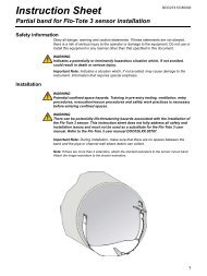
Wall mounting the <strong>950</strong> <strong>Flow</strong> <strong>Meter</strong> requires the optional Wall Mounting Bracket (P/N.<br />
2743). This bracket provides stable, secure mounting for the flow meter and provides<br />
clearance for removing the power supply while the unit is installed. Connect the flow<br />
meter with four ¼-20 screws (provided) using the four threaded inserts on the back of the<br />
case. (See Figure 2).
Figure 2 Wall Mounting Bracket<br />
4.3.2 Suspension Harness Installation (Optional)<br />
Controller Installation<br />
Use the optional Suspension Harness (P/N 2889) to suspend the flow meter in a manhole<br />
or similar site. The suspension harness has two captive ¼-20 S.S. mounting screws<br />
attached to the top of two threaded inserts on the back of the flow meter.<br />
A stainless steel clip is also provided on top of the harness for mounting to an Instrument<br />
Support Bracket (P/N 5713000) or similar support.<br />
When suspending the flow meter, the Suspension Harness utilizes only the top two<br />
threaded mounting inserts, leaving the bottom two free. Do not use the bottom inserts<br />
for suspending any additional equipment. The inserts are designed to support only the<br />
weight of a <strong>950</strong> <strong>Flow</strong> <strong>Meter</strong> and will not adequately support additional weight.<br />
4.3.3 Manhole Rung Hanger (Optional)<br />
The Manhole Rung Hanger (P/N 3533) is a convenient way to hang the <strong>950</strong> <strong>Flow</strong> <strong>Meter</strong><br />
from a manhole ladder rung. Constructed of 304 Stainless Steel, it makes a temporary<br />
mounting as secure as a permanent one.<br />
The Manhole Rung Hanger has two captive thumb screws for securing the bracket to the<br />
top two threaded inserts on the <strong>950</strong> <strong>Flow</strong> <strong>Meter</strong>. The Manhole Rung Hanger also has a<br />
spring loaded handle that secures the Hanger over a rung of up to 1¾ in. (4.4 cm) in<br />
diameter.<br />
When suspending the flow meter, the Manhole Rung Hanger utilizes only the top two<br />
threaded mounting inserts, leaving the bottom two inserts free. Do not use the bottom<br />
inserts for suspending any additional equipment. The inserts are designed to support<br />
only the weight of a <strong>950</strong> <strong>Flow</strong> <strong>Meter</strong> and will not adequately support additional weight.<br />
(See Figure 3 on page 24).<br />
23
Controller Installation<br />
4.4 Installing the Power Supply<br />
24<br />
1<br />
Figure 3 Manhole Rung Hanger<br />
1 Place over ladder rung. 2 Connect bottom inserts to meter.<br />
2<br />
The <strong>950</strong> <strong>Flow</strong> <strong>Meter</strong> is designed to accept either the manufacturer’s 12 VDC battery pack<br />
or ac power converter.<br />
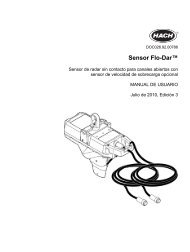
1. Place the power supply on the back of the flow meter. (See Figure 4).<br />
2. Pull the two rubber hold-down clamps up and over the clips on each end of the power<br />
supply.<br />
3. Connect the power supply connector to the port labeled 12 VDC on the top left side<br />
of the case.<br />
Figure 4 Power Supply and Interface Connectors<br />
1<br />
2<br />
1 Power Supply 3 12 VDC Port 5 Sampler Port<br />
2 Rubber Hold-down Clamp 4 RS232 Port<br />
12 VDC<br />
RS232<br />
Sampler<br />
3<br />
4<br />
5
4.5 Interface Connector Descriptions<br />
4.6 12 VDC Connections<br />
Controller Installation<br />
Note: All interface receptacles are covered with push-on caps. These caps are designed to protect<br />
the connector pins from dirt and moisture and should be attached to any receptacle not in use.<br />
The interface connector ports are located on the left side of the flow meter case. The <strong>950</strong><br />
<strong>Flow</strong> <strong>Meter</strong> comes standard with three interface ports.<br />
• 12 VDC (Power Input)<br />
• RS232 (Serial Communications Port)—(See section 8.1 on page 61 for connection<br />
and programming details).<br />
• Sampler (Automatic Liquid Sampler Control)<br />
In addition, the flow meter can be connected to a wide variety of optional peripheral<br />
devices:<br />
• Rain Gauge (section 7.1 on page 53) • Modem (section 8.2.1 on page 63)<br />
• pH (section 7.2 on page 54) • Analog Inputs (section 8.3.2 on page 70)<br />
• ORP (section 7.3 on page 55) • Alarm Relays (section 8.4.1 on page 72)<br />
• Dissolved Oxygen (section 7.4 on page 56) • 4–20 mA Current Loop(section 8.3.1 on page 68)<br />
• Conductivity (section 7.5 on page 58)<br />
One or a combination of up to three sensors can be connected to the <strong>950</strong> <strong>Flow</strong> <strong>Meter</strong>,<br />
depending on the system configuration.<br />
• Downlook Ultrasonic Depth Sensor (section 6.1 on page 37)<br />
• In-Pipe Zero Deadband Ultrasonic Depth Sensor (section 6.2<br />
on page 40)<br />
• Submerged Area/Velocity Sensor (section 6.3 on page 42)<br />
• Low Profile Velocity Only Sensor (section 6.4 on page 45)<br />
• Submerged Depth Only Sensor (section 6.5 on page 46)<br />
• Bubbler Depth or Bubbler Area/Velocity Sensor (section 6.6<br />
on page 48)<br />
This connection supplies power to the flow meter. Power sources include a battery<br />
(Ni-Cad or Lead Acid), an ac power pack, or an external source such as a deep-cycle<br />
marine battery or vehicle cigarette lighter connection. Refer to Batteries and Chargers on<br />
page 133 for more information.<br />
Although the <strong>950</strong> <strong>Flow</strong> <strong>Meter</strong> will operate on any attached 12 VDC power supply, the<br />
instrument will assume it is battery operated if it detects a less than 14.2 VDC input and<br />
will assume it is operating on an ac power converter if it detects a greater than 14.2 VDC<br />
input.<br />
Table 2 12 VDC Connector Pin Assignments<br />
Pin Signal Description<br />
A Ground<br />
B 12 to 17 VDC, unregulated<br />
25
Controller Installation<br />
4.7 Sampler<br />
4.7.1 Sampler Connections<br />
4.7.2 Sampler Programming<br />
26<br />
The sampler interface receptacle is used to connect a wastewater sampler to the <strong>950</strong><br />
<strong>Flow</strong> <strong>Meter</strong>.<br />
Table 3 Sampler Connector Pin Assignments<br />
Pin Signal Description Wire Color Purpose Rating<br />
A 12 VDC (input only) orange Pin A may receive power from an external device, 500 mA<br />
max load.<br />
B ground brown Pin B provides the ground line that is used in conjunction with<br />
the other signals on the connector.<br />
C flow pulse output yellow<br />
D sampler start black<br />
E event input red<br />
F bottle number input green<br />
Used in with Pin B to signal a sampler that a pre-determined<br />
amount of flow has accumulated with a 500 ms pulse.<br />
Used to “wake up” a waste water sampler when a set point<br />
condition is met so that it can begin its sampling program.<br />
Configure the flow meter for this pin in<br />
Set Point Sampling on page 105.<br />
Used in conjunction with Pin B, this line is normally allowed to<br />
float and is switched to ground (by transistor) for the entire<br />
period that the set point condition exists.<br />
Received from a waste water sampler and indicates that a<br />
sample has been collected. “Sample Taken” information will<br />
appear in the data printout when downloaded.<br />
Received from a waste water sampler and used in conjunction<br />
with the Event Input signal. It tells the flow meter which bottle<br />
was used when a sample was taken. “Sample Times and<br />
Dates” information will appear in the data printout when<br />
downloaded.<br />
12 VDC (w/battery)<br />
to 17 VDC pulse<br />
(w/ac power pack)<br />
500 mA max.<br />
12 VDC (w/battery)<br />
to 17 VDC pulse<br />
(w/ac power pack)<br />
24 VDC (max) at<br />
100 mA (max)<br />
Cable Required for Sampler Connections<br />
• Multi-Purpose Half Cable Assembly, 3.0 m (10 ft), 6-pin connector on one end, tinned<br />
wire leads on the other end (P/N 941) or<br />
• Multi-Purpose Full Cable Assembly, 3.0 m (10 ft), 6-pin connector on both ends (P/N<br />
940).<br />
• Cables with 7.6 m (25 ft) lengths and custom sizes are also available.<br />
1. From the Main Menu, select SETUP>MODIFY SELECTED ITEMS.<br />
2. Scroll down and highlight SAMPLER PACING using the up and down arrow soft keys.<br />
Press SELECT to continue.<br />
3. Enable Sampler pacing using the CHANGE CHOICE soft key. Press ACCEPT to<br />
continue.<br />
4. Set the Sampler Pacing using the numeric keypad and Change Units using the<br />
CHANGE UNITS soft key. The <strong>950</strong> <strong>Flow</strong> <strong>Meter</strong> will output one<br />
12 VDC pulse each time the specified amount of flow has occurred.<br />
5. Press ACCEPT.<br />
N/A<br />
N/A
Controller Installation<br />
4.8 Installation Requirements for CE Marked <strong>950</strong> <strong>Flow</strong> <strong>Meter</strong> Models<br />
<strong>Sigma</strong> <strong>950</strong> <strong>Flow</strong> <strong>Meter</strong>s bearing a CE mark have special use and installation<br />
requirements that are subject to the European Union’s Notified Body use limitations as<br />
indicated below.<br />
Only the <strong>950</strong> flow meter models, part numbers and options listed below are approved for<br />
use in the EU under <strong>Hach</strong>’s CE marking scope:<br />
Description<br />
Catalog<br />
Number<br />
<strong>950</strong> Combination <strong>Flow</strong> <strong>Meter</strong> with both AV + Bubbler Sensors 3248<br />
<strong>950</strong> <strong>Flow</strong> <strong>Meter</strong> with AV Sensors only 3522<br />
<strong>950</strong> <strong>Flow</strong> <strong>Meter</strong> with Bubbler Sensors only 2672<br />
AV Sensor Options (xx-xxx = depth range, fill option and cable length) 770xx-xxx<br />
Bubbler Sensor Options (xxx = cable lengths) 88007-xxx<br />
pH Sensors with 7.6 m / 25 ft cable length 3328<br />
pH Sensors with 15.2 m / 50 ft cable length 5172<br />
4-20mA output option 2684<br />
12VDC Battery Option 1414<br />
230V 50Hz Battery Eliminator with Continental EU plug 5721400<br />
230V 50Hz Battery Eliminator with UK plug 6244500<br />
230V 50Hz Battery Eliminator with Italian plug 6244600<br />
The use and location restrictions below apply:<br />
• The <strong>Sigma</strong> <strong>950</strong> <strong>Flow</strong> <strong>Meter</strong> is approved for use in the EU only when placed<br />
underground in sewers, drain pipes and similar underground locations.<br />
• The <strong>950</strong> <strong>Flow</strong> <strong>Meter</strong> shall be connected only to an AC Mains source that is dedicated<br />
to underground service. The mains service must not feed any residential locations.<br />
If the <strong>950</strong> <strong>Flow</strong> <strong>Meter</strong> is operated in areas where high levels of RF energy or severe<br />
electrical transients are present, performance-related problems can result from<br />
electromagnetic interference. These conditions are not expected to be present in the<br />
types of underground locations indicated above for the <strong>950</strong> <strong>Flow</strong> <strong>Meter</strong> use model.<br />
27
Controller Installation<br />
28
Section 5 Basic Programming Setup<br />
5.1 Initial Power-Up of <strong>Meter</strong><br />
5.2 Basic Programming<br />
Step 1 - Setup<br />
After power is applied, the flow meter performs a complete diagnostic self-test and<br />
displays the menu shown when the unit was last turned off. The Main Menu is the starting<br />
point for all programming operations. The Main Menu offers four choices:<br />
• Setup—Basic programming<br />
• Status—Lists all currently measured readings<br />
• Display Data—Shows graphs and tables of logged data<br />
(See Displaying Data on page 95)<br />
• Options—Advanced programming<br />
Regardless of the current menu displayed, pressing the Main Menu function key will bring<br />
up the Main Menu screen.<br />
Setup and Option functions lead to sub-menus which configure the basic and advanced<br />
features of the flow meter. Refer to the <strong>950</strong> <strong>Flow</strong> <strong>Meter</strong> Basic Programming Setup on<br />
page 87. The Display Data and Status lead to sub-menus which provide information only.<br />
Press the STATUS soft key to display any data channels that have enabled logging (flow,<br />
pH, temp., etc.).<br />
11:00 AM 21 - APR - 01 * Main Menu*<br />
DISPLAY DATA SETUP<br />
OPTIONS STATUS<br />
READY TO START<br />
Note: To make changes to the program entries after the basic programming setup, press the<br />
MAIN MENU key and select SETUP>MODIFY SELECTED ITEMS. Highlight the program<br />
entry using the up and down arrow soft keys.<br />
Basic programming setup must be performed, in its entirety, after the instrument is<br />
installed. Refer to the <strong>950</strong> <strong>Flow</strong> <strong>Meter</strong> Basic Programming Setup on page 87 for more<br />
information.<br />
The basic program setup will modify all items: flow units, primary devices, program lock,<br />
sampler pacing, site ID, velocity direction, velocity units, velocity cutoff/velocity default.<br />
Note: Velocity features will only display when using a <strong>950</strong> area/velocity flow meter.<br />
1-A. Press SETUP from the Main Menu to prepare the <strong>950</strong> <strong>Flow</strong> <strong>Meter</strong><br />
for use.<br />
1-B. Press MODIFY ALL ITEMS and press ACCEPT to begin setting up the flow units.<br />
Step 2 - <strong>Flow</strong> Units<br />
Note: Different flow units can be selected in the Sampler Pacing programming section (see Sampler<br />
Pacing on page 32).<br />
2-A. From the Modify All Items screen, highlight <strong>Flow</strong> Units using the UP and DOWN<br />
keys. Press the SELECT soft key to continue.<br />
29
Basic Programming Setup<br />
Step 3 - Level Units<br />
30<br />
11:00 AM 21 - APR - 01 * Main Menu*<br />
LOGIN<br />
REVIEW ALL<br />
ITEMS<br />
READY TO START<br />
2-B. Press CHANGE CHOICE to cycle through the flow unit choices. Refer to Table 4 for<br />
flow unit choices. The flow unit will be used whenever a flow reading is displayed or<br />
logged.<br />
2-C. When the desired choice is displayed press ACCEPT to continue and set level units.<br />
3-A. Next the flow meter will display the Level Units screen.<br />
MODIFY<br />
ALL ITEMS<br />
MODIFY<br />
SELECTED<br />
ITEMS<br />
11:00 AM 21 - APR - 01 FLOW UNITS<br />
CHANGE<br />
ACCEPT<br />
CHOICE<br />
FLOW UNITS<br />
mdg CANCEL<br />
SELECT APPROPRIATE UNITS<br />
Table 4 <strong>Flow</strong> Unit Choices<br />
Abbreviation <strong>Flow</strong> Unit Abbreviation <strong>Flow</strong> Units<br />
gps Gallons per second cfs Cubic feet per second<br />
gpm Gallons per minute cfm Cubic feet per minute<br />
gph Gallons per hour cfh Cubic feet per hour<br />
lps Liters per second cfd Cubic feet per day<br />
lpm Liters per minute cms Cubic meters per second<br />
lph Liters per hour cmm Cubic meters per minute<br />
mgd Million gallons per day cmh Cubic meters per hour<br />
afd Acre-feet per day cmd Cubic meters per day<br />
3-B. Select the units of measure to use when displaying level readings (Table 5). Level<br />
units of measure are used whenever a level reading is displayed or logged.<br />
Table 5 Level Units Choices<br />
Abbreviation Level Unit<br />
in. inches<br />
ft feet<br />
cm centimeters<br />
M meters
Basic Programming Setup<br />
3-C. Press CHANGE CHOICE to cycle through each of the level unit choices. Press<br />
ACCEPT to continue to primary device setup.<br />
Step 4 - Primary Device<br />
Note: Selecting the appropriate primary device is critical for proper flow rate calculations.<br />
Primary Device Description<br />
4-A. Next, the flow meter will display the Primary Device screen.<br />
4-B. Select the desired primary device, enter the calculation method, shape, and pipe<br />
diameter for that primary device.<br />
4-C. Press CHANGE CHOICE to cycle through the primary device choices (see Table 6,<br />
Table 7, Table 8, and Table 9). Show the size and details required for each. Press<br />
ACCEPT to continue to Program Lock.<br />
11:00 AM 21 - APR - 01 PRIMARY DEVICE<br />
ACCEPT<br />
PRIMARY DEVICE:<br />
WEIR<br />
SELECT PRIMARY DEVICE<br />
Table 6 Primary Device Choices<br />
None—Level Only No primary device installed. Level measurement only.<br />
CHANGE<br />
CHOICE<br />
Weir<br />
Compound, Cipolletti, Contracted rectangular, Non-contracted rectangular, ThelMar, V-Notch (22.5-120°),<br />
Compound V-Notch (See Table 7)<br />
Flume Parshall, Trapezoidal, H-type, HL-type, HS-type, Leopold-Lagco, Palmer Bowlus (See Table 8)<br />
Nozzle California pipe<br />
Power Equation<br />
Head vs. <strong>Flow</strong><br />
Manning Equation<br />
Area Velocity<br />
Enter variables K1 , K2 , n1 and n2 Q K<br />
K1 (0–9999.99), K2 (+/- 0–9999.99), n<br />
1<br />
H<br />
1 and n2 (1–9.99)<br />
n1 K<br />
2<br />
Hn2 =<br />
+<br />
Two independent user–entered look up tables of up to 99 points each<br />
Enter up to two tables of up to 100 user-defined head vs. flow points.<br />
Head: 0–99.99 in feet or centimeters <strong>Flow</strong>: 0–99999.99 in any desired units<br />
Rectangular channel, U-shaped, trapezoidal channel or Circular pipe<br />
Enter pipe diameter, slope & roughness coefficient. Pipe dia.: 4–240 in. or 101–6096 cm<br />
Percent Slope: 0.001–1.00 [1 unit per hundred units = 0.01 slope] Example: 1 m of decline every 100 m =<br />
0.01 slope.<br />
Manning Roughness<br />
Circular Pipe: Enter pipe dia., 4–240 in.(10–610 cm)<br />
Rectangular Channel: Enter width, 4–999.99 in. (10– 2540 cm)<br />
Trapezoidal Channel: Enter width of channel bottom, width of channel top and channel depth, range for<br />
all: 4–999.99 in. (10– 2540 cm)<br />
U-Shaped Channel: Enter channel width, 4–999.99 in. (10–2540 cm)<br />
Weir Description<br />
Table 7 Weir Choices<br />
Cipolletti Crest width is in. or cm (1–960 in. or 2.54–2438 cm)<br />
Contracted Rectangular Crest width is in. or cm (1–960 in. or 2.54–2438 cm)<br />
31
Basic Programming Setup<br />
Weir Description<br />
Non-Contracted Rectangular Crest Width is in. or cm (1–960 in. or 2.54–2438 cm)<br />
ThelMar Size in inches. (6, 8, 10, 12 or 15 in.)<br />
V-Notch Angle of notch in degrees (22.5 to 120°)<br />
Compound V-Notch<br />
Flumes Description<br />
Step 5 - Program Lock<br />
Program Lock provides a protective passcode to keep unauthorized personnel from<br />
tampering with the keyboard and/or prevent access via RS232 or modem. When enabled,<br />
a screen will require a password to be entered. The Program Lock password factory is<br />
set as <strong>950</strong>0 and cannot be changed.<br />
Step 6 - Sampler Pacing<br />
32<br />
Angle of notch in degrees (22.5–120°), notch depth in inches, rectangular width in inches<br />
(0–120 in. or 0–304 cm), Contracted or non-contracted.<br />
Table 8 Flume Choices<br />
Parshall Flume size in inches (1, 2, 3, 6, 9, 12, 18, 24, 30, 36, 48, 60, 72, 84, 96, 108, 120 or 144 in.)<br />
Trapezoidal Flume size (60° S, 60° L, 60° XL, 45° 2", 45° 12")<br />
H - Type Flume size in feet (0.5, 0.75, 1.0, 1.5, 2.0, 2.5, 3.0 or 4.5 ft)<br />
HL - Type Flume size in feet 3.5’, 4.0'<br />
HS -Type Flume size in feet (0.4, 0.6, 0.8 or 1.0 ft)<br />
Leopold-Lagco Flume size in inches (4, 6, 8, 10, 12, 15, 18, 20, 21, 24, 27, 30, 36, 42, 48, 54, 60, 66 or 72 in.)<br />
Palmer-Bowlus Flume size in inches (4, 6, 8, 10, 12, 15, 18, 21, 24, 27, 30, 36, 42, 48, 60 or 72 in.)<br />
Device or Equation Description<br />
Level vs. Area Table<br />
(two level vs. area<br />
tables are provided)<br />
Nozzle Enter nozzle diameter<br />
Table 7 Weir Choices (continued)<br />
Table 9 Other Primary Devices<br />
Enter up to two tables of up to 99 user-defined level vs. area points; Level: 0–999.9 in ft, in., m or cm<br />
Area: 1–99999.99 in ft 2 , in. 2 , m 2 or cm 2<br />
5-A. Next, the flow meter will display the Program Lock screen.<br />
5-B. Enable or Disable the program lock using the CHANGE CHOICE soft key. Press<br />
ACCEPT to continue to Sampler Pacing.<br />
6-A. Next, the flow meter will display the Sampler Pacing screen.<br />
6-B. Enable Sampler Pacing using the CHANGE CHOICE soft key. Refer to Table 10 for<br />
flow unit choices for sampler pacing.
6-C. Press ACCEPT to continue with Site ID.<br />
Basic Programming Setup<br />
Step 7 - Site ID Note: A text Site ID may be programmed via <strong>Hach</strong>'s management software and an RS232<br />
connection.<br />
Step 8 - Total <strong>Flow</strong> Units<br />
11:00 AM 21 - APR - 01 SAMPLER PACING<br />
ACCEPT<br />
CLEAR<br />
ENTRY<br />
SAMPLER PACING<br />
500 gal<br />
(USE NUMERIC KEYPAD)<br />
Creates an 1–8 digit site identification number. The site ID will appear on all data printouts.<br />
This feature is useful when multiple sites are monitored using a single flow meter or if data<br />
readings from multiple flow meters are collected.<br />
7-A. Next, the flow meter will display the Site ID screen.<br />
7-B. Enter the site ID using the numeric keypad.<br />
7-C. Press ACCEPT to continue to total flow units.<br />
Table 10 <strong>Flow</strong> Unit Choices<br />
Abbreviation Volume<br />
8-A. Next, the flow meter will display the Total <strong>Flow</strong> Units screen.<br />
8-B. Set the Total <strong>Flow</strong> Units (gal, ltr, m 3 , af, cf) using the CHANGE CHOICE soft key. Total<br />
flow units of measure are used whenever a total flow unit is displayed or logged.<br />
8-C. Press ACCEPT to continue to velocity direction.<br />
gal gallons<br />
ltr liters<br />
m3 cubic meters<br />
af acre-feet<br />
cf cubic-feet<br />
Step 9 - Velocity Direction (only when logging velocity)<br />
9-A. Next, the flow meter will display the Velocity Direction screen.<br />
9-B. Set the Velocity Direction using the CHANGE CHOICE soft key.<br />
The Velocity Direction feature adapts to a number of difficult sites that would otherwise<br />
not be able to measure velocity properly (Upstream, Downstream, and Always Positive).<br />
For more information see the Velocity-Only Sensor Instruction Sheet (Cat. No. 88006-89).<br />
9-C. Press ACCEPT to move to velocity units setup.<br />
9-D. Set the velocity units (ft/s, mS) using the CHANGE CHOICE soft key.<br />
CHANGE<br />
UNITS<br />
CANCEL<br />
33
Basic Programming Setup<br />
34<br />
9-E. Read the Velocity cutoff warning on the screen. Press any key to continue.<br />
9-F. Enter the Velocity Cutoff, using the numeric keypad. Press ACCEPT<br />
to continue.<br />
9-G. Enter the Velocity Default using the numeric keypad. Press ACCEPT to end the<br />
basic programming setup.<br />
Note: Velocity Cutoffs are used at sites where low velocities and frequent low particulate<br />
concentrations occur, if velocity cannot be measured.<br />
Example 1:<br />
Velocity Cutoff = 0.20 ft/s, Velocity Default = 0 ft/s<br />
If the velocity falls below 0.20 ft/s, the meter will store a value of 0 ft/s until the velocity<br />
increases above 0.20 ft/s.<br />
Example 2:<br />
Velocity Cutoff = 0.20 ft/s, Velocity Default = 0.20 ft/s<br />
If the velocity falls below 0.20 ft/s, the meter will store a value of 0.20 ft/s until the<br />
velocity increases above 0.20 ft/s.<br />
5.3 Starting and Stopping Programs<br />
Note: When selecting START FROM BEGINNING, all logged data will be cleared from memory.<br />
When saving the logged data, make sure the data is downloaded to a DTU or personal computer. If<br />
a program is complete, the logger can only be restarted from the beginning (and will clear all logged<br />
data).<br />
When basic programming setup is completed, “run” (or execute) the program selections.<br />
Press the RUN/STOP key to run a program, resume a currently halted program, or stop a<br />
program.<br />
If a program has been halted (and no changes to the program settings were made while it<br />
was stopped), press the RUN key. Select either resume to previously running program<br />
(and retain all logged data) or Start From Beginning (and clear all logged data).
Status Description<br />
Program is Running<br />
Program is Halted<br />
Data Logging, 4-20 mA outputs, sampler control and alarm checking are active.<br />
Basic Programming Setup<br />
Logging stops until the program is restarted. It continues with the last logged value when restarted.<br />
4–20 mA outputs remain unchanged<br />
Sampler control is disabled<br />
Alarm checking is disabled<br />
Program is Complete or Ready to Start<br />
Program Complete<br />
No data logging<br />
4–20 mA outputs stay at last value<br />
No sampler interface<br />
No alarm checking<br />
A logger is off or lost power for longer than 3 hours or datalogging memory is full (see Data Log on page 99).<br />
35
Basic Programming Setup<br />
36
Section 6 Sensor Installation<br />
An individual <strong>Sigma</strong> <strong>950</strong> flow meter may have one or more of the following sensors:<br />
• Downlooking Ultrasonic Sensor • Submerged Pressure<br />
Area/Velocity Sensor<br />
• In-Pipe Ultrasonic Sensor • Velocity-Only (Low Profile)<br />
Sensor<br />
• AV Bubbler<br />
6.1 Downlooking Ultrasonic Depth Sensor<br />
6.1.1 Downlooking Ultrasonic Depth Sensor Connection<br />
Note: Use a bare leads sensor<br />
and junction box (P/N 3658) for conduit installation.<br />
The <strong>Sigma</strong> <strong>950</strong> <strong>Flow</strong> <strong>Meter</strong> uses a 50 kHz or 75 kHz Downlooking Ultrasonic Depth<br />
Sensor. The ultrasonic sensor receptacle is on the left side of the flow meter and labeled<br />
Ultrasonic. The connector is keyed and can only be inserted key up.<br />
Note: Cutting or splicing the sensor cable may cause instrument malfunction and void the warranty.<br />
Remote Ultrasonic Connection<br />
A Remote Ultrasonic factory-installed Option is available (P/N 3170) which allows for the<br />
extension of the ultrasonic sensor cable (see Figure 5).<br />
6.1.2 Downlooking Ultrasonic Depth Sensor Programming<br />
• Submerged Pressure Sensor<br />
• Bubbler<br />
Table 11 Downlooking Ultrasonic Depth Sensor Connector Pin Assignments<br />
Pin Signal Description Wire Color<br />
A temperature (+) red<br />
B temperature (-) black<br />
C ultrasonic (+) shield<br />
D ultrasonic (-) clear<br />
The downlooking ultrasonic depth sensor does not require specific programming, unless<br />
more than one sensor option is connected to the meter. When more than one sensor<br />
option is connected:<br />
1. From the Main Menu, select OPTIONS>LEVEL SENSOR.<br />
Select Ultra-Sonic using the CHANGE CHOICE soft key, then press the ACCEPT soft key.<br />
37
Sensor Installation<br />
38<br />
Figure 5 Remote Ultrasonic Sensor Option<br />
6.1.3 Downlooking Ultrasonic Depth Sensor Calibration<br />
6.1.3.1 Liquid Depth<br />
J2<br />
J3<br />
Clear<br />
Shield<br />
RED<br />
BLK<br />
5<br />
6<br />
GRN<br />
BLK<br />
RED<br />
WHT<br />
1 Enclosure 13.97 x 22.86 x 4.0 cm (5.5 x 9.0 x 4.0 in.) 3 To flow meter 5 Cable (P/N 2716)<br />
2 Customer-supplied conduit to <strong>950</strong> flow meter. 4 Cable (P/N SE 818) 6 Ultrasonic Transducer<br />
Calibrate the current water depth via one of two methods; Liquid Depth or Sensor Height.<br />
An Invisible Range can also be set which allows the transducer to ignore reflections from<br />
obstructions between the sensor and the water surface, such as ladder rungs, channel<br />
side walls, etc. Each method has its own advantages and disadvantages; selecting the<br />
proper method will depend upon the site conditions. Calibrate the ultrasonic sensor each<br />
time the sensor is installed at a new site.<br />
This method requires the depth of liquid in the channel that is contributing to flow. In a<br />
round pipe, the entire depth typically contributes to flow. In a weir, only the depth that is<br />
flowing over the weir plate contributes to flow. Many flumes have specific requirements,<br />
refer to Working with Primary Devices on page 105. Depth calibration is primarily used<br />
when:<br />
Access is available to the primary device for a physical measurement of the liquid depth,<br />
and when water is flowing during installation of the <strong>950</strong> <strong>Flow</strong> <strong>Meter</strong> (channel is not dry).<br />
Note: Always re-check the Level Adjust when re-installing the flow meter.<br />
1. From the Main Menu, select OPTIONS>ADVANCED OPTIONS><br />
CALIBRATION>ULTRASONIC SENSOR.<br />
J5<br />
J4<br />
2. Select Calibrate U-Sonic using the UP and DOWN soft keys. Press SELECT.<br />
2<br />
1<br />
4<br />
3
6.1.3.2 Sensor Height<br />
6.1.3.3 Setting the Invisible Range<br />
Sensor Installation<br />
3. Select Standard as the type of Ultrasonic Transducer using the CHANGE CHOICE soft<br />
key. Press ACCEPT to continue.<br />
Temperature Time Constant<br />
The speed of sound in air varies with the temperature of the air. The ultrasonic sensor is<br />
equipped with temperature compensation to help eliminate the effect of temperature<br />
variation under normal site conditions. The transducer must be equal to the ambient air<br />
temperature at the site prior to calibration for optimum results. The manufacturer also<br />
recommends that sensors be shielded from direct sunlight for this reason.<br />
4. Enter the ambient air temperature at the transducer location. For optimum results,<br />
allow enough time (100 minutes) to ensure that the sensor is at equilibrium with the<br />
surrounding ambient temperature. Press ACCEPT to continue.<br />
5. Select the Liquid Depth method and enter the new level.<br />
6. Take a physical measurement of the liquid depth and enter the value.<br />
7. Press ACCEPT when finished.<br />
This method requires you to enter the distance between the face of the ultrasonic sensor<br />
and the zero flow point in the primary device. The zero flow point in a primary device is<br />
the level at which flow ceases. In a round pipe the zero flow point would typically be the<br />
invert or bottom of the pipe. In a V-notch weir the zero flow point occurs when the liquid<br />
behind the weir is level with the bottom of the ‘V’. (There would still be liquid behind the<br />
weir plate but it would not be contributing to flow). Sensor Height calibration is generally<br />
used when access to the primary device is difficult (such as confined space entry in a<br />
manhole) or there is no liquid flowing during installation of the flow meter.<br />
1. From the Main Menu, select OPTIONS>ADVANCED<br />
OPTIONS>CALIBRATION>ULTRASONIC SENSOR.<br />
2. Select Calibrate U-Sonic using the UP and DOWN soft keys. Press SELECT.<br />
3. Select Standard as the type of Ultrasonic Transducer using the CHANGE CHOICE soft<br />
key. Press ACCEPT to continue.<br />
4. Enter the ambient air temperature at the transducer location. For optimum results,<br />
allow enough time (100 minutes) to ensure that the sensor is at equilibrium with the<br />
surrounding ambient temperature. Press ACCEPT<br />
to continue.<br />
5. Select the Sensor Height method and enter the new level.<br />
6. Enter the distance from the face of the transducer to the zero flow point of the<br />
primary device.<br />
7. Press ACCEPT when finished.<br />
1. From the Main Menu, select OPTIONS>ADVANCED<br />
OPTIONS>CALIBRATION>ULTRASONIC SENSOR.<br />
2. Select the Invisible Range option using the UP and DOWN soft keys. Press SELECT to<br />
continue.<br />
3. Enter the Distance to End of the Invisible Range using the keypad.<br />
4. Select either inches or centimeters using the CHANGE UNITS soft key. The distance<br />
must be greater than the minimum deadband of 23 cm (9 in.) for the 75 kHz sensor<br />
and 38.1 cm (15 in.) for the 50 kHz sensor.<br />
5. Press ACCEPT when finished.<br />
39
Sensor Installation<br />
6.2 In-Pipe Zero Deadband Ultrasonic Depth Sensor<br />
40<br />
The in-pipe zero deadband ultrasonic depth sensor is used in pipes where depth<br />
measurement near the top of the pipe is desired. The sensor will read the depth until<br />
liquid reaches from the bottom of the sensor housing.<br />
6.2.1 In-Pipe Zero Deadband Ultrasonic Depth Sensor Connection<br />
6.2.2 Programming the In-Pipe Zero Deadband Ultrasonic Depth Sensor<br />
6.2.3 Beam Angle<br />
Table 12 In-Pipe Zero Deadband Ultrasonic Depth Sensor Connector<br />
Pin Assignments<br />
Pin Signal Description Wire Color<br />
A temperature (+) red<br />
B temperature (-) black<br />
C ultrasonic (+) shield<br />
D ultrasonic (-) clear<br />
The in-pipe zero deadband ultrasonic depth sensor does not require operator<br />
programming, unless more than one sensor option is connected to the <strong>950</strong> <strong>Flow</strong> <strong>Meter</strong>.<br />
When more than one sensor option is connected:<br />
1. From the Main Menu, select OPTIONS > LEVEL SENSOR<br />
2. Select Ultra-Sonic Sensor using the CHANGE CHOICE soft key, then<br />
press ACCEPT.<br />
The narrow beam of sound that emanates from the bottom of the in-pipe ultrasonic<br />
sensor spreads out at an angle of ±12° (-10 dB) as it travels away from the sensor. This<br />
means that if the sensor is mounted too high above a narrow channel, the beam may be<br />
too wide when it reaches the bottom of the channel. This may cause false echoes from<br />
the sides of the channel walls.<br />
6.2.4 Calibrating the In-Pipe Zero Deadband Ultrasonic Depth Sensor<br />
Calibrate the in-pipe sensor each time the sensor is installed at a new site. Calibrate the<br />
in-pipe via one of two methods; Liquid Depth or Sensor Height. Each method has its own<br />
advantages and disadvantages. Liquid Depth calibration is the recommended calibration<br />
method. Use the sensor height method only when Liquid Depth calibration is not an<br />
option. An Invisible Range can also be set which allows the transducer to ignore<br />
reflections from obstructions between the sensor and the water surface, such as ladder<br />
rungs, channel side walls, etc.<br />
1. From the Main Menu, select OPTIONS > ADVANCED OPTIONS.<br />
2. Highlight Calibration, using the UP and DOWN soft keys. Press SELECT.<br />
3. Highlight Ultra-Sonic Sensor, using the UP and DOWN soft keys. Press SELECT to<br />
continue.<br />
4. Highlight Calibrate U-Sonic Sensor and press SELECT.<br />
5. Select the type of ultrasonic transducer (In-Pipe), using the CHANGE CHOICE soft<br />
key.<br />
6. Press ACCEPT to continue.
Sensor Installation<br />
7. Enter the ambient air temperature at the transducer location. For optimum results,<br />
allow enough time (100 minutes) to ensure that the sensor is at equilibrium with the<br />
surrounding ambient temperature.<br />
The speed of sound in air varies with the temperature of the air. The ultrasonic sensor is<br />
equipped with temperature compensation to help eliminate the effect of temperature<br />
variation under normal site conditions.<br />
8. Press ACCEPT to continue.<br />
Liquid Depth<br />
Liquid depth requires knowing the level or depth of the liquid in the channel that is<br />
contributing to flow. Liquid depth calibration is the recommended calibration method for<br />
the in-pipe ultrasonic sensor.<br />
Continue from Step 8, above:<br />
1. Select the Liquid Depth method.<br />
2. Take a physical measurement of the liquid depth (head) and enter the value.<br />
3. Press ACCEPT when finished.<br />
Sensor Height<br />
Sensor height calibration is generally used when access to the primary device is difficult<br />
(such as confined space entry in a manhole) or when there is no liquid flowing during<br />
installation of the flow meter. This calibration method requires compensation for the<br />
internal deadband in the sensor housing. Measurement uncertainty increases to 1.07 cm<br />
(0.035 ft) for a ±30 cm (±1 ft) change in level from the calibration point.<br />
Use this method only if the Liquid Depth method is not an option.<br />
Continue from Step 8, above:<br />
1. Measure the distance from the bottom of the sensor to the zero flow point. Add 18 cm<br />
(7.09 in.) to the measured distance to obtain the total zero flow distance for the<br />
in-pipe sensor. Refer to Figure 6 on page 42.<br />
2. Select the Sensor Height calibration method and enter the total zero flow distance<br />
from Step 1.<br />
3. Press ACCEPT when finished.<br />
Setting the Invisible Range<br />
Note: When programming the invisible range, 18 cm (7.09 in.) must be added to the desired range<br />
to compensate for the internal deadband distance between the sensor, the reflector, and the bottom<br />
of the sensor housing.<br />
The <strong>950</strong> <strong>Flow</strong> <strong>Meter</strong> is equipped with an invisible range feature to prevent false echoes<br />
from tops of channel walls, ladder rungs, shelves, etc. A user-selected range is defined<br />
that is invisible to the flow meter. Do not extend the invisible range to where it meets or<br />
overlaps the highest expected level in the channel. Have a gap of at least 5 cm (2 in.)<br />
between the invisible range and the highest expected level. Only objects beyond the<br />
invisible range can be detected.<br />
41
Sensor Installation<br />
42<br />
Figure 6 Side View of In-Pipe<br />
1 Pipe Ceiling 5 Internal Deadband (18 cm (7.09 in.))<br />
2 Distance from Sensor (Range: 0 to 2.4 m (0 to 8 ft)) 6 Pipe Floor<br />
3 45° Deflector 7 Minimum distance to reflecting obstruction (2 m<br />
(82 in.))<br />
4 Ultrasonic Sensor 8 Reflecting Obstruction<br />
1. From the Main Menu, select OPTIONS>ADVANCED OPTIONS> CALIBRATION><br />
ULTRASONIC SENSOR.<br />
2. Select the Invisible Range option using the UP and DOWN soft keys. Press SELECT to<br />
continue.<br />
3. Enter the Distance to End of the Invisible Range using the keypad.<br />
4. Select either inches or centimeters using the CHANGE UNITS soft key. Press ACCEPT<br />
when finished.<br />
6.3 Submerged Area/Velocity Sensor<br />
6.3.1 Bare Lead Sensor Cables<br />
Submerged Area/Velocity sensors can measure depth and velocity simultaneously.<br />
Bare lead sensor cables are used in those cases where the cable will be run through a<br />
conduit. When conduit is used, it is recommended that the conduit be 1-inch or larger.<br />
6.3.2 Junction Box Connection Procedure<br />
Connect the bare leads to the flow meter using a junction box (P/N 4730). This junction<br />
box is a physical connection point for the sensor wires and breather tubing.<br />
Refer to Figure 7 for the following procedure.<br />
1. Remove the four cover screws, cover, and cover gasket from the junction box.<br />
Unscrew the cable-clamp hex nut on the box enough to allow insertion of the sensor<br />
cable.
Sensor Installation<br />
2. Insert the sensor cable into the box and make connections. Refer to the wiring<br />
diagram on the inside cover of the box, connect each wire to its corresponding<br />
terminal screw, observing the wire colors listed in that diagram. See Table 13.<br />
3. Connect the tubing in the cable to the clear tubing in the box that is already<br />
connected to the exit fitting.<br />
4. Slip the cable in or out of the box sufficiently to create a slight loop in the wires and<br />
tubing to allow strain relief and then tighten the cable-clamp hex nut.<br />
5. Being careful to align the cover gasket (P/N 2101), reattach the cover and gasket to<br />
the box with the screws.<br />
6. Connect clear tubing between the top tubing nipple on the desiccant canister and the<br />
brass tubing nipple on the junction box.<br />
7. Connect the short, connector-terminated cable to the “velocity” connector on the flow<br />
meter.<br />
Figure 7 Junction Box Probe and Cable Connection<br />
1<br />
7<br />
6<br />
5<br />
1 Connect to meter 4 Gasket (P/N 2101) 7 Connect sensor cable wires<br />
2 Connect to desiccant tubing 5 Insert tubing (P/N 4628)<br />
3 Cover 6 Connect to sensor cable<br />
Table 13 Submerged Area/Velocity Sensor Connection Pin Assignments<br />
Pin Signal Description Wire Color<br />
A +12 VDC red<br />
B ground green<br />
C receive (ground) b/w shield<br />
4<br />
3<br />
2<br />
43
Sensor Installation<br />
6.3.3 Submerged Area/Velocity Sensor Programming<br />
44<br />
Table 13 Submerged Area/Velocity Sensor Connection Pin Assignments<br />
Pin Signal Description Wire Color<br />
D receive (+) b/w center<br />
E transmit (ground) black shield<br />
F transmit (+) black center<br />
G depth (-) black<br />
H depth (+) white<br />
1. If the flow meter is equipped with multiple sensors, from the Main Menu, select<br />
OPTIONS>LEVEL SENSOR.<br />
2. Select Submerged Xducer using the CHANGE CHOICE soft key, then press ACCEPT.<br />
3. From the MAIN MENU, select SETUP>MODIFY SELECTED ITEMS.<br />
4. Highlight Velocity Direction using the UP and DOWN soft keys. Press SELECT to<br />
continue.<br />
5. Set the velocity direction (upstream, downstream, or always positive) using the<br />
CHANGE CHOICE soft key.<br />
6. Press ACCEPT to continue.<br />
7. Highlight Velocity Units using the UP and DOWN soft keys. Press SELECT to continue.<br />
8. Set the Velocity Units (ft/s or m/s), using the UP and DOWN soft keys. Press ACCEPT<br />
to continue.<br />
9. Highlight Velocity Cutoff, using the UP and DOWN keys. Press SELECT to continue.<br />
10. Read the Velocity Cutoff information screen. Press any key to continue.<br />
11. Set the Velocity Cutoff using the numeric keypad. Press ACCEPT to continue.<br />
12. Set the Velocity Default, using the numeric keypad. Press ACCEPT. Press RETURN to<br />
go back to the Setup Menu or the Main Menu key to return to the beginning.<br />
6.3.4 Submerged Area/Velocity Sensor Calibration.<br />
Note: The data is constant if the difference between the level reading of the flow meter and the<br />
independent verification is constant; recalibration is not required.<br />
The manufacturer recommends calibrating the Submerged Area/Velocity Sensor when:<br />
• The sensor is first used.<br />
• Installing a new or different sensor on a flow meter or input receptacle.<br />
• The difference between the level reading of the flow meter and the independent<br />
verification (measurement with a dipstick and ruler) is increasing.<br />
Note: Errors are caused by variation in site conditions and measurement abilities. These errors may<br />
cause slight changes in the difference, therefore, not indicating a true change in the difference.<br />
1. From the Main Menu, select OPTIONS > ADVANCED OPTIONS > CALIBRATION ><br />
SUBMERGED PROBE.<br />
2. Place the sensor flat on a table top or floor with the sensor (the plate with holes)<br />
facing down onto the surface.<br />
3. Press any key to continue.
6.4 Low Profile Velocity-Only Sensor<br />
Sensor Installation<br />
The Low Profile Velocity-Only Sensor is an extremely low-profile velocity sensor. It does<br />
not measure depth. Therefore it is usually used in conjunction with the in-pipe ultrasonic<br />
sensor. The streamlined shape of the velocity-only sensor allows velocity measurement<br />
in very low-flow conditions. When used in conjunction with a depth sensor, the meter can<br />
calculate flow.<br />
6.4.1 Low Profile Velocity-Only (Low Profile) Sensor Connection<br />
Note: Use bare-lead sensor and junction box for conduit installation.<br />
The low profile velocity-only sensor connector is located on the right side of the flow meter<br />
(when facing the flow meter) and is labeled Velocity. The connector is keyed and can only<br />
be inserted in the proper orientation (key up). See Table 14 for pin assignments.<br />
Table 14 Submerged Velocity Sensor Connector Pin Assignments<br />
Pin Signal Description Wire Color<br />
A +12 VDC red<br />
B ground green<br />
C receive (shield) b/w shield<br />
D receive (+) b/w center<br />
E transmit (shield) black shield<br />
F transmit (+) black center<br />
6.4.2 Low Profile Velocity-Only Sensor Programming<br />
1. From the MAIN MENU, select SETUP>MODIFY SELECTED ITEMS.<br />
2. Highlight Velocity Direction using the UP and DOWN soft keys. Press SELECT to<br />
continue.<br />
3. Set the velocity direction (upstream, downstream, or always positive) using the<br />
CHANGE CHOICE soft key.<br />
4. Press ACCEPT to continue.<br />
5. Highlight Velocity Units using the UP and DOWN soft keys. Press SELECT to continue.<br />
6. Set the Velocity Units (ft/s or m/s), using the UP and DOWN soft keys. Press ACCEPT<br />
to continue.<br />
7. Highlight Velocity Cutoff, using the UP and DOWN soft keys. Press SELECT to<br />
continue.<br />
8. Read the Velocity Cutoff information screen. Press any key to continue.<br />
9. Set the Velocity Cutoff using the keypad. Press ACCEPT.<br />
10. Set the Velocity Default, using the numeric keypad. Press ACCEPT. Press RETURN to<br />
go back to the Setup Menu or the Main Menu key to return to the beginning.<br />
6.4.3 Low Profile Velocity-Only Sensor Calibration<br />
No calibration is required for the velocity sensor. The transmit frequency is fixed with a<br />
highly accurate quartz crystal-controlled frequency generator that cannot be adjusted.<br />
45
Sensor Installation<br />
6.5 Submerged Depth Only Sensor<br />
46<br />
The submerged depth only pressure sensor is a pressure transducer that contains a<br />
titanium diaphragm. As the water pressure increases, (with increasing depth in the flow<br />
stream) the diaphragm is deflected, or pushed, against a solid state device called a strain<br />
gauge. The strain gauge converts the pressure against the diaphragm to a voltage. As<br />
the depth in the flow stream increases, the voltage coming from the submerged pressure<br />
sensor increases. The voltage is read by the microprocessor in the <strong>950</strong> <strong>Flow</strong> <strong>Meter</strong> at a<br />
regular interval and converted to a number which represents the depth in the flow stream.<br />
The depth reading can then be converted by the meter to a flow rate based on the<br />
mathematical formula for the selected primary device.<br />
6.5.1 Submerged Depth Only Sensor Connection<br />
The submerged depth only sensor connector is located on the left side of the flow meter<br />
and is labeled Sub Probe. The connector is keyed and can only be inserted in the proper<br />
orientation (key up). See Table 15 for pin assignments.<br />
Table 15 Submerged Pressure Sensor Interface Pin Assignments<br />
Pin Signal Description Wire Color<br />
A V (+) red<br />
B signal (+) yellow<br />
C signal (-) green<br />
D ground black<br />
6.5.2 Submerged Depth Only Sensor Programming<br />
1. From the Main Menu, select OPTIONS>LEVEL SENSOR.<br />
2. Select Submerged Xducer using the CHANGE CHOICE soft key, then press ACCEPT.<br />
6.5.3 Submerged Depth Only Sensor Calibration<br />
The submerged depth only sensor does not need to be calibrated for each use. In general,<br />
calibrate the probes:<br />
• The first time a new meter and sensor is used<br />
• Whenever a sensor is replaced with another sensor<br />
• Every 6 months<br />
Submerged depth only sensor calibration requires a graduated cylinder or bucket with at<br />
least 16 cm (6 in.) of water and a ruler. Calibrating the submerged sensor characterizes<br />
the <strong>950</strong> <strong>Flow</strong> <strong>Meter</strong> electronics to the unique characteristics of each individual sensor. In<br />
addition, the calibration compensates for any sensor drift that may occur over time (6<br />
months or greater) as the materials in the sensor age.<br />
To ensure optimum accuracy, calibrate the meter approximately twice per year or when<br />
changing to a different submerged sensor.<br />
1. From the Main Menu, select OPTIONS > ADVANCED OPTIONS > CALIBRATION ><br />
SUBMERGED PROBE.<br />
2. Choose the orientation that the sensor will be mounted in the flow stream, horizontal<br />
or vertical, using the CHANGE CHOICE soft key. Use this same position during<br />
calibration to ensure optimum accuracy. Press ACCEPT to continue.<br />
11:00 AM 21 - APR - 01 CALIBRATION
ACCEPT ORIENTATION OF<br />
SUBMERGED PROBE:<br />
CANCEL<br />
Sensor Installation<br />
3. Lift the sensor out of the water and hold it in the air in the same orientation that you<br />
selected in the previous step (horizontal or vertical) (Figure 8). Press ACCEPT to<br />
continue.<br />
Figure 8 Lifting the Sensor Out of the Water<br />
4. Follow either the vertical or horizontal procedure below.<br />
Vertical Orientation Only<br />
HORIZONTAL<br />
SELECT APPROPRIATE UNITS<br />
Horizontal Vertical<br />
a. Place the sensor under at least 16 cm (6 in.) of water in a vertical orientation.<br />
Make sure the sensor is stable and not moving around. Press ACCEPT to<br />
continue.<br />
b. Carefully measure the depth (D1) from the surface of the water to the first weld<br />
mark that encircles the sensor body just above the breather vent holes (Figure 9).<br />
The weld mark indicates the location of the internal diaphragm.<br />
c. Enter the depth (D1) using the numeric keypad then press ACCEPT when done.<br />
Figure 9 Measuring Submerged Depth, Vertical Orientation<br />
1 Gray band 2 Breather vents 3 Detachable nose cone<br />
CHANGE<br />
CHOICE<br />
47
Sensor Installation<br />
6.6 Bubbler<br />
6.6.1 Bubbler Connections<br />
48<br />
Horizontal Orientation Only<br />
Note: Always check the Level Adjust when reinstalling the flow meter following a calibration.<br />
a. Place the sensor under at least 16 cm (6 in.) of water in a horizontal orientation.<br />
Make sure the sensor is stable and not moving around. Press ACCEPT to<br />
continue.<br />
b. Measure the depth from the bottom of the bucket to the surface of the water (D1)<br />
(Figure 10) and enter the value using the numeric keypad. Press ACCEPT to<br />
continue.<br />
Figure 10 Measuring Submerged Depth, Horizontal Orientation<br />
The <strong>950</strong> Bubbler <strong>Flow</strong> <strong>Meter</strong> utilizes the bubbler method of level measurement. A length<br />
of tubing is placed in the flow stream at the proper location for head measurement. A small<br />
amount of air is continuously pushed through the tubing and bubbles slowly come out the<br />
end. The pressure in the tubing changes in proportion to the liquid level in the flow stream.<br />
The <strong>950</strong> <strong>Flow</strong> <strong>Meter</strong> reads the this pressure and converts it to a level reading. The <strong>950</strong><br />
<strong>Flow</strong> <strong>Meter</strong> will accurately measure the level in the channel as long as the end of bubbler<br />
line remains below the zero level point of the channel. After measuring the level, the <strong>950</strong><br />
microprocessor converts the level reading to a flow rate based on the user defined<br />
characteristics of a primary device.<br />
Note: Note: To connect a level-only bubbler, push the 1 /8” I.D. vinyl tubing (P/N3807) onto the<br />
bubbler line port and the other tubing end in the flow stream.<br />
The Depth Only and bubbler Area/Velocity Sensor connector, bubbler line connection, and<br />
air dryer canisters are located on the right side of the flow meter. A small diameter tube is<br />
contained within the sensor cable to supply air from the <strong>950</strong> <strong>Flow</strong> <strong>Meter</strong> to the sensor in<br />
the flow stream. See Figure 11.<br />
1<br />
D 1<br />
Figure 11 Bubbler Connections<br />
1 Right-side of <strong>950</strong> meter 2 Bubbler line connection 3 Velocity connection<br />
2<br />
3
6.6.1.1 <strong>Meter</strong>-End Cable Terminations<br />
6.6.1.2 Routing the Bubbler Line<br />
Three ports on the <strong>950</strong> <strong>Flow</strong> <strong>Meter</strong> pertain to air flow for bubbler operation:<br />
Sensor Installation<br />
• Intake Port—This port supplies fresh air to the internal air pump. The air is drawn<br />
through a dryer tube consisting of two hydrophobic filters and a desiccant material that<br />
removes moisture and dirt from the incoming air.<br />
• Reference Port—This port provides a reference to atmosphere. The flow meter<br />
measures level by comparing the back pressure against the bubble in the bubbler line<br />
with ambient air pressure. As the water level increases, the back pressure pushing<br />
against the bubble increases.<br />
The transducer first reads the pressure in the bubbler line, then, at regular intervals,<br />
switches to the reference port to compare it to the atmospheric pressure. This<br />
pressure difference is converted to a number which represents the liquid level. At a<br />
regular interval, both the bubbler port and the reference port are switched to open air<br />
together and electronically zeroed to eliminate any drift due to changing barometric<br />
pressure.<br />
If the flow meter is to be located where there is any threat of temporary submersion<br />
you should attach a length of ¼-in. ID tubing to both the reference port and the intake<br />
port barbed fittings. Route the ends of this tubing to a safe area that is free from the<br />
possibility of submersion. Reattach both desiccant cartridges to the tubing, with the<br />
cartridge openings facing downward to ensure that moisture, condensation, and/or<br />
precipitation does not accumulate in the vent openings of the cartridge. This<br />
precaution will protect the air pump and internal plumbing systems from water<br />
damage. Do not leave the desiccant cartridges with the vent openings facing up!<br />
• Bubbler Line Port—The bubbler line connects from this port to the measurement<br />
point in the primary device. Push the 1/8” (3.17 mm) ID vinyl bubbler tubing over the<br />
brass barbed fitting. No clamps are required.<br />
Bubbler Area/Velocity sensors are terminated with a velocity connector and bubbler tube<br />
or with bare leads and the bubbler tube. Use the bubbler with bare leads at sites where<br />
the sensor cable is routed through a conduit.<br />
1. At the meter end of the conduit, connect the cable to the meter with a junction box<br />
(Figure 7 in section 6.3.2 on page 42).<br />
2. Connect the bubbler tube to the brass tubing coupler in the junction box.<br />
3. Connect another section of tubing from the brass coupler to the top connector on the<br />
Intake Port Dryer Canister.<br />
4. Connect the velocity leads to the junction box terminals as indicated on the junction<br />
box.<br />
There are several important things to consider when routing the bubbler line.<br />
• Route the tubing so that it slopes downward from the flow meter or sensor cable to the<br />
flow stream whenever possible. This assures that any condensation that forms in the<br />
tubing will drain out of the tube. If moisture collects in a low spot in the tubing it could<br />
restrict the flow of air and cause erroneous readings.<br />
• Don't use more bubbler line than you need. Remove excess coils of tubing to<br />
decrease the likelihood of moisture problems, cuts, or kinks.<br />
49
Sensor Installation<br />
6.6.2 Bubbler Installation<br />
6.6.2.1 Installation Guidelines<br />
50<br />
• Use a single continuous length with no spliced connections to eliminate the possibility<br />
of air leaks.<br />
• Use care not to cut or kink the tubing during installation.<br />
• Locate the end of the bubbler line at the proper head measurement point for that<br />
primary device. All weirs and flumes either come equipped or can be retrofitted with a<br />
connection for the bubbler line. Stainless steel bubbler line extensions are available<br />
where no provisions have been made. Optional mounting bands with built-in bubbler<br />
tube connections for use in round channels are also available.<br />
• Place the end of the bubbler perpendicular (at a right angle) to the flow stream.<br />
• Locate the end of the bubbler line 2.5 to 5 cm (1 to 2 in.) below the lowest expected<br />
level in the channel. Pressing the LEVEL ADJUST key will calibrate the displayed<br />
reading to the actual level in the channel.<br />
• In a weir or flume, use a stilling well. Silt and sediment build-up in the stilling well is<br />
unlikely.<br />
• In round pipes, use the manufacturer’s mounting bands or locate the bubbler line<br />
along the wall in a slot or groove and cover it so it does not protrude into the flow<br />
stream and collect debris.<br />
6.6.3 Depth Only and Bubbler Area/Velocity Calibration<br />
Bubbler calibration requires a graduated cylinder with at least 16 cm (6 in.) of water, a<br />
ruler, and 1 m (3 ft) of bubbler line.<br />
The bubbler is calibrated at the factory and characterizes the electronics to the internal<br />
pressure transducer. The internal pressure transducer is the device that converts the<br />
pressure in the bubble line to a voltage that is read by the microprocessor. Recalibrate<br />
the sensor at least once per year to ensure optimum accuracy.<br />
When selecting Bubbler from the calibration menu you are presented with three choices:<br />
• Set Bubbler Rate<br />
• Calibrate Bubbler<br />
• Auto-Purge<br />
Set Bubble Rate<br />
Note: Excessive bubble rates could cause an increase in the level reading due to friction on the<br />
bubbler line. Always readjust the level using the LEVEL ADJUST key after making changes to the<br />
Bubble Rate. This will compensate for errors induced by changes in the bubble rate.<br />
This setting allows you to vary the rate of bubbles coming from the end of the bubbler<br />
line. Some streams with a high solids or grease content may require a slightly higher<br />
bubble rate to keep debris from plugging the bubbler line. However, setting an<br />
excessively high bubble rate to keep the line clear is not advised. Instead, use the Auto<br />
Purge feature. This applies a high pressure purge to the bubber line at a regular interval.<br />
The recommended bubble rate is one bubble per second. Check the bubble rate in a<br />
depth of water that is typical for the installation and adjust if necessary. When setting the<br />
bubble rate at a location other than the installation site, use the same inside diameter and
Sensor Installation<br />
length of the bubbler line that will be used at the site or the bubble rate may be different<br />
when the flow meter is actually installed.<br />
Note: High bubble rate and/or short Auto-Purge intervals will decrease battery life due to the<br />
increased air pump run time required to replenish the air reservoir. When operating the battery<br />
power, keep bubble rates at one bubble per second. Set the Auto-Purge intervals to at least<br />
30 minutes.<br />
To set the bubble rate, highlight the SET BUBBLE RATE selection using the UP and DOWN<br />
arrow soft keys, then press the SELECT soft key. Enter the bubble rate number from 1 to<br />
5, then press the ACCEPT soft key to save the changes.<br />
Calibrate Bubbler Procedure<br />
1. From the Main Menu, select OPTIONS>ADVANCED<br />
OPTIONS>CALIBRATION>BUBBLER.<br />
2. Set the Bubble Rate to 2 or 3 (or approximately 1 bubble per second).<br />
3. Install 3 ft of new bubbler tubing from the flow meter to a graduated cylinder filled with<br />
at least 16 cm (6 in.) of water. Make sure that the tubing is held securely in the<br />
cylinder and cannot move during calibration.<br />
Note: Always recheck the Level Adjust when reinstalling the flow meter following a calibration. (See<br />
Figure 1 on page 18.)<br />
4. Select CALIBRATE BUBBLER from the Bubbler Calibration menu. Carefully measure<br />
the depth of the bubbler line with a ruler. Measure from the surface of the water to the<br />
bottom of the bubbler line (ignore the bubble).<br />
5. Enter the new depth using the numeric keypad. Press ACCEPT. The current reading<br />
is shown for reference. This depth value is always entered in the unit of measure that<br />
was selected in the Setup menu (inches, centimeter, etc.).<br />
Auto Purge<br />
When enabled, Auto-Purge will cause a one-second high pressure purge of the bubble<br />
line on a user-defined time interval. This purge will clear debris such as silt from around<br />
the end of the bubble line, and to prompt trouble-free and accurate operation, even in<br />
high solids applications. Select AUTO-PURGE from the bubbler calibration menu and<br />
press CHANGE CHOICE to enable or disable Auto-Purge. If enable is selected, the<br />
Auto-Purge interval screen is then displayed. Enter an interval between 5 and 90 minutes<br />
using the numeric keypad, then press ACCEPT.<br />
51
Sensor Installation<br />
52
Section 7 Optional Device Installation<br />
7.1 Rain Gauge<br />
7.1.1 Rain Gauge Connection<br />
7.1.2 Rain Gauge Programming<br />
This section describes how to set up a rain gauge to the <strong>950</strong> <strong>Flow</strong> <strong>Meter</strong> as well as how<br />
to install the optional water quality probes (pH, ORP, Dissolved Oxygen, Conductivity,<br />
Temperature Probe).<br />
Important Note: <strong>950</strong> <strong>Flow</strong> <strong>Meter</strong> options described in this section of the manual may not<br />
be suitable for use with CE marked models of the <strong>950</strong> <strong>Flow</strong> <strong>Meter</strong>. See section 4.8 on<br />
page 27 for details on approved CE options.<br />
An external “tipping bucket” rain gauge (such as P/N 2149) can be connected to the Rain<br />
Gauge connector of the <strong>950</strong> <strong>Flow</strong> <strong>Meter</strong>. The rain gauge provides a dry contact closure to<br />
the flow meter.<br />
Table 16 Rain Gauge Connector Pin Assignments<br />
Pin Signal Description<br />
A +12 VDC source output<br />
B not used<br />
C +12 VDC pulse input<br />
D not used<br />
E not used<br />
F not used<br />
1. From the Main Menu, select OPTIONS>ADVANCED OPTIONS>DATALOG.<br />
2. Highlight SELECT INPUTS using the UP and DOWN arrow soft keys and then press<br />
SELECT.<br />
Note: If logging is enabled on any channel, that channel will have an arrow in front of the channel<br />
name to signify that the channel is logged.<br />
3. Highlight Rainfall using the UP and DOWN soft keys, then press SELECT.<br />
4. Press CHANGE CHOICE to cycle between Logged and Not Logged, then press<br />
ACCEPT.<br />
5. Enter a logging interval using the numeric keypad, then press ACCEPT. Valid logging<br />
intervals are shown on the status bar along the bottom edge of the display.<br />
6. Select Rainfall Units (in. or cm). Press ACCEPT to continue.<br />
7. Select another channel to configure, press RETURN to back up one step, or press the<br />
MAIN MENU function key to return to the Main Menu.<br />
53
Optional Device Installation<br />
7.2 pH Probe<br />
7.2.1 pH Probe Connection<br />
7.2.2 pH Probe Programming<br />
7.2.3 pH Probe Calibration<br />
54<br />
Table 17 pH Connector Pin Assignments<br />
Pin Signal Description<br />
A +5 VDC<br />
B ground<br />
C reference<br />
D pH/ORP<br />
E 5 VDC<br />
F -RTD<br />
The pH probe consists of five wires, three for the pH probe and two for the temperature<br />
probe. Since the pH probe reading needs to compensate for temperature variation, there<br />
is a temperature probe built into every pH probe.<br />
1. Attach the clear wire to either screw on the terminal strip labeled GLASS.<br />
2. Attach the black wire on the shield of the cable to the REF screw on the other<br />
terminal strip.<br />
3. Attach the red wire to the GND screw on the terminal strip.<br />
4. Attach the green and yellow wires to the screws labeled RTD (Resistance<br />
Temperature Detector).<br />
Note: The green and yellow wires can be attached to either one of the RTD terminal screws<br />
because there is no polarity present.<br />
1. From the Main Menu, select OPTIONS>ADVANCED OPTIONS>DATALOG.<br />
2. Highlight Select Inputs using the UP and DOWN keys, then press SELECT.<br />
3. Highlight pH using the UP and DOWN keys, then press SELECT.<br />
4. Press CHANGE CHOICE to cycle between Logged and Not Logged, then press<br />
ACCEPT.<br />
5. Enter a logging interval using the numeric keypad, then press ACCEPT. Valid logging<br />
intervals are shown on the status bar.<br />
6. Select another channel to configure or press RETURN to back up one step. Press the<br />
MAIN MENU function key to return to the Main Menu.<br />
Once the pH probe is connected and programmed, calibrate the pH probe. Calibrating<br />
the pH probe requires a thermometer and any two of the following buffer solutions: 4, 7,<br />
or 10 pH. The pH probe is an application sensitive device. When used in harsh<br />
environments, the accuracy and life expectancy of the probe decreases.<br />
Calibrate the pH probe each time it is cleaned or replaced. Regular inspection and<br />
comparison to a hand-held pH meter can help determine the optimum cleaning and<br />
calibration schedule for your application.<br />
1. From the Main Menu, select OPTIONS > ADVANCED OPTIONS > CALIBRATION > pH.<br />
2. Place the pH probe into the first buffer solution. Press any key to continue.
7.3 ORP Probe<br />
7.3.1 ORP Probe Connection<br />
7.3.2 ORP Programming<br />
Optional Device Installation<br />
3. Enter the temperature of the first buffer solution using the numeric keypad. Press<br />
ACCEPT to continue.<br />
4. Press the CHANGE CHOICE to select the pH for the first buffer solution (4, 7, or 10<br />
pH), then press ACCEPT to continue.<br />
5. Remove the probe from the first buffer solution, rinse it under distilled water and<br />
place it into the second buffer solution (4, 7, or 10 pH, different from the first buffer<br />
used). Press any key to continue.<br />
6. Press CHANGE CHOICE to select the pH for the second buffer solution, then press<br />
ACCEPT to continue.<br />
A “pH Calibration Failed-Gain And/Or Offset Out of Range, Try Again” error message will<br />
be displayed if the pH probe is damaged, cannot be calibrated, or if the buffer solutions<br />
do not fall within an acceptable range.<br />
Make an attempt at reading the second buffer solution after pressing a key. If this fails, it<br />
is likely that you have a poor pH probe or poor buffer solutions. Try a new set of buffer<br />
solutions. If that fails try a different pH probe.<br />
Table 18 ORP Connector Pin Assignments<br />
Pin Signal Description<br />
A +5 VDC<br />
B ground<br />
C reference<br />
D pH/ORP<br />
E -5 VDC<br />
F RTD<br />
Note: There is no temperature sensor on the ORP sensor.<br />
The ORP probe consists of three wires: a clear wire, a black wire, and a red wire. The<br />
pre-amp required interface is a 6-pin connector on one end and a junction box with<br />
terminal strips on the other end (P/N 2078).<br />
1. Attach the clear wire to either screw on the terminal strip labeled GLASS.<br />
2. Attach the black wire to the REF screw on the other terminal strip.<br />
3. Attach the red wire to the GND screw on the terminal strip.<br />
1. From the Main Menu, select OPTIONS>ADVANCED OPTIONS>DATALOG.<br />
2. Highlight Select Inputs using the UP and DOWN soft keys and then press SELECT to<br />
continue.<br />
3. Highlight ORP using the UP and DOWN soft keys, then press SELECT to continue.<br />
4. Press CHANGE CHOICE to cycle between Logged and Not Logged, then press<br />
ACCEPT to continue.<br />
5. Enter a logging interval using the numeric keypad, then press ACCEPT. Valid logging<br />
intervals are shown on the status bar along the bottom edge of the display.<br />
55
Optional Device Installation<br />
56<br />
6. Select another channel to configure or press RETURN to back up one step. Press the<br />
MAIN MENU function key to return to the Main Menu.<br />
7.3.3 ORP Preamplifier/Junction Box Calibration<br />
7.4 Dissolved Oxygen Probe<br />
Calibration of the ORP input circuit requires a source of DC voltage between 500 and<br />
2000 m VDC. The reference voltage must be applied to the ORP input terminals on the<br />
preamplifier/junction box during calibration. A regulated DC power supply or a standard<br />
“C” cell battery (1500 mVDC) make excellent sources for reference voltage.<br />
1. From the Main Menu, select OPTIONS > ADVANCED OPTIONS > CALIBRATION > ORP.<br />
2. Install the ORP junction box on the flow meter with the ORP probe removed.<br />
3. Apply a positive reference voltage to the ORP probe terminals in the junction box,<br />
using either a 1.5 VDC “C” cell battery or a regulated power supply.<br />
4. Attach the positive battery terminal to the terminal block screw labeled “glass” and<br />
the negative battery terminal to the terminal block screw labeled “ref”.<br />
The DO/Conductivity option is available with or without additional analog inputs. See<br />
Analog Communications on page 68 for wiring and configuration.<br />
7.4.1 Dissolved Oxygen Probe Connection<br />
The pre-amp (P/N 3369 or 3212) is required. Plug the probe into the pre-amp and plug<br />
the pre-amp into the <strong>950</strong> flow meter.<br />
7.4.2 Dissolved Oxygen Probe Programming<br />
Table 19 Dissolved Oxygen Connector Pin Assignments<br />
Pin Signal Description Wire Color<br />
A +12 VDC white<br />
B signal ground blue<br />
C input 1 (4–20 mA DC) yellow<br />
D input 2 (4–20 mA DC black<br />
E input 3 (4–20 mA DC) red<br />
F dissolved oxygen (+) green<br />
G dissolved oxygen temp. probe(+) gray<br />
H conductivity (+) brown<br />
J conductivity temp. probe purple<br />
K not used orange<br />
1. From the Main Menu, select OPTIONS>ADVANCED OPTIONS>DATALOG.<br />
2. Highlight Select Inputs using the UP and DOWN soft keys and then press SELECT.<br />
3. Highlight D.O. using the UP and DOWN soft keys, then press SELECT.<br />
4. Press CHANGE CHOICE to cycle between Logged and Not Logged, then press<br />
ACCEPT.<br />
5. Enter a logging interval using the numeric keypad, then press ACCEPT. Valid logging<br />
intervals are shown on the status bar along the bottom edge of the display.<br />
6. Press CHANGE CHOICE to select the appropriate units (ppm, ppb, mg/L, sat). Press<br />
ACCEPT to continue.
Optional Device Installation<br />
7. Select another channel to configure or press RETURN to back up one step. Press the<br />
MAIN MENU function key to return to the Main Menu.<br />
7.4.3 Dissolved Oxygen Probe Temperature Programming<br />
1. From the Main Menu, select OPTIONS>ADVANCED OPTIONS>DATALOG.<br />
2. Highlight Select Inputs using the UP and DOWN soft keys, then<br />
press SELECT.<br />
3. Highlight D.O. Temp. using the UP and DOWN soft keys, then press SELECT.<br />
4. Press CHANGE CHOICE to cycle between Logged and Not Logged, then press<br />
ACCEPT.<br />
5. Enter a logging interval using the numeric keypad, then press ACCEPT. Valid logging<br />
intervals are shown on the status bar along the bottom edge of the display.<br />
6. Press CHANGE CHOICE to select the temperature units (°C, °F).<br />
Press ACCEPT.<br />
7.4.4 Dissolved Oxygen Probe Calibration<br />
Note: The membrane of a charged sensor must be kept moist. If the membrane is allowed to dry<br />
completely, the electrolyte film between the membrane and the platinum will evaporate, destabilizing<br />
the sensor. If the sensor will be out of water for more than 30 minutes, put a small amount of water in<br />
the silicon soaking cap, and install it over the protective guard. Lift the edge of the cap to break the<br />
seal as it is being removed. This will prevent a vacuum from forming inside the soaking cap while it<br />
is being removed which can result in the membrane becoming stretched.<br />
1. Connect a suitable power supply to the flow meter.<br />
2. Power up the unit by pressing the ON button.<br />
3. From the Main Menu, select OPTIONS > ADVANCED OPTIONS > CALIBRATION > DO.<br />
4. Enter the ambient air temperature (the current reading is displayed for reference)<br />
using the numeric keypad.<br />
5. Enter the elevation above sea level for the specific location.<br />
6. Enter the membrane thickness. The operation of the <strong>950</strong> <strong>Flow</strong> <strong>Meter</strong> will be affected<br />
by the choice of membrane thickness for the oxygen sensor.<br />
7. For general purpose applications, the 1-Mil membrane is standard. This membrane<br />
allows measurements in the 0 to 20 ppm range of dissolved oxygen and provides the<br />
best general purpose trade-off between response time and durability.<br />
8. The 2-Mil membrane can be used to measure up to 40 ppm of dissolved oxygen. Its<br />
increased thickness slows the response time of the sensor, but this membrane has<br />
increased resistance to cuts and tears. For this reason, it is recommended for use in<br />
wastewater aeration basins where solids in the water are in rapid motion.<br />
9. Enter the chlorinity (salinity) of the flow stream (typical wastewater is zero, sea water<br />
is higher).<br />
10. Place the D.O. probe in open air and press any key. The <strong>950</strong> <strong>Flow</strong> <strong>Meter</strong> will wait for<br />
the reading to stabilize before storing the calibration value. The screen will<br />
automatically return to the calibration menu.<br />
Calibrating the D.O. Temperature<br />
1. Place the probe and the thermometer in a liquid.<br />
2. Wait for the temperature reading to stabilize, approximately 30 minutes.<br />
3. Enter the actual temperature of the liquid.<br />
57
Optional Device Installation<br />
7.5 Conductivity Probe<br />
7.5.1 Conductivity Probe Connection<br />
58<br />
The pre-amp (P/N 3369 or 3212) is required. Plug the probe into the pre-amp and plug<br />
the pre-amp into the <strong>950</strong> <strong>Flow</strong> <strong>Meter</strong>.<br />
7.5.2 Conductivity Probe Programming<br />
1. From the Main Menu, select OPTIONS>ADVANCED OPTIONS>DATALOG.<br />
2. Highlight Select Inputs using the UP and DOWN soft keys and then press SELECT.<br />
3. Highlight Conductivity (COND.) using the UP and DOWN soft keys, then press<br />
SELECT.<br />
4. Press CHANGE CHOICE to cycle between Logged and Not Logged, then press<br />
ACCEPT.<br />
5. Enter a logging interval using the numeric keypad, then press ACCEPT. Valid logging<br />
intervals are shown on the status bar along the bottom edge of the display.<br />
6. Press CHANGE CHOICE to select the appropriate units (mS, uS). Press ACCEPT to<br />
continue.<br />
7. Select another channel to configure or press RETURN to back up one step. Press the<br />
MAIN MENU function key to return to the Main Menu.<br />
7.5.3 Conductivity Temperature Programming<br />
Table 20 Conductivity Pin Assignments<br />
Pin Signal Description Wire Color<br />
A +12 VDC white<br />
B signal ground blue<br />
C input 1 (4–20 mA DC) yellow<br />
D input 2 (4–20 mA DC black<br />
E input 3 (4–20 mA DC) red<br />
F dissolved oxygen (+) green<br />
G dissolved oxygen temp. probe (+) gray<br />
H conductivity (+) brown<br />
J conductivity temp. probe purple<br />
K not used orange<br />
Note: Conductivity measurements are only temperature compensated if the conductivity<br />
temperature is enabled in the datalog.<br />
1. From the Main Menu, select OPTIONS>ADVANCED OPTIONS>DATALOG.<br />
2. Highlight Select Inputs using the UP and DOWN soft keys and then press SELECT.<br />
3. Highlight Conductivity Temperature (COND. TEMP.) using the UP and DOWN soft<br />
keys, then press SELECT.<br />
4. Press CHANGE CHOICE to cycle between Logged and Not Logged, then press<br />
ACCEPT.<br />
5. Enter a logging interval using the numeric keypad, then press ACCEPT. Valid logging<br />
intervals are shown on the status bar along the bottom edge of the display.
7.5.4 Conductivity Probe Calibration<br />
6. Press CHANGE CHOICE to select temperature units (°C, °F).<br />
Press ACCEPT.<br />
Optional Device Installation<br />
1. From the Main Menu, select OPTIONS > ADVANCED OPTIONS > CALIBRATION ><br />
CONDUCTIVITY.<br />
2. Clean and dry the probe.<br />
3. Place the sensor and thermometer in the calibration solution. The temperature<br />
sensor is located in the middle of the sensor body allowing the probe to be<br />
completely submerged in the solution.<br />
4. Allow the sensor to stabilize in the solution about 10 minutes to ensure that the probe<br />
and the solution are the same temperature.<br />
5. Enter the temperature correction factor or enter zero (0) for no correction factor.<br />
Note: The temperature correction factor is used to compensate for the effects of temperature on the<br />
conductivity readings at the point of installation. The conductivity of a solution is temperature<br />
sensitive. Therefore the actual conductivity of the solution will change with the temperature. Each<br />
site may have a different correction factor depending on the major constituent of the flow stream.<br />
This is not used for calibration and has no effect on the calibration of the sensor. Below are some<br />
examples of compensation factors of various liquids.<br />
• 0.96%/°C 5% Sulfuric Acid<br />
• 1.88%/°C Dilute Ammonia<br />
• 1.91%/°C ‘Typical’ Wastewater<br />
• 1.97%/°C Potassium Chloride<br />
• 2.12%/°C Salt (Sodium Chloride)<br />
• 2.84%/°C 98% Sulfuric Acid<br />
• 4.55%/°C Ultra-pure Water<br />
6. With the sensor still in the calibration solution, press any key. Wait for the sensor to<br />
stabilize. Calculate the actual conductivity of the calibration solution. If using the KCl<br />
solution provided by the manufacturer, make your selection from Table 21 on<br />
page 60. If using a solution other than 1.0 mS @ 25 °C KCl available from the<br />
manufacturer, you must calculate the conductivity of the solution using temperature<br />
correction factors. See the example below.<br />
Example:<br />
The KCl calibration solution is 1.0 mS. at 25°C. The temperature correction factor for KCl<br />
is 1.97%/°C. If the actual temperature of the KCl at the time of calibration is 18.4 °C, then<br />
the solution has a conductivity value of 0.870 mS.<br />
a. Find the difference between the labeled temperature and the actual temperature<br />
of the calibration solution at the time of calibration.<br />
25 °C – 18.4 °C = 6.6 °C<br />
b. Multiply the difference (6.6) by the correction factor per °C (1.97% or 0.0197).<br />
6.6 °C x 0.0197/°C = 0.13002<br />
c. If the calibration temperature is lower than the labeled value, then subtract that<br />
value from the standard (1.0 mS) to get the actual value to be used for calibration.<br />
1.0 mS - (correction factor) 0.13002 = 0.86998 mS<br />
d. If the calibration temperature is higher than the labeled value, then add that value<br />
to the standard (1.0 mS) to get the actual value to be used for calibration.<br />
59
Optional Device Installation<br />
60<br />
Solution<br />
Temp °C<br />
7. Using the value that was calculated in step 6, enter the conductivity of the solution<br />
then press ACCEPT. Conductivity calibration is complete.<br />
Calibrating the Conductivity Temperature<br />
This calibration is necessary only when logging temperature.<br />
1. Place the probe in a liquid.<br />
2. Wait for the temperature reading to stabilize, approximately 30 minutes.<br />
3. Enter the actual temperature of the liquid (the current reading is shown for reference).<br />
Temperature calibration is complete.<br />
Table 21 Conductivity Values at Temperature for KCl Solution<br />
Calibration Value<br />
to be Entered<br />
Solution<br />
Temp °C<br />
Calibration Value<br />
to be Entered<br />
Solution<br />
Temp °C<br />
Calibration Value<br />
to be Entered<br />
30 1.099 25 1.000 20 0.902<br />
29.8 1.095 24.8 0.996 19.8 0.898<br />
29.6 1.091 24.6 0.992 19.6 0.894<br />
29.4 1.087 24.4 0.988 19.4 0.890<br />
29.2 1.083 24.2 0.984 19.2 0.886<br />
29 1.079 24 0.980 19 0.882<br />
28.8 1.075 23.8 0.976 18.8 0.878<br />
28.6 1.071 23.6 0.972 18.6 0.874<br />
28.4 1.067 23.4 0.968 18.4 0.870<br />
28.2 1.063 23.2 0.965 18.2 0.866<br />
28 1.059 23 0.961 18 0.862<br />
27.8 1.055 22.8 0.957 17.8 0.858<br />
27.6 1.051 22.6 0.953 17.6 0.854<br />
27.4 1.047 22.4 0.949 17.4 0.850<br />
27.2 1.043 22.2 0.945 17.2 0.846<br />
27 1.039 22 0.941 17 0.842<br />
26.8 1.035 21.8 0.937 16.8 0.838<br />
26.6 1.032 21.6 0.933 16.6 0.835<br />
26.4 1.028 21.4 0.929 16.4 0.831<br />
26.2 1.024 21.2 0.925 16.2 0.827<br />
26 1.020 21 0.921 16 0.823<br />
25.8 1.016 20.8 0.917 15.8 0.819<br />
25.6 1.012 20.6 0.913 15.6 0.815<br />
25.4 1.008 20.4 0.909 15.4 0.811<br />
25.2 1.004 20.2 0.905 15.2 0.807
Section 8 Communications Setup<br />
8.1 RS232 Setup<br />
8.1.1 RS232 Connections<br />
Important Note: <strong>950</strong> <strong>Flow</strong> <strong>Meter</strong> options described in this section of the manual may not<br />
be suitable for use with CE marked models of the <strong>950</strong> <strong>Flow</strong> <strong>Meter</strong>. See section 4.8 on<br />
page 27 for details on approved CE options.<br />
Data in the <strong>950</strong> <strong>Flow</strong> <strong>Meter</strong> can be transferred to a personal computer (PC) using data<br />
management software through a direct cable between the PC and meter, the cellular<br />
modem option, standard modem, or the portable Data Transfer Unit (DTU). See<br />
Figure 12.<br />
The Data Transfer Unit (DTU) is a hand-held portable device that allows the user to<br />
connect to the flow meter using an RS232 serial cable. Data is transferred from one or<br />
more <strong>950</strong> <strong>Flow</strong> <strong>Meter</strong>s into the DTU. After collecting data from one or more meters, the<br />
DTU can transfer the information to a PC running data management software. For<br />
detailed information, refer to the Data Transfer Unit <strong>Manual</strong> (Cat. No. 3516-89).<br />
The <strong>950</strong> <strong>Flow</strong> <strong>Meter</strong> can also use Supervisory Control and Data Acquisition (SCADA)<br />
Modbus ® communications protocol with the RS232 interface or Modem as described later<br />
in this section.<br />
Figure 12 Communication Capabilities<br />
Note: All interface receptacles are covered with push-on caps. These caps are designed to protect<br />
the connector pins from dirt and moisture and should be attached to any receptacle not in use.<br />
The RS232 connector is a serial input/output port for communicating with the flow meter<br />
from an external device such as a DTU or direct serial connection to a PC running data<br />
management software. This serial interface can also be used for the SCADA-Modbus<br />
interface. (See Appendix E on page 117).<br />
This port may be configured to communicate at 1200, 2400, 4800, 9600, or 19200 baud.<br />
Cable Required<br />
RS232 <strong>Flow</strong> <strong>Meter</strong> to PC Cable Assembly, 3.0 m (10 ft ) long, 6-pin connector on one<br />
end, 9-pin D-type connector on the other end (P/N 1727) (9-pin to 25-pin D-type adapter<br />
included).<br />
61
Communications Setup<br />
8.1.2 RS232 Programming<br />
62<br />
Table 22 RS232 Connector Pin Assignments<br />
Pin Signal Description Wire Color<br />
A not used white<br />
B ground blue<br />
C DSR yellow<br />
D RCD black<br />
E DTR red<br />
F TXD green<br />
Figure 13 PC to <strong>Flow</strong> <strong>Meter</strong> Cable Connection<br />
1 <strong>Flow</strong> <strong>Meter</strong> to PC Cable (P/N 1727) 3 RS232 Connector<br />
2 Extension Cable (optional) (P/N. 3358) 4 DB9 Serial COM Port<br />
Note: Long runs of RS232 cable, especially if they are run near large motors or fluorescent lights<br />
can cause communication errors and may require a slower baud rate.<br />
1. From the Main Menu, select OPTIONS > ADVANCED OPTIONS > COMMUNICATIONS<br />
SETUP > RS232 SETUP.<br />
2. Press CHANGE CHOICE to select a baud rate for data communications; 1200, 2400,<br />
4800, 9600 or 19200 baud.<br />
The higher the baud rate setting, the faster data will transfer. Set the baud rate to the<br />
highest setting allowed by the computer. The baud rate must correspond to the baud rate<br />
selected in the software. Press ACCEPT.
8.2 Modem<br />
8.2.1 Modem Connection<br />
8.2.2 Modem Programming<br />
Communications Setup<br />
Use this connection with the optional internal modem (P/N 4578) and a standard dial-up<br />
public telephone line. This interface can also be used for the SCADA-Modbus interface.<br />
(See Appendix E on page 117).<br />
Connect the telephone line to the meter with the Modem Line Filter Connector (P/N 4459<br />
(2-pin connector)). The RJ11-style phone connector adapter (P/N 3188) can also be<br />
provided for modular connection if desired (Figure 14).<br />
Table 23 Modem Connection Pin Assignments<br />
Pin Signal Description Wire Color<br />
A tip red<br />
B ring green<br />
C 12 VDC N/A<br />
D 12 VDC reference N/A<br />
Figure 14 RJ11-Style Modular Connector Adaptor (With Cover Removed)<br />
4<br />
1 Modem Cable Assembly (P/N 2862) 3 RJ11-Style Adaptor (P/N 3188)<br />
2 Red wire 4 Green wire<br />
1<br />
1. From the Main Menu, select OPTIONS>ADVANCED OPTION> COMMUNICATIONS<br />
SETUP.<br />
2. Highlight Modem Setup using the UP and DOWN soft keys. Press ACCEPT.<br />
11:00 AM 21 - APR - 01 COMUNICATION SETUP<br />
SELECT<br />
RETURN<br />
MODEM SETUP<br />
RS232 SETUP<br />
2<br />
3<br />
63
Communications Setup<br />
8.2.3 Modem Options<br />
8.2.3.1 Pager Option<br />
64<br />
3. Enable modem power by pressing the CHANGE CHOICE soft key. Modem power is<br />
turned off when not in use to conserve battery power.<br />
11:00 AM 21 - APR - 01 MODEM SETUP<br />
ACCEPT<br />
CANCEL<br />
MODEM POWER:<br />
ENABLED<br />
CHOICES: ENABLED, DISABLED<br />
CHANGE<br />
CHOICE<br />
4. Select either pulse or tone dialing modes. This will depend on the type of phone<br />
service selected for the site phone line. Press ACCEPT.<br />
11:00 AM 21 - APR - 01 MODEM SETUP<br />
ACCEPT<br />
CANCEL<br />
DIAL METHOD:<br />
TONE<br />
CHOICES: TONE, PULSE<br />
CHANGE<br />
CHOICE<br />
5. Enter a phone number using the numeric keypad. This phone number is used by the<br />
modem when it sends an alarm report to a personal computer running <strong>Hach</strong>’s data<br />
management software.<br />
11:00 AM 21 - APR - 01 MODEM SETUP<br />
ACCEPT<br />
CANCEL<br />
PHONE NUMBER:<br />
555-5555 CLEAR<br />
ENTRY<br />
(USE NUMERIC KEYPAD)<br />
The <strong>950</strong> <strong>Flow</strong> <strong>Meter</strong> can be setup to call up to 3 individual pagers or a remote computer<br />
when a given alarm condition has been met. As indicated in the upper right-hand corner<br />
of the display menu which follows, the pager setup is an extension of the Modem Setup<br />
menus (see above). To have the <strong>950</strong> <strong>Flow</strong> <strong>Meter</strong> call a pager, the Pager Option must be<br />
enabled.<br />
Pager reporting uses the industry standard Telelocator Alphanumeric Protocol (TAP) to<br />
deliver information to a maximum of three alphanumeric pagers. The logger dials your<br />
paging service provider and passes the alarm code, site ID and a maximum of three<br />
pager phone numbers to the service provider automatically. The pager service then<br />
sends the alarm information to all enabled pagers.<br />
When contracting with your local pager service provider you must inform them that the<br />
<strong>950</strong> <strong>Flow</strong> <strong>Meter</strong> conforms to the TAP standard. With this information they will be able to<br />
configure their equipment to work with the meter.
8.2.3.2 Reporting Devices<br />
Communications Setup<br />
1. Press CHANGE CHOICE to enable the Pager Option. Press the ACCEPT.<br />
11:00 AM 21 - APR - 01 MODEM SETUP<br />
ACCEPT<br />
CANCEL<br />
PAGER OPTION:<br />
ENABLED<br />
CHOICES: ENABLED, DISABLED<br />
CHANGE<br />
CHOICE<br />
2. Enter the phone number of the paging service. If this number is unknown it can<br />
usually be obtained by contacting the pager service's technical support department.<br />
Press ACCEPT.<br />
11:00 AM 21 - APR - 01 MODEM SETUP<br />
ACCEPT PAGER SERVICE<br />
PHONE NUMBER:<br />
CANCEL<br />
555-5555 CLEAR<br />
ENTRY<br />
(USE NUMERIC KEYPAD)<br />
3. Enter the number of pagers to call when an alarm occurs. The <strong>950</strong> <strong>Flow</strong> <strong>Meter</strong> will<br />
support up to 3 pagers. Press ACCEPT.<br />
11:00 AM 21 - APR - 01 MODEM SETUP<br />
ACCEPT<br />
CANCEL<br />
NUMBER OF PAGERS:<br />
ENTER 1 - 3<br />
3 CLEAR<br />
ENTRY<br />
4. Enter the phone numbers of the individual pagers that the message will be sent to.<br />
These numbers are usually provided when the pager is purchased. Press ACCEPT.<br />
11:00 AM 21 - APR - 01 MODEM SETUP<br />
ACCEPT PAGER #1<br />
PHONE NUMBER:<br />
CANCEL<br />
555-5555<br />
CHOICES: ENABLED, DISABLED<br />
CHANGE<br />
CHOICE<br />
You have the choice of which communication devices will report and in what order.<br />
Choices are MODEM ONLY, PAGER ONLY, PAGER THEN MODEM, and MODEM THEN<br />
PAGER.<br />
65
Communications Setup<br />
66<br />
1. Press CHANGE CHOICE until the desired reporting method is displayed, then press<br />
ACCEPT.<br />
11:00 AM 21 - APR - 01 MODEM SETUP<br />
ACCEPT REPORTING ORDER:<br />
PAGER THAN MODEM<br />
CANCEL<br />
CHOICES: MODEM AND / OR PAGER<br />
CHANGE<br />
CHOICE<br />
2. When the <strong>950</strong> <strong>Flow</strong> <strong>Meter</strong> calls the pager service, it will transmit a Pager Alarm Code<br />
number (see Table 24) which corresponds to a specific alarm condition.<br />
Table 24 Pager Alarm Codes<br />
Alarm Code # Reason<br />
Low Main Battery 1 Battery pack is less than 11.5 V<br />
Memory Battery 2 Internal memory battery is low<br />
Low Slate Memory 3 Less than 10% slate memory left<br />
Slate Memory Full 4 Slate memory is used up<br />
— 6 Reserved for Sampler<br />
— 7 Reserved for Sampler<br />
— 8 Reserved for Sampler<br />
— 9 Reserved for Sampler<br />
Low Main Battery 1 Battery pack is less than 11.5 V<br />
U-Sonic Echo Loss 10 No return signal detected<br />
Xducer Ringing 11 The return signal is detected too soon<br />
U-Sonic failure 12 Ultrasonic board detects an error<br />
RS485 Timed Out 13 Comm. problems with RS485<br />
— 14 Reserved for Sampler<br />
— 15 Reserved for Sampler<br />
Low Bubbler Pres. 16 Possible leak in bubble tank<br />
Clogged Bubbler 17 Bubbler tube is plugged<br />
High Level 18 —<br />
High <strong>Flow</strong> 19 —<br />
High <strong>Flow</strong> Rate of Chg. 20 —<br />
High pH/ORP 21 —<br />
High Process Temperature 22 —<br />
High Rainfall 23 —<br />
High CH1 24 —<br />
High CH2 25 —<br />
High CH3 26 —<br />
High CH4 27 —<br />
High CH5 28 —<br />
High CH6 29 —<br />
High CH7 30 —
Table 24 Pager Alarm Codes (continued)<br />
Alarm Code # Reason<br />
High Reference Temperature 31 —<br />
High Velocity 32 —<br />
High D.O. 33 —<br />
High D.O. Temp. 34 —<br />
High Conductivity 35 —<br />
High Conductivity Temp. 36 —<br />
Low Level 37 —<br />
Low <strong>Flow</strong> 38 —<br />
Low pH/ORP 39 —<br />
Low Process Temp. 40 —<br />
Low CH1 41 —<br />
Low CH2 42 —<br />
Low CH3 43 —<br />
Low CH4 44 —<br />
Low CH5 45 —<br />
Low CH6 46 —<br />
Low CH7 47 —<br />
Low Reference Temp. 48 —<br />
Low Velocity 49 —<br />
Low D.O. 50 —<br />
Low D.O. Temp. 51 —<br />
Low Conductivity 52 —<br />
Low Cond. Temp. 53 —<br />
8.2.3.3 Entering the Phone Number of the Remote Computer<br />
Communications Setup<br />
If the pager option is disabled, the <strong>950</strong> <strong>Flow</strong> <strong>Meter</strong> can be configured to call a remote<br />
computer when an alarm condition has been met. Enter the phone number of the remote<br />
computer to be called when the alarm condition is met. This same phone number will be<br />
used for all other alarms. If the phone number is long distance be sure to enter a “1” and<br />
the area code as well. After entering the phone number press ACCEPT.<br />
8.2.3.4 Choosing the Dial Method (Tone or Pulse)<br />
Press the CHANGE CHOICE soft key until the correct dial method (pulse/tone) appears in<br />
the center of the display. Press the ACCEPT soft key to continue.<br />
11:00 AM 21 - APR - 01 MODEM SETUP<br />
ACCEPT<br />
CANCEL<br />
DIAL METHOD<br />
TONE<br />
CHOICES: TONE, PULSE<br />
CHANGE<br />
CHOICE<br />
67
Communications Setup<br />
8.3 Analog Communications<br />
8.3.1 4–20 mA Output<br />
8.3.1.1 4–20 mA Connections<br />
68<br />
Channels 1 through 7 are analog input channels that can accept a signal from an external<br />
device. This signal may range from -4 VDC (min.) to +4 VDC (max.) or from 0 to 20 mA<br />
DC depending on the input selected. In some cases, input signals from certain devices<br />
may also fall somewhere within those ranges. For that reason, each analog input channel<br />
must be mapped to the minimum and maximum signal limits of the external device.<br />
Note: Due to the power demand of current loops, this option requires that an ac power supply be<br />
installed on the flow meter. Battery power is not sufficient to support the 4–20 mA current loop power<br />
requirements.<br />
The 4–20 mA option is available as one or two current-loop interfaces for controlling<br />
external devices such as a chlorinator or a chart recorder. Either one or both of the 4–20<br />
mA outputs can be factory installed and are isolated from each other.<br />
Isolation Voltage Rating<br />
Note: <strong>950</strong> flow meters are available with one or two 4–20 mA outputs. Both outputs are installed in<br />
one receptacle.<br />
• Between flow meter and either 4–20 mA output: 2500 V ac<br />
• Between the two 4–20 mA outputs: 1500 V ac<br />
• Maximum Resistive Load: 600 ohms<br />
• Output Voltage: 24 VDC, no load<br />
Cable Required:<br />
4–20 mA Output Cable Assembly, 7.6 m (25 ft), 4-pin connector on one end, tinned wire<br />
leads on the other end (P/N 2924).<br />
8.3.1.2 Programming the 4–20 mA Output<br />
Table 25 4–20 mA Connector Pin Assignments<br />
Pin Signal Description Wire Color<br />
A output A + (pos) yellow<br />
B output A - (neg) black<br />
C output B + (pos) red<br />
D output B - (neg) green<br />
The dual isolated 4–20 mA current loop outputs on the <strong>950</strong> <strong>Flow</strong> <strong>Meter</strong> are unique, they<br />
can be assigned to any of the available channels, not just flow. In addition, the 4 mA and<br />
20 mA current levels are programmed to any desired minimum and maximum value for<br />
that channel.<br />
1. From the Main Menu, select OPTIONS > ADVANCED OPTIONS > 4–20 mA OUTPUTS ><br />
SELECT.<br />
2. When the 4–20 mA outputs are disabled and the <strong>950</strong> is not completely turned off,<br />
they will continue to output a steady 4 mA.<br />
3. Press CHANGE CHOICE to enable the 4–20 mA outputs. Press ACCEPT.
8.3.1.3 Calibrating the 4–20 mA Output<br />
4. Choose OUTPUT A or OUTPUT B and press SELECT.<br />
Communications Setup<br />
11:00 AM 21 - APR - 01 4–20 mA OUTPUTS<br />
SELECT OUTPUT A<br />
RETURN<br />
OUTPUT B<br />
5. Select an Input Channel (channel 1, 2, 3, flow, etc.) to assign to that output. Press<br />
CHANGE CHOICE to cycle through the channel names. When the desired channel is<br />
displayed, press ACCEPT.<br />
11:00 AM 21 - APR - 01 4–20 mA OUTPUTS<br />
ACCEPT<br />
CANCEL<br />
INPUT CHANNEL:<br />
6. Assign a channel value to the 4 mA current value. This value is typically 0, however<br />
any value can be set. In other words, enter the value of the input needed to generate<br />
4 mA of current at the output.<br />
7. Assign an input value to the 20 mA current level.<br />
8. Repeat this process to configure the other 4–20 mA output.<br />
After wiring the 4–20 mA connection, perform a 4–20 mA output calibration. The 4–20 mA<br />
output calibration requires a multimeter and an interface or access to the 4–20 mA<br />
current loop wiring. Two 4–20 mA outputs are available and are designated Output A and<br />
Output B. Both outputs are calibrated the same way and are isolated from each other.<br />
Calibration may be performed while the 4–20 mA device is in the current loop, as shown<br />
in Figure 15 or disconnected from the current loop as shown in Figure 16. In either case,<br />
the multimeter must be set to a 20 milliamp DC range or greater.<br />
1. From the Main Menu, select OPTIONS > ADVANCED OPTIONS > CALIBRATION > 4–20<br />
mA OUTPUTS.<br />
2. Connect a multimeter to the 4–20 mA current outputs per Figure 15 or Figure 16.<br />
3. Make sure that the 4–20 mA output is enabled. If it is not enabled, press CHANGE<br />
CHOICE so that the display shows Enabled and press ACCEPT.<br />
4. Select the output (A or B) to calibrate.<br />
FLOW<br />
SELECT APPROPRIATE UNITS<br />
CHANGE<br />
CHOICE<br />
11:00 AM 21 - APR - 01 4–20 mA OUTPUTS<br />
ACCEPT<br />
CLEAR<br />
ENTRY<br />
4 mA INPUT VALUE<br />
0.00 mgd CANCEL<br />
SELECT APPROPRIATE UNITS<br />
69
Communications Setup<br />
8.3.2 Analog Inputs<br />
8.3.2.1 Analog Voltage Inputs<br />
70<br />
5. Press any key to set the selected output to 4.00 mA DC.<br />
6. Measure the current on the selected output using the multimeter and enter the<br />
measured value using the numeric keypad. Press ACCEPT.<br />
7. Press any key to set the output to 20.00 mA DC.<br />
8. Measure the current on the selected output using the multimeter and enter the<br />
measured value using the numeric keypad. Press ACCEPT to complete the<br />
calibration.<br />
By entering the measured current values, the microprocessor will electronically adjust the<br />
outputs to compensate for the difference between the measured values and the expected<br />
values.<br />
Figure 15 Calibration with the <strong>Meter</strong> in the Loop<br />
Figure 16 Calibration with the 4–20 mA Device Disconnected from the Loop<br />
Note: Note: 4–20 mA inputs must be isolated. Maximum load per input is 200 ohms.<br />
There are a total of seven analog input channels available on the <strong>950</strong> <strong>Flow</strong> <strong>Meter</strong>. These<br />
inputs accept 0–20 mA DC or -4 to +4 VDC analog signals. They can be logged and<br />
graphed in the same manner as the five dedicated channels (level, flow, rainfall, etc.) and
Communications Setup<br />
can also be used to trigger alarms, cause set point samples, and control 0–20 mA<br />
outputs.<br />
Cable Required<br />
Analog Input Cable Assembly, 25 ft (7.6 m), 10-pin connector on one end, tinned wire<br />
leads on the other end (P/N 2706).<br />
8.3.2.2 Analog Voltage Inputs Programming<br />
Table 26 Analog Input Pin Assignments 1<br />
Pin Signal Description Description Wire Color<br />
A 12 VDC<br />
Provides a source of +12 VDC which may be<br />
used to power external analog devices<br />
white<br />
B ground<br />
Used in conjunction with any or all the input<br />
signals on Pins C–J.<br />
blue<br />
C input 1 (0–20 mA DC)<br />
yellow<br />
D input 2 (0–20 mA DC) 0–20 mA DC inputs for Channels 1 through 3.<br />
black<br />
E input 3 (0–20 mA DC) red<br />
F input 4 (-4 to +4 VDC)<br />
green<br />
G<br />
H<br />
input 5 (-4 to +4 VDC)<br />
input 6 (-4 to +4 VDC)<br />
-4 to +4 VDC inputs for Channels 4-7<br />
gray<br />
brown<br />
J input 7 (-4 to +4 VDC) purple<br />
K not used N/A orange<br />
1 If the DO/Conductivity options was purchased, only three additional inputs are available (Pins C, D, and E).<br />
To map an external device to an analog input channel:<br />
Select an analog input channel (1, 2, and 3 are current inputs and 4 through 7 are voltage<br />
inputs).<br />
1. Select DATA LOG from the Advanced Options menu.<br />
2. Highlight SELECT INPUTS using the UP and DOWN keys. Press SELECT.<br />
Note: A channel with logging enabled will have an arrow in front of it to signify that the channel is<br />
logged.<br />
3. Highlight the analog channel to log using the UP and DOWN keys, then press<br />
SELECT.<br />
4. Press CHANGE CHOICE to cycle between “Logged” and “Not Logged”, then press<br />
ACCEPT.<br />
5. Enter a Logging Interval.<br />
6. Select Unit of measurement (ppm, ppb, afd, cfs, cfm, cfd, cms, cmm, cmh, cmd, gps,<br />
gpm, gph, lps, lpm, lph, or mgd).<br />
7. Enter Low Point.<br />
8. Apply minimum current output (4 mA) from other instrument.<br />
9. Enter High Point.<br />
10. Apply maximum current output (20 mA) from the other instrument.<br />
71
Communications Setup<br />
8.4 Alarm Relays<br />
8.4.1 Alarm Relay Connections<br />
72<br />
11. Select another channel to configure, or press RETURN to back up one step. Press the<br />
MAIN MENU function key to return to the Main Menu.<br />
Example: A dissolved oxygen meter has an analog output signal that will connect to the<br />
<strong>950</strong> <strong>Flow</strong> <strong>Meter</strong> analog input channel 4. The DO meter puts out an analog signal which<br />
ranges from +1 VDC to +3 VDC, which is equivalent to 0 to 500 ppm. The DO meter is<br />
connected to Channel 1 and log readings from the DO meter occur once per minute.<br />
To configure data logging for this example, follow the steps below.<br />
1. Select DATA LOG from the Advanced Options menu.<br />
2. Highlight SELECT INPUTS using the UP and DOWN soft keys and then press SELECT.<br />
3. Highlight the analog channel to log (Channel 4) using the UP and DOWN soft keys,<br />
then press SELECT.<br />
4. Press CHANGE CHOICE to select “Logged,” then press ACCEPT.<br />
5. Enter a 1-minute logging interval using the numeric keypad, then<br />
press ACCEPT.<br />
6. Press CHANGE CHOICE to cycle through the units of measure until ppm is displayed.<br />
Press ACCEPT.<br />
7. Apply a voltage to the desired analog input which corresponds to 0 ppm (or +1 VDC).<br />
Enter 0 ppm using the numeric keypad and press ACCEPT.<br />
8. Apply a voltage to the same analog input that corresponds to 500 ppm or +3 V dc.<br />
Enter 500 ppm using the numeric keypad and then press ACCEPT to complete the<br />
analog channel setup.<br />
Note: One cable is required for each set of two installed relays.<br />
Up to four optional alarm relay outputs are available as factory installed options. Two<br />
relays can be added at a time and each set of two relays share a single interface<br />
connector.<br />
Table 27 Relay 1 & 2 Connector Pin Assignments<br />
Pin Signal Description Wire Color<br />
A relay #1 N.O. (normally open) green<br />
B relay #1 common black<br />
C relay #1 N.C. (normally closed) white<br />
D relay #2 N.O. (normally open) green<br />
E relay #2 common black<br />
F relay #2 N.C. (normally closed) white<br />
Table 28 Relay 3 & 4 Connector Pin Assignments<br />
Pin Signal Description Wire Color<br />
A relay #3 N.O. (normally open) green<br />
B relay #3 common black<br />
C relay #3 N.C. (normally closed) white<br />
D relay #4 N.O. (normally open) green
8.4.2 Alarm Relays Programming<br />
8.4.2.1 Trouble Alarms<br />
Trouble Condition Cause<br />
Communications Setup<br />
Table 28 Relay 3 & 4 Connector Pin Assignments<br />
Pin Signal Description Wire Color<br />
E relay #4 common black<br />
F relay #4 N.C. (normally closed) white<br />
Rating<br />
Form C relays are rated for 10 amps at 120 V ac or 5 amps at 240 V ac resistive load<br />
min. Normally open and normally closed contacts are available.<br />
Cable Required<br />
Alarm Relay Cable Assembly, 25 ft (7.6 m), 6-pin connector on one end, tinned wire leads<br />
on the other end (P/N 2705).<br />
Alarms can be programmed to activate based on certain conditions (low battery, low<br />
memory, etc.). Refer to <strong>950</strong> <strong>Flow</strong> <strong>Meter</strong> Advanced Options on page 87. When an alarm is<br />
tripped, an action is initiated (report via modem, dial a pager, or set a relay). Two types of<br />
alarms are trouble and set point alarms.<br />
Trouble Alarms initiate an action when a trouble condition occurs. For example, a relay<br />
may close when the memory is full.<br />
1. From the Main Menu, select SETUP > ADVANCED OPTIONS > ALARMS.<br />
2. Enable one of the trouble conditions.<br />
3. Select an action to occur when the alarm is activated. Table 29 shows each Trouble<br />
Condition and its cause.<br />
Table 29 Trouble Alarms<br />
Low Memory Battery Internal memory battery voltage is too low. Change batteries.<br />
Low Slate Memory Free slate memory is less than 20%<br />
Low Bubbler Pressure<br />
Bubbler system not developing sufficient air pressure. (Inspect air pump, reservoir, and<br />
associated tubing assemblies for problem.)<br />
Clogged Bubbler Bubbler line obstructed or submerged below ten feet.<br />
U-Sonic Echo Loss (A pulse of<br />
sound was sent but no echo was<br />
received back)<br />
The echo has been temporarily deflected by a change in site conditions such as floating<br />
debris or foam in the channel, wind, etc.<br />
Transducer Ringing Transducer is operating within the deadband.<br />
U-Sonic Failure Transducer not plugged in. Cable damaged. Transducer thermal sensor damaged.<br />
RS485 Timed Out<br />
Problem with communications between the flow meter and a remote ultrasonic sensor.<br />
May indicate open thermal sensor.<br />
Alarm Action(s):<br />
Set Relay #1<br />
Set Relay #2<br />
Set Relay #3<br />
Set Relay #4<br />
Report via Modem<br />
73
Communications Setup<br />
8.4.2.2 Set Point Alarms<br />
74<br />
Set Point Alarms activate when a user-definable high and/or low set point is reached. Set<br />
Point Alarms look for trip points to be reached before initiating an action.<br />
Note: The rate of change alarm can be used with any primary device except when the primary<br />
device is defined as area-velocity.<br />
4. Enable one of the alarm conditions (level, flow rate of change, rainfall,<br />
DO/Conductivity, <strong>Flow</strong>, pH, or Analog Channels 1–7).<br />
5. Select an action to occur when the alarm is activated.<br />
6. Set either a High trip point or a Low trip point.<br />
7. Enter the deadband value. The deadband is the area between the alarm “turn on”<br />
and “turn off”. Refer to Setting the Deadband on page 98.
Section 9 Maintenance<br />
9.1 Routine Maintenance<br />
9.1.1 Calibration<br />
9.1.2 Cleaning the Case<br />
DANGER<br />
Some of the following manual sections contain information in the form of<br />
warnings, cautions and notes that require special attention. Read and follow these<br />
instructions carefully to avoid personal injury and damage to the instrument. Only<br />
personnel qualified to do so, should conduct the maintenance tasks described in<br />
this portion of the manual.<br />
DANGER<br />
Certains des chapitres suivants de ce mode d’emploi contiennent des informations<br />
sous la forme d’avertissements, messages de prudence et notes qui demandent<br />
une attention particulière. Lire et suivre ces instructions attentivement pour éviter<br />
les risques de blessures des personnes et de détérioration de l’appareil. Les<br />
tâches d’entretien décrites dans cette partie du mode d’emploi doivent être<br />
seulement effectuées par le personnel qualifié pour le faire.<br />
PELIGRO<br />
Algunos de los capítulos del manual que presentamos contienen información muy<br />
importante en forma de alertas, notas y precauciones a tomar. Lea y siga<br />
cuidadosamente estas instrucciones a fin de evitar accidentes personales y daños<br />
al instrumento. Las tareas de mantenimiento descritas en la presente sección<br />
deberán ser efectuadas únicamente por personas debidamente cualificadas.<br />
GEFAHR<br />
Einige der folgenden Abschnitte dieses Handbuchs enthalten Informationen in<br />
Form von Warnungen, Vorsichtsmaßnahmen oder Anmerkungen, die besonders<br />
beachtet werden müssen. Lesen und befolgen Sie diese Instruktionen<br />
aufmerksam, um Verletzungen von Personen oder Schäden am Gerät zu<br />
vermeiden. In diesem Abschnitt beschriebene Wartungsaufgaben dürfen nur von<br />
qualifiziertem Personal durchgeführt werden.<br />
PERICOLO<br />
Alcune parti di questo manuale contengono informazioni sotto forma<br />
d’avvertimenti, di precauzioni e di osservazioni le quali richiedono una particolare<br />
attenzione. La preghiamo di leggere attentivamente e di rispettare quelle istruzioni<br />
per evitare ogni ferita corporale e danneggiamento della macchina. Solo gli<br />
operatori qualificati per l’uso di questa macchina sono autorizzati ad effettuare le<br />
operazioni d’istallazione e di manutenzione descritte in questa parte del manuale.<br />
This chapter explains how to maintain, repair, and upgrade the <strong>Sigma</strong> <strong>950</strong> <strong>Flow</strong> <strong>Meter</strong>. It<br />
describes how to open the case, inspect and replace fuses, replace desiccant, and<br />
perform operating system software upgrades.<br />
Routine maintenance of the <strong>950</strong> <strong>Flow</strong> <strong>Meter</strong> consists of calibrating input channels and<br />
cleaning the case.<br />
Calibration should be performed on all channels at the proper interval for that type of<br />
input.<br />
Clean the outside of the case with a damp cloth and mild detergent. Use a non-abrasive<br />
plastic cleanser on the front cover if necessary. Avoid harsh chemicals or solvents<br />
because they may harm the case or fog the front cover.<br />
75
Maintenance<br />
9.1.3 Maintaining Desiccant Cartridges and Desiccant<br />
The desiccant cartridges are located on the right side of the case on bubbler units and<br />
are connected to the reference and intake ports. They keep the air that is used by the<br />
bubbler system dry. The desiccant material in the tubes remove moisture from the air.<br />
Eventually the desiccant becomes saturated and needs to be replaced. The desiccant<br />
material contains tiny blue beads that will turn pink when saturated. When the beads turn<br />
pink, either replace the dryer tubes (P/N 5027), replace the desiccant (P/N 3624), and<br />
membrane (P/N 3390) or rejuvenate the desiccant as described in section 9.1.3.2.<br />
Moisture in the reference port and intake lines can damage the mechanical components<br />
of the bubbler system. Maintaining the desiccant in both dryer tubes will greatly prolong<br />
the life of the bubbler system in the <strong>950</strong> <strong>Flow</strong> <strong>Meter</strong>.<br />
9.1.3.1 Replacing the Desiccant<br />
9.1.3.2 Rejuvenating the Desiccant<br />
76<br />
1. Remove the desiccant cartridges by pulling them out of their clips.<br />
2. Remove the end caps and dump out the old desiccant.<br />
3. Replace the white hydrophobic filter membrane (P/N 3390) in each end cap. The dull<br />
side of the membrane must face into the incoming air flow.<br />
4. Pour new desiccant into the tubes and replace the end caps.<br />
5. Snap both dryer tubes back into their clips.<br />
Remove the beads from the cartridge and heat in an oven at 100 to 180 °C (212 to 350<br />
°F), until the beads turn blue again. If the beads do not turn blue, replace them with new<br />
desiccant.<br />
9.1.3.3 Maintaining the Hydrophobic Membrane<br />
When checking or changing the desiccant in the external desiccant cartridge, check the<br />
white hydrophobic filter membrane in the ends of the desiccant cartridges and replace as<br />
necessary. These membranes keep liquid out of the cartridge while still allowing air into<br />
the cartridge. If the membrane becomes plugged, the flow meter will not read accurately<br />
and may display error messages. Each cartridge contains one membrane. The<br />
membrane is located in the threaded fitting at the top of the cartridge. If these<br />
membranes are any other color then white, replace the membrane.<br />
9.2 Upgrades, Repairs, General Maintenance<br />
Only a qualified technician should service the <strong>950</strong> <strong>Flow</strong> <strong>Meter</strong>. For example, steps that<br />
require knowledge of CMOS electrostatic discharge precautions and advanced<br />
electronics training should be performed only by a qualified technician. If you need<br />
assistance in performing any of the following service steps, please contact the<br />
manufacturer.<br />
Electrostatic Discharge (ESD) Considerations<br />
To minimize hazards<br />
and ESD risks,<br />
maintenance<br />
procedures not<br />
requiring power to<br />
the analyzer should<br />
be performed with<br />
power removed.<br />
Delicate internal electronic components can be damaged by static electricity, resulting in<br />
degraded instrument performance or eventual failure.<br />
The manufacturer recommends taking the following steps to prevent ESD damage to<br />
your instrument:<br />
• Before touching any instrument electronic components (such as printed circuit cards<br />
and the components on them) discharge static electricity from your body. This can be
9.2.1 Internal Maintenance Items<br />
9.2.2 Removing the Front Panel<br />
Maintenance<br />
accomplished by touching an earth-grounded metal surface such as the chassis of an<br />
instrument, or a metal conduit or pipe.<br />
• To reduce static build-up, avoid excessive movement. Transport static-sensitive<br />
components in anti-static containers or packaging.<br />
• To discharge static electricity from your body and keep it discharged, wear a wrist<br />
strap connected by a wire to earth ground.<br />
Handle all static-sensitive components in a static-safe area. If possible, use anti-static<br />
floor pads and work bench pads.<br />
The following items require access to the inside of the case for service:<br />
• Fuses for the 12 VDC input, as well as the RS485 and sampler and analog interface<br />
connectors (if so equipped)<br />
• Internal desiccant module<br />
• RAM memory batteries<br />
• Bubbler Module<br />
• System upgrades or enhancements (4–20 mA, modem, alarm relays, etc.)<br />
• Circuit board repair<br />
Always disconnect the power cable and all other cables from the <strong>950</strong> <strong>Flow</strong> <strong>Meter</strong> before<br />
removing the front panel.<br />
1. Disconnect and remove the power supply and all cables.<br />
2. Remove the 18 screws from around the perimeter of the case.<br />
3. Carefully pull open the front panel in the same direction as you would to open the<br />
front cover. Be sure to let the attached connectors (J4 and J6) swing out of the way<br />
(see Figure 17).<br />
Note: The front panel gasket has a light coating of grease to help assure a water tight seal. Do not to<br />
contaminate the grease or gasket area during servicing. Always replace the gasket if it is damaged<br />
or missing. Never reassemble the case without the gasket properly installed.<br />
77
Maintenance<br />
9.2.3 Re-Installing the Front Panel<br />
78<br />
2<br />
3<br />
4<br />
5<br />
6<br />
Figure 17 <strong>950</strong> <strong>Flow</strong> <strong>Meter</strong> Inside View<br />
1<br />
1 Base Board 3 LCD Board 5 CPU Board 7 Opening the Front Cover<br />
2 J4 Connector 4 J6 Connector 6 Memory Batteries<br />
7<br />
Always follow the procedure below when re-installing the front panel. Improper front panel<br />
installation may result in damage to the instrument.<br />
1. Hand tighten the screws in the sequence shown in Figure 18 on page 79 until the<br />
head of each screw makes contact with the front panel.<br />
2. Tighten screws in sequence shown in Figure 18 on page 79 to 5 in.-lb<br />
(0.565 Newton-meter).<br />
3. Repeat the tightening procedure in the same sequence to 10 in.-lb<br />
(1.125 Newton-meters).
9.3 Circuit Board Identification<br />
Figure 18 Screw-Tightening Sequence<br />
Maintenance<br />
Note: Removal and handling of the circuit boards used in the <strong>950</strong> <strong>Flow</strong> <strong>Meter</strong> requires knowledge of<br />
ESD (Electrostatic Discharge) precautions and the CMOS circuit components used in the meter.<br />
Static electricity can damage the CMOS components of the meter when the boards are unplugged<br />
and removed from the case. Precautions must be taken to assure a static-free work area prior to<br />
handling the circuit boards.<br />
The <strong>950</strong> <strong>Flow</strong> <strong>Meter</strong> contains two main circuit boards: the Base Board and the CPU<br />
Board. The CPU board is located on the front panel assembly and the Base Board is<br />
located inside the back section of the case.<br />
In addition, a liquid crystal display (LCD) circuit board is located behind the CPU board.<br />
The LCD board is an integral part of the LCD screen and contains no user serviceable<br />
components (see Figure 17).<br />
9.4 Fuse and Connector Locations<br />
Four fuses are provided to protect the <strong>950</strong> <strong>Flow</strong> <strong>Meter</strong> electronics from damage due to<br />
short circuits or excessive current draw. Three fuses are located on the Base Board<br />
(Figure 19) and one fuse is located on the CPU Board (Figure 20). Table 30 through<br />
Table 33 list the functions associated with the connectors and the fuses and their ratings<br />
for both circuit boards.<br />
79
Maintenance<br />
80<br />
Figure 19 Base Board<br />
Table 30 Base Board Fuses<br />
ID Description Type & Rating<br />
F1<br />
F2<br />
F3<br />
J3<br />
J1 F1 (4 Amp) J5 J4<br />
F2 (4 Amp) F3 (1 Amp)<br />
J6 J2 J11<br />
+12 VDC Interface Connector Main power input to meter<br />
Pin A (ground), Pin B (+12 VDC)<br />
+12 VDC Sampler interface connector Pin A (+12 VDC),<br />
Pin B (ground)<br />
Analog Input Option Interface connector (if so equipped)<br />
Pin A (+12 VDC), Pin B (ground)<br />
J8 J9 J10<br />
Table 31 Base Board Connectors<br />
ID Description<br />
4 Amp, 125 V ac Slow-blow 5 x 20 mm (P/N 2604)<br />
4 Amp, 125 V ac Slow-blow 5 x 20 mm (P/N 2604)<br />
1 Amp, 250 V ac Fast-blow 5 x 20 mm (P/N 2536)<br />
J1 +12 VDC - Main Power Input<br />
J2 Relay Option<br />
J3 CPU Circuit Board<br />
J4 4–20 mA Output Option<br />
J5 Display push-button<br />
J6 Rain Gauge Option<br />
J7 Bubbler Assembly<br />
J8 pH/ORP Option<br />
J9 Submerged Pressure Sensor<br />
J10 Analog Input Option<br />
J11 Sampler Interface Connector<br />
J7
Figure 20 CPU Board<br />
J11<br />
9.4.1 Fuse Removal and Inspection<br />
Table 32 CPU Board Fuse<br />
ID Description Type & Rating<br />
Maintenance<br />
F1 RS485 Interface Connector 2 Amp, 250 V ac Fast-blow, 5 x 20 mm (P/N 2605)<br />
ID Description<br />
J6<br />
J10<br />
Table 33 CPU Board Connectors<br />
J1 Liquid Crystal Display (LCD) Board<br />
J2 Mechanical Totalizer<br />
J3 not used<br />
J4 Base Board<br />
J5 Memory Backup Battery Pack<br />
J6 RS232 Serial Port<br />
J7 RS-485 - Submerged Pressure Probe - (not used on bubbler <strong>950</strong>)<br />
J8 Modem Option Module<br />
J9 Liquid Crystal Display (LED back-light)<br />
J10 Keypad<br />
J11 not used<br />
J2<br />
J5<br />
J9<br />
To remove a fuse, pull it straight out of the clips that hold it in place. Usually a close look<br />
will tell you if a fuse is blown. The wire strand inside the glass tube will be broken.<br />
Occasionally it may take an ohmmeter to verify if a fuse is good or not. You may need to<br />
remove plug J1 to access fuse F1.<br />
Always replace any fuse with the exact same size and type rating. Over-rating or<br />
bypassing a fuse could lead to severely damaged equipment.<br />
J4<br />
J8<br />
J1<br />
J7<br />
F1<br />
81
Maintenance<br />
9.4.2 Working with Wiring Connectors<br />
All inter-connect wiring plugs and receptacles are mechanically polarized to assist in proper<br />
insertion. Always note where a connector belongs and what orientation it was in prior to removal.<br />
This will assure that you get it back in the right place during reassembly.<br />
82<br />
Locations and descriptions of each fuse and connector on the Base Board and CPU<br />
board are shown in Figure 19 and Figure 20.<br />
9.5 Replacing the Internal Desiccant Module<br />
The Internal Desiccant Module (P/N 787) consists of a moisture absorbing material inside<br />
a poly bag. The module should be replaced if the Internal Case Humidity Indicator on the<br />
front panel turns pink.<br />
To replace the desiccant module, proceed as follows:<br />
1. Remove the screw holding the desiccant door in place and remove the door<br />
(Figure 21).<br />
2. Slide out the old desiccant module and slide in a fresh one<br />
3. Reattach the desiccant door.<br />
The desiccant module cannot be recharged by heating. Do not attempt to bake the<br />
desiccant module in an oven to remove the moisture because this could be a fire hazard.<br />
Figure 21 Replacing Internal Desiccant Module<br />
1 Internal Module (P/N 787) 2 Remove desiccant access screw and door.<br />
9.6 Replacing the Internal Case-Humidity Indicator Disc<br />
After replacing the desiccant module and re-sealing the case, the Internal Case Humidity<br />
Indicator Disc (P/N 2660) will return to its original blue color within 24 hours.<br />
If the indicator disc fails to return to blue after replacing the desiccant module, replace the<br />
disc. The indicator disc is held in place by a small clip and screw. To gain access to the<br />
indicator disc you must first remove the CPU board. Be sure to observe proper handling<br />
for static sensitive CMOS devices.<br />
2<br />
1
9.7 Memory Batteries<br />
Maintenance<br />
Random Access Memory (RAM) is a very reliable data storage medium for<br />
microprocessor applications; however, RAM requires power at all times to store its data. If<br />
power is removed, the data stored in the RAM chip is lost. Therefore, it is not feasible to<br />
power the RAM chips from the meter power supply because you would lose your data<br />
and program settings every time you unplugged the power cord. A separate battery pack<br />
located inside the flow meter powers the RAM chips and the real time clock.<br />
The memory batteries (P/N 2709) keep the program entries and logged data stored in<br />
RAM memory when the main power fails or is removed for transport or replacement.<br />
The memory batteries consist of two 1.5 VDC C cells. They are located below and behind<br />
the CPU circuit board, which is attached to the inside of the front panel assembly. They<br />
are easily replaced without having to remove the CPU board assembly. Use only good<br />
quality alkaline C cells as replacements.<br />
If the memory battery voltage falls too low to properly maintain the program settings, a<br />
warning: “MEMORY BATTERY” will flash in the lower right corner of the display to alert<br />
you to replace the batteries. The meter uses a very small amount of energy from the<br />
memory batteries during normal operation.<br />
To replace the memory batteries, refer to Figure 17 and proceed as follows:<br />
1. Download all data before removing the batteries.<br />
Important Note: All data will be lost from the meter when the batteries are removed.<br />
2. Pull back on and open the Velcro ® retaining strap.<br />
3. Remove the old batteries and insert the new ones.<br />
4. Refasten the Velcro retaining strap.<br />
83
Maintenance<br />
84
Section 10 Contact Information for U.S.A. and Outside<br />
Europe<br />
Ordering Information for the U.S.A.<br />
Information Required<br />
Ordering Information for Outside the U.S.A. and Europe<br />
<strong>Hach</strong> maintains a worldwide network of dealers and distributors.<br />
To locate the representative nearest you, send an e-mail to:<br />
hachflowsales@hach.com or visit ww.hachflow.com.<br />
Technical Support<br />
Repair Service<br />
By Telephone:<br />
(800) 368-2723<br />
By Fax:<br />
301-874-8459<br />
Ordering information by E-mail:<br />
hachflowsales@hach.com<br />
• <strong>Hach</strong> account number (if available)<br />
• Your name and phone number<br />
• Purchase order number<br />
• Brief description or model number<br />
By Mail:<br />
<strong>Hach</strong> Company<br />
4539 Metropolitan Court<br />
Frederick, MD 21704-9452, U.S.A<br />
• Billing address<br />
• Shipping address<br />
• Catalog number<br />
• Quantity<br />
Technical and Customer Service Department personnel are eager<br />
to answer questions about our products and their use. In the<br />
U.S.A., call 1-800-635-1230. Outside the U.S.A. and Europe, send<br />
E-mail to hachflowservice@hach.com or call 1-301-874-5599.<br />
Authorization must be obtained from <strong>Hach</strong> Company before<br />
sending any items for repair.<br />
To send the monitor to the factory for repair:<br />
1. Identify the serial number of the monitor unit.<br />
2. Record the reason for return.<br />
3. Call the Customer Service Department (1-800-368-2723) and<br />
get a Service Request Number (SRN) and shipping label.<br />
4. Use the shipping label provided and ship the equipment in the<br />
original packaging if possible.<br />
Note: Do not ship manuals, computer cables, or other parts with the unit<br />
unless they are required for repair.<br />
85
Contact Information for U.S.A. and Outside Europe<br />
86<br />
5. Make sure the equipment is free from foreign debris and is clean and dry before<br />
shipping. Sensors returned without cleaning will be charged a fee.<br />
6. Write the SRN number on the shipping box.<br />
7. Make sure that all return shipments are insured.<br />
8. Address all shipments to:<br />
<strong>Hach</strong> Company<br />
5600 Lindbergh Drive - North Dock<br />
Loveland, Colorado, 80539-0389 U.S.A.<br />
Attn: SRN#XXX
Section 11 Contact information for Europe<br />
For technical support, repair service and ordering information<br />
please refer to the contact information below.<br />
For all countries except France, Spain and Great Britain:<br />
<strong>Flow</strong>-Tronic<br />
RUE J.H. COOL 19a<br />
B-4840 Welkenraedt<br />
Belgium<br />
Ph: +-32-87-899797 or 899799<br />
Fx: +-32-87-899790<br />
Email: sales@mmi-europe.com<br />
www.flow-tronic.com<br />
For France, Spain and Great Britain:<br />
France<br />
HACH LANGE FRANCE S.A.S.33, Rue du Ballon93165<br />
Noisy-le-Grand<br />
Telephone: ++33 (0)1 48 15 68 70<br />
Fax.: ++33 (0)1 48 15 80 00<br />
Email: info@hach-lange.fr<br />
www.hach-lange.fr<br />
Spain<br />
HACH LANGE, S.L.U<br />
C/ Larrauri, 1C, 2ª Pl.<br />
48160 Derio, Bizkaia<br />
Telephone: 902 131441 94 6573388<br />
Fax: 94 6573397<br />
E-mail: info@hach-lange.es<br />
www.hach-lange.es<br />
Great Britain:<br />
HACH LANGE LTD<br />
Pacific Way<br />
Salford<br />
Manchester<br />
M50 1DL<br />
Telephone: 0 161 872 1487<br />
Fax.: 0 161 872 7324<br />
Email: sales@hach-lange.co.uk<br />
www.hach-lange.co.uk<br />
87
Contact information for Europe<br />
88
Appendix A Program <strong>Flow</strong> Charts<br />
Figure 22 Overview of Basic Program Menus<br />
89
Program <strong>Flow</strong> Charts<br />
90<br />
Figure 23 Setup <strong>Flow</strong> Chart
Figure 24 Options <strong>Flow</strong> Chart<br />
Program <strong>Flow</strong> Charts<br />
91
Program <strong>Flow</strong> Charts<br />
92<br />
Figure 25 Alarms Menus <strong>Flow</strong> Chart
Figure 26 Calibration Menus <strong>Flow</strong> Chart (Page 1)<br />
Program <strong>Flow</strong> Charts<br />
93
Program <strong>Flow</strong> Charts<br />
94
Appendix B Programming Features<br />
B.1 Review All Items<br />
B.2 Displaying Data<br />
B.3 Selecting the Channel<br />
To view programmed entries without changing any of the information, select the Review<br />
All Items from the Setup menu. Use the arrow keys to scroll through the setup<br />
information. Press the MAIN MENU key to exit.<br />
.<br />
11:00 AM 21 - APR - 01 STATUS SCREEN<br />
REVISION: 1.00<br />
FLUME TYPE: PALMER BOWLUS FLUME<br />
FLUME SIZE: 12 in.<br />
SAMPLER PACING:<br />
mgd<br />
FLOW UNITS:<br />
gal<br />
LEVEL:<br />
in.<br />
11:00 AM 21 - APR - 01 STATUS SCREEN<br />
CHANNEL 3 ppm NOT LOGGED 1 min<br />
CHANNEL 4 ppm NOT LOGGED 1 min<br />
CHANNEL 5 ppm NOT LOGGED 1 min<br />
CHANNEL 6 ppm NOT LOGGED 1 min<br />
CHANNEL 7 ppm NOT LOGGED 1 min<br />
MEMORY MODE WRAP<br />
The Display Data function provides the recorded data for any channel being logged in a<br />
tabular report or a graph.<br />
In addition, for tabular reports, the data can be viewed from the beginning, from the end,<br />
or from a specific point in time. A graph can display any 24-hour period, zoom in to any<br />
portion of the 24-hour period for finer detail, or center the graph on a specific point in<br />
time.<br />
Note: Only the channels for which logging has been enabled will be listed.<br />
1. Press DISPLAY DATA from the Main Menu to display a list of logged channels.<br />
2. Highlight the desired channel using the UP and DOWN arrow soft keys then press<br />
SELECT.<br />
11:00 AM 21 - APR - 01 DISPLAY DATA<br />
SELECT FLOW<br />
RETURN<br />
RAINFALL<br />
PH<br />
95
Programming Features<br />
B.4 Tabular or Graph Format<br />
Function Description<br />
Display Data by Table<br />
96<br />
1. Highlight the desired display method using the UP and DOWN soft keys, then press<br />
SELECT.<br />
11:00 AM 21 - APR - 01 DISPLAY DATA<br />
SELECT DISPLAY DATA<br />
RETURN<br />
DISPLAY BY GRAPH<br />
Table 34 Display Data Functions and Descriptions<br />
View from start: Displays the data for the selected channel beginning with the first (oldest) data point in memory.<br />
View from end: Displays the data for the selected channel beginning from the most recent point in memory.<br />
View from time/date: Displays the data for the selected channel beginning from any desired time and date.<br />
Enters a new desired time and date.<br />
Note: Totals displayed are calculated by summing the logged data. If the date selected precedes available logged<br />
data (memory has wrapped), the total will be incorrect.<br />
Display Data by Graph<br />
Graph day: Displays data for a specified date. Data for the selected date is graphed from midnight to midnight.<br />
Graph point in time: Displays data for a specified time and date. The graph displays three hours of data with the<br />
selected point in time at the corner of the graph.<br />
Graph partial day: Zooms in on a portion of the logged data.<br />
Functions Description<br />
Status Bar<br />
Table 35 Graphing Functions and Descriptions<br />
Displays the time, date, measured value, and unit of measure at the intersection of the data cursor. Placing the<br />
cursor’s data on the status bar eliminates the need for X or Y axis labels and provides a larger viewing area.<br />
Moving the Data Cursor with the Arrow Keys<br />
The data cursor appears as a vertical line in the center of the graph. Move the data cursor to the left or right by<br />
using the soft keys or the numeric keypad.<br />
Moving the Data Cursor with the Numeric Keypad<br />
Next Channel Soft Key<br />
The keys 0–9 represent a percentage of full scale. Pressing a numeric key on the keypad while a graph is<br />
displayed causes the data cursor to jump to the location on the graph that is represented by that key.<br />
For example, pressing the 0 key moves the data cursor to the far left end or 0% position on the graph. Pressing<br />
the 5 key moves the data cursor to the middle or 50% position of the graph. Pressing the 9 key moves the cursor<br />
to the 90% position.<br />
Graphs data from the next logged channel. For example, if the <strong>950</strong> is logging Level, <strong>Flow</strong>, and pH and the Level<br />
graph is currently displayed, the NEXT CHANNEL soft key causes the <strong>Flow</strong> channel to be graphed. Pressing Next<br />
Channel again will create a graph for pH channel. Pressing NEXT CHANNEL again returns to the Level graph,<br />
selects a time period of interest and compares different graphs.
B.5 Graphic Display Averaging<br />
B.6 Options Features<br />
B.7 Setting the Time and Date<br />
Programming Features<br />
The <strong>Sigma</strong> <strong>950</strong> <strong>Flow</strong> <strong>Meter</strong> can display a graph that consists of a maximum of<br />
180 individual dots. Since a 24-hour period could contain as many as 1,440 data points<br />
(assuming a one-minute recording interval, one reading each minute) it would be<br />
impossible to plot every data point on the graph.<br />
When more than three hours (more than 180 minutes worth) of data is graphed the data<br />
points must be averaged. When graphing a partial day of three hours or less, all data<br />
points are graphed with no averaging.<br />
When viewing a graph with more than 180 data points, zoom in to the area of interest<br />
(using the Graph Partial Day option) so all of the individual data points are displayed.<br />
11:00 AM 21 - APR - 01 OPTION MENU<br />
TIME / DATE<br />
ADVANCED<br />
OPTIONS<br />
READY TO START<br />
The Options menu can set the:<br />
• Time and Date for the real time clock in the <strong>Sigma</strong> <strong>950</strong> <strong>Flow</strong> <strong>Meter</strong>.<br />
• Program the advanced features of the flow meter.<br />
• Select level sensor when multiple sensors are installed.<br />
1. From the Main Menu, select OPTIONS > TIME/DATE.<br />
2.<br />
USE +/- KEY TO CHANGE 12/24 HR FORMAT<br />
Starting with the hours and minutes, use the numeric keypad to enter numbers in the<br />
flashing cursor.<br />
3. Use the +/- keys to toggle between 12-hour and 24-hour formats.<br />
4. Use the soft keys on the right of the display to toggle the AM/PM and month fields to<br />
the desired selection.<br />
5. Press CLEAR ENTRY to clear all numeric fields.<br />
6. When complete, press ACCEPT to save the changes.<br />
B.8 Purge Line (Applies to Bubbler Depth Only and Bubbler Area/Velocity<br />
Modes Only)<br />
Note: The <strong>Sigma</strong> <strong>950</strong> <strong>Flow</strong> <strong>Meter</strong> can be programmed to automatically purge at a present interval.<br />
For more details, see Depth Only and Bubbler Area/Velocity Calibration on page 50.<br />
1. From the Main Menu, select OPTIONS>PURGE LINE.<br />
SETUP<br />
11:00 AM 21 - APR - 01 TIME / DATE<br />
ACCEPT<br />
CLEAR<br />
ENTRY<br />
_ _: _ _ AM _ _ -APR- _ _<br />
MODE: 12-HR FORMAT<br />
CHANGE<br />
AM / PM<br />
CHANGE<br />
MONTH<br />
97
Programming Features<br />
B.9 Advanced Options<br />
B.10 Alarms<br />
98<br />
2. A solenoid valve opens for approximately one second, temporarily connecting the<br />
bubbler line to the full reservoir air pressure.<br />
3. This causes a high pressure air purge of the bubbler line to blow out any silt or debris<br />
that may clog the line and impede the normal flow of air.<br />
1. From the Main Menu, select OPTIONS > ADVANCED OPTIONS.<br />
2. Use the up and down arrow soft keys to highlight the choice, then press the SELECT<br />
soft key to pick that item.<br />
3. Proceed through the series of screens to configure the parameters for the selected<br />
item.<br />
Advanced Options include the following:<br />
• 4–20 mA Outputs (section 8.3.1 on page 68)<br />
• Alarms (section 8.4 on page 72)<br />
• Calibration<br />
• <strong>Flow</strong> Totalizer (<strong>Flow</strong> Totalizer on page 103)<br />
• Diagnostics (Diagnostics on page 101)<br />
• Data Log (Data Log on page 99)<br />
• Storm Water (Stormwater on page 106)<br />
• Set Point Sampling (Set Point Sampling on page 105)<br />
• Languages (English, Czech, Danish, French, German, Italian,<br />
Portuguese, Swedish, Dutch, and Spanish. (The <strong>950</strong> supports English<br />
and one other selected language).<br />
Setting the Deadband<br />
After entering the trip point, enter a “deadband” value. The deadband is the area between<br />
alarm “turn on” and “turn off.”<br />
Note: Rainfall and <strong>Flow</strong> Rate of Change alarms are High Set Point conditions; they take no<br />
deadband, and they are time dependent.<br />
The purpose of setting a deadband is to eliminate alarm relay chatter which can occur if<br />
the turn-on and turn-off values are too close together. Small fluctuations that occur when<br />
the reading is at or near the trip point can toggle an alarm relay on and off very rapidly.<br />
Note: You must log rainfall to use an alarm on a rainfall condition. You must log flow in order to<br />
implement an alarm on a flow rate of change. If you forget, you are reminded when the program<br />
begins.<br />
In the pH example (Figure 27), the deadband is set to 0.10 pH. When the pH reached 6.9<br />
(lower dashed line), the alarm tripped, but the alarm did not turn off until the pH came<br />
back up to 7.00. This difference is the deadband setting which should be set to the<br />
characteristics of each measured item.<br />
Four alarm relays are provided with SPDT (Form C) contacts. The normally open,<br />
normally closed, and common contacts are on the terminal wiring board.
B.11 Data Log<br />
pH<br />
B.12 Logging Intervals<br />
Programming Features<br />
Multiple alarms can be enabled one at a time. Multiple alarms can be assigned to<br />
individual trouble conditions, to individual relays, or assigned to all the same relay.<br />
Figure 27 Deadband Concept<br />
7.60<br />
7.40<br />
7.20<br />
7.00<br />
6.80<br />
6.60<br />
6.40<br />
Alarm On<br />
Alarm Off<br />
Deadband<br />
Low Alarm Setpoint= 6.9 pH<br />
From the Main Menu, select SETUP > ADVANCED OPTIONS > DATA LOG.<br />
The <strong>Sigma</strong> <strong>950</strong> <strong>Flow</strong> <strong>Meter</strong> can record up to 115,630 readings from any or all input<br />
channels and store them in solid state, battery-backed memory for later viewing or<br />
retrieval.<br />
This option selects logged input channels, the frequency of logged channels (Logging<br />
Interval), and explains what to do when the memory becomes full.<br />
Logging Intervals are designed to optimize the available memory so that readings can be<br />
logged for a longer period of time. A Logging Interval is the time period over which<br />
readings are taken and then averaged.<br />
The <strong>Sigma</strong> <strong>950</strong> <strong>Flow</strong> <strong>Meter</strong> has three data logging modes; extended power mode, power<br />
save mode, and continuous mode:<br />
Extended Power Mode<br />
When operating in extended power mode, the microprocessor spends most of its time<br />
asleep, conserving battery power. Once per logging interval, the flow meter wakes up,<br />
logs the readings from all enabled input channels, performs any other necessary duties<br />
required, and then goes back to sleep. This mode will give the longest battery life but the<br />
least resolution.<br />
If you select one-minute logging interval in extended power mode, a reading will be taken<br />
once per minute, at which time a reading is logged.<br />
If you select a five-minute logging interval, a reading will be taken once every five<br />
minutes, at which time that reading is logged.<br />
Note: The <strong>Sigma</strong> <strong>950</strong> <strong>Flow</strong> <strong>Meter</strong> will assume it is battery operated if it measures less than 14.2<br />
volts and DC powered in its power supply.<br />
Power Save Mode<br />
Power save mode is automatically initiated upon power up if a battery is installed on the<br />
flow meter. When operating in power save mode, the microprocessor spends most of its<br />
time asleep conserving battery power. Once per minute the flow meter wakes up, logs the<br />
readings from all enabled input channels, performs any other necessary duties, and goes<br />
99
Programming Features<br />
100<br />
back to sleep. This mode will give a quicker battery consumption but better resolution<br />
with longer logging intervals.<br />
If a one-minute logging interval is selected in power save mode, a reading will be taken<br />
once per minute, at which time that reading is logged.<br />
If a five-minute logging interval is selected, readings are taken every minute but the data<br />
is not logged until the five minute logging interval ends. At the time the readings are<br />
averaged over the previous five minutes; that average is logged.<br />
Note: The Review All Items selection from the Setup menu indicates the maximum available logging<br />
hours for the channels and recording intervals you selected. The flow meter calculates this<br />
information when the program is run using the RUN/STOP key.<br />
Continuous Mode<br />
When a one-minute logging interval is selected, a reading will be taken approximately<br />
every second but data is not logged until the logging interval ends. At that time, the<br />
readings are averaged over the logging interval; that average is logged.<br />
When a five-minute logging interval is selected, readings are still taken every second but<br />
the data is not logged until the five-minute logging interval ends. At that time, the readings<br />
are averaged over the previous five minutes; that average is logged.<br />
Longer logging intervals result in a longer total recording time. Lower resolution also<br />
occurs since more averaging is done at higher logging intervals. Choose the shortest<br />
logging interval possible, while still making data collection convenient. Pick a logging<br />
interval that almost fills memory over the course of one month if data will be collected<br />
monthly.<br />
Table 36 Logging Intervals vs. Total Recording Time for Each Memory Configuration 1<br />
Logging Interval<br />
1 Assuming one logged channel.<br />
With 128K Bytes of RAM<br />
(Standard)<br />
(approx. 17,280 readings)<br />
B.13 Data Logging Memory Allocation Options<br />
With 512K Bytes of RAM<br />
(Optional)<br />
(approx. 115,630 readings)<br />
Total recording time (days) before memory is full<br />
1 12 80<br />
2 24 160<br />
3 36 240<br />
5 60 401<br />
6 72 481<br />
10 120 803<br />
12 144 963<br />
15 180 1204<br />
20 240 1606<br />
30 360 2409<br />
60 720 4818<br />
The <strong>Sigma</strong> <strong>950</strong> <strong>Flow</strong> <strong>Meter</strong> uses a management scheme called “Dynamic Memory<br />
Allocation.” All readings are logged in battery-backed Random Access Memory (RAM).<br />
RAM memory is allocated to each channel dynamically during operation. If one channel is<br />
logging at 5-minute intervals and a second channel is logging at 1-minute intervals, the<br />
meter automatically configures memory so that both channels fill memory at the same
Programming Features<br />
time. Five times as much memory is assigned to the channel that is logging at 1-minute<br />
intervals than the channel that is logging at 5-minute intervals.<br />
Memory can be configured in slate or wrap mode.<br />
Note: When slate memory mode is used and becomes full, the <strong>950</strong> will enter program complete<br />
mode and stop logging data.<br />
Slate Memory Mode—Slate mode causes logging to stop when memory becomes full.<br />
The flow meter continues to operate but no more data is logged. Use this mode so no<br />
data is lost from the beginning of the logging period.<br />
Wrap Memory Mode—In wrap mode, when memory becomes full, the oldest reading is<br />
discarded each time a new reading is taken. When memory becomes full, the flow meter<br />
continues to operate and log data. This mode is best used to receive the most recent<br />
data readings.<br />
Memory Mode Configuration<br />
1. Select DATA LOG from the Advanced Options menu.<br />
2. Select MEMORY MODE using the UP and DOWN soft keys. Press ACCEPT.<br />
3. Press CHANGE CHOICE to pick either Slate or Wrap. Press ACCEPT.<br />
B.14 Datalogging Configurations<br />
B.15 Diagnostics<br />
1. From the Main Menu, select OPTIONS>ADVANCED OPTIONS> DATA LOG.<br />
2. Highlight SELECT INPUTS using the UP and DOWN soft keys. Press SELECT.<br />
3. Highlight the channel to log using the UP and DOWN soft keys. Certain channels<br />
require more information.<br />
4. Press CHANGE CHOICE to select Logged or Not Logged. Press ACCEPT.<br />
5. Enter a logging interval using the numeric keypad, then press ACCEPT. Valid logging<br />
intervals are shown on the status bar along the bottom edge of the display.<br />
6. Select another channel to configure or press RETURN to back up one step.<br />
Channel Name Configuration Options<br />
Table 37 Setup Parameters for Specific Channels<br />
1. Select Logged or Not Logged using the CHANGE CHOICE soft key.<br />
Process Temperature<br />
2.<br />
3.<br />
Press the ACCEPT soft key to continue.<br />
Enter the Logging Interval using the numeric keypad.<br />
4. Select Temperature Units, °F or °C (this is the only place where temp. units can be changed).<br />
Rainfall section 7.1.2 on page 53<br />
pH/ORP section 7.2.2 on page 54 and section 7.3.2 on page 55<br />
Level / <strong>Flow</strong> <strong>Flow</strong> Units on page 29 and Level Units on page 30<br />
Analog Inputs section 8.3.2.2 on page 71<br />
From the Main Menu, select OPTIONS > ADVANCED OPTIONS > DIAGNOSTICS.<br />
In addition to the automatic diagnostics that are performed upon power up, a keypad test,<br />
LCD test, demonstration graph, velocity analysis, and events (log) are available.<br />
101
Programming Features<br />
B.15.1 Keypad Test<br />
B.15.2 LCD Test<br />
B.15.3 Demonstration Graph<br />
B.15.4 Velocity Analysis<br />
102<br />
Keypad Test provides a simple means of verifying the operation of all front panel keys.<br />
Selecting KEYPAD TEST from the diagnostics menu will bring up the following screen:<br />
11:00 AM 21 - APR - 01 KEYPAD TEST<br />
QUIT<br />
KEY PRESSED:<br />
5<br />
PRESS ANY KEY<br />
Pressing any key on the front panel (except for the upper left soft key) will cause that key<br />
label to appear in the center of the display. All numeric keypad keys, soft keys, and<br />
function keys may be tested in this manner. To end, press QUIT (this also verifies the<br />
upper left soft key operation).<br />
LCD Test verifies all the pixels in the Liquid Crystal Display (LCD) are functional. The<br />
LCD is made up of 14,400 pixels that are turned on and off as needed to create the<br />
display of graphics and text. Each individual pixel is turned on and off by its own<br />
transistor. If a transistor fails, the pixel will not turn on, potentially causing an unreadable<br />
or confusing display.<br />
Select LCD TEST from the Diagnostics Menu. The display will become black for 3<br />
seconds to verify that all pixels are functional. A defective pixel will stand out as a white<br />
dot in the field of black dots. A message, “THE DISPLAY WILL REMAIN INVERTED FOR<br />
3 SECONDS” is shown for 2 seconds followed by a 3-second period with all dots turned<br />
on.<br />
The demonstration graph provides a small portion of demonstration data to use when<br />
learning how to use the graphing screen for the first time or for training others on its<br />
operation. No data logging is required to use the demonstration graph.<br />
A velocity probe must be installed in the flow stream and must be connected to the meter<br />
in order for this diagnostic to work. This diagnostic allows the viewing of ‘real time’<br />
readings directly from the Submerged Depth/Velocity Probe. It shows the current velocity<br />
Signal Strength (percentage of Doppler signal returning to the probe) and a ‘real time’<br />
velocity measurement of the flow stream. Use this diagnostic to determine that the probe<br />
is mounted for optimal velocity measurement. The closer to 100% the Signal Strength is,<br />
the more stable the velocity reading will be. If the signal seems low (50% or less), it may<br />
be due to improper installation of the probe or a lack of particulate in the flow stream.<br />
11:00 AM 21 - APR - 01 VELOCITY ANALYSIS<br />
RETURN<br />
SIGNAL STRENGTH: 90%<br />
VELOCITY: 7.00 ft/s
B.15.5 Event Log<br />
B.16 <strong>Flow</strong> Totalizer<br />
Programming Features<br />
The event log diagnostic provides a time/date stamped list of significant events occurring<br />
in the flow meter. Review these events to find out when an event occurred and what<br />
events preceded or followed the event of interest. Events may be viewed in chronological<br />
order from the beginning or end of the event list by selecting VIEW FROM START or VIEW<br />
FROM END respectively.<br />
Fixed Alarms<br />
Fixed alarms (Table 38) show the On/Off status associated with the alarm. For instance,<br />
U-sonic Echo Loss On at some time/date will appear. When the condition ends, U-sonic<br />
Echo Loss Off will appear.<br />
Table 38 Event Log Fixed Alarms<br />
Event Explanation<br />
MEMORY BATTERY Internal memory battery is low.<br />
MODEM FAILURE Modem chip/modem board failure.<br />
U-SONIC ECHO LOSS No return signal detected.<br />
XDUCER RINGING The return signal is detected too soon.<br />
U-SONIC FAILURE Ultrasonic board detects an error.<br />
RS485 TIMED OUT Communication problem with RS485.<br />
Channel Alarms<br />
Channel alarms show the value that caused the alarm to occur or go away, and show a<br />
status ON/OFF to indicate if the alarm occurred or went away at that time/date:<br />
Event Log Channel Alarms:<br />
• LEVEL • FLOW<br />
• FLOW RATE OF CHG • pH<br />
• RAINFALL • CH5<br />
• CH1 • CH6<br />
• CH2 • CH7<br />
• CH3 • VELOCITY<br />
• CH4 • TEMPERATURE<br />
From the Main Menu, select SETUP > ADVANCED OPTIONS > FLOW TOTALIZER.<br />
The <strong>Flow</strong> Totalizer is a series of up to three numeric counters that keep track of the total<br />
flow being measured. Two software totalizers are standard; a third mechanical totalizer is<br />
available as an option. The two software totalizers consist of a resettable totalizer and a<br />
non-resettable totalizer. Both software totalizers are set to zero upon program start.<br />
Scaling multipliers are provided to allow you to tailor the totalizer response to meet the<br />
requirements of the application. Some applications with high flow rates will require a high<br />
scaling factor, while low flow rates will require a low scaling factor.<br />
The scaling factor is displayed whenever a total flow number is displayed. As indicated in<br />
the Status Screen below, the total flow is displayed as “TOTAL (x1000): 465 gal.”<br />
103
Programming Features<br />
104<br />
Multiplying the displayed total flow by the scaling factor (1000) gives you an actual total<br />
flow of 465,000 gallons.<br />
11:00 AM 21 - APR - 01 STATUS SCREEN<br />
LEVEL: 8.688 in.<br />
FLOW 71.39 mgd<br />
TOTAL (x1000): 465 gal<br />
pH: 7.2 pH<br />
BATTERY<br />
RUNNING<br />
16.9 volts<br />
Selecting FLOW TOTALIZER from the Advanced Options menu causes three choices to be<br />
displayed:<br />
• Modify Setup<br />
• Reset<br />
• View Totals<br />
Modify Setup<br />
Modify Setup allows you to select a totalizer scaling factor and a flow unit of measure.<br />
To access the totalizer setup menu, highlight MODIFY SETUP using the UP and DOWN soft<br />
keys, then press SELECT to continue.<br />
All three totalizers are scaled with one of seven scaling factors: X1, X10, X100, X1000,<br />
X10,000, X100,000 or X1,000,000. The selected scaling factor always applies to all<br />
totalizers. Press the CHANGE CHOICE soft key to cycle through the available scaling<br />
choices and then press the ACCEPT soft key to continue.<br />
Totalizer <strong>Flow</strong> Units<br />
The next screen will allow you to select a flow unit of measure (acre-feet, cubic feet,<br />
gallons, liters, and cubic meters). This selection is independent of the flow units selected<br />
in the Setup Menu.<br />
Press CHANGE CHOICE to cycle through the available choices then press ACCEPT to<br />
continue.<br />
Reset (Totalizer)<br />
Selecting RESET from the Totalizer menu will allow you to reset the resettable totalizer<br />
only. The non-resettable totalizer will only be reset if one of the following conditions occur<br />
• Change in totalizer scaling<br />
• Change in totalizer units of measure<br />
• Change in primary device<br />
• Start of new program<br />
If any of the above conditions occur, both the resettable and the non-resettable totalizers<br />
are reset.<br />
The resettable totalizer can be used to total flow over a finite period and can be reset as<br />
often as desired without affecting the other totalizers. The optional mechanical totalizer<br />
cannot be reset.<br />
To reset the resettable totalizer only:<br />
Select RESET from the TOTALIZER menu. A confirmation message will appear. Press the<br />
YES soft key to reset the totalizer or press the NO soft key if you do not wish to reset the<br />
totalizer.
B.17 Screen Saver Mode<br />
B.18 Battery Power<br />
B.19 ac Power<br />
B.20 Set Point Sampling<br />
To reset both software totalizers at once:<br />
Start a program with the RUN/STOP key.<br />
Programming Features<br />
View Totals<br />
To view the current totals of both the resettable and non-resettable totalizers, press VIEW<br />
TOTALS from the Totalizer menu. Both totalizer values will appear.<br />
From the Main Menu, select SETUP > ADVANCED OPTIONS > SCREEN SAVER MODE.<br />
The power required to properly light the LCD can consume valuable battery life. Screen<br />
Saver Mode is a power saving feature.<br />
When the flow meter senses that it is operating on battery power, Screen Saver Mode<br />
conserves battery life by automatically turning the LCD display off after 3 minutes of<br />
keypad inactivity. Pressing any key will turn the LCD display back on. No configuration is<br />
required; the meter automatically senses ac or battery operation on power up.<br />
When operated under ac power, Screen Saver Mode can be enabled or disabled<br />
manually. Enabling the Screen Saver when operating on ac power will prolong the life of<br />
the LCD display by minimizing its use.<br />
To change the Screen Saver mode:<br />
1. Highlight SCREEN SAVER MODE on the Advanced Options Menu using the UP and<br />
DOWN arrow soft keys, then press SELECT.<br />
2. Press CHANGE CHOICE to select a new Screen Saver Mode (Enabled or Disabled).<br />
Press ACCEPT to save the changes.<br />
Set point sampling allows the control of an automatic liquid sampler from up to 14<br />
different sources individually or simultaneously. Upon reaching a user-defined set point<br />
trigger, the flow meter provides an output signal at the Sampler Interface. This signal can<br />
be used to tell a sampler such as the Model SD900 Sampler that a set point condition<br />
has been reached and samples should be taken.<br />
Set Point sampling defines a set of limits that inhibit sampling until an upset condition<br />
occurs, causing the limits to be exceeded. In this manner, time, money and collecting and<br />
testing samples that are within limits is not wasted, because sampling is enabled only<br />
when the waste stream falls outside the set points. Table 39 shows all possible sampling<br />
triggers and appropriate settings.<br />
Table 39 Sampling Triggers<br />
Sampling Trigger Settings<br />
Level High and/or Low condition, deadband<br />
<strong>Flow</strong> High and/or Low condition, deadband<br />
<strong>Flow</strong> Rate of Change High condition within time interval<br />
Temperature High and/or Low condition, deadband<br />
pH High and/or Low condition, deadband<br />
Rainfall High condition within time interval<br />
105
Programming Features<br />
B.21 Stormwater<br />
106<br />
Table 39 Sampling Triggers<br />
Sampling Trigger Settings<br />
Analog Input Channel 1 High and/or Low condition, deadband<br />
Analog Input Channel 2 High and/or Low condition, deadband<br />
Analog Input Channel 3 High and/or Low condition, deadband<br />
Analog Input Channel 4 High and/or Low condition, deadband<br />
Analog Input Channel 5 High and/or Low condition, deadband<br />
Analog Input Channel 6 High and/or Low condition, deadband<br />
Analog Input Channel 7 High and/or Low condition, deadband<br />
To enable Set Point Sampling:<br />
1. From the Main Menu, select OPTIONS> ADVANCED OPTIONS > SETPOINT SAMPLING.<br />
2. Highlight SETPOINT SAMPLING using the UP and DOWN soft keys, then press<br />
SELECT.<br />
3. Highlight the desired sampling trigger (see Table 39), then press SELECT.<br />
4. Highlight either SAMPLE ON HIGH CONDITION or SAMPLE ON LOW CONDITION.<br />
5. Press CHANGE CHOICE to enable or disable the sampling trigger for this condition.<br />
Note: You must log rainfall to use set point sampling on a rainfall condition; likewise, you must log<br />
flow in order to implement set point sampling on a flow rate of change. If you forget, you are<br />
reminded when the program begins.<br />
6. Enter the desired high or low trigger point using the numeric keypad, then press<br />
ACCEPT.<br />
7. Enter a deadband value (see Setting the Deadband on page 98) or, if programming<br />
for <strong>Flow</strong> Rate Of Change or Rainfall, enter a time interval within which the flow or<br />
rainfall change must take place.<br />
Sample on High Condition and Sample on Low Condition can be enabled at the same<br />
time. There is no limit to the number of sampling triggers that can be enabled at one time.<br />
A stormwater monitoring program designed specifically to meet the NPDES stormwater<br />
requirements is built in to the <strong>Sigma</strong> <strong>950</strong> <strong>Flow</strong> <strong>Meter</strong>. Rainfall is monitored with an<br />
optional Rain Gauge. A connection is then made from the flow meter Sampler Interface to<br />
an automatic liquid sampler.<br />
A typical stormwater program might be configured to activate when a storm causes a<br />
level of at least 3 in. (7.6 cm) in the outfall channel and 0.10 in. (2.5 mm) of rainfall within<br />
30 minutes. Or, it might be desirable to activate the program if either the rainfall occurs or<br />
the channel level exceeds the limit. Any combination of rainfall and level conditions can<br />
be used to activate a stormwater program. Specific requirements can vary, however, from<br />
state to state. Consult state regulatory groups for recommendations on stormwater permit<br />
requirements for specific applications.<br />
1. To configure the Stormwater program in the flow meter, proceed as follows:<br />
2. From the Main Menu, select OPTIONS > ADVANCED OPTIONS > STORM WATER.<br />
3. Highlight STORM WATER on the Advanced Options Menu, then press the SELECT.<br />
4. Press CHANGE CHOICE to enable Storm Water, then press ACCEPT.<br />
5. Select a Start Condition:
Programming Features<br />
• Rain<br />
• Level<br />
• Rain and Level<br />
(both conditions must be met for the program to begin)<br />
• Rain or Level (either condition must be met for the program to begin)<br />
6. Enter the Start Condition limits:<br />
• For Rain, enter the amount of rainfall and the time period within which it must fall.<br />
• For Level, enter the level limit.<br />
• For Rain and Level and Rain or Level enter the amount of rainfall and the time period<br />
within which it must fall, and the desired level limit.<br />
107
Programming Features<br />
108
Appendix C Primary Devices & Head Measurement<br />
Locations<br />
These primary device illustrations are provided as a general guide to proper head<br />
measurement locations in commonly used primary devices. Please contact the<br />
manufacturer of your primary device for detail.<br />
Figure 28 Parshall Flume’s Head Measurement Location<br />
Figure 29 Palmer Bowlus Fume’s Head Measurement Location<br />
109
Primary Devices & Head Measurement Locations<br />
110<br />
Figure 30 Leopold-Lagco Flume’s Head Measurement Location<br />
Figure 31 Flume’s Head Measurement Location
Primary Devices & Head Measurement Locations<br />
Figure 32 Weir’s Head Measurement Location<br />
Figure 33 Probe and Band Orientation in a Round Pipe<br />
111
Primary Devices & Head Measurement Locations<br />
112
Appendix D Programming Worksheet<br />
Name: Date: Serial No.: ID No.:<br />
Program Software Versions for:<br />
<strong>Flow</strong> <strong>Meter</strong>: DTU: InSight Flo-Center<br />
Basic Programming Guidelines<br />
• Go through all Setup menu items and configure each.<br />
• Next, review the items in the Advanced Options menu and configure any items<br />
needed.<br />
• Always check Data Logging and Totalizer Setup. Data logging channels must be<br />
enabled if you want to record the data in memory. Also, the totalizer should be<br />
configured with an acceptable scaling factor for the flow rate at each site.<br />
• Go to the options menu and set the time and date if not already set.<br />
• When finished, press the RUN/STOP key to start the program.<br />
• Photocopy the following worksheets to record your program settings at each site for<br />
easy reference.<br />
SETUP MENU From the Main Menu, select SETUP, MODIFY ALL ITEMS.<br />
1. Select FLOW unit of measure (gps, gpm, gph, lps, lpm, lph, mgd, afd, cfs, cfm, cfh,<br />
cfd, cms, cmm, cmh, cmd): __________<br />
2. Select LEVEL unit of measure (cm, m, in., ft): __________<br />
3. Select a PRIMARY DEVICE:___________<br />
Flume: Type______________, Size__________________<br />
Weir: Type______________, Size__________________<br />
Nozzle: Type______________, Size__________________<br />
Manning Formula:<br />
Slope________, Roughness___________, Pipe Diameter___________<br />
Power Equation:<br />
K 1 =_________, n 1 =_________, K 2 =_________, n 3 =_________<br />
Head vs. <strong>Flow</strong><br />
4. Enable PROGRAM LOCK password: (Y / N) (Password is always <strong>950</strong>0)<br />
5. Enable SAMPLER PACING: (Y / N):<br />
<strong>Flow</strong> interval:__________, <strong>Flow</strong> unit of measure:___________<br />
6. Enter a SITE IDENTIFICATION:_________________________________<br />
7. Enter unit of measure for TOTAL FLOW (acre-feet, cubic feet, gallons, liters, cubic<br />
meters):__________<br />
113
Programming Worksheet<br />
114<br />
Applies to velocity models only:<br />
8. Enter the VELOCITY DIRECTION (Upstream (normal), Downstream or Always<br />
Positive):__________<br />
9. Enter the VELOCITY UNITS (ft/s or m/s):__________<br />
10. Enter the VELOCITY CUTOFF:<br />
11. Cutoff value = ______________, Default Value = ______________<br />
OPTIONS MENU<br />
From the Main Menu, select OPTIONS.<br />
1. Set Time & Date: __________<br />
2. Level Sensor (Ultrasonic or Submerged Sensor): __________________<br />
ADVANCED OPTIONS MENU<br />
From the Main Menu, select OPTIONS > ADVANCED OPTIONS.<br />
1. Setup 4–20 ma Outputs (if desired):__________<br />
2. Setup ALARMS (if desired):__________<br />
Alarm Name High Trigger Low Trigger Deadband Time Interval Relay # Set<br />
Low Mem Battery<br />
Level<br />
<strong>Flow</strong><br />
<strong>Flow</strong> Rate of Change<br />
pH<br />
Temperature<br />
Rainfall<br />
Channel 1<br />
Channel 2<br />
Channel 3<br />
Channel 4<br />
Channel 5<br />
Channel 6<br />
Channel 7<br />
3. Calibrate inputs (as needed): __________chk<br />
4. Communications Setup: (If modem is enabled) ACCEPT any baud rate displayed.<br />
[Modem will independently establish actual baud rate between 1200 and 14,400.]<br />
Pager Phone Numbers (if enabled): Pager Service:_____________<br />
Pager #1: ___________ Pager #2: ___________ Pager #3: ___________<br />
Select Baud Rate for RS232 (1200, 2400, 4800, 9600, 19200):_________
5. Configure DATA LOGGING for each desired channel:<br />
Programming Worksheet<br />
Channel Name Analog Channel Signal Description Logged (Y/N) Units Logging Interval (min)<br />
Process Temperature<br />
Rainfall<br />
pH<br />
Level / <strong>Flow</strong><br />
Analog Channel 1<br />
Analog Channel 2<br />
Analog Channel 3<br />
Analog Channel 4<br />
Analog Channel 5<br />
Analog Channel 6<br />
Analog Channel 7<br />
6. Configure <strong>Flow</strong> Totalizer:<br />
Scaling: _________________ (X, X1, X10, X100.... X1,000,000)<br />
<strong>Flow</strong> Units (Acre-feet, cubic feet, gallons, liters, cubic meters):_________<br />
7. Configure SETPOINT SAMPLING if it is desired to trigger a sampler based on one of<br />
the following conditions:<br />
Channel Name High Trigger Low Trigger Deadband Time Interval<br />
Level<br />
<strong>Flow</strong><br />
<strong>Flow</strong> Rate of Change<br />
pH<br />
Temperature<br />
Rainfall<br />
Channel 1<br />
Channel 2<br />
Channel 3<br />
Channel 4<br />
Channel 5<br />
Channel 6<br />
Channel 7<br />
115
Programming Worksheet<br />
116<br />
8. Configure STORM WATER if desired:<br />
Start Condition:__________ (Rain, Level, Rain & Level, Rain or Level)<br />
Rain Trigger: _________________, Rain Time Limit:_______________<br />
Level Trigger__________________<br />
Check one:<br />
____ Head Vs <strong>Flow</strong> Worksheet<br />
____ Level Vs Area Worksheet (velocity units only)<br />
Head / Level (units =__________) <strong>Flow</strong> / Area (units =__________)
SCADA-Modbus ® System Guidelines<br />
Appendix E SCADA-Modbus ® System Guidelines<br />
E.1 Introduction to SCADA - Modbus Communications<br />
E.2 ASCII Transmission Mode<br />
START ADDRESS<br />
(HEX)<br />
E.3 Address Field<br />
Use this section as a guide when using the Modbus ASCII protocol to communicate<br />
directly with the <strong>950</strong> <strong>Flow</strong> <strong>Meter</strong> through an RS232 or modem connection.<br />
This guide assumes that the user has a working knowledge of Supervisory Control and<br />
Data Acquisition (SCADA), its components, and the different topologies used to construct<br />
the communications network. Because a basic understanding of the Modbus ASCII<br />
protocol is necessary, a description of key pieces of the protocol will be described.<br />
This section will guide you through the setup process by describing key points that need<br />
to be addressed for successful communication. This section will not outline specific<br />
implementation details of any particular Man Machine Interface (MMI) or controller,<br />
although examples may reference certain manufacturers for illustrative purposes. The<br />
description of the Modbus ASCII protocol is provided for reference only and is not<br />
intended as a tutorial. The scope of this section is limited to the description of Modbus<br />
ASCII as it pertains to the <strong>950</strong> <strong>Flow</strong> <strong>Meter</strong>.<br />
Modbus, an open protocol, determines how each instrument will know its device address,<br />
recognize a message addressed to it, determine the type of action to be taken, and<br />
extract any data or other information contained in the message. The flow meter and MMI<br />
communicate using a master-slave technique in which only the master can initiate<br />
queries to a slave (<strong>950</strong>). The <strong>950</strong> will always be considered the slave, never a master.<br />
The master can address individual <strong>950</strong> <strong>Flow</strong> <strong>Meter</strong>s or can broadcast a message to<br />
instruments within its scope. Responses are never returned to broadcast queries from the<br />
master. The Modbus protocol establishes the format for the master’s query by placing<br />
into it the device address, a function code defining the requested action, any data to be<br />
sent, and an error-checking field. The flow meter’s response message is constructed<br />
using the Modbus format which confirms the action to be taken, any data to be returned,<br />
and an error checking field.<br />
The <strong>950</strong> <strong>Flow</strong> <strong>Meter</strong> is designed to communicate on standard Modbus networks using<br />
Modbus ASCII. In ASCII mode, messages start with a colon ‘:’, and end with a ‘carriage<br />
return-line feed’ pair. The allowable characters transmitted for all fields are hexadecimal<br />
0–9, and A–F. When a message is transmitted over a Modbus ASCII communication link,<br />
each character or byte is sent in the order of Least Significant Bit to Most Significant Bit.<br />
A typical message frame looks like the following:<br />
FUNCTION<br />
(HEX)<br />
DATA<br />
(HEX)<br />
LRC<br />
(HEX)<br />
END<br />
(HEX)<br />
1 Char ‘:’ 2 Chars 2 Chars n Chars 2 Chars 2 Chars ‘CRLF’<br />
The address field of an ASCII message frame, ranging from 0 to 247 decimals, consists<br />
of two characters that represent the slave address. Individual slaves are assigned values<br />
between 1 and 247. A master addresses a slave by putting the slave’s address in the<br />
address field of the message frame. When the slave sends its response, it places its own<br />
address in the address field of the message frame to let the master know which slave is<br />
responding.<br />
117
SCADA-Modbus ® System Guidelines<br />
E.4 Function Field<br />
E.5 Data Field<br />
E.6 LRC Field<br />
118<br />
The device address of the <strong>950</strong> <strong>Flow</strong> <strong>Meter</strong> is set via the front keypad in the <strong>950</strong><br />
Communications menu.<br />
1. From the Main Menu select OPTIONS > ADVANCED OPTIONS > COMMUNICATIONS<br />
SETUP > MODBUS SETUP<br />
2. Enter a value between 0 and 247.<br />
E.7 Communication Parameters<br />
11:00 AM 21 - APR - 01 MODEM SETUP<br />
ACCEPT<br />
RETURN<br />
ENTER 0-247<br />
DEVICE ADDRESS:<br />
1 CLEAR<br />
ENTRY<br />
The function code field of an ASCII message frame, ranging from 1 to 255 decimals,<br />
consists of two characters that represent the type of action the master is requesting from<br />
the slave. Of these functions, the <strong>950</strong> <strong>Flow</strong> <strong>Meter</strong> currently supports function 3 (Read<br />
Holding Registers). When a message is sent from the master to a slave device, the<br />
function field tells the slave what kind of action to perform. For example, this may include<br />
reading the channel values of Level and Velocity. When the slave responds to the master,<br />
it echoes the function code field to indicate a normal response. In the event of an error,<br />
such as parity error, LRC error, or a request that cannot be handled, the slave will not<br />
respond and the master will eventually process a time-out condition.<br />
The data field of an ASCII message frame consists of n pairs of ASCII characters that<br />
represent data sent to or from a slave device (flow meter). The data field contained in the<br />
master request contains additional information that is required by the slave before any<br />
action takes place. This may include channel register addresses, the number of registers<br />
to read, and the actual byte count in the data field. For example, if a master requests that<br />
the flow meter read the current status of a group of channels (function code 03), the data<br />
field specifies the starting register and how many registers are to be read. If no error<br />
occurs, the data field of the response from the meter to the master contains the data<br />
requested.<br />
The LRC field of an ASCII message frame consists of two ASCII characters that provide<br />
an additional level of error checking to verify the integrity of the communication media.<br />
The LRC field is one byte that contains an 8-bit binary value. The LRC value is calculated<br />
by the transmitting device, which appends the LRC to the end of the message. The<br />
receiving device recalculates the LRC and compares it against the LRC value of the<br />
incoming message. If the two values are not equal, an error condition occurs. The LRC is<br />
calculated by adding together successive 8-bit bytes of the message, discarding any<br />
carries, and then complementing the result. The LRC is calculated by summing all values<br />
in the ASCII message except for the leading ‘colon’ and ending .<br />
To successfully communicate with the <strong>950</strong> <strong>Flow</strong> <strong>Meter</strong> using Modbus ASCII, the<br />
communication parameters of the master device must be set at 7 bits, Even Parity, and 1<br />
Stop bit. The baud rate may be configured to any value offered by the <strong>950</strong> <strong>Flow</strong> <strong>Meter</strong>.
E.8 User Memory Customizing<br />
SCADA-Modbus ® System Guidelines<br />
With the exception of baud rate, the communication parameters must not vary from this<br />
format.<br />
The most familiar component of existing SCADA networks today is the Programmable<br />
Logic Controller (PLC). Because the network integrator is most familiar with this type of<br />
device, the flow meter emulation of an existing PLC simplifies the process of integrating<br />
the manufacturer’s instrumentation into the SCADA network. Modbus ASCII uses a<br />
referencing system to identify the various types of memory inputs and outputs. Each<br />
reference number has a leading digit that identifies its data type (discrete input, discrete<br />
output, register input, register output) followed by a string of digits that indicates its<br />
location in RAM (Table 40).<br />
The memory data is stored in 16-bit words. Within the predefined function codes of the<br />
Modbus ASCII protocol, the data fields are subject to interpretation by the device<br />
manufacturer. For example, the <strong>950</strong> <strong>Flow</strong> <strong>Meter</strong> places temperature information in<br />
registers 40001-40002.<br />
E.9 Modbus ASCII Function Codes Supported<br />
Table 40 Modbus ASCII Memory Input/Output Referencing System<br />
Reference<br />
Indicator<br />
Reference Type Meaning<br />
0xxxx discrete output or coil binary<br />
1xxxx discrete input binary<br />
3xxxx input register real<br />
4xxxx output holding register real<br />
6xxxx extended memory register real<br />
Currently, the <strong>950</strong> <strong>Flow</strong> <strong>Meter</strong> is capable of a read-only function to retrieve channel and<br />
total flow information. All data addresses in the Modbus ASCII message are referenced to<br />
zero. Therefore, a reference to holding register 40001 is addressed as register 0000. The<br />
function code field specifies the type of register accessed; therefore, the 4XXXX is<br />
implicit.<br />
Function 03: Read Holding Registers<br />
Reads the register (4X reference) contents of the <strong>950</strong> <strong>Flow</strong> <strong>Meter</strong> as defined in the tables<br />
that follow.<br />
119
SCADA-Modbus ® System Guidelines<br />
120<br />
Table 41 Channels’ Read Holding Register Addresses<br />
Name Type Size (bits) # of Registers<br />
Start Address<br />
Hi<br />
Start Address<br />
Lo<br />
Registers<br />
Temperature Float 32 2 00 00 40001-40002<br />
Rainfall Float 32 2 00 02 40003-40004<br />
pH (or ORP) Float 32 2 00 04 40005-40006<br />
Level 1 Float 32 2 00 06 40007-40008<br />
Velocity 1 Float 32 2 00 08 40009-40010<br />
Channel 1 Float 32 2 00 0A 40011-40012<br />
Channel 2 Float 32 2 00 0C 40013-40014<br />
Channel 3 Float 32 2 00 0E 40015-40016<br />
Channel 4 (D.O.) Float 32 2 00 10 40017-40018<br />
Channel 5 (D.O. Temp.) Float 32 2 00 12 40019-40020<br />
Channel 6 (Conductivity) Float 32 2 00 14 40021-40022<br />
Channel 7 (Cond. Temp.) Float 32 2 00 16 40023-40024<br />
<strong>Flow</strong> 1 Float 32 2 00 20 40033-40034<br />
Power Float 32 2 00 26 40039-40040<br />
Table 42 Channels’ Units of Measure Read Holding Register Addresses 1<br />
Name Type Size (bits) # of Registers<br />
Start Address<br />
Hi<br />
Start Address<br />
Lo<br />
Registers<br />
Temperature Integer 16 1 00 31 40050<br />
Rainfall Integer 16 1 00 32 40051<br />
pH (or ORP) Integer 16 1 00 33 40052<br />
Level 1 Integer 16 1 00 34 40053<br />
Velocity 1 Integer 16 1 00 35 40054<br />
Channel 1 Integer 16 1 00 36 40055<br />
Channel 2 Integer 16 1 00 37 40056<br />
Channel 3 Integer 16 1 00 38 40057<br />
Channel 4 (D.O.) Integer 16 1 00 39 40058<br />
Channel 5 (D.O. Temp.) Integer 16 1 00 3A 40059<br />
Channel 6 (Conductivity) Integer 16 1 00 3B 40060<br />
Channel 7 (Cond. Temp.) Integer 16 1 00 3C 40061<br />
<strong>Flow</strong> 1 Integer 16 1 00 41 40066<br />
1 The addresses shown above return a code that represents the appropriate unit of measure.<br />
Table 43 <strong>Flow</strong> Totalizer Read Holding Register Addresses<br />
Name Type Size (bits) # of Registers<br />
Start Address<br />
Hi<br />
Start Address<br />
Lo<br />
Registers<br />
Total <strong>Flow</strong> 1 Float 32 2 00 4A 40075-40076<br />
Total <strong>Flow</strong> Units Integer 16 1 00 50 40081<br />
Total <strong>Flow</strong> Multiplier Float 32 2 00 52 40083-40084
Query<br />
Start<br />
‘:’<br />
Table 44 SCADA-Modbus Units of Measure Codes<br />
SCADA-Modbus ® System Guidelines<br />
Unit Code Unit Code<br />
ML 1 GPH 26<br />
AF 2 LPS 27<br />
CF 3 LPM 28<br />
GAL 4 LPH 29<br />
L 5 MGD 30<br />
M3 6 PH 31<br />
IN 7 ORP 32<br />
CM 8 PPM 33<br />
FT 9 PPB 34<br />
M 10 MGL 35<br />
CM2 11 PCTSAT 36<br />
FT2 12 MSIEMENS 37<br />
IN2 13 MICROSIEMENS 38<br />
M2 14 GRAMSPERKG 39<br />
AFD 15 PCTPERDEGC 40<br />
CFS 16 DEGREE_C 41<br />
CFM 17 DEGREE_F 42<br />
CFH 18 MILS 43<br />
CFD 19 VOLTS 44<br />
CMS 20 ft/s 45<br />
CMM 21 MPS 46<br />
CMH 22 PCT_O2 47<br />
CMD 23 PCT_H2S 48<br />
GPS 24 PCT_LEL 49<br />
GPM 25 VDC 50<br />
Slave<br />
Address<br />
The Modbus ASCII query must take the form shown below that specifies the starting<br />
register and number of registers to be read:<br />
Function<br />
(03)<br />
Start<br />
Address<br />
High<br />
Start<br />
Address<br />
Low<br />
No. of Pts.<br />
High<br />
No. of.<br />
Pts. Low<br />
LRC <br />
121
SCADA-Modbus ® System Guidelines<br />
Response<br />
122<br />
For example, to read the level channel of the <strong>950</strong> <strong>Flow</strong> <strong>Meter</strong>, the query must be as<br />
indicated in Table 45.<br />
Table 45 Channel Query to Read Level (Example)<br />
Start ‘:’<br />
Slave Address 01<br />
Function 03<br />
Starting Address High 00<br />
Starting Address Low 06<br />
No. of Registers High 00<br />
No. of Registers Low 02<br />
LRC F4<br />
Stop <br />
The master queries the flow meter using a Read Holding Registers request, which<br />
implies a 4XXXX register reference, to slave device address 01. The message requests<br />
data from holding registers 40007–40008 to obtain the level information, which requires<br />
two registers to store the floating point value. Note that registers are referenced from zero<br />
in the data field.<br />
The <strong>950</strong> <strong>Flow</strong> <strong>Meter</strong> responds with the following transmission reflecting a level reading of<br />
15.0 inches:<br />
Table 46 Transmission Response that Reflects a 15 in. Level Reading<br />
Start ‘:’<br />
Slave Address 01<br />
Function 03<br />
Byte Count 04<br />
Data High 00<br />
Data Low 00<br />
Data High 41<br />
Data Low 70<br />
LRC 47<br />
Stop <br />
The flow meter response echoes the address and function code, which indicates that no<br />
problems exist in the communication between the master and <strong>950</strong>. The ‘Byte Count’ field<br />
specifies how many 8-bit data items are being returned in the data field. With Modbus<br />
ASCII, this is one-half the actual count of ASCII characters transmitted in the data portion<br />
of the response. The contents of 40007 are shown as two byte values of 00 00 hex, and<br />
the contents of register 40008 are shown as two byte values 41 70 hex. Together, these<br />
values represent the floating point IEEE representation of the level status.<br />
<strong>950</strong> <strong>Flow</strong> <strong>Meter</strong> Response Time<br />
As a result of time lags associated with data acquisition, instrumentation could<br />
conceivably take up to 12 seconds to respond to a SCADA RS232 request. Therefore,<br />
the SCADA system must be designed to accommodate this potential communication lag.<br />
For example, in a Wonderware ® application running a Modbus ASCII DDE server, the
SCADA-Modbus ® System Guidelines<br />
com port reply time-out must be set to 12 seconds. This is the amount of time that the<br />
meter will be given to reply to Modbus queries via this serial port.<br />
Communication Handshaking<br />
The <strong>950</strong> <strong>Flow</strong> <strong>Meter</strong> contains minimal communication handshaking. For the meter to<br />
identify an RS232 connection from an outside source, and to keep the RS232 hardware<br />
active once communicating, the Data Terminal Equipment (DTE) must assert and hold<br />
high the DTR line of the DB9 connector (DSR of meter). The <strong>950</strong> <strong>Flow</strong> <strong>Meter</strong> does not<br />
support RTS/CTS hardware handshaking. Note that DTE must be capable of handling a<br />
12-second maximum response lag.<br />
Pin Description Pin Description Pin Description<br />
Pin 1 Data Carrier Detect (DCD) 1 Pin 4 Data Terminal Ready (DTR) Pin 7 Request to Send (RTS)<br />
Pin 2 Received Data (RD) Pin 5 Signal Ground (SG) Pin 8 Clear to Send (CTS)<br />
Pin 3 Transmitted Data (TD) Pin 6 Data Set Ready (DSR) Pin 9 Ring Indicator<br />
1 Not used.<br />
E.10 Complications with Floating Point Values<br />
The manufacturer’s implementation of the Modbus protocol was based on the idea that<br />
we would enable our flow meters to emulate a Modicon ® , Compact 984 PLC.<br />
Consequently, we follow the exact same format that Modicon uses for the storing and<br />
processing of floating point numbers. Additionally, the Modbus protocol does not define<br />
how floating point values are packed (stored) into the internal memory addresses or<br />
“Registers” of the flow meter. If you are integrating our Modbus-capable flow meters, be<br />
aware that these meters store and process floating point numbers in the exact same<br />
format as the Modicon Compact 984 PLC.<br />
All current models of Modicon PLCs, including the Compact 984, pack two bytes of data<br />
into each register. This alone presents no problems. Unsigned two-byte (16-bit) integer<br />
values in the range of 0 to 65535 can be stored and retrieved from these registers without<br />
any problems or complications. The complications arise when the stored value is a<br />
floating point value, which by IEEE definition, require 4 bytes (32 bits). The IEEE<br />
standard for floating point values states in part that the 8 most significant bits represent<br />
the exponent and the remaining 23 bits (plus one assumed bit) represent the mantissa<br />
and the sign of the value.<br />
Since a data “word” consists of two bytes, a floating point value is represented by two<br />
data words. Because a single Modicon register consists of one word (or 2 bytes), two<br />
consecutive Modicon registers are needed to store one floating point value.<br />
The representation of a floating point value can be broken down into a “High Order” and a<br />
“Low Order” word. Additionally, each word can be broken down into a high order byte and<br />
a low order byte.<br />
Table 47 and Table 48 depict how a IEEE floating point value is usually represented and<br />
how the Modicon stores a floating-point value.<br />
123
SCADA-Modbus ® System Guidelines<br />
124<br />
The complications arise because Modicon doesn't store floating point values in this<br />
standard (IEEE) format. Modicon stores floating point values the opposite way with the<br />
“Low-order” word in the first register and the “High-order” word in the second register.<br />
Since the Modbus protocol doesn't define how floating point values are handled or stored,<br />
some Modbus-capable servers incorrectly use the normal, “High word — Low word”<br />
format for converting the Modbus message response to the client application. Since<br />
Modicon stores the floating point values in the opp0odbus and floating point numbers.<br />
E.11 Port Expanders and Protocol Converters<br />
E.12 Other Reference Material<br />
Table 47 IEEE Floating Point Representation<br />
First Register (i.e., 4001) Second Register (i.e., 4002)<br />
High Word, High Byte High Word, Low Byte Low Word, High Byte Low Word, Low Byte<br />
Table 48 Floating Point Values Representation<br />
First Register (i.e., 4001) Second Register (i.e., 4002)<br />
Low Word, High Byte Low Word, Low Byte High Word, High Byte High Word, Low Byte<br />
In some situations, there may not be a Modbus ASCII port available for use with the <strong>950</strong><br />
<strong>Flow</strong> <strong>Meter</strong>. A good example might be where there is a need to install a flow meter at a<br />
remote pump site that already has a single Modbus line connected to a PLC that is used<br />
to control the pumps.<br />
Port expanders are available from third party manufacturers; these allow several Modbus<br />
slave devices to be connected to a single Modbus Master device. Typically, a single port<br />
expander will have 3–5 separate Modbus ports on it. Depending on the manufacturer, the<br />
user may be able to configure each of these ports for different communications<br />
parameters. In essence, not only does this type of port expander allow multiple slave<br />
devices to be connected to a single Modbus master device, but it can also be configured<br />
to convert incompatible communications parameters such as Modbus ASCII to RTU (or<br />
vice versa), baud rate, parity, stop bits, etc.<br />
In addition to the port expanders mentioned above, other protocol converters from<br />
third-party manufacturers, can be used to convert other industrial protocols to Modbus<br />
ASCII.<br />
SCADA ANSI Specification. ANSI/IEEE Std. C37. 1–1994.<br />
Boyer, Stuart A. SCADA supervisory control and data acquisition. Research Triangle<br />
Park, NC: Instrument Society of America. 1993.<br />
MODICON. Modicon modbus protocol reference guide. North Andover, MA: MODICON,<br />
Inc., Industrial Automation Systems. 1996.<br />
AEG Schneider Automation. Modicon ladder logic block library user guide. North<br />
Andover, MA: AEG Schneider Automation, Inc. 1996.
E.13 Troubleshooting Tips<br />
SCADA-Modbus ® System Guidelines<br />
Problem: <strong>950</strong> <strong>Flow</strong> <strong>Meter</strong> responds to some Modbus messages but not all<br />
Response: Check the Register Addresses<br />
The flow meter will only respond to valid Modbus message requests. If a Modbus<br />
message sent to the flow meter asks for stored register addresses for values that are<br />
outside of the address range currently supported by the meter, the meter will ignore the<br />
request.<br />
The flow meter currently only supports register addresses 40001 through 40083.<br />
Consequently, a request to read the value in any register address greater then 40083 will<br />
be ignored. If a range of registers is requested and that range includes register<br />
addresses greater then 40083, the entire request will be ignored<br />
Response: Check the number of registers being polled<br />
Additionally, the <strong>950</strong> <strong>Flow</strong> <strong>Meter</strong> checks all Modbus messages to see if the correct<br />
number of registers is requested for the type of data being returned. The meter will ignore<br />
the request if the number of registers requested does not coincide with the correct<br />
number of registers needed to accurately display the data. For example, Velocity is a<br />
floating point value stored in register 40009–40010. Because all floating point values<br />
require two registers, the meter would ignore a request to read just the data in register<br />
40009, yet it would respond correctly to a request to read the data stored in both registers<br />
40009 AND 40010. Consequently, if the meter received a single request to read both<br />
Level 40007–40008 and Velocity 40009–40010, the request would have to be for an even<br />
number of registers for the meter to respond.<br />
Problem: <strong>950</strong> <strong>Flow</strong> <strong>Meter</strong> does not respond to any Modbus message<br />
requests<br />
Note: It is imperative that the DTR be asserted prior to the communication session and that it<br />
remains asserted throughout the entire communication session.<br />
Response: Check the DTR Signal/Line<br />
The <strong>950</strong> <strong>Flow</strong> <strong>Meter</strong> will not respond to any Modbus messages until the device<br />
connected to the RS232 port asserts (raises) the DTR line (DB-9, Pin 4 on the 1727<br />
cable).<br />
Response: Check the Baud Rate<br />
The baud rate of the <strong>950</strong> <strong>Flow</strong> <strong>Meter</strong> is configured from 1200–19,200 and must match the<br />
baud rate of the device communicating with the meter.<br />
Response: Check the Communication Parameters<br />
The communications parameters of the <strong>950</strong> <strong>Flow</strong> <strong>Meter</strong> meter are fixed (except for the<br />
baud rate) and can not be changed. The device communicating with the flow meter must<br />
be configured with the exact same communication parameters as the meter. These<br />
parameters are as follows:<br />
• 7 Data Bits • 1 Stop bit<br />
• 1 Start bit • Even parity<br />
Response: Check the Modbus Device Address assigned to the <strong>950</strong> <strong>Flow</strong> <strong>Meter</strong><br />
Modbus devices, including the <strong>950</strong> <strong>Flow</strong> <strong>Meter</strong>, have a unique configured device address<br />
in the range of 1 to 247. This address is embedded in the first two characters of the<br />
Modbus message. The flow meter will only respond to messages encoded with the same<br />
125
SCADA-Modbus ® System Guidelines<br />
126<br />
address as the meter. If the meter receives a valid Modbus message with an encoded<br />
device address other than the address the meter is configured for, it will ignore that<br />
message.<br />
Response: Check the Modbus mode<br />
There are two different forms of Modbus: ASCII and RTU. Currently the <strong>950</strong> <strong>Flow</strong> <strong>Meter</strong><br />
only support Modbus ASCII. Consequently the device communicating with the meter<br />
must be setup for Modbus ASCII. The meter will not respond to Modbus RTU messages.<br />
Problem: The data values being returned by polling the meter with Modbus<br />
are not the same as the data values displayed in the current status screen of<br />
the meter.<br />
Response: Confirm that the correct register addresses are being polled.<br />
Check to make sure the register address being polled corresponds to the correct data<br />
channel. For example, if polling for FLOW, make sure the server or MMI is requesting<br />
data from registers 40033–40034.<br />
If polling for several values at the same time, try changing the polling so that only one<br />
value is polled at a time. Then check to see if the polled value matches a different data<br />
channel in the meter. For example, if polling for Level and it appears that you are getting<br />
the data for Velocity instead, you probably are polling the wrong registers.<br />
Response: Check the data format of the Modbus server.<br />
When configuring a Modbus server or MMI application to poll a <strong>950</strong> <strong>Flow</strong> <strong>Meter</strong>, it is<br />
absolutely essential that the correct data format is selected for that particular data<br />
channel (register). For example, when polling for <strong>Flow</strong>, Level or Velocity, which are all<br />
floating point values, the Modbus server or MMI must be configured to read these values<br />
as floating point values. If the server or MMI is formatting this data as a data type other<br />
then floating point, the values will not be read or displayed correctly.<br />
Likewise, if polling the meter for engineering units, which are represented by integer<br />
values, such as <strong>Flow</strong> Units of Measure or Level Units of Measure, the Modbus server or<br />
MMI must be configured to read these values as Integers. If the server or MMI is<br />
formatting this data as any data type other than Integer, the values will not be read or<br />
displayed correctly.<br />
Different Modbus servers and MMI manufacturers have different methods for configuring<br />
the application to the appropriate data type contained within the register. Contact the<br />
server or MMI manufacturer for details on how to configure the application to read the<br />
data in the correct format.
SCADA-Modbus ® System Guidelines<br />
<strong>950</strong> SCADA-Modbus “No Response” Troubleshooting <strong>Flow</strong> Chart (1 of 5)<br />
No response to polling<br />
Message<br />
Is the <strong>950</strong><br />
turned on and power<br />
applied ?<br />
Yes<br />
Is this<br />
the first time this<br />
meter has ever been<br />
used with<br />
Modbus ?<br />
Yes<br />
Determine the flash<br />
(embedded) code version<br />
by turning the meter off and<br />
then back on again and<br />
observing the value on the<br />
display.<br />
Is the<br />
flash code version<br />
6.0 or later ?<br />
Yes<br />
Is the<br />
protocol of the Master<br />
device Modbus<br />
ASCII ?<br />
Yes<br />
Continued on sheet 2<br />
No<br />
No<br />
No<br />
No<br />
No<br />
Apply power and turn<br />
the <strong>Meter</strong> on by<br />
pressing the "ON"<br />
button.<br />
Has the<br />
meter worked with<br />
Modbus<br />
before ?<br />
Can the<br />
protocol of the Master<br />
device be changed to<br />
Modbus ASCII ?<br />
Yes<br />
Change the protocol of<br />
the Master device to<br />
Modbus ASCII<br />
Yes<br />
STOP !<br />
Only <strong>950</strong> with flash code<br />
version 6.0 or later are<br />
compatible with Modbus<br />
No<br />
No<br />
Turn the <strong>950</strong> off and<br />
then turn it back on<br />
again. This will reset<br />
the communications<br />
buffer.<br />
Is the<br />
meter responding<br />
now ?<br />
Obtain a protocol<br />
converter to convert<br />
from the existing<br />
protocol to Modbus<br />
ASCII.<br />
Yes<br />
Set the polling device<br />
"Time Out" period to 12<br />
seconds or greater to<br />
prevent future<br />
communication buffer<br />
overflows.<br />
127
SCADA-Modbus ® System Guidelines<br />
<strong>950</strong> SCADA-Modbus “No Response” Troubleshooting <strong>Flow</strong> Chart (2 of 5)<br />
128<br />
Continued from sheet 1<br />
Is the<br />
Master device<br />
configured for 7 data<br />
bits, 1 stop bit, even<br />
parity ?<br />
Yes<br />
Is there a<br />
constant 5-18 VDC<br />
between pins C and<br />
B (Gnd) of the RS-232<br />
cable that is attached<br />
to the <strong>950</strong> ?<br />
Yes<br />
Does the<br />
baud rate of the <strong>950</strong><br />
match that of the<br />
Master device?<br />
Yes<br />
Continued on sheet 3<br />
No<br />
No<br />
No<br />
Can the<br />
Master device be<br />
configured for 7,<br />
even, 1 ?<br />
Yes<br />
Configure the Master<br />
device for 7 data bits,<br />
even parity, 1 stop bit.<br />
Configure the Master device<br />
that is communicating with the<br />
<strong>950</strong> to keep the DTR<br />
(Pin "C") of the flow meter<br />
constantly held high for the<br />
duration of all communications.<br />
Set the baud rate of the<br />
<strong>950</strong> to match that of<br />
the Modbus master<br />
device.<br />
No<br />
Obtain a protocol<br />
converter to convert<br />
the communication<br />
parameters to 7 data<br />
bits, even parity ,1 stop<br />
bit<br />
This section does not apply<br />
to Modem Communications
SCADA-Modbus ® System Guidelines<br />
<strong>950</strong> SCADA-Modbus “No-Response” Troubleshooting <strong>Flow</strong> Chart (3 of 5)<br />
129
SCADA-Modbus ® System Guidelines<br />
<strong>950</strong> SCADA-Modbus “No-Response” Troubleshooting <strong>Flow</strong> Chart (4 of 5)<br />
130<br />
Continued from sheet 3<br />
Is the<br />
flow meter<br />
responding<br />
now ?<br />
No<br />
Put the RX and TX<br />
wires back to the way<br />
they were before.<br />
Does the<br />
Modbus message start<br />
with a colon and end with a<br />
Carriage Return and Line<br />
Feed pair ?<br />
Yes<br />
Does the message<br />
address match the<br />
Modbus device address<br />
of the <strong>950</strong> ?<br />
Yes<br />
Make a note of the<br />
Modbus message and<br />
then call tech support<br />
to have the<br />
Modbus message<br />
validated.<br />
Yes<br />
Congratulations<br />
You've fixed it !<br />
Use either a protocol analyzer or a<br />
communications program such as Windows<br />
Terminal or Comit running on a PC in place<br />
of the <strong>950</strong> to intercept and verify the Modbus<br />
polling request being sent from the master<br />
device to the <strong>950</strong>.<br />
The first two characters<br />
in the message, after the<br />
colon, denote the<br />
Modbus device address<br />
in Hexadecimal.<br />
No<br />
Yes<br />
No<br />
Either change the<br />
Modbus device<br />
address of the <strong>950</strong> or<br />
change the address in<br />
the Modbus server.<br />
Is the<br />
Modbus message<br />
being received<br />
?<br />
The problem is in either<br />
the Modbus Master<br />
(polling) device or the<br />
communications media.<br />
Correct problem and then<br />
check for response again.<br />
No
SCADA-Modbus ® System Guidelines<br />
<strong>950</strong> SCADA-Modbus “No Response” Troubleshooting <strong>Flow</strong> Chart (5 of 5)<br />
Returned values do not<br />
match the values in the <strong>950</strong><br />
display<br />
Are you<br />
SURE the correct<br />
register addresses are<br />
being requested for the<br />
values you want<br />
returned ?<br />
Yes<br />
Are you SURE<br />
the Modbus device<br />
address of the <strong>950</strong> is<br />
correct ?<br />
Yes<br />
Does the<br />
baud rate of the<br />
<strong>950</strong> match that of the<br />
Modbus Server<br />
?<br />
Yes<br />
Are the<br />
integer values<br />
for Units Of Measure<br />
being returned<br />
correctly ?<br />
Yes<br />
Have<br />
you configured<br />
the Modbus server and or<br />
MMI, to interpret the Channel<br />
Data being returned as<br />
floating point<br />
values ?<br />
No<br />
Configure the Modbus server and<br />
or MMI to interpret the channel data<br />
being returned as 32 bit floating<br />
point values. If you’re not sure how<br />
to do this, contact the server or MMI<br />
manufacturer for assistance.<br />
e.g., If polling for flow,<br />
are you requesting<br />
register 40033 ?<br />
No<br />
No<br />
Check the Modbus<br />
device address in the<br />
Communications Setup<br />
menu of the <strong>950</strong>. Change<br />
as needed.<br />
No<br />
Change the baud rate in<br />
either the <strong>950</strong> or the<br />
Modbus server so that<br />
both are set to the same<br />
baud rate.<br />
Yes<br />
NO<br />
Have you<br />
configured the<br />
Modbus server and / or MMI<br />
to interpret the Units Of<br />
Measure as<br />
Integer Values ?<br />
Yes<br />
Use either a protocol analyzer or a<br />
communications diagnostic program<br />
running on a PC to intercept and verify the<br />
Modbus response message from the<br />
<strong>950</strong><br />
Verify the correct register<br />
addresses in Appendix H and<br />
change the address of the registers<br />
being requested as needed.<br />
No<br />
Configure the Modbus server and<br />
or MMI to interpret the values being<br />
returned for Units Of Measure as<br />
16-bit integer values. If you’re not<br />
sure how to do this, contact the<br />
server or MMI manufacturer for<br />
assistance.<br />
Make a note of the<br />
Modbus message and<br />
then call Tech Support<br />
to have the<br />
Modbus Response<br />
Message validated.<br />
131
SCADA-Modbus ® System Guidelines<br />
132
Appendix F Batteries and Chargers<br />
ATTENTION<br />
Pour préserver la sécurité de l'utilisateur et éviter d'endommager l'équipement,<br />
rechargez exclusivement les accumulateurs avec les chargeurs <strong>Hach</strong> Company<br />
spécifiés.<br />
CAUTION<br />
To ensure user safety and prevent damage to equipment, use only the specified<br />
<strong>Hach</strong> Company battery chargers to recharge batteries.<br />
F.1 Lead-Acid (Gel Cell) Batteries<br />
F.2 Nickel-Cadmium Batteries<br />
The manufacturer’s lead-acid batteries are designed to prevent electrolyte leakage from<br />
the terminals or case. The electrolyte is suspended in a gel, which ensures safe, efficient<br />
operation in any position. Gel cells are classified as “Non-Spillable” and meet all<br />
requirements of the International Air Transport Association.<br />
Maintenance<br />
The manufacturer’s lead-acid batteries are maintenance-free.<br />
Charging<br />
The manufacturer’s lead-acid cells are designed to be fully charged in 22 to 24 hours<br />
using their lead-acid battery charger. Do not exceed 24 hours or you may damage or<br />
shorten the life of the battery. The charge rate is 500 mA DC. LED is lit, indicating the<br />
battery is charging. The battery is fully charged when the LED indicator turns off.<br />
Temperature<br />
At higher temperatures, the electrical capacity that can be taken out of a battery<br />
increases. At lower temperatures, the electrical capacity that can be taken out of a battery<br />
decreases. However, excessive heat kills batteries. Avoid placing batteries near heat<br />
sources of any kind. To maximize battery life, operated the battery at an ambient<br />
temperature of 20 °C (70 °F). The permissible operating temperature range is -15 to 50<br />
°C, however, use in the 5 to 35 °C temperature range is recommended.<br />
Storage<br />
Store lead-acid batteries in a cool, dry place. Their low self-discharge rate and excellent<br />
charging characteristics permit storage for up to one year without loss of efficiency or<br />
appreciable deterioration of battery performance.<br />
Table 49 Lead-Acid Battery Storage Recommendations<br />
Storage Temperature<br />
Maximum Recommended<br />
Storage Time<br />
0 to 20 °C 12 months<br />
21 to 30 °C 9 months<br />
31 to 40 °C 5 months<br />
41 to 50 °C 2.5 months<br />
Nickel-cadmium batteries provide superior power capabilities when used at low<br />
temperatures. They also perform a higher number of charge/discharge cycles than<br />
lead-acid batteries.<br />
133
Batteries and Chargers<br />
134<br />
Maintenance<br />
Nickel-cadmium cells are sealed. They contain no free electrolyte, and in most cases<br />
require no service or maintenance other than recharging.<br />
Charging<br />
Charge new nickel-cadmium batteries prior to use due to their self-discharge rate.<br />
Nickel-cadmium cells are designed to be fully charged using a <strong>Hach</strong> Company<br />
nickel-cadmium battery charger within 14 to 16 hours. Do not exceed 16 hours or you<br />
may damage or shorten the life of the battery. The charge rate is 400 mA DC. The L.E.D.<br />
indicator is on continuously when charging a nickel cadmium battery.<br />
Storage<br />
At room temperature, the self discharge rate of nickel-cadmium batteries can be as high<br />
as 2% per day. When charged cells have been stored for a long period of time, or at an<br />
elevated temperature, a change starts to take place in the negative electrode. The<br />
structure changes so that it is less reactive than a fresh cell. This structure will return to<br />
normal after one or two charge/discharge cycles. Batteries which have been stored for<br />
extended periods of time (longer than 1 week) should be fully charged prior to use.<br />
Nickel-cadmium cells can be stored for extended periods of time, in either a charged or<br />
discharged condition, without significant degradation in their performance (Table 50).<br />
However, after long storage periods, the battery pack may require a few charge/discharge<br />
cycles to restore its full capacity.<br />
F.3 Alkaline Lantern Battery Pack<br />
Table 50 Nickel-Cadmium Battery Storage Recommendations<br />
Storage Temperature<br />
Maximum Recommended<br />
Storage Time<br />
20 to 30 °C 9 months<br />
30 to 40 °C 5 months<br />
over 40 °C 3 months<br />
The Alkaline Lantern Battery Pack (P/N 3893) allows customers who are doing long-term<br />
flow studies or multi-site flow studies to use a disposable battery instead of a<br />
rechargeable battery. This allows you to log data for extended periods of time without<br />
having to check the battery or replace it with a charged one. The battery pack offers<br />
extended operating periods when used in conjunction with <strong>950</strong> <strong>Flow</strong> <strong>Meter</strong>s.<br />
Maintenance<br />
The Alkaline Lantern Battery Pack requires little to no maintenance because it is not<br />
rechargeable and it is completely sealed and watertight. The only maintenance required<br />
is to replace the internal Alkaline Lantern Batteries when they expire. Keep the sealing<br />
gasket in the channel along the top of the battery base clean and clear of any debris that<br />
may prevent a good seal between the lid and the case.<br />
Charging<br />
Under no circumstances should the Alkaline Lantern Battery Pack be charged. There are<br />
no provisions for charging the battery pack and doing so will result in damage to the<br />
battery pack and possible injury to the user.<br />
Proper Selection of Batteries<br />
The proper selection of batteries for the Alkaline Lantern Power Pack is very important.<br />
The recommended battery for the battery box is the Eveready ® Energizer ® Model<br />
Number 529 or EN529-CAN. These are industrial grade, alkaline lantern batteries with
Batteries and Chargers<br />
spring terminals. We only recommend these batteries for the battery box. Use of any<br />
other battery may cause damage to the battery pack assembly and/or decreased battery<br />
life.<br />
When to Replace the Batteries<br />
The circuitry associated with the Alkaline Lantern Battery Pack is designed to boost the<br />
working battery voltage to 12 VDC or higher while the alkaline batteries discharge and<br />
expire.<br />
As the collective voltage of the alkaline batteries begins to drop, the booster circuitry of<br />
the Alkaline Lantern Battery Pack will begin to lose its effectiveness. As the batteries<br />
expire, the displayed voltage will begin to drop. When the displayed voltage gets to 11<br />
VDC, the flashing “Low Main Battery” warning will appear on the lower right menu bar.<br />
The flow meter will continue to operate down to 10.5 volts but you should replace the<br />
batteries soon.<br />
If the flow meter contains a bubbler module and/ or is operating in freezing to subzero<br />
climates, you should consider replacing the batteries when the displayed voltage reads<br />
12 VDC.<br />
Factors Effecting Alkaline Lantern Battery Life<br />
Cold Temperatures:<br />
If the ambient temperature drops between freezing and -20 °C, the battery pack will<br />
experience a 0 to 40% loss in life. Although this loss is extensive, as the temperature<br />
rises to above freezing, the battery will recover with an overall minimal degradation to<br />
battery performance. This, of course, is dependent upon the length of time the battery is<br />
exposed to these temperatures. The Alkaline Lantern Battery Pack is not recommended<br />
for these applications. Use of the Alkaline Battery Box in freezing or sub-zero weather<br />
may cause a premature ‘Program Complete.’ If the voltage drops to 10.5 VDC or lower,<br />
the meter may shut itself down and complete the program to protect stored data.<br />
Steady <strong>Flow</strong>:<br />
In conjunction with cold temperatures, constant flow in a seasonal climate will keep the<br />
air temperature in the manhole around 45 °F (7° C). If the flow stops, then the ambient<br />
temperature would tend to equalize with the temperatures experienced above the<br />
manhole. If the outside temperature is at freezing or less, then the effects of the cold<br />
conditions listed above may occur.<br />
High Velocities:<br />
Sites with velocities running at eight to twelve feet per second will tend to force the flow<br />
meter to “stay awake” longer to take a valid velocity reading of the flow stream. To “stay<br />
awake” means that the meter has gone from a powered down idle state, drawing only 1<br />
mA, to being fully powered up in order to operate the circuitry involved in recording a<br />
reading. Normally, the unit will power up for four seconds or less to take a reading. Higher<br />
velocities cause the meter to stay on a few seconds longer before determining that the<br />
velocity reading is valid. Essentially, the meter may actually ‘stay awake’ twice as long<br />
per recording interval. This combined overall awake time can decrease battery life.<br />
Improper Installation of Velocity Probes:<br />
Any velocity probe that is installed incorrectly will cause the meter to process longer to<br />
determine a valid velocity. The probes must be mounted level and pointed straight or<br />
parallel in the flow stream. If possible, locate the probe in non-turbulent sites.<br />
Improper Installation of Ultrasonic Probes:<br />
Mount ultrasonic probes firmly and parallel with the flow stream surface. If the probe is<br />
mounted at an angle to the flow stream, the meter will increase the gain on the signal and<br />
135
Batteries and Chargers<br />
136<br />
wait longer for a valid ultrasonic depth measurement. This will also equate to decreased<br />
battery life.<br />
Options:<br />
The following options will cause excessive current draw:<br />
• Modem, if left enabled.<br />
• Alarm Relays<br />
• 4 to 20 mA outputs<br />
• Analog Channels (If using 12 VDC internal supply)<br />
Recording Channels:<br />
Each channel added to the recording interval, adds additional awake time to the interval.<br />
Optimum recording is obtained logging two channels or less.<br />
Downloading from the Data Transfer Unit:<br />
The frequency at which the meter gets downloaded will also affect battery life. During an<br />
RS232 download to a Data Transfer Unit, the meter must power up to retrieve the data<br />
from memory, and also power the Data Transfer Unit. Download data only once per week<br />
or less when possible.<br />
Selection of Batteries:<br />
Using the wrong batteries in the Alkaline Battery Pack will result in less than expected<br />
battery life and could possibly damage the assembly.<br />
The LED indicator located above each charging station functions differently, depending<br />
on the type of battery being charged.
Appendix G Troubleshooting<br />
Basic Troubleshooting<br />
Problem Causes Solutions<br />
Instrument Will Not Power Up With<br />
ac Power<br />
Instrument Will Not Power Up With<br />
DC Power<br />
Short Battery Life<br />
Blown fuse.<br />
Check the fuse located on the base board<br />
(see section 9.4 on page 79).<br />
Circuit breaker issue. Check the circuit breaker for the main power.<br />
Breaker is good, but still no power. Check to see if the outlet is receiving power.<br />
Breaker and outlet is good, still no<br />
power.<br />
Try using a battery or another power supply.<br />
Blown fuse.<br />
Check the fuse located on the base board<br />
(see section 9.4 on page 79).<br />
Battery is not charged. Replace with a fully charged battery.<br />
Battery is dead.<br />
Gel or Nickel Cadmium battery has<br />
Try using an ac power supply or a different<br />
battery.<br />
been submerged and internal corrosion<br />
has occurred.<br />
Replace the battery pack.<br />
Incorrect battery usage. Use manufacturer battery.<br />
Voltage range is insufficient.<br />
Battery power is draining to quickly.<br />
Ensure a gel cell or nickel cadmium voltage is<br />
in the 12.6 to 13.4 volts range when fully<br />
charged.<br />
Fully charge the battery and let it sit for an<br />
hour before checking the voltage. Replace the<br />
battery if the voltage of the battery drops<br />
below 12 to 12.5 VDC within an hour.<br />
Modem is operating.<br />
Check to see if the unit is using a modem.<br />
<strong>Flow</strong> <strong>Meter</strong>s with a modem should always be<br />
on ac power, or scheduled when using the cell<br />
option.<br />
Low Main Battery Battery power is running low. Change battery.<br />
Memory Battery<br />
Low Slate Memory<br />
Slate Memory Full<br />
Program Complete<br />
Internal memory battery needs to be<br />
changed.<br />
Free slate memory is less than 20%.<br />
RAM memory is almost full and will stop<br />
recording soon.<br />
No more slate memory. Unit is in slate<br />
memory mode and cannot log any more<br />
data.<br />
The program has completed and no<br />
more data will be logged.<br />
The power is interrupted for more than<br />
three hours due to a power outage or<br />
dead battery.<br />
Modem Failure Problem with modem board. Contact factory.<br />
No 4–20 Output/Totalizer Stopped.<br />
Program complete.<br />
4–20 not enabled.<br />
Replace the two c-cells inside the unit.<br />
Download data from unit, halt and restart the<br />
program or download data, halt, and change<br />
data to wrap mode.<br />
Download data and restart the program or<br />
download data then change the memory<br />
mode.<br />
If using slate mode, change to wrap mode.<br />
Use an ac power backup option. This is a<br />
customer purchased item when using ac<br />
mode. Download data and restart program.<br />
Enable 4–20.<br />
137
Troubleshooting<br />
Troubleshooting the Bubbler Depth Sensor<br />
138<br />
Problem Cause Solution<br />
Low Bubbler Pressure<br />
Bubbler does not turn on during<br />
initialization.<br />
Desiccant is pink. Change the desiccant.<br />
Power unit off for 10 seconds and power back on. Listen<br />
for the bubbler pump to turn on during unitization. If the<br />
pump does not run, contact the factory.<br />
Desiccant is blue.<br />
Check the bottom of the cartridge for a blockage or<br />
coating.<br />
Kinks in the bubbler module airlines. This is determined with the unit open. Remove kinks.<br />
Clogged Bubbler Blockage in the bubble tube.<br />
No Change in Bubbler<br />
Depth Readings<br />
Incorrect <strong>Flow</strong> Totals<br />
Inaccurate Bubbler<br />
Depth Readings<br />
Reference port desiccant is pink and is<br />
causing a blockage in the reference port.<br />
The desiccant is blue and no change in<br />
depth readings.<br />
Remove the vinyl bubbler tube from the bubbler port on<br />
the side of the flow meter case and check for<br />
obstructions.<br />
Visually check the end of the bubble tube port for solids<br />
blocking the line.<br />
Check the bubble line/cable for any tight bends that may<br />
cause a kink in the line.<br />
Replace with new desiccant.<br />
Remove the tube connecting the desiccant cartridge to<br />
the reference port on the side of the meter. If the depth<br />
readings return to normal, the desiccant cartridge is<br />
plugged. Carefully remove the desiccant end caps and<br />
check the air intake area for debris. Make sure the<br />
membrane is not coated with grease.<br />
Improper flume installation. Walls include<br />
bows or bends.<br />
Reinstall the flume in a more appropriate site location.<br />
Incorrect depth on the AV meter. Adjust the depth.<br />
Turbulence<br />
The turbulence should be at least 5 pipe diameters<br />
behind the sensor and 10 diameters in front. For<br />
greatest accuracy it should be a smooth laminar flow<br />
near the sensor.<br />
Bubbler needs to be calibrated. Calibrate the Bubbler.<br />
Use the purge line in the options menu to clear line.<br />
Decrease the time for auto purge to 10 minutes. Also,<br />
Tubing is plugged.<br />
clean out the bubble line with 40 to 50 psi of compressed<br />
air or replace the bubble line.
Troubleshooting the Submerged Area/Velocity Sensor<br />
Problem Cause Solution<br />
RS485 Time<br />
Out—Unit did not<br />
receive data with<br />
specified time.<br />
Zero Velocity or<br />
Velocity Drop Outs<br />
Loss of Area<br />
Velocity as Primary<br />
Device<br />
Inaccurate Velocities<br />
CPU board is having trouble communicating<br />
with the velocity board.<br />
Logging intervals are 1 or 2 minutes, conditions<br />
are poor, and the problem continues<br />
indefinitely.<br />
Troubleshooting<br />
Wait a few minutes and see if the condition<br />
disappears. If it continues there is a problem with the<br />
velocity, ultrasonic, or CPU board.<br />
Increase the logging interval to allow more time to<br />
capture the signal.<br />
Difficulty receiving a velocity reading. Indicates an internal problem.<br />
Sensor is covered with sediment. Clean the sensor.<br />
Low particulate levels in the channel.<br />
Stir up the water in front of the probe and watch the<br />
signal strength. If the signal starts to vary this may<br />
be an indication of low particulate in the channel.<br />
Unusual events occurred.<br />
Check the event log for unusual events that occurred<br />
around the time of the velocity problems.<br />
Radio Interference in the area. Move the unit to a different location.<br />
Blown fuse on the CPU board—the prompt was<br />
there and then disappears.<br />
Obstructions<br />
Eddies and waves returning flow back into the<br />
pipe could be causing incorrect velocities.<br />
The invert has an unusual construction such as<br />
a rounded section in the middle of the invert or<br />
drops that may cause a draw-down effect.<br />
Mounting band and probe are not positioned<br />
correctly—it was working fine, then had trouble.<br />
Replace the fuse, located in position F1 under the<br />
gray ribbon cable that connects at position J1 (see<br />
section 9.4 on page 79).<br />
Obstructions should be a minimum of 5 pipe<br />
diameters downstream and 10 diameters upstream.<br />
Relocate the probe.<br />
Relocate the probe.<br />
Troubleshooting the Submerged Depth Only Sensor<br />
Check the mounting band and probe to see if it<br />
slipped out of poisiton.<br />
Problem Cause Solution<br />
Depth readings are inaccurate or<br />
no change in depth readings.<br />
Incorrect calibration.<br />
Sensors have been swapped between<br />
units and where not re-calibrated.<br />
Check to see if the unit is calibrated.<br />
Re-calibrate the sensor to the unit.<br />
Sensors must be re-calibrated each time they<br />
are placed on another unit.<br />
Desiccant is clogged. Replace if the desiccant has turned pink.<br />
Depth is trending upward because of<br />
water or debris in the atmospheric Clean and re-calibrate.<br />
reference tube.<br />
Depth is trending downward due to debris<br />
in the diaphragm.<br />
Silt is covering the sensor. Clean sensor.<br />
Excessive Debris Collection Improper use of sensor mounting band.<br />
Submerged Depth readings are<br />
inaccurate or no change in depth<br />
readings.<br />
Improper calibration.<br />
Remove the plate and carefully clean out the<br />
debris.<br />
To reduce the likelihood of debris collecting on<br />
the cable and mounting band, route the cable<br />
along the edge of the band and fasten the<br />
cable to the mounting band with nylon wire<br />
ties. The cable should exit the tied area at, or<br />
near, the top of the pipe to keep it out of the<br />
flow stream.<br />
Check to see if the unit is calibrated.<br />
Re-calibrate the sensor.<br />
139
Troubleshooting<br />
Troubleshooting the Ultrasonic Sensor<br />
140<br />
Problem Cause Solutions<br />
RS485 Time Out—Did not get a<br />
reading with the specified time<br />
allotted<br />
U-Sonic Echo Loss—<strong>Flow</strong> <strong>Meter</strong><br />
Not Receiving a Return Echo<br />
from the Ultrasonic Transducer<br />
U-Sonic Failure—No Signal from<br />
the Ultrasonic Transducer<br />
XDucer Ringing—False Return<br />
Echo mask Real Echoes<br />
No Change in Depth Readings<br />
or Inaccurate Depth Readings<br />
Loss of Ultrasonic as Depth<br />
Measuring Device<br />
CPU is having trouble communicating<br />
with the Ultrasonic board.<br />
Excessive foam on the water surface<br />
cause sound waves to be absorbed<br />
rather than reflected.<br />
Sensor is knicked or cut or improperly<br />
installed.<br />
Sensor must be level for proper return<br />
of signals.<br />
Convection currents are present<br />
which varies the speed of sound.<br />
Temperature calibration set up<br />
incorrectly. Extreme high or low<br />
temperature indicates a bad<br />
temperature transducer in the<br />
temperature sensor.<br />
Wait a few minutes and see if the condition goes<br />
away. If it continues there may be a problem in the<br />
Ultrasonic, Velocity or CPU board, and you should<br />
contact the factory.<br />
Check for excessive foam.<br />
Check for knicks, cuts, and the sensor installation.<br />
Make sure the ultrasonic transducer is level.<br />
Try shielding the transducer from convection<br />
currents. Echo loss should not exceed more than<br />
two hours.<br />
Go through the temperature calibration procedure<br />
and determine what temperature the unit is<br />
sensing. Replace transducer if necessary.<br />
Transducer is not connected.<br />
Check the ultrasonic sensor connection on the<br />
flow meter.<br />
Cut or broken cable. Check for any knick or cuts in the cable.<br />
Unusual temperature or inability to<br />
read new calibrated level.<br />
Re-calibrate the unit.<br />
Liquid is too close to the transducer.<br />
Obstructions under the transducer.<br />
Coating on the face of the transducer.<br />
The transducer resonates against<br />
steel mounting rails.<br />
Try moving the transducer farther from the liquid—<br />
more than 15”.<br />
Check for obstructions on the front and sides of<br />
the transducer (see section 6.1.3.3 on page 39).<br />
Clean the transducer face. If this is a constant<br />
problem, try coating the face of the transducer with<br />
a very thin film of silicone grease to keep the<br />
debris from collecting.<br />
Use the proper rubber isolation washers.<br />
Check the logged data to see when this started to<br />
—<br />
occur. Go to the event log to see if anything<br />
happened during the same time.<br />
Calibration Re-calibrate the unit.<br />
Echo loss or ringing occurs, but not<br />
Check the trouble areas.<br />
enough for detection.<br />
Bad transducer. Try a different transducer.<br />
Blown fuse on CPU board.<br />
Problem with the ultrasonic board. Contact factory.<br />
Replace fuse. The fuse is located in position F1<br />
under the gray ribbon cable that connects at<br />
position J1. (see section 9.4 on page 79).
Troubleshooting the Low Profile Velocity-Only Sensor<br />
Problem Cause Solution<br />
Zero Velocity<br />
Reading<br />
Erratic Velocity<br />
Readings<br />
Velocity Reading<br />
Constant if 32 ft/s<br />
The sensor is not covered with water. Make sure the sensor is in water.<br />
Not enough suspended solids.<br />
The beveled face of the sensor is covered with<br />
sediment/algae growth, rags, etc.<br />
Troubleshooting<br />
Throw dirt into the water, upstream of the sensor, to<br />
reset the sensor.<br />
Look at current status and watch for increased velocity<br />
signals. Re-evaluate application.<br />
Clean the sensor.<br />
The sensor is not covered with water. Make sure the sensor is in water.<br />
Not enough suspended solids.<br />
The beveled face of the sensor is covered with<br />
sediment/algae growth, rags, etc.<br />
Occurs only when using a laptop.<br />
Electromagnetic interference near the meter or<br />
sensor cable (i.e. a large pump motor).<br />
Problem occurs at the same time of the day<br />
because the sensor is not covered with water<br />
during certain times of the day.<br />
Throw dirt into the water, upstream of the sensor, to<br />
reset the sensor.<br />
Clean the sensor.<br />
Make sure the laptop is not running on a power inverter<br />
or malfunctioning serial port.<br />
Make sure there are no electromagnetic interferences.<br />
Remove interferences or move the meter and sensor<br />
cable away from the interferences.<br />
Make sure the probe is covered at all times, especially<br />
during the early morning hours.<br />
Turbulence in front of the sensor.<br />
Make sure there is no or little turbulence up to 20 ft<br />
away from the sensor.<br />
Probe is not facing the right direction. Install the sensor facing the proper direction to the flow.<br />
Noise coming in on RS232, ac power lines, and<br />
4–20 output lines.<br />
The beveled face of the sensor is covered with<br />
sediment/algae growth, rags, etc.<br />
Electromagnetic interference near the meter,<br />
sensor cable, or RS232 connection.<br />
Disconnect the RS232, ac power line, and/or 4–20 mA<br />
output. Power the unit off and on to reset it.<br />
Clean the sensor. After cleaning, it may be necessary<br />
to reset the unit by disconnecting power for a minute.<br />
Make sure there are no electromagnetic interferences.<br />
Remove interferences or move the meter and sensor<br />
cable away from the interferences.<br />
Mild power surges. Reset the unit by disconnecting power for a minute.<br />
Troubleshooting the pH Probe<br />
Temperature Swings—Severe temperature swings will affect probe response. Very high<br />
temperatures can cause the gel in the probe to expand and seep out through the porous<br />
Teflon ® junction and when temperature drops, air is sucked in through the junction. If the<br />
temperature rises again, the air expands pushing more gel out the junction. This type of<br />
cycling will eventually cause probe failure.<br />
Build-Up of Contaminants on Probe—Some sites coat the probe with contaminants<br />
such as grease. In these environments, mount the probe so that the water “scrubs” the<br />
probe. For example, mount the probe so that probe tip faces downstream; this lets the<br />
cable protect the probe tip. Alternatively, mount the probe with the tip pointing into the<br />
flow so that the flow scrubs the tip. Some sites require that the probe be mounted inside<br />
a short piece of perforated PVC pipe. At very poor sites, mount the probe inside more<br />
than one piece of perforated PVC with the holes offset.<br />
141
Troubleshooting<br />
Problem Cause Solution<br />
<strong>Meter</strong><br />
continuously<br />
reads pH 14 or<br />
drifts above 14<br />
Slow response<br />
and/or erratic<br />
readings<br />
No response to<br />
pH change.<br />
Temperature is<br />
constant or<br />
incorrect<br />
Electrode won’t<br />
calibrate<br />
142<br />
Open circuit in<br />
either glass or<br />
reference<br />
electrode.<br />
Very high<br />
impedance in either<br />
glass or reference<br />
electrode.<br />
Ground loop<br />
problem.<br />
Temperature is<br />
incorrect.<br />
Cracked glass bulb.<br />
Short circuit.<br />
High impedance<br />
bridge.<br />
Interface is wired<br />
wrong.<br />
Thermistor is open.<br />
Gain or offset error.<br />
• Inspect the cable and connector of the faulty electrode for evidence of a crushed<br />
or broken cable jacket or brittleness of the cable due to exposure to heat. Discard<br />
the electrode if damage is present.<br />
• Manipulate meter/electrode connections to check for intermittent continuity.<br />
Replace if faulty.<br />
• Inspect the bulb, making sure it is filled with solution. If not, shake down (like a<br />
clinical thermometer) to displace air in the pH bulb. Retest.<br />
• Inspect the bulb for signs of coating.<br />
• Inspect the pH bulb for coating or clogging. If present, clean thoroughly.<br />
• Keep the electrode wet at all times. If it dries out, the impedance will increase<br />
dramatically. To restore performance, soak in 0.1 N HCI (P/N 14812-53) for 30<br />
minutes and rinse well with distilled water.<br />
• Chemical degradation of pH glass can occur rapidly in a high temperature or high<br />
pH environment, yielding sluggish response. Low temperature environments can<br />
double the impedance for every 8 °C drop below 25 °C.<br />
• A high impedance electrode is extremely sensitive to electrical noise, e.g.,<br />
oscillating electrical fields generated by motors, generators or discharges from<br />
electrical thermostats. A free-hanging cable swinging due to air currents will also<br />
generate erratic signals.<br />
• Manipulate electrode cable and connections to check for intermittent continuity.<br />
Replace as necessary.<br />
• Check to see if the ground wire is connected properly at the pre-amp junction<br />
box.<br />
• Check for continuity between the stainless steel lug on the electrode and the<br />
ground wire at the interface.<br />
• Check an isolated sample. Place the probe in a beaker filled with water. If the<br />
probe reads fine in the beaker, but not in the stream, connect the pre-amp ground<br />
directly to the earth ground.<br />
See “Temperature” symptom in this table.<br />
If the electrode gives readings between 5.8 and 6.2 pH in all solutions, inspect the<br />
glass bulb. If damaged, discard.<br />
If a constant reading of 7.0 pH or 0.0 mV is obtained, inspect the cable. If no visible<br />
damage exists, remove the connector and test for a short circuit. Replace if faulty.<br />
Inspect the connector for moisture or corrosion. If wet, rinse well with distilled water<br />
and dry thoroughly. Determine the cause of wetness and correct it.<br />
Check interface wiring.<br />
Check interface wiring. Check for open at electrode RTD wire. Disconnect to make<br />
measurement. (Should read approximately 100–110 ohms.)<br />
• Ensure that solutions are fresh and labeled properly.<br />
• Confirm that electrode and buffer temperatures have stabilized.<br />
• Confirm that the wetting cap is removed.<br />
• Check bulb for cracks or other damage.<br />
• Confirm that interface wires are connected properly.<br />
• Check interface connections for corrosion.
Appendix H Manning Roughness Coefficients<br />
Closed Conduit - Partly Full<br />
Metal<br />
Non-metal<br />
Non-metal<br />
Steel<br />
Lockbar and welded 0.010 0.012 0.014<br />
Riveted and spiral 0.013 0.016 0.017<br />
Cast Iron<br />
Coated 0.010 0.013 0.014<br />
Uncoated<br />
Wrought Iron<br />
0.011 0.014 0.016<br />
Black 0.012 0.014 0.015<br />
Galvanized<br />
Corrugated<br />
0.013 0.016 0.017<br />
Subdrain 0.017 0.019 0.021<br />
Storm drain 0.021 0.024 0.030<br />
Acrylic 0.008 0.009 0.010<br />
Glass<br />
Wood<br />
0.009 0.010 0.013<br />
Stave 0.010 0.012 0.014<br />
Laminated, treated 0.015 0.017 0.020<br />
Clay<br />
Common drainage tile 0.011 0.013 0.017<br />
Vitrified sewer 0.011 0.014 0.017<br />
Vitrified sewer with manholes, inlets, etc. 0.013 0.015 0.017<br />
Brick<br />
Glazed 0.011 0.013 0.015<br />
Lined with cement 0.012 0.015 0.017<br />
Concrete<br />
Culvert, straight and free of debris 0.011 0.011 0.013<br />
Culvert with bends, connections and some<br />
debris<br />
0.011 0.013 0.014<br />
Sewer with manholes, inlet, etc., straight 0.013 0.015 0.017<br />
Unfinished, steel form 0.012 0.013 0.014<br />
Unfinished. smooth wood form 0.012 0.014 0.016<br />
Concrete<br />
Unfinished, rough wood form 0.015 0.017 0.020<br />
Sanitary sewers coated with sewage slimes 0.012 0.013 0.016<br />
Paved invert, sewer, smooth bottom 0.016 0.019 0.020<br />
Rubble masonry, cemented 0.018 0.025 0.030<br />
143
Manning Roughness Coefficients<br />
Lined or Built-up Channels<br />
Metal<br />
Non-metal<br />
Non-metal<br />
Excavated or Dredged<br />
144<br />
Smooth steel surface<br />
Painted 0.011 0.012 0.014<br />
Unpainted 0.012 0.013 0.017<br />
Corrugated 0.021 0.025 0.030<br />
Cement<br />
Concrete<br />
Wood<br />
Brick<br />
Masonry<br />
Neat surface 0.010 0.011 0.013<br />
Mortar 0.011 0.013 0.015<br />
Trowel finish 0.011 0.013 0.015<br />
Float finish 0.013 0.015 0.016<br />
Finished, with gravel on bottom 0.015 0.017 0.020<br />
Unfinished 0.014 0.017 0.020<br />
Planed, untreated 0.010 0.012 0.014<br />
Planed, creosoted 0.011 0.012 0.015<br />
Unplaned 0.011 0.013 0.015<br />
Plank with battens 0.012 0.015 0.018<br />
Glazed 0.011 0.013 0.015<br />
In cement mortar 0.012 0.015 0.018<br />
Cemented Rubble 0.017 0.025 0.030<br />
Dry Rubble 0.023 0.032 0.035<br />
Asphalt<br />
Smooth 0.013 0.013 ------<br />
Rough 0.016 0.016 ------<br />
Vegetal Lining 0.030 ------ 0.500<br />
Earth, straight and uniform 0.016 0.022 0.035<br />
Earth, winding and sluggish 0.023 0.030 0.040<br />
Rock cuts 0.030 0.040 0.050<br />
Unmaintained channels 0.040 0.070 0.140<br />
Natural Channels (Minor streams, top width at flood 100 ft.)<br />
Fairly regular section 0.030 0.050 0.070<br />
Irregular section with pools 0.040 0.070 0.100
Appendix I Engineering Drawings<br />
Submerged <strong>Flow</strong> <strong>Meter</strong><br />
2717<br />
SE 229<br />
(12 V dc)<br />
(RS232)<br />
(Sampler)<br />
(Sub Probe)<br />
2549 (2)<br />
2859<br />
2679<br />
2547<br />
2550<br />
2548<br />
2726<br />
2662<br />
145
Engineering Drawings<br />
<strong>950</strong> <strong>Flow</strong> <strong>Meter</strong> Ultrasonic <strong>Meter</strong> Assembly<br />
2662<br />
146<br />
Connect to J4 and J5<br />
5357 Ultrasonic PCB<br />
Red (to J4-1)<br />
Green (to J4-2)<br />
Yellow (to J5-1)<br />
Black (to J5-2)<br />
2975<br />
Connect to J7 on<br />
3096 CPU P.C.B.<br />
12 V dc<br />
RS232<br />
2717<br />
5357<br />
Sampler<br />
Ultrasonic<br />
2549 (2)<br />
SE 340 (4)<br />
2547<br />
2548<br />
2550<br />
See Wiring<br />
Diagram<br />
2972<br />
2729<br />
Wiring Diagram<br />
White (to J2-2)<br />
Drain (to J2-1)<br />
Red (to J3-1)<br />
Black (to J3-2)<br />
2859<br />
SE 229 (4)
<strong>950</strong> <strong>Flow</strong> <strong>Meter</strong> Area/Velocity (1 of 2)<br />
2662<br />
12 V dc<br />
RS232<br />
2717<br />
2548<br />
Sampler<br />
SE 309 (4)<br />
5357<br />
SE 300 (4)<br />
SE 306 (4)<br />
SE 319 (4)<br />
2550<br />
2437<br />
Connect to J7 on<br />
the 3096 CPU P.C.B.<br />
1162 (4)<br />
Connect to J2 on the<br />
2437 Area/Velocity P.C.B.<br />
Engineering Drawings<br />
3187<br />
3246<br />
147
Engineering Drawings<br />
<strong>950</strong> <strong>Flow</strong> <strong>Meter</strong> Area/Velocity (2 of 2)<br />
148<br />
2548<br />
2550<br />
2662<br />
2549 (2)<br />
3498<br />
Orient with<br />
key down<br />
SE 229 (4)<br />
2859<br />
8915<br />
2547
<strong>950</strong> <strong>Flow</strong> <strong>Meter</strong> Bubbler Assembly<br />
2740 (2) 2715 (2)<br />
5253 (2)<br />
81044<br />
(5.5 in.)<br />
SE 810<br />
8915<br />
81044<br />
(2.6 in.)<br />
2547<br />
2766<br />
4628<br />
2770<br />
2548<br />
2550<br />
5027 (2)<br />
Engineering Drawings<br />
SE 310 (4)<br />
2859<br />
2549 (2)<br />
2732 (4)<br />
5057 (2)<br />
SE 229 (4)<br />
3057<br />
2662<br />
149
Engineering Drawings<br />
<strong>950</strong> <strong>Flow</strong> <strong>Meter</strong> Optiflow Assembly<br />
150<br />
2756<br />
2552<br />
2556<br />
SE 251 (4)<br />
SE 229<br />
3699<br />
1593 (2)<br />
2555<br />
2654<br />
2549 (4)<br />
3699<br />
SE 310 (4)<br />
2860<br />
3098<br />
2647 (2)<br />
2732 (4)<br />
2547 (2)<br />
3098<br />
2656<br />
2859 (2)<br />
787<br />
SE 340<br />
2554<br />
2557<br />
2995 (18)<br />
2655<br />
SE 340 (4)<br />
2548 (2)<br />
2550 (2)<br />
3701
<strong>950</strong> <strong>Flow</strong> <strong>Meter</strong> Bubbler Final Assembly<br />
2740 (2) 2715 (2)<br />
5253 (2)<br />
(12 V dc)<br />
81044<br />
(5.5 in.)<br />
(RS232)<br />
2717<br />
(Sampler)<br />
5027<br />
SE 810 (2)<br />
81044<br />
(2.6 in.)<br />
2766<br />
2770<br />
4628<br />
SE 340 (4)<br />
2665<br />
2732 (4)<br />
SE 310 (4)<br />
5057 (2)<br />
2662<br />
2724<br />
Engineering Drawings<br />
151
Engineering Drawings<br />
<strong>950</strong> <strong>Flow</strong> <strong>Meter</strong> Base Assembly<br />
152<br />
2756<br />
2552<br />
2556<br />
SE 251 (4)<br />
SE 229<br />
3699<br />
1593 (2)<br />
2555<br />
2654<br />
2549 (4)<br />
3699<br />
SE 310 (4)<br />
2860<br />
3098<br />
2647 (2)<br />
2732 (4)<br />
2547 (2)<br />
3098<br />
2656<br />
2859 (2)<br />
787<br />
SE 340<br />
2554<br />
2557<br />
2995 (18)<br />
2655<br />
SE 340 (4)<br />
2548 (2)<br />
2550 (2)<br />
3701