Operating Instructions C8/9 - AVM Next Generation Audio ...
Operating Instructions C8/9 - AVM Next Generation Audio ...
Operating Instructions C8/9 - AVM Next Generation Audio ...

You also want an ePaper? Increase the reach of your titles
YUMPU automatically turns print PDFs into web optimized ePapers that Google loves.
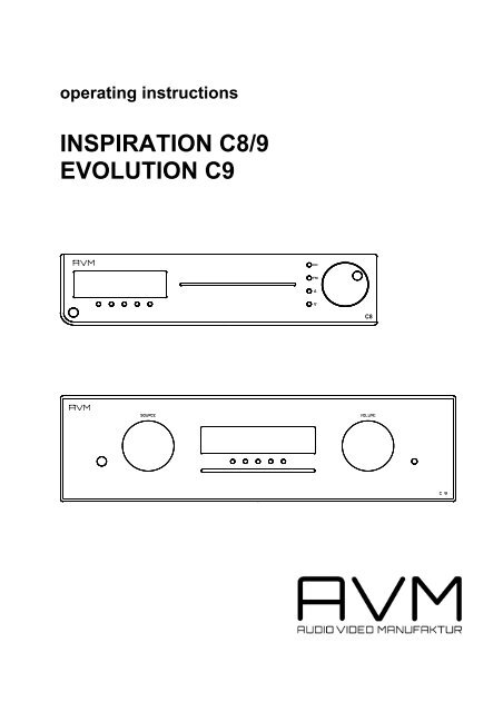
operating instructions<br />
INSPIRATION <strong>C8</strong>/9<br />
EVOLUTION C9<br />
CD<br />
FM<br />
<strong>C8</strong>
Dear customer,<br />
thank You for purchasing this <strong>AVM</strong> product. You own now a versatile, excellent sounding hifi<br />
component. Before enjoying music, please read this manual carefully. After that You will know how<br />
to use Your new <strong>AVM</strong> component in the optimal way.<br />
Sincerely Yours<br />
Your <strong>AVM</strong>-Team<br />
CAUTION : This unit contains a class 1 laser diode. Do not open. Invisible laser radiation can damage<br />
Your eyes.<br />
Laser diode Type : Ga-Al-As<br />
Wavelength : 755 - 815 nm (@ 25 °C)<br />
Output power : 0,7 mW max.<br />
NOTE: Use only high quality cables for connection between the unit and the other components of<br />
Your hifi set. We recommend cable lengths under 50 cm to avoid interference which can affect the<br />
reception of radio and TV tuners.<br />
Declaration of conformity (for EC only)<br />
We herewith confirm, that the unit to which this manual belongs fulfills the EC rules necessary to<br />
obtain the sign<br />
the necessary measurements were taken with positive results.<br />
<strong>AVM</strong> <strong>Audio</strong> Video Manufaktur GmbH, Daimlerstraße 8, D-76316 Malsch<br />
www.avm-audio.com, info@avm-audio.com<br />
2
Table of contents page<br />
Preamble 2<br />
Table of contents 3<br />
1. Basic information 4<br />
1.1 Mechanical construction 4<br />
1.2 Power supply 4<br />
1.3 Preamplifier 4<br />
1.4 Power amplifier 4<br />
1.5 CD-player, D/A-converter 5<br />
1.5.1 Quantization noise 5<br />
1.5.2 Reduction of jitter 5<br />
1.5.3 Filtering 6<br />
1.5.4 D/A-conversion 6<br />
1.6 Tuner 6<br />
2. Control & operating elements 7<br />
2.1.1 INSPIRATION <strong>C8</strong> 7<br />
2.1.1 EVOLUTION C9 8<br />
2.2 Pin configuration of connectors 8<br />
2.3 Installation and cooling 9<br />
2.4 Connection to mains 9<br />
2.5 Connecting analogue sources 9<br />
2.6 Connecting digital equipment 9<br />
2.7 Connecting a recorder 10<br />
2.8 Connecting processors / equalizers 10<br />
2.9 Connecting subwoofers 10<br />
2.10 Connecting the loudspeakers 10<br />
2.11 Connecting tuner antenna 10<br />
3. Basic operation 11<br />
3.1 First operation / self test 11<br />
3.2 Switching on / standby 11<br />
3.3 Selecting the signal source 11<br />
3.4 Volume setting 11<br />
3.4.1 Setting of input sensitivity 11<br />
3.5 Tuner 12<br />
3.5.1 Tuning 12<br />
3.5.2 Station memory 12<br />
3.5.3 Selecting a station 12<br />
3.6 CD-player 13<br />
3.6.1 Insert / eject 13<br />
3.6.2 PLAY, PAUSE, STOP 13<br />
3.6.3 SKIP / SEARCH 13<br />
3.6.4 Programming a playlist 14<br />
3.6.5 Random play 14<br />
3<br />
page<br />
4. Menu system 15<br />
4.1 Repeat 15<br />
4.2 RDS-Display 15<br />
4.3 Scanmode 15<br />
4.4 2-CH-Mode 15<br />
4.5 Bandwidth 15<br />
4.6 Sensitivity 15<br />
4.7 Tone Control 15<br />
4.8 Bass 15<br />
4.9 Treble 15<br />
4.10 Loudness 16<br />
4.11 Balance 16<br />
4.12 Set poweramp 16<br />
4.13 Set processor 16<br />
5. Remote control 16<br />
6. Cleaning 17<br />
7. If something doesn't work..... 17<br />
8. Conditions of warranty (EC only) 18<br />
9. Technical data 19<br />
10. Appendix 20<br />
10.1 Personal setup 20<br />
10.1.1 Set display brightness 20<br />
10.1.2 bass & treble control 20<br />
10.1.3 skip unused inputs 20<br />
10.1.4 define input names 20<br />
10.1.5 gain fix / variable 20<br />
10.1.6 FM auto store 21<br />
10.1.7 Set autoplay 21<br />
10.2 Reset 21
1. Basic information<br />
1.1 Mechanical construction<br />
The case is fully made of aluminium. The audio-connectors are all gold plated to minimize electrical losses<br />
and provide long lasting perfect contacts.<br />
1.2 Power supply<br />
A switch mode power supply delivers clean, hum-free electrical energy for the digital and analogue sections<br />
of D/A-converter and the preamplifier. All voltages are additionally buffered by large capacitors directly in the<br />
circuitry where they are needed.<br />
The power amplifiers of <strong>C8</strong> also are fed by a separate switch mode power supply. The C9 is equipped with<br />
two independent switch mode power supplies - one for each power amplifier.<br />
This concept guarantees that independently of the demanded output power the power amplifier has no<br />
influence on the preamplifier or the D/A-converter.<br />
1.3 Preamplifier section<br />
The input circuits act extremely fast and use special semiconductors for exact and nearly noise free sound<br />
reproduction. SMD technique allows a very compact circuit layout and thus extremely short signal paths.<br />
The volume control is done by highly precise integrated circuits. They allow setting in 0,5 dB steps and their<br />
channel balance is better than 0,05 dB. All this provides an absolutely precise, musical sound reproduction<br />
from lowest to highest listening levels.<br />
If You whish to correct the frequency response at low listening levels or to have more or less treble or bass,<br />
You can activate the sound processor and set the frequency response. For linear reproduction the whole<br />
circuitry is removed out of the signal path by relays and has absolutely no influence.<br />
1.4 Power amplifier<br />
<strong>C8</strong> and C9 use for each channel a separate powerful and efficient digital class-D amplifier. These amplifiers<br />
have an analog feedback loop from output to input. This ensures a nearly load-independent frequency<br />
response and a very good damping factor.<br />
Further highlights are very low output noise, low distortion and an extremely good efficiency. Even when<br />
delivering peak power levels to the speakers they deliver over 90% of the supplied energy to the speakers<br />
and thus produce nearly no heat.<br />
4
1.5 CD player / D/A- converter<br />
<strong>C8</strong> and C9 are equipped with upsampling circuitry and highly precise a/d converters. The theory of function<br />
will be described in the following text. If You are not interested in technical details, skip these chapters and<br />
simply listen to the music. You will discover Your CD collection anew! And that is what we want to achieve.<br />
Because application of new technologies is not just a gimmick but offers audible and measurable<br />
advantages to the listener.<br />
1.5.1 Quantization noise<br />
The quantity of information on a CD is defined by the audio format of 44,1 kHz sampling rate and 16 bits of<br />
resolution. Additional information (i.e. higher resolution or bandwidth) cannot be created by any electronic<br />
circuitry playing back such a CD. It is a fact that conventional d-/a converter systems do not fully reproduce<br />
the given information. This has several reasons: Converting a digital signal to an analogue signal produces<br />
analogue noise. This is because the digital (quantized) values which represent the signal are discrete with a<br />
very fine – but nevertheless limited - resolution. Therefore exist slight deviations in respect to the analogue<br />
original signal which was continuous (means infinite resolution). These deviations are random and cause an<br />
additional noise to the original signal when it is converted from the digital domain to the analogue domain.<br />
This kind of noise is called quantization noise.<br />
The characteristic of this noise is that it has an energy which depends on the resolution used to quantize the<br />
original signal and which is continuously spread over the whole range of the sampling frequency bandwidth.<br />
It is obvious that this noise can mask fine details of the originally recorded music.<br />
For physical reasons it is not possible to avoid quantization noise. Also a reduction of the total noise energy<br />
is not possible because the noise has been created when the signal was recorded. An elegant solution of<br />
this problem is to increase sampling frequency when re-converting the signal from digital to analogue. The<br />
upsampling converter installed increases sampling frequency from 44,1 kHz / 16 Bits up to 192 kHz / 24 Bits.<br />
When re-converting the upsampled signal the upsampling converter produces the same amount of noise<br />
energy as a conventional converter.<br />
The difference is that the noise energy is spread over a much broader frequency band. So the part of noise<br />
energy which is within the audible spectrum decreases. You can imagine that like if You have a certain<br />
volume of fluid in a small glass. If You fill the fluid in a glass which has much more diameter the quantity of<br />
fluid doesn’t change but height of the fluid surface will be lower than in the small glass. In the same way the<br />
increasing of sampling frequency (called upsampling) broadens the noise bandwidth and reduces the noise<br />
level. Most of the noise energy now is located in a frequency region beyond the audible range and can easily<br />
be filtered out without affecting the music signal.<br />
1.5.2 Reduction of jitter<br />
Jitter means slight, varying deviations in the sampling frequency of a digital signal. These deviations come<br />
from deviations in speed of the CD when it is played back (a natural effect, which can be reduced by<br />
mechanical means, but never fully eliminated). They can additionally come from electronic circuits through<br />
which the signal must pass. When such a signal is converted to analogue the samples arrive sometimes a<br />
little bit too early, sometimes a little bit too late at the DAC. This leads to modulations in the analogue signal<br />
which can affect the quality of the reproduced music. The spatial image is not precise, You cannot exactly<br />
locate the instruments, the sound is a bit roughened.<br />
The solution for this problem is upsampling. Upsampling does not only mean multiplying of sampling<br />
frequency by a fixed factor like it is done by the oversampling technique used in former times. Upsampling<br />
technique is more similar to recording the original digital signal anew with a different sampling frequency (reclocking).<br />
That means that the sampling frequency of the original signal and the upsampled signal are fully<br />
independent of each other. Thus if the upsampling converter has a stable jitter free clock the upsampled<br />
signal contains less jitter than the original digital signal.<br />
The musical advantages of re-clocking are the second reason why the <strong>AVM</strong> <strong>C8</strong> and C9 are equipped with a<br />
brand-new upsampling circuitry and an additional stable oscillator circuit.<br />
5
1.5.3 Filtering<br />
If a digital signal is converted to analogue the analogue signal contains not only the original signal, but as<br />
well it’s mirror image which lies in the frequency domain beyond one half of the sampling frequency. This<br />
mirror image (aliasing) can cause unwanted interference with the original signal and thus must be filtered out<br />
before passing the signal to the amplifier.<br />
If the original sampling rate of 44,1 kHz is used the filter slope must be positioned somewhat above 20 kHz<br />
and has to be very sharp in order to let the audio signal pass and to eliminate the aliasing components. Such<br />
filters cause a large phase deviation at the end of the pass band and have often also amplitude deviations.<br />
This leads to a harsh reproduction of music and can also affect the localization of solo instruments and<br />
voices.<br />
Upsampling to higher rates makes it possible to set the filter frequency far out of the audio signal range. For<br />
example at 192 kHz sampling rate the filter must take effect at 96 kHz. In this frequency region no music<br />
signal is present. Thus the filter can theoretically not affect musical reproduction.<br />
1.5.4 Digital- / analogue conversion<br />
<strong>C8</strong> and C9 use highly precise 24-bit differential converters to reproduce the analogue signal out of the digital<br />
data. Two converters on the same chip are used to output balanced signals. These signals are fed into a<br />
differential amplifier. The difference between the signals is twice the audio signal (because one of the signals<br />
is inverted) and the difference of the inaccuracies of the converters. As the two converters are on the same<br />
chip, their inaccuracy is nearly the same and thus also nearly eliminated by the differential amplifier.<br />
The second advantage of this differential technique is that the (very low) individual noise coming from the<br />
converters is reduced by 3 dB.<br />
The result is a clearly audible advantage in dynamic of the music signal and an audibly improved<br />
reproduction of the finest details.<br />
1.6 FM-Tuner<br />
The tuner can be adapted to different reception situations. You can set bandwidth, and sensitivity values in<br />
order to achieve optimal sound quality from aerial antenna as well as from cable. With it’s high sensitivity the<br />
tuner can also work with a simple indoor antenna.<br />
The stereo decoder offers high channel separation as well as very low noise.<br />
The RDS section (audio data system, not available in all countries) is processor controlled and shows You<br />
station names and texts with additional information about the program You are listening to.<br />
The station memory allows You to store up to 63 stations. It stores not only their frequency, but also the<br />
individual setting of sensitivity, bandwidth and mode (mono/stereo).<br />
6
2. Control & operating elements<br />
2.1.1 INSPIRATION <strong>C8</strong><br />
The numbers in the drawings below mark the control elements. They refer to the numbers in the text, where<br />
the operation of the unit is described.<br />
1 2<br />
3 4<br />
5<br />
1 Power button (on / off)<br />
2 Control LED<br />
3 Display<br />
4 Multifunctional button (soft key)<br />
5 Multifunctional button (soft key)<br />
6 Multifunctional button (soft key)<br />
7 Multifunctional button (soft key)<br />
8 Multifunctional button (soft key)<br />
GND<br />
FM<br />
15 16 17<br />
PHONO<br />
18<br />
IN1<br />
6<br />
IN2<br />
19<br />
7<br />
IN3<br />
8<br />
PLAYER<br />
SUPPLY<br />
20<br />
21<br />
OUT<br />
IN<br />
PLAYER PLAYER<br />
AUDIO VIDEO<br />
+ RIGHT - SPAKERS - LEFT +<br />
15 Ground socket for turntable chassis<br />
16 Antenna socket<br />
17 Phono input<br />
18 High level analogue inputs<br />
19 Speaker terminals<br />
20 Supply output for music players (USB)<br />
21 <strong>Audio</strong> input for music player<br />
22 Video in/out for music player<br />
23 Output for recorder (fixed level)<br />
24 Pre amplifier output<br />
25 Power amplifier input<br />
22<br />
9<br />
FIX OUT<br />
23<br />
PRE OUT MAIN IN<br />
24<br />
7<br />
10<br />
11<br />
12<br />
13<br />
CD<br />
FM<br />
9 CD-slot<br />
10 Source selector CD<br />
11 Source selector FM (tuner)<br />
12 Selector UP<br />
13 Selector DOWN<br />
14 Volume knob<br />
25<br />
26<br />
DIGITAL INPUTS<br />
RS 232<br />
EXT IR<br />
DIGIAL OUTPUTS<br />
TRIGGER OUT<br />
27 28 29303132<br />
33<br />
34<br />
14<br />
26 Digital input USB<br />
27 RS 232 connector<br />
28 Digital input RCA Cinch<br />
29 Digital input optical<br />
30 Connector for external IR-sensor<br />
31 Digital output RCA Cinch<br />
32 Trigger outputs<br />
33 Digital output optical<br />
34 Mains switch<br />
35 Mains connector<br />
I<br />
O<br />
35<br />
<strong>C8</strong>
2. Control & operating elements<br />
2.1.2 EVOLUTION C9<br />
The numbers in the drawings below mark the control elements. They refer to the numbers in the text, where<br />
the operation of the unit is described.<br />
1<br />
1 Power button (on / off)<br />
36 source selector<br />
2 Control LED<br />
3 Display<br />
4 Multifunctional button (soft key)<br />
5 Multifunctional button (soft key)<br />
6 Multifunctional button (soft key)<br />
36 2 3 4 5 6 7 8 9<br />
14<br />
8<br />
36<br />
7 Multifunctional button (soft key)<br />
8 Multifunctional button (soft key)<br />
9 CD-slot<br />
14 Volume knob<br />
36 Phones output<br />
15 16 17 18 19b 19a 20 21 22 23 24 25 26 28 29 31 33 27 30 32 34 35<br />
15 Ground socket for turntable chassis<br />
16 Antenna socket<br />
17 Phono input<br />
18 High level analogue inputs<br />
19a Speaker terminals<br />
19b Speaker terminals<br />
20 Supply output for music players (USB)<br />
21 <strong>Audio</strong> input for music player<br />
22 Video in/out for music player<br />
23 Output for recorder (fixed level)<br />
24 Pre amplifier output<br />
2.2 Pin configuration of connectors<br />
Connector for external IR-sensor (30)<br />
3,5mm stereo<br />
infrared input<br />
GND<br />
IR-Signal +5V supply<br />
25 Power amplifier input<br />
26 Digital input USB<br />
28 Digital input RCA Cinch<br />
29 Digital input optical<br />
31 Digital output RCA Cinch<br />
33 Digital output optical<br />
27 RS 232 connector<br />
30 Connector for external IR-sensor<br />
32 Trigger outputs<br />
34 Mains switch<br />
35 Mains connector<br />
Trigger outputs (32)<br />
3,5mm mono<br />
trigger outputs<br />
GND<br />
+8V trigger<br />
I<br />
O
2.3 Installation and cooling<br />
The unit can become hot depending on demanded output power / environmental temperature. Therefore it is<br />
important, that the cooling air can flow unhinderedly into the air inlet in the bottom and flow out through the<br />
holes in the rear panel. Direct exposure to sunlight is not recommended because this will heat up the unit.<br />
2.4 Connection to mains<br />
Connect the unit to the mains outlet by using the power cord which is (in some countries) delivered together<br />
with the unit. Make sure that mains voltage is according to the value printed on the rear panel of the amp<br />
(near mains connector). Let the unit be switched off until all audio connections are made.<br />
2.5 Connecting the analogue signal sources<br />
High level sources<br />
Connect the outputs of Your signal sources to the inputs (18). The upper row is for left channel, the lower<br />
row is for right channel.<br />
Turntable<br />
Connect the output of Your turntable with phono inputs (17) and connect the chassis ground wire to the<br />
ground connector (15). The <strong>C8</strong>/C9 phono input is suitable for MM cartridges as well as for high and medium<br />
level MC cartridges. Sensitivity can be adjusted (see 3.4.1).<br />
Music player<br />
To connect a music player / cell phone to the nit you must use an adapter cable. The USB connector (if<br />
equipped) should be connected to the USB supply output (20), the audio outputs of the player are connected<br />
to the input sockets (21). In case the player has a video output, You can connect it to the video input (22)<br />
and the monitor to the video output right above.<br />
For optimal performance adjust the output of Your player to maximum.<br />
2.6 Connecting digital equipment<br />
Inputs SPDIF/ (RCA Cinch, optical)<br />
Connect the outputs of Your digital sources to the corresponding inputs of the <strong>C8</strong>/C9 (28, 29).<br />
USB connector<br />
Use a suitable USB cable and connect the USB input (26) to your computer. PC working with WINDOWS XP<br />
or higher as well as most Apple computers recognize the USB input automatically. Installation of a special<br />
driver software is normally not necessary.<br />
To play music stored on your computer you must set it's output to USB and the volume to maximum. These<br />
settings and how to create playlists, how to play certain music titles depend on the software you use. Please<br />
refer to the corresponding software manual.<br />
Digital out<br />
The input of a digital recorder must be connected to the output digital outputs (31, 33). The signal on the<br />
digital outputs depends the selected source (build in CD, dig in).<br />
9
2.7 Connecting a recorder<br />
Connect the recorder’s output to one of the inputs (18). The inputs of the recorder must be connected to the<br />
fixed level outputs (23).<br />
2.8 Connecting processors / equalizers<br />
Connect the processor’s outputs to the inputs main in (25). The inputs of the processor must be connected to<br />
the outputs pre out (24). Additionally You must activate the processor loop (see 4.13)<br />
2.9 Connecting subwoofers<br />
Active subwoofers<br />
If you use an active subwoofer (with built in power amplifier), simply connect it's inputs to the unit's pre out<br />
(24) and adjust the bass level at the subwoofer. If the subwoofer has a trigger input, connect it to the trigger<br />
output (32, see also chapter 2.2).<br />
Active subwoofers with built in cross over<br />
Most active subwoofers have a built in frequency divider network. They receive the full range signal from the<br />
amplifier and feed the filtered signal (full range minus bass) back. This kind of subwoofer can be connected<br />
to the processor in / output: Connect the subwoofer's inputs to the pre outputs (24) and the subwoofer's<br />
outputs to the main inputs (25). Additionally You must activate the processor loop (see 4.13)<br />
If the subwoofer has a trigger input, connect it to the trigger output (32, see also chapter 2.2).<br />
2.10 Connecting the loudspeakers<br />
INSPIRATION <strong>C8</strong><br />
Connect the speakers to the speaker terminals (19). Use only good speaker cables with sufficient diameter.<br />
Make sure, that the red terminals are connected to the red or “ + “ terminals of the speakers and the black<br />
terminals to the black or “ – “ terminals of the speakers.<br />
EVOLUTION C9<br />
The C9 has two switchable speaker outlets. Connect one pair of the speakers to the speaker terminals (19a),<br />
the other one to the terminals (19b). Use only good speaker cables with sufficient diameter. Make sure, that<br />
the red terminals are connected to the red or “ + “ terminals of the speakers and the black terminals to the<br />
black or “ – “ terminals of the speakers.<br />
The outputs can be activated or deactivated via the menu (see 4.12)<br />
2.11 Tuner antenna<br />
Connect the Antenna cable to the antenna socket (16)<br />
10
3. Basic operation<br />
3.1 First operation / self test<br />
In case the <strong>C8</strong>/C9 was not connected to mains a self test will be performed when it is switched on by mains<br />
switch (34) for the first time. The unit checks it’s configuration and if all installed components work properly.<br />
The procedure is shown in the display. After that the unit will switch to stand by.<br />
3.2 Switching on / standby<br />
Using the button power (1) You can switch between on (operate) and stand by. In the on state the display (3)<br />
lights up and the LED (2) is off. In stand by mode the display (3) is off and the LED is on to indicate that the<br />
unit is still connected to mains.<br />
CAUTION: When switched to stand by the unit is still connected to mains. In case of thunderstorm or if You<br />
leave the house for a longer time we recommend that You switch the amplifier off by using the mains switch<br />
(30) or pull the mains plug.<br />
3.3 Selecting the signal source<br />
INSPIRATION <strong>C8</strong>: Use the source selector keys (12, 13) to select a signal source. For selecting Tuner or<br />
CD use the direct access keys 10 / 11.<br />
EVOLUTION C9: Use the rotary switch (36) to select a signal source.<br />
The selected source is indicated in the display (3).<br />
NOTES: If you switch to another source while laying a CD, the drive will stop first. This may take a few<br />
seconds. If you activate a digital input that has no valid signal "NO DIG SIGNAL" is indicated in the display<br />
(3). In this case the volume cannot be changed.<br />
3.4 Volume setting<br />
Use the rotary encoder (14) to set the desired volume. Depending on rotating speed the volume increases /<br />
decreases in 0,5 dB steps (slow) or 2 dB steps (fast). The actual setting is shown in the display (3).<br />
3.4.1 Setting of input sensitivity<br />
The level of signal sources differs often by several dBs. So You recognize a step in volume, when switching<br />
between two inputs. With the sensitivity setting menu You can avoid this. The sensitivity of each input can be<br />
adjusted between – 9.5 dB and + 10.0 dB.<br />
Select any input (but NOT the Tuner or CD) and chose a convenient volume level. Now press the button<br />
MENU (6, under the display) for more than 2 seconds. The button is now marked "EXIT LVL". Pressing this<br />
button again will exit the level setting mode and bring the unit back to normal operating mode.<br />
While level setting is active the display shows the actual level instead of the volume. Level can be set using<br />
the volume knob (6). Now you can switch between the sources (also CD and tuner) and adjust the levels.<br />
When this is done press the "EXIT LVL" knob and bring the unit back to normal operating mode. All level<br />
settings are now stored.<br />
NOTE: While the level setting mode is active the unit will not respond to any remote control command.<br />
11
3.5 Tuner (if built in)<br />
The basic functions of the tuner can be accessed by the buttons right under the display (4 – 8). For more<br />
sophisticated functions see chapter 4.4 to 4.8<br />
3.5.1 Tuning<br />
Depending on the selected mode (manual / auto, see 4.2) the most right buttons (7, 8) under the display (3)<br />
are named AUT or MAN. In AUT-mode a tip on one of the buttons lets the tuner automatically seek<br />
the next upper or lower station. In MAN mode the frequency changes in 50 kHz-steps as long as the button<br />
is pressed. In this case the tuning indicator shown in the display (3) helps You to tune correctly to the desired<br />
station. If tuning is correct it will show "locked“.<br />
NOTE: To optimize the sound quality You can use the functions mode, sensitivity and bandwidth, which<br />
are described later on in chapter 4.4 to 4.8<br />
3.5.2 Station memory<br />
Storing a new station<br />
If You want to store a certain station in the memory, press the button MENU (6) under the display (3) for<br />
more than 2 seconds. The display will propose the next free memory position for storage (for example: if 5<br />
stations are already stored position 6 will be proposed). Using the "MOVE" buttons (4, 5) you can change the<br />
position.<br />
Modifying, moving or deleting an existing station<br />
If the tuner is set to an already stored station you can change it's settings, move it to a different position or<br />
delete it. If you, want first change settings (mono/stereo, bandwidth or other). Then press the button MENU<br />
(6) under the display (3) for more than 2 seconds. If you then press "STORE" the station will be stored anew<br />
at the old position with the changed settings. Using the buttons "MOVE" allows you to change the position of<br />
this station before storing. "DELETE" will erase the station out of the memory. "EXIT" will bring the unit back<br />
to normal operating mode without changing the memory.<br />
NOTE: The station memory allows You to store up to 63 stations. It stores not only their frequency, but also<br />
the individual setting (mono/stereo, bandwidth or other).<br />
3.5.3 Selecting a station out of the memory<br />
The buttons STAT (4, 5) select the stations stored in the memory. A short tip switches to the next /<br />
previous station. Holding the button down scans automatically up / down. The number of the actual station is<br />
shown in the display ("STAT xx").<br />
12
3.6 CD player<br />
The basic functions of the CD player can be accessed by the buttons right under the display (4 – 8). For<br />
more sophisticated functions see chapter 4.<br />
3.6.1 Insert / eject<br />
Insert a CD<br />
The <strong>C8</strong> / C9 have a slot-in CD drive. Insert the CD (coverside up) and push slightly. The drive will now<br />
automatically draw the disc inside. After that the player reads the TOC and shows it on the display. Most left<br />
is the number of the actual track followed by the total number of tracks on the CD (for example "1/17"). The<br />
middle f the display shows the total playing time of the CD.<br />
NOTE: If there is still a CD inside or the unit is in stand by, the slot will be blocked. If the inserted disc is not<br />
readable (DVD, data-CD) the display will show "no playable disc"<br />
Eject CD<br />
Press the button (7) under the display (3). Then the disc will be ejected.<br />
Auto-CD function<br />
If CD is not selected as source he unit will automatically change to CD from any other input after you have<br />
inserted a CD.<br />
3.6.2 PLAY, PAUSE, STOP<br />
While the player is stopped the buttons or (4, 5) select the title. A short tip switches to the next /<br />
previous title. Holding the button down scans automatically up / down. The number of the actual title is<br />
shown in the display.<br />
Pressing (8) starts the player. While playing the button changes it’s function to (pause).<br />
While the player is playing the button (7) under the display shows the STOP-symbol. When the player is<br />
stopped this button changes it’s function to EJECT-symbol.<br />
3.6.3 SKIP / SEARCH<br />
While the player is stopped the buttons or (4, 5) select the title. A short tip switches to the next /<br />
previous title. Holding the button down scans automatically up / down. The number of the actual title is<br />
shown in the display.<br />
While the player is playing a short tip on the buttons or (4, 5) selects the previous / next title. Holding<br />
down the buttons starts the rewind / fast forward function. Rewind / fast forward stops automatically when the<br />
begin / end of the actual title is reached.<br />
13
3.6.4 Programming an individual playlist<br />
If a disc is inside the player You can program Your individual playing sequence as follows: Hold the button<br />
"MENU" (6) down for more than 2 seconds to enter the playlist-menu.<br />
The display shows on the left side the actual title ("TRCK"), below the playing time of this title ("TIME").<br />
Pressing the buttons SELECT (4, 5) allows You to select a title.<br />
Pressing "ADD" (6) adds the selected title to the playlist. The display shows on the right side the number of<br />
programmed titles ("PGM-QTY"), below the playing time of the programmed list ("P-TIME").<br />
The button "STORE" (7) stores the playlist.<br />
NOTE: The program function is only available while the player is stopped. The maximum number of<br />
programmed tracks is 99, the maximum program duration is 99 minutes. In case the Level setting is active<br />
You must exit first (see 3.4.1).<br />
EXAMPLE:<br />
The CD inside the player contains 15 titles. You want to play only titles 7, 3 and 8.<br />
• Press MENU (6) for more than 2 seconds. The display now shows “TRCK 1/15”.<br />
• Select title 7 using the buttons SELECT (4, 5). Display shows “TRCK 7/15”.<br />
• Now add this track (pressing "ADD" (6)) to the playlist.<br />
• Select title 3 using the buttons SELECT (4, 5). Display shows “TRCK 3/15”.<br />
• Now add this track (pressing "ADD" (6)) to the playlist.<br />
• Select title 8 using the buttons SELECT (4, 5). Display shows “TRCK 8/15”.<br />
• Now add this track (pressing "ADD" (6)) to the playlist.<br />
• Now press STORE (7) to finish the programming and store the playlist.<br />
Deleting an existing playlist<br />
Press MENU (6) for more than 2 seconds. Then press DEL PGM (8) and the playlist is deleted.<br />
3.6.5 Random play<br />
Press MENU (6) for more than 2 seconds. Then press RANDOM (7). Now a random playlist will be<br />
generated.<br />
Deleting a random playlist<br />
Press MENU (6) for more than 2 seconds. Then press DEL PGM (8) and the random playlist is deleted.<br />
14
4. Menu system<br />
The <strong>C8</strong>/C9 offer a lot of custom specific settings in their menu system. To enter the menu just tip on the<br />
button MENU (6). The button now changes to EXIT. A second tip on this button leads You to the normal<br />
operating mode. When the menu system is active You can select the desired function using the buttons<br />
ITEM (4, 5). The setting is done using the buttons VALUE (7, 8).<br />
Depending on the actual source the menu system offers the following settings:<br />
4.1 Repeat (CD must be selected as source)<br />
Choose repeat mode: "one" (actual title), "all" (whole CD or programmed sequence), "off".<br />
4.2 RDS-Display (tuner must be selected as source)<br />
Choose if station NAME, RDS-TEXT or FREQUENCY is displayed.<br />
4.3 Scanmode (tuner must be selected as source)<br />
Set tuning mode between "auto" or "manual". (See also 3.5.1 tuning)<br />
4.4 2-CH-Mode (tuner must be selected as source)<br />
Set tuner to mono or stereo to obtain best sound.<br />
NOTE: Depending on actual setting the threshold for auto tuning will change (sensitive in MONO, less<br />
sensitive in STEREO).<br />
4.5 Bandwidth (tuner must be selected as source)<br />
Select bandwidth "narrow" / "wide" for best reception.<br />
4.6 Sensitivity (tuner must be selected as source)<br />
Choose between "local" (in case the tuner operates from a cable) and "distant" (if operated from antenna)<br />
4.7 Tone control (see also 10.1.6)<br />
Set tone control to "bypass" (= linear) or "active". In case the tone control is activated "TONE ON" is shown<br />
in the display (4), otherwise "LINEAR".<br />
You can choose if you want to change bass and treble settings simultaneously for all inputs ("global") or<br />
especially for the actual input ("individual"). See 10.1.6<br />
The loudness function depends on speakers and properties of the listening room and is therefore always<br />
"global".<br />
NOTE: In case tone control is set to "bypass" the menu will skip the bass, treble, and loudness settings (4.8 -<br />
4.10).<br />
Set tone control to "bypass" (= linear) or "active". In case the tone control is activated a "TONE ON" is shown<br />
in the display (3).<br />
4.8 Bass<br />
Set bass level between – 5 and + 9.<br />
4.9 Treble<br />
Set treble level between – 7 and + 7.<br />
15
4.10 Loudness<br />
If You listen to music at low levels, You often recognize that bass and treble reproduction are weak. This is<br />
because the human ear is not sensitive to bass and treble at low sound levels. To compensate this You can<br />
use the parametric loudness function of the C6m. This function will increase bass and treble levels when You<br />
decrease the volume. When the volume is increased the frequency response will be more and more flat and<br />
remain linear at high volume levels. In order to obtain best results You have to proceed in the following way:<br />
Set the amplifier to a moderate volume level. Using the buttons VALUE (7, 8) choose in the loudness<br />
menu a curve ( "of" and 1 to 9) which gives best sound impression and exit the menu (button EXIT (6)).<br />
NOTE: The loudness function selects automatically the correct curve depending on actual volume setting. So<br />
if You change volume a different curve than previously selected may be shown in the loudness menu. This is<br />
not a malfunction.<br />
4.11 Balance<br />
Set the balance between right and left channel for optimal stereo image.<br />
4.12 Set poweramp<br />
INSPIRATION <strong>C8</strong><br />
You can set the poweramp ON or OFF. This is useful if you have connected a headphone amp or a separate<br />
power amplifier to the pre out (24).<br />
EVOLUTION C9<br />
Activate / deactivate the two speaker outputs (19a, 19b).<br />
4.13 Set processor (see also 2.8, 2.9)<br />
Switches processor function "on" / "off". If the processor is activated, it influences the signals on the speaker<br />
outputs. The signals on fix out (23) are not affected.<br />
5. Remote control<br />
The main functions of the <strong>C8</strong>/C9 can be controlled by the RC3: ON/OFF, Volume control, source select,<br />
Station select, PLAY/PAUSE, STOP, SKIP.<br />
The RC3 works up to distances of 7 meters. For best function point with the RC3 to the front panel of your hifi<br />
set. If the hi-fi set doesn’t react or reacts only over short distances, the batteries of the RC3 must be<br />
changed.<br />
Changing batteries<br />
Bottom view<br />
Unscrew the 6 marked screws (CAUTION, do NOT unscrew the 2 unmarked screws in the middle). Take the<br />
bottom plate with the mounted pcb out. Remove the worn batteries and replace them with two new batteries<br />
(type CR2032, 3V Lithium cells). Make sure that polarity is correct (the "+" sign must be on top). Insert the<br />
bottom plate and screw it tight.<br />
16
6. Cleaning<br />
Use a soft cloth and normal glass cleansing fluid.<br />
CAUTION: Make sure that no fluid comes into the unit. Do not use scouring cleaners. They may<br />
damage the surface.<br />
7. If something doesn’t work.......<br />
Some putative defects are often caused by mistakes in operation. Sometimes other units connected to the<br />
amplifier can cause problems. Therefore please read the following tips before You consult Your dealer or us.<br />
1. Amplifier is muted<br />
a) Mute function is active, press button MUTE on remote control or increase volume using the rotary<br />
encoder (14)<br />
b) Power amplifier is switched off. Activate poweramp (see4.12).<br />
c) PROCESSOR function is activated. Switch processor off (see 4.13).<br />
d) Inadvertent switching to standby by remote control. Press power button (1). If the LED indicator and<br />
display do not light up a fuse can be blown due to overvoltage (thunderstorm). Please contact Your<br />
dealer.<br />
2. Amplifier switches off during normal operation<br />
This can happen if the temperature inside the unit becomes too high. In this case the amplifier switches off<br />
and the display shows “overheat”. Switch the unit off and let it cool down for five minutes.<br />
3. Hum<br />
a) Hum while playing records: Make sure that the chassis of Your record player is properly grounded.<br />
4. Infrared remote control doesn’t work<br />
a) Check the batteries of Your remote control transmitter<br />
b) Point with the remote control transmitter directly to the unit.<br />
17
8. Conditions of warranty (EC only)<br />
If despite expectations a defect occurs that cannot be repaired by yourself or your dealer, we undertake the<br />
repair of your unit free of charge for up to three years from date of purchase. The warranty covers the costs<br />
of material and working time, transport costs are to be borne by the owner.<br />
Provisions for this warranty are:<br />
• The unit must have been purchased from an authorized dealer. Equipment from other sources will not be<br />
repaired, not even at charge.<br />
• The warranty registration card, together with a copy of the bill of sale, must be received by us within four<br />
weeks of the date of purchase.<br />
• The defect must not have been caused by improper handling or misuse.<br />
• Return the unit to us only in its original packing. If this is not possible we are entitled to refuse<br />
acceptance. We will not assume responsibility for transport damage under any circumstances.<br />
• A short description of the defect is to be included with the returned unit.<br />
• In cases of doubt we reserve the right to request a copy of the bill of sale.<br />
• We also reserve the right to levy a handling charge for items returned without good or valid reason, or if<br />
the unit proves to be not defective.<br />
NOTE<br />
If you are returning the unit from a country other than Germany you should ensure that correct export<br />
documents are obtained. We cannot accept any charges for costs arising from improper or incomplete export<br />
documentation.<br />
If you have purchased your unit from a dealer outside Germany please refer to him or the relevant importing<br />
firm to process the warranty.<br />
18
9. Technical data inspiration <strong>C8</strong>/C9<br />
Amplifier<br />
Sensitivity (25 W/4 Ohm) 12.5 mV to 125 mV (adjustable)<br />
Sensitivity PHONO (25 W/4 Ohm) 40 µV to 400 µV (adjustable)<br />
Input impedance 6.8 kOhms<br />
Input impedance PHONO 47 kOhms / 100 pF<br />
S/N 96 dB (A)<br />
S/N PHONO 83 dB (A)<br />
Frequency response < 5 Hz - > 50 kHz<br />
THD (25 W/4 Ohm) < 0,1%<br />
Damping factor >100<br />
Output power <strong>C8</strong> 2x100 W (8 Ohms) / 2x150 W (4 Ohms)<br />
Output power C9 2x180 W (8 Ohms) / 2x300 W (4 Ohms)<br />
Tuner<br />
Frequency range 87,5 – 108,0 MHz<br />
Tuning step 50 kHz<br />
Sensitivity (mono / stereo) 1,5 µV / 50 µV<br />
S/N ratio (mono / stereo) 73 / 68 dB(A)<br />
THD+N mono / stereo) 0,1% / 0,3%<br />
Channel separation 55 dB<br />
CD / D/A converter<br />
Formats CD-<strong>Audio</strong>, CDR<br />
Upsampling 192 kHz / 24 Bit<br />
Frequency response 20 Hz – 20 kHz (up to 90 kHz depending on input sample rate)<br />
Deemphasis automatically<br />
Input format dig in opt SPDIF, linear PCM 33 kHz – 96 kHz / 16 – 24 bits<br />
Input format dig in coax SPDIF, linear PCM 33 kHz – 192 kHz / 16 – 24 bits<br />
USB input up to 48 kHz / 16 bits<br />
Input impedance dig in coax 75 Ohms<br />
Input level dig in coax according to IEC 908<br />
Digital-outputs 44,1 kHz / 16 Bit, or input format<br />
(S/PDIF, TOSLINK)<br />
General<br />
<strong>C8</strong><br />
Standby 1 VA<br />
max. 450 VA<br />
Power supply AC 230V / 50-60Hz<br />
(Upon request AC 115 V / 50-60 Hz)<br />
Dimensions (W x H x D) 340 x 80 x 350 mm<br />
Weight 6 kg<br />
C9<br />
Standby 1 VA<br />
max. 900 VA<br />
Power supply AC 230V / 50-60Hz<br />
(Upon request AC 115 V / 50-60 Hz)<br />
Dimensions (W x H x D) 430 x 130 x 370 mm<br />
Weight 7.5 kg<br />
issued: 11/2011. Changes reserved without notice<br />
19
10 Appendix<br />
10.1 Personal setup<br />
Several settings can be done in the personal setup<br />
To access the personal setup switch the unit to standby (power button (1)). Then press and hold the most<br />
right key under the display (8). While holding that key switch the unit on (power button (2)). The display now<br />
will show "**personal setup***". Release the button (8) and the unit is in personal setup mode.<br />
When the personal setup is active you can select the desired function using the buttons ITEM (4, 5). The<br />
button SELECT (8) activates the function. The setting is done using the buttons VALUE (7, 8). BACK<br />
(6) leads you back to other settings. EXIT (6) exits the personal setup and stores the settings.<br />
10.1.1 Set display brightness<br />
Sets display brightness 25% to 100%.<br />
NOTE: The setting 100% can lead to "burn in" effects on the display if the unit is operated in this setting for a<br />
very long time. So please switch the unit to stand by, if not in use.<br />
10.1.2 bass & treble control<br />
Choose if you want to change bass and treble settings simultaneously for all inputs ("global") or especially for<br />
the actual input ("individual").<br />
10.1.3 skip unused inputs<br />
Deactivate unused inputs ("SKIP"). The unit will then skip these inputs when the source selector (36) is<br />
rotated or if you select the inputs via the remote control.<br />
10.1.4 define input names<br />
You can individually set the names (max. 8 characters) of the different sources shown in the display (3).<br />
Proceed as follows:<br />
Press SELECT. The display shows now on the left side the old name, on the right side the new name. The<br />
character to change is marked by an underscore. The keys ITEM (4, 5) select the input, the keys<br />
POS (7, 8) select the position of the character to change. The marked character can be set using the<br />
volume knob (14). When You are ready, simply press BACK (6). and the new names will be stored.<br />
10.1.5 gain fix / variable<br />
In a surround system the channel balance, tone setting and bass management are done by the decoder.<br />
This setting must not be altered by another component because the channel balance the would be incorrect.<br />
For this application <strong>C8</strong> and C9 offer the fixed gain function (only for inputs 1-3).<br />
Set the input where the main channels of the surround system are connected to fixed gain. When this input is<br />
selected, tone controls are bypassed, balance is set to neutral position and the gain is on a fixed level<br />
independently f the volume setting on the other inputs.<br />
20
10.1.6 FM auto store<br />
This function is useful when storing a large quantity of stations from cable. Please note that the stations are<br />
stored including the actual tuner setting (see 4.1 - 4.5). For cable we recommend: RDS-display = name,<br />
scanmode = auto, 2-ch mode = stereo, bandwidth = narrow, sensitivity = local.<br />
Once the tuner parameters are set in the desired way enter the personal setup and select "FM auto store".<br />
Then press the button START (4). While the auto store function is in progress all stations are played audibly<br />
for half a second. When the function is terminated the display shows for 2 seconds the number if stations<br />
found. Then the unit comes back to normal tuner operating mode.<br />
If desired you can now shift certain stations to different positions, change the settings and store back or<br />
delete unwanted stations (see 3.5.2).<br />
10.1.7 Set autoplay<br />
When AUTOPLAY is ON, the CD player will start playing automatically every time a new CD is inserted. If<br />
AUTOPLAY is OFF, the player will read the TOC of the inserted disc and then go to STOP mode.<br />
10.2 Reset<br />
This function cancels certain or all settings and makes the unit return to default settings.<br />
To perform the reset switch the unit to standby (power button (1)). Then press and hold the middle key (6)<br />
under the display (3). While holding that key switch the unit on (power button (1)). The display now will show<br />
the reset menu.<br />
Select if you want to clear the station memory ("STAT"), the input names ("NAME") or reset the unit<br />
completely ("ALL").<br />
"CANCEL" will bring the unit back to normal operating mode without resetting any item.<br />
21