Relaxation of Shot Peening Induced Residual Stresses in Ti-6Al-4V ...
Relaxation of Shot Peening Induced Residual Stresses in Ti-6Al-4V ...
Relaxation of Shot Peening Induced Residual Stresses in Ti-6Al-4V ...

You also want an ePaper? Increase the reach of your titles
YUMPU automatically turns print PDFs into web optimized ePapers that Google loves.
<strong>Relaxation</strong> <strong>of</strong> <strong>Shot</strong> <strong>Peen<strong>in</strong>g</strong> <strong>Induced</strong> <strong>Residual</strong> <strong>Stresses</strong> <strong>in</strong> <strong>Ti</strong>-<strong>6Al</strong>-<strong>4V</strong> : Impact on Damage Tolerant Design<br />
M. J. Shepard *<br />
Air Force Research Laboratory, Materials and Manufactur<strong>in</strong>g Directorate, Wright-Patterson AFB, OH, 45433-7817<br />
Abstract<br />
The <strong>Ti</strong>-<strong>6Al</strong>-<strong>4V</strong> components commonly found <strong>in</strong> turb<strong>in</strong>e eng<strong>in</strong>es are frequently shot peened to <strong>in</strong>duce<br />
compressive residual stresses <strong>in</strong> the near surface regions <strong>of</strong> these components. Due to uncerta<strong>in</strong>ty regard<strong>in</strong>g the<br />
redistribution <strong>of</strong> residual stress fields <strong>in</strong> components dur<strong>in</strong>g service and the difficulties associated with<br />
<strong>in</strong>corporat<strong>in</strong>g residual stresses <strong>in</strong> design, no design credit is typically taken for these compressive residual stresses.<br />
In the current study, the redistribution <strong>of</strong> shot peen<strong>in</strong>g <strong>in</strong>duced residual stresses, is reported for two<br />
common peen<strong>in</strong>g conditions, both before and after isothermal exposures. The importance <strong>of</strong> the different <strong>in</strong>-depth<br />
residual stress pr<strong>of</strong>iles aris<strong>in</strong>g from different peen<strong>in</strong>g conditions and isothermal exposures is explored <strong>in</strong> terms <strong>of</strong> a<br />
simple damage tolerant design.<br />
It was found that useful compressive residual stresses persist well above the likely use temperature for this<br />
alloy. While it was found that substantial relaxation <strong>of</strong> shot peen<strong>in</strong>g <strong>in</strong>duced residual stresses do occur, residual<br />
compressive stresses rema<strong>in</strong> even after exposures as high as 200% <strong>of</strong> the expected use temperatures. These stresses<br />
are sufficient to yield substantial <strong>in</strong>creases <strong>in</strong> damage tolerant design life.<br />
Keywords: Fatigue, Fatigue Crack Growth, <strong>Residual</strong> Stress, <strong>Shot</strong> <strong>Peen<strong>in</strong>g</strong>, Stress <strong>Relaxation</strong>, Surface Treatments<br />
1. Introduction<br />
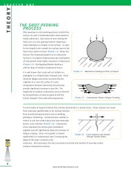
<strong>Shot</strong> peen<strong>in</strong>g is the most commonly used method for <strong>in</strong>duc<strong>in</strong>g compressive near surface residual stresses<br />
<strong>in</strong> turb<strong>in</strong>e eng<strong>in</strong>e components. A detailed review <strong>of</strong> the shot peen<strong>in</strong>g process and its many applications is beyond<br />
the scope <strong>of</strong> this article. However many references are available and the reader is referred to those. [1,2]<br />
It has long been observed that carefully called out, well controlled shot peen<strong>in</strong>g can yield many benefits<br />
<strong>in</strong>clud<strong>in</strong>g <strong>in</strong>creased mean high cycle fatigue (HCF) performance, reduced scatter <strong>in</strong> HCF performance, and<br />
* Correspond<strong>in</strong>g author: michael.shepard@wpafb.af.mil Air Force Research Laboratory, 2230 Tenth St., Suite 1,<br />
WPAFB, OH 45433-7817<br />
1
<strong>in</strong>creased tolerance to small flaws. This <strong>in</strong>creased damage tolerance is due to reduced stress <strong>in</strong>tensity factor ranges<br />
<strong>in</strong>duced by the shot peen<strong>in</strong>g <strong>in</strong>duced compressive residual stresses.<br />
S<strong>in</strong>ce many turb<strong>in</strong>e eng<strong>in</strong>e components are designed us<strong>in</strong>g damage tolerant design practices, it is<br />
desirable to <strong>in</strong>corporate the lower fatigue crack growth (FCG) rates and higher threshold stress <strong>in</strong>tensity factor<br />
ranges associated with shot peened surfaces <strong>in</strong>to design practice. In theory, the former factor could allow for<br />
longer design lives and/or longer <strong>in</strong>spection <strong>in</strong>tervals and the latter factor could allow for whether higher applied<br />
stresses with no predicted crack growth <strong>of</strong> slightly larger assumed flaws <strong>in</strong> the design. To date, the <strong>in</strong>corporation<br />
<strong>of</strong> these shot peen<strong>in</strong>g <strong>in</strong>duced compressive residual stresses <strong>in</strong> design has been the exception rather than the rule.<br />
There are many reasons for this.<br />
First, no widely accepted, nondestructive, subsurface residual stress analysis method exists that can<br />
measure the required residual stress pr<strong>of</strong>iles. Without such a method, it is impossible to verify that the subsurface<br />
residual stresses required for a given design are present <strong>in</strong> any given part. Second, it is not always certa<strong>in</strong> that the<br />
desired shot peen<strong>in</strong>g residual stresses are always imparted <strong>in</strong> geometrically complex locations, such as radii and<br />
through holes. This is because these regions are not only difficult to peen, they are also the most challeng<strong>in</strong>g for<br />
residual stress analysis. Unfortunately, these locations are <strong>of</strong>ten the life limit<strong>in</strong>g features s<strong>in</strong>ce they act as stress<br />
concentrations. Third, even when there is <strong>of</strong>ten considerable confidence <strong>in</strong> the orig<strong>in</strong>al residual stress pr<strong>of</strong>ile due<br />
to tight quality control and representative residual stress analysis it is difficult to know if there has been any<br />
deleterious redistribution <strong>of</strong> the residual stresses due to thermal exposure and/or small amounts <strong>of</strong> <strong>in</strong>elastic<br />
deformation from overload <strong>in</strong>duced plasticity or creep. Additionally, although the feasibility <strong>of</strong> <strong>in</strong>corporat<strong>in</strong>g<br />
known residual stresses <strong>in</strong> fracture mechanics calculations has been demonstrated by a number <strong>of</strong> authors [3,4,5,6]<br />
further experimental work is required to validate the current l<strong>in</strong>ear elastic fracture mechanics (LEFM) based<br />
approaches and develop more complex approaches that will be accurate <strong>in</strong> the complex multiaxial applied and<br />
residual stress states exist<strong>in</strong>g <strong>in</strong> real hardware. F<strong>in</strong>ally, among many day-to-day users <strong>of</strong> shot peened components<br />
there is a general hesitancy to take design credit for these compressive stresses s<strong>in</strong>ce they exist <strong>in</strong> such a physically<br />
th<strong>in</strong> region, which might be subject to redistribution due to handl<strong>in</strong>g damage or some other event.<br />
The current study will not attempt to address all these admittedly non-trivial issues. Rather the current<br />
study will focus on the <strong>in</strong>itial compressive residual stress pr<strong>of</strong>iles produced by common aerospace peen<strong>in</strong>g<br />
2
conditions and how these pr<strong>of</strong>iles are altered by isothermal exposures. If these residual stresses are compromised<br />
excessively at the required operat<strong>in</strong>g temperatures, little design benefit will rema<strong>in</strong>. The impact <strong>of</strong> these<br />
temperature <strong>in</strong>duced stress redistributions on damage tolerant design life will be explored us<strong>in</strong>g LEFM calculations<br />
<strong>in</strong>corporat<strong>in</strong>g the modified residual stresses.<br />
2. Experimental procedures<br />
2.1 Specimen preparation<br />
Small <strong>Ti</strong>-<strong>6Al</strong>-<strong>4V</strong> plates 63.5 mm square and 5 mm thick were mach<strong>in</strong>ed from <strong>Ti</strong>-<strong>6Al</strong>-<strong>4V</strong> forged plate<br />
supplied by the National High Cycle Fatigue Program. The microstructural condition <strong>of</strong> these forg<strong>in</strong>gs is<br />
representative <strong>of</strong> that used <strong>in</strong> many turb<strong>in</strong>e eng<strong>in</strong>e components. These plates were subjected to a vacuum stress<br />
relief anneal <strong>of</strong> 704 °C for 1 hour to relieve residual stresses associated with forg<strong>in</strong>g and mach<strong>in</strong><strong>in</strong>g.<br />
These plates were then shot peened by Metal Improvement Company at the Blue Ash, Ohio facility. Half<br />
<strong>of</strong> the plates were peened to 6-9N Almen <strong>in</strong>tensity with No. 5 glass beads. This peen<strong>in</strong>g condition is the lighter <strong>of</strong><br />
the two studied conditions and is representative <strong>of</strong> a peen<strong>in</strong>g condition that might be used on an airfoil, where<br />
surface f<strong>in</strong>ish and edge tolerances are critical.<br />
The rema<strong>in</strong><strong>in</strong>g specimens were peened with S110 cast steel shot to 6-8A Almen <strong>in</strong>tensity. This heavier<br />
peen<strong>in</strong>g condition commonly called out for use on <strong>Ti</strong> alloy hardware, such as <strong>in</strong> areas subjected to frett<strong>in</strong>g fatigue,<br />
like dovetail slots or blade dovetails. This condition is known to <strong>in</strong>duce deeper compression that the 6-9N<br />
condition, but the surface roughness associated with this condition can be substantial. (Roughened surfaces can be<br />
advantageous <strong>in</strong> certa<strong>in</strong> sett<strong>in</strong>gs, such as to aid <strong>in</strong> the adhesion <strong>of</strong> a plasma spray coat<strong>in</strong>g for frett<strong>in</strong>g mitigation.)<br />
Coverage was fixed at 125% for both peen<strong>in</strong>g conditions.<br />
Follow<strong>in</strong>g peen<strong>in</strong>g each <strong>of</strong> the plates was sectioned with a water-cooled abrasive saw <strong>in</strong>to 4 sub-coupons<br />
for subsequent thermal exposure and/or <strong>in</strong>-depth residual stress analysis.<br />
Thermal exposures were conducted <strong>in</strong> lab air at temperatures <strong>of</strong> 250C, 325C, and 400C. For most turb<strong>in</strong>e<br />
eng<strong>in</strong>e applications <strong>Ti</strong>-<strong>6Al</strong>-<strong>4V</strong> would not typically be used above about 200C, where its strength and stiffness are<br />
nom<strong>in</strong>ally 75% <strong>of</strong> their room temperature values. All thermal exposures were for 10 hours. Previous experiments<br />
explor<strong>in</strong>g the thermal stability <strong>of</strong> surface treatment <strong>in</strong>duced residual stresses <strong>in</strong> <strong>Ti</strong> and Ni based alloys as a function<br />
3
<strong>of</strong> time at various temperatures have suggested that the majority <strong>of</strong> stress redistribution will occurs <strong>in</strong>side relatively<br />
short times, likely less than 10 hours. [7]<br />
2.2 X-ray diffraction residual stress and cold work measurement<br />
X-ray diffraction residual stress measurements were made at the surface and at several depths below the<br />
peened surface. X-ray diffraction residual stress measurements were made employ<strong>in</strong>g a s<strong>in</strong> 2 ψ technique and the<br />
diffraction <strong>of</strong> copper Kα1 radiation from the (21.3) planes, <strong>of</strong> the <strong>Ti</strong>-<strong>6Al</strong>-<strong>4V</strong>. It was first verified that the lattice<br />
spac<strong>in</strong>g was a l<strong>in</strong>ear function <strong>of</strong> s<strong>in</strong> 2 ψ as required for the plane stress l<strong>in</strong>ear elastic residual stress model.<br />
[8,9,10,11]<br />
Material was removed electrolytically for subsurface measurement <strong>in</strong> order to m<strong>in</strong>imize possible alteration <strong>of</strong> the<br />
subsurface residual stress distribution as a result <strong>of</strong> material removal. The residual stress measurements were corrected<br />
for both the penetration <strong>of</strong> the radiation <strong>in</strong>to the subsurface stress gradient [12] and for stress relaxation caused by<br />
layer removal. [13]<br />
The value <strong>of</strong> the x-ray elastic constants required to calculate the macroscopic residual stress from the<br />
stra<strong>in</strong> normal to the (21.3) planes <strong>of</strong> the <strong>Ti</strong>-<strong>6Al</strong>-<strong>4V</strong> were determ<strong>in</strong>ed <strong>in</strong> accordance with ASTM E1426-91. [14]<br />
Systematic errors were monitored per ASTM specification E915.<br />
2.3 L<strong>in</strong>ear Elastic Fracture Mechanics Methods<br />
Estimates <strong>of</strong> propagation life for assumed flaws embedded <strong>in</strong> experimentally determ<strong>in</strong>ed residual stress<br />
fields were made us<strong>in</strong>g the l<strong>in</strong>ear elastic fracture mechanics s<strong>of</strong>tware package AFGROW, which was developed by<br />
the U.S. Air Force. The calculations used an approximate K solution developed by Wang [15] for a surface flaw<br />
subjected to an arbitrary stress field based on the weight function method as proposed by Shen and Gl<strong>in</strong>ka. [16]<br />
Initial <strong>in</strong>puts for this model were as follows: an <strong>in</strong>itial semi-elliptical surface flaw, a = c = 0.508mm <strong>in</strong> <strong>Ti</strong>-<strong>6Al</strong>-<strong>4V</strong><br />
plate t = 100 mm, w = 400 mm. The assumed residual stresses for the basel<strong>in</strong>e peen<strong>in</strong>g conditions were averaged<br />
from the three replications <strong>of</strong> each peen<strong>in</strong>g condition. <strong>Residual</strong> stress distributions for post-isothermal exposure<br />
predictions were taken from s<strong>in</strong>gle replicates. All predictions are for stress ratio R = 0.1. Life predictions do not<br />
<strong>in</strong>clude any correction for plasticity-<strong>in</strong>duced crack retardation or crack <strong>in</strong>itiation. Design guidance for turb<strong>in</strong>e<br />
eng<strong>in</strong>e components suggests “<strong>in</strong>f<strong>in</strong>ite” life components such as fan blades should be designed to a life <strong>of</strong> 10 7<br />
fatigue cycles, thus crack growth predictions were term<strong>in</strong>ated at this po<strong>in</strong>t.<br />
4
Crack growth predictions were term<strong>in</strong>ated at 10 7 cycles, which is consistent with the fatigue databases used <strong>in</strong> most<br />
turb<strong>in</strong>e eng<strong>in</strong>e designs.<br />
The author recognizes the limitations <strong>of</strong> the methods described above. However, s<strong>in</strong>ce the <strong>in</strong>tent <strong>of</strong> the<br />
current study is only to explore the potential for us<strong>in</strong>g shot peen<strong>in</strong>g <strong>in</strong>duced stresses importance <strong>of</strong> modest changes<br />
<strong>in</strong> peen<strong>in</strong>g <strong>in</strong>duced stress distributions on damage tolerant life, the above methods are viewed as be<strong>in</strong>g adequate to<br />
estimate the order <strong>of</strong> magnitude <strong>of</strong> peen<strong>in</strong>g <strong>in</strong>duced crack growth retardation and the impact <strong>of</strong> isothermal<br />
exposures.<br />
3. Results and discussion<br />
3.1 As peened residual stresses<br />
The residual stress distributions measured as functions <strong>of</strong> depth are shown graphically <strong>in</strong> Figures 1 and 2<br />
for the 6-9N and 6-8A <strong>in</strong>tensity peen<strong>in</strong>g conditions respectively. Compressive stresses are reported as negative<br />
values and tensile stresses as positive values. Trend l<strong>in</strong>es represent a cubic spl<strong>in</strong>e curve fit to the data and are<br />
<strong>in</strong>tended as a visual aid only. Three replications were made for each <strong>of</strong> the peen<strong>in</strong>g conditions to ascerta<strong>in</strong> what<br />
level <strong>of</strong> variability might be encountered <strong>in</strong> the residual stresses <strong>in</strong>duced by these peen<strong>in</strong>g configurations due to<br />
small variations <strong>in</strong> the peen<strong>in</strong>g process and material response.<br />
Additional surface only measurements were made on other coupons prior to their assigned isothermal<br />
exposures to further <strong>in</strong>vestigate the variability <strong>in</strong> the peen<strong>in</strong>g <strong>in</strong>duced stress states. These results are reported <strong>in</strong><br />
table 1. These surface only measurements are “raw” values and are not corrected for the penetration <strong>of</strong> the x-rays<br />
<strong>in</strong>to the stress gradient exist<strong>in</strong>g <strong>in</strong> the specimen. Precise corrections are not possible for surface only<br />
measurements, s<strong>in</strong>ce the exist<strong>in</strong>g stress gradient cannot be quantified without subsurface measurements.<br />
The surface stresses <strong>in</strong>duced by both the 6-9N and 6-8A peen<strong>in</strong>g conditions were extremely repeatable<br />
across all observations. In fact, based on the observations tabulated <strong>in</strong> Table 1 it can be concluded that the surface<br />
residual stresses associated with the 6-9N and 6-8A peen<strong>in</strong>g conditions are statistically identical. The<br />
ramifications <strong>of</strong> this f<strong>in</strong>d<strong>in</strong>g will be further explored <strong>in</strong> section 3.3.<br />
There were noticeable differences <strong>in</strong> the <strong>in</strong>-depth residual stresses observed among the different<br />
replications <strong>of</strong> the two peen<strong>in</strong>g conditions. (Figures 1 and 2) With only three replicates available per condition, it<br />
5
is not possible to place statistical bounds on the limits <strong>of</strong> the <strong>in</strong>-depth residual stresses. For an academic exercise it<br />
is sufficient to simply average the available data. (Figure 3) In a design environment, however, it would be<br />
necessary to have a statistical understand<strong>in</strong>g <strong>of</strong> the lower bound <strong>of</strong> the imparted residual stresses so that this more<br />
conservative estimate <strong>of</strong> the stresses could be used <strong>in</strong> the design.<br />
The subsurface residual stresses produced by the two different peen<strong>in</strong>g conditions differed substantially <strong>in</strong><br />
the depth <strong>of</strong> compression <strong>in</strong>duced. An averaged residual stress pr<strong>of</strong>ile from each <strong>of</strong> the peen<strong>in</strong>g conditions is<br />
depicted <strong>in</strong> Figure 3. It can be seen that the compressive stresses <strong>in</strong>duced by the more <strong>in</strong>tense 6-8A peen<strong>in</strong>g<br />
condition are on the order <strong>of</strong> twice as deep at 0.15mm deep versus those <strong>in</strong>duced by the less <strong>in</strong>tense 6-9N peen<strong>in</strong>g<br />
condition, at 0.07mm deep.<br />
3.2 <strong>Residual</strong> stresses after isothermal exposure<br />
Figures 4 and 5 depict <strong>in</strong>-depth residual stress pr<strong>of</strong>iles after isothermal exposures for the 6-9N GBP and<br />
the 6-8A SP conditions respectively, compared to an unexposed average residual stress pr<strong>of</strong>ile us<strong>in</strong>g the same<br />
peen<strong>in</strong>g conditions. While it can be seen that substantial redistribution <strong>of</strong> the stresses occurs, surface compression<br />
rema<strong>in</strong>s even after exposures as high as 400C, which is on the order <strong>of</strong> 200% <strong>of</strong> the maximum expected use<br />
temperature. Further, the magnitude <strong>of</strong> the residual compression after isothermal exposures at 250C rema<strong>in</strong>s<br />
relatively high, suggest<strong>in</strong>g that there will be substantial design life benefits <strong>in</strong> damage tolerant designs<br />
<strong>in</strong>corporat<strong>in</strong>g these residual compressive stresses.<br />
It is believed that the redistribution <strong>of</strong> the residual stresses reported here is due to two sets <strong>of</strong> factors.<br />
Firstly, as temperature <strong>in</strong>creases the modulus and yield strength <strong>of</strong> the <strong>Ti</strong>-<strong>6Al</strong>-<strong>4V</strong> will drop substantially. The<br />
yield surface changes and stresses that were previously accommodated with<strong>in</strong> the bounds <strong>of</strong> elasticity become<br />
plastic, lead<strong>in</strong>g to redistribution <strong>of</strong> the stress state. This element <strong>of</strong> the redistribution behavior is not time<br />
dependant and will occur nearly real-time as the specimen is subjected to thermal excursions.<br />
The second factor is creep. Although, the temperatures <strong>in</strong> this experiment are not particularly high <strong>in</strong><br />
terms <strong>of</strong> homologous temperature, the stresses are very high as a percentage <strong>of</strong> yield strength. As a result, creep<br />
stra<strong>in</strong> is expected to add a time dependent component to the redistribution behavior. The impact <strong>of</strong> primary creep<br />
should be well represented <strong>in</strong> the current experiments, but the longer term impact <strong>of</strong> secondary creep is not well<br />
6
captured by the current experiments. As discussed earlier <strong>in</strong> section 2.1, it is expected that the impact <strong>of</strong> longer-<br />
term (creep driven) redistribution is smaller than the effects <strong>of</strong> shorter-term mechanisms.<br />
Optimally, future work would <strong>in</strong>clude longer-term exposures as well as mean loads, s<strong>in</strong>ce both <strong>of</strong> these<br />
factors will be present <strong>in</strong> any turb<strong>in</strong>e eng<strong>in</strong>e application.<br />
3.3 Life Predictions<br />
Predictions for propagation life for the basel<strong>in</strong>e unpeened, average 6-8A shot peened, and 6-8A shot<br />
peened plus isothermal exposure conditions are plotted <strong>in</strong> Figure 6. The positive impact <strong>of</strong> the shot peen<strong>in</strong>g<br />
<strong>in</strong>duced residual stresses on fatigue crack growth, and thus propagation life, is apparent <strong>in</strong> both the f<strong>in</strong>ite life and<br />
high cycle fatigue regimes. In the f<strong>in</strong>ite life regime, where the maximum applied stresses are limited by yield<br />
strength (~830 MPa) the life benefit is approximately 6X before isothermal exposure. Even after isothermal<br />
exposure at 400C, greater than 200% <strong>of</strong> the anticipated max use temperature, a small predicted benefit persists <strong>in</strong><br />
this regime.<br />
In the lower applied stress, longer life regime the benefits <strong>of</strong> the shot peen<strong>in</strong>g <strong>in</strong>duced residual stresses are<br />
also very apparent. In this regime, the compressive stresses act not just to slow fatigue crack growth, but to keep<br />
the total stress <strong>in</strong>tensity factor range below the threshold level, thus prevent<strong>in</strong>g crack growth and ensur<strong>in</strong>g<br />
essentially <strong>in</strong>f<strong>in</strong>ite predicted lives. Even after the most severe isothermal exposure, sufficient peen<strong>in</strong>g <strong>in</strong>duced<br />
compressive residual stresses rema<strong>in</strong> to prevent significant crack growth at stresses on the order <strong>of</strong> times higher<br />
than those <strong>in</strong> the similarly loaded unpeened case.<br />
Similar trends to those found <strong>in</strong> the 6-8A peen<strong>in</strong>g conditions are found <strong>in</strong> the 6-9N glass bead peen<strong>in</strong>g<br />
predictions found <strong>in</strong> figure 7. The magnitude <strong>of</strong> the benefit, however, is more modest compared to the 6-8A shot<br />
peened condition due to the more shallow <strong>in</strong>duced compression with glass bead peen<strong>in</strong>g. Aga<strong>in</strong>, <strong>in</strong> both the short<br />
and long life regimes, significant propagation life benefits are predicted even after the most severe isothermal<br />
exposure.<br />
7
4. Conclusions<br />
<strong>Ti</strong>-<strong>6Al</strong>-<strong>4V</strong> plates were shot peened to two common aerospace peen<strong>in</strong>g conditions and then subjected to <strong>in</strong>-<br />
depth x-ray diffraction residual stress analysis after different isothermal exposures. It has was found that<br />
substantial compressive residual stresses due to shot peen<strong>in</strong>g can persist <strong>in</strong> <strong>Ti</strong>-<strong>6Al</strong>-<strong>4V</strong> after isothermal exposures<br />
well exceed<strong>in</strong>g expected use temperatures.<br />
The impact <strong>of</strong> this residual stress redistribution was explored <strong>in</strong> terms <strong>of</strong> a simple l<strong>in</strong>ear elastic fracture<br />
mechanics model. The analysis suggests a substantial <strong>in</strong>crease <strong>in</strong> propagation life over an unpeened basel<strong>in</strong>e<br />
condition for both the 6-8A shot peened and 6-9N glass bead peened conditions, with the higher <strong>in</strong>tensity 6-8A<br />
condition be<strong>in</strong>g superior. Even after aggressive isothermal exposures both peen<strong>in</strong>g conditions reta<strong>in</strong>ed sufficient<br />
compressive residual stresses to positively impact propagation life versus the basel<strong>in</strong>e condition.<br />
8
Tables<br />
Table I<br />
Surface <strong>Stresses</strong> By <strong>Peen<strong>in</strong>g</strong> Condition (MPa)<br />
Trial 6-9N Glass Bead Peened 6-8A <strong>Shot</strong> Peened<br />
1 -714 -717<br />
2 -703 -714<br />
3 -697 -710<br />
4 -706 -752<br />
5 -676 -690<br />
6 -679 -708<br />
AVERAGE -696 -715<br />
9
Figures<br />
Res. Stress (MPa)<br />
200<br />
0<br />
-200<br />
-400<br />
-600<br />
-800<br />
0 0.05 0.1 0.15 0.2<br />
Depth (mm)<br />
10<br />
6-9N Trial #1<br />
6-9N Trial #2<br />
6-9N Trial #3<br />
Figure 1: In-depth residual stresses from 3 replications <strong>of</strong> 6-9N glass bead peen<strong>in</strong>g
Res. Stress (MPa)<br />
200<br />
0<br />
-200<br />
-400<br />
-600<br />
-800<br />
0 0.05 0.1 0.15 0.2 0.25 0.3<br />
Depth (mm)<br />
Figure 2: In-depth residual stresses from 3 replications <strong>of</strong> 6-8A shot peen<strong>in</strong>g<br />
11<br />
6-8A Trial #1<br />
6-8A Trial #2<br />
6-8A Trial #3
Res. Stress (MPa)<br />
200<br />
0<br />
-200<br />
-400<br />
-600<br />
-800<br />
0 0.05 0.1 0.15 0.2 0.25 0.3<br />
Depth (mm)<br />
12<br />
Average 6-9N GBP<br />
Average 6-8A SP<br />
Figure 3: In-depth residual stress comparison, average 6-9N <strong>in</strong>tensity vs. average 6-8A <strong>in</strong>tensity
Res. Stress (MPa)<br />
200<br />
0<br />
-200<br />
-400<br />
-600<br />
-800<br />
0 0.05 0.1 0.15 0.2<br />
13<br />
Average 6-9N GBP<br />
6-9N GBP + 250C / 10 hrs.<br />
6-9N GBP + 325C / 10hrs.<br />
6-9N GBP + 400C / 10hrs.<br />
Depth (mm)<br />
Figure 4: In-depth residual stresses for the 6-9N GBP condition before and after isothermal exposure
Res. Stress (MPa)<br />
200<br />
0<br />
-200<br />
-400<br />
-600<br />
-800<br />
0 0.05 0.1 0.15 0.2 0.25 0.3<br />
14<br />
Average 6-8A SP<br />
6-8A SP + 250C / 10hrs.<br />
6-8A SP + 325C / 10hrs.<br />
6-8A SP + 400C / 10hrs.<br />
Depth (mm)<br />
Figure 5: In-depth residual stresses for the 6-8A SP condition before and after isothermal exposure
Max Applied Stress (MPa)<br />
800<br />
600<br />
400<br />
200<br />
0<br />
1000 10 4<br />
No <strong>Peen<strong>in</strong>g</strong><br />
Average 6-8A SP<br />
6-8A SP + 250C / 10 hrs.<br />
6-8A SP + 325C / 10 hrs.<br />
6-8A SP + 400C / 10 hrs.<br />
10 5<br />
15<br />
10 6<br />
10 7<br />
Propagation Life (Cycles)<br />
Figure 6: LEFM Predictions for <strong>Ti</strong>-<strong>6Al</strong>-<strong>4V</strong> basel<strong>in</strong>e, 6-8A shot peened, and 6-8A shot peened+ isothermal<br />
exposure. (Semi-elliptical surface flaw a = c = 0.508mm <strong>in</strong> <strong>Ti</strong>-<strong>6Al</strong>-<strong>4V</strong> plate t = 100 mm, w = 400 mm.)<br />
10 8
Max Applied Stress (MPa)<br />
800<br />
600<br />
400<br />
200<br />
0<br />
1000 10 4<br />
No <strong>Peen<strong>in</strong>g</strong><br />
Average 6-9N GBP<br />
6-9N GBP + 250C / 10 hrs.<br />
6-9N GBP + 325C / 10 hrs.<br />
6-9N GBP + 400C / 10 hrs.<br />
10 5<br />
16<br />
10 6<br />
10 7<br />
Propagation Life (Cycles)<br />
Figure 7: LEFM Predictions for <strong>Ti</strong>-<strong>6Al</strong>-<strong>4V</strong> basel<strong>in</strong>e, 6-9N glass bead peened, and 6-9N glass bead peened +<br />
isothermal exposure. (Semi-elliptical surface flaw a = c = 0.508mm <strong>in</strong> <strong>Ti</strong>-<strong>6Al</strong>-<strong>4V</strong> plate t = 100 mm, w = 400<br />
mm.)<br />
10 8
References:<br />
1. Niku-Lari, A. (1981). <strong>Shot</strong>-<strong>Peen<strong>in</strong>g</strong>. First International Conference on <strong>Shot</strong> <strong>Peen<strong>in</strong>g</strong>, Paris, France, Out <strong>of</strong><br />
Pr<strong>in</strong>t: Full Text Available at http://www.shotpeen<strong>in</strong>g.org/.<br />
2. Al-Hassani, S. T. S. (1982). The <strong>Shot</strong> <strong>Peen<strong>in</strong>g</strong> <strong>of</strong> Metals - Mechanics and Structures. Aerospace Congress<br />
and Exposition, Anaheim, CA, Society <strong>of</strong> Automotive Eng<strong>in</strong>eers, Inc., 400 Commonwealth Dr.,<br />
Warrendale, PA 15096.<br />
3. Gl<strong>in</strong>ka, G. (1979). Effect <strong>of</strong> <strong>Residual</strong> <strong>Stresses</strong> on Fatigue Crack Growth <strong>in</strong> Steel Weldments Under<br />
Constant and Variable Amplitude Loads. Fracture Mechanics, ASTM STP 677. C. W. Smith, American<br />
Society for Test<strong>in</strong>g and Materials: 198-214.<br />
4. Kang, H. J., Song, J. H., Earmme, Y. Y. (1989). "Fatigue Crack Growth and Closure Through A Tensile<br />
<strong>Residual</strong> Stress Field Under Compressive Applied Load<strong>in</strong>g." Fatigue Fract. Engng Mater. Struct. 12(5):<br />
363-376.<br />
5. Begh<strong>in</strong>i, M., Bert<strong>in</strong>i, L. (1990). "Fatigue Crack Propagation Through <strong>Residual</strong> Stress Fields with Closure<br />
Phenomena." Eng<strong>in</strong>eer<strong>in</strong>g Fracture Mechanics 36(3): 379-387.<br />
6. Begh<strong>in</strong>i, M., Bert<strong>in</strong>i, L., Vitale, E. (1994). "Fatigue Crack Growth <strong>in</strong> <strong>Residual</strong> Stress Fields:<br />
Experimental Results and Model<strong>in</strong>g." Fatigue Fract. Engng Mater. Struct. 17(12): 1433-1444.<br />
7. P. Prevéy, D. H., P. Mason (1997). Thermal <strong>Residual</strong> Stress <strong>Relaxation</strong> and Distortion <strong>in</strong> Surface<br />
Enhanced Gas Turb<strong>in</strong>e Components. ASM/TMS Materials Week, Indianapolis, IN.<br />
8. <strong>Residual</strong> Stress Measurement by X-Ray Diffraction, SAE J784a. Hilley, M.E. ed. (1971), Warrendale, PA:<br />
Society <strong>of</strong> Auto. Eng.<br />
9. Noyan, I. C. and J. B. Cohen. <strong>Residual</strong> Stress Measurement by Diffraction and Interpretation, New York,<br />
NY: Spr<strong>in</strong>ger-Verlag, 1987.<br />
10. Cullity, B. D. Elements <strong>of</strong> X-ray Diffraction, 2nd ed. Read<strong>in</strong>g, MA: Addison-Wesley, 1978, pp. 447-476.<br />
11. Prevéy, P. S., “X-Ray Diffraction <strong>Residual</strong> Stress Techniques,” Metals Handbook, 10, (Metals Park, OH:<br />
ASM, 1986, pp 380-392.<br />
12. Koist<strong>in</strong>en, D. P. and Marburger, R. E., (1964), Transactions <strong>of</strong> the ASM, 67.<br />
17
13. Moore, M. G. and Evans, W. P., (1958) “Mathematical Correction for Stress <strong>in</strong> Removed Layers <strong>in</strong> X-Ray<br />
Diffraction <strong>Residual</strong> Stress Analysis,” SAE Transactions, 66, pp. 340-345<br />
14. Prevéy, P. S., (1977), “A Method <strong>of</strong> Determ<strong>in</strong><strong>in</strong>g Elastic Properties <strong>of</strong> Alloys <strong>in</strong> Selected Crystallographic<br />
Directions for X-Ray Diffraction <strong>Residual</strong> Stress Measurement,” Adv. In X-Ray Analysis, 20, (New York,<br />
NY: Plenum Press, 1977), pp 345-354.<br />
15. Boyd, K. L., S. Krishnan, et al. (1997). Development <strong>of</strong> Structural Integrity Analysis Technologies for<br />
Ag<strong>in</strong>g Aircraft Structures: Bonded Composite Patch Repair and Weight Function Methods. WPAFB, OH,<br />
Flight Dynamics Directorate, Wright Laboratory, AFMC: 133.<br />
or<br />
Wang, X. “Weight Functions for High Aspect Ration Semielliptical Surface Cracks <strong>in</strong> F<strong>in</strong>ite-Thickness<br />
Plates,” University <strong>of</strong> Waterloo, to be published.<br />
16. Gl<strong>in</strong>ka, G. and G. Shen (1991). "Universal Features <strong>of</strong> Weight Functions for Cracks <strong>in</strong> Mode I."<br />
Eng<strong>in</strong>eer<strong>in</strong>g Fracture Mechanics 40(6): 1135-1146.<br />
18