Stress-lite Shot Peening of Compressor Reed Valve Components
Stress-lite Shot Peening of Compressor Reed Valve Components
Stress-lite Shot Peening of Compressor Reed Valve Components

You also want an ePaper? Increase the reach of your titles
YUMPU automatically turns print PDFs into web optimized ePapers that Google loves.
USING SHOT<br />
OF PEENING TO<br />
COMPRESSOR<br />
John S. Eckersley<br />
Buzz Ferrelli<br />
Metal Improvement Company<br />
Bloomfield, Connecticut<br />
MULTIPLY THE<br />
COMPONENTS<br />
LIFE<br />
ABSTRACT<br />
Fatigue life increases, by orders <strong>of</strong> magnitude, can be expected<br />
on compressor components treated by <strong>Shot</strong> <strong>Peening</strong> -- a controlled process<br />
that involves the bombardment <strong>of</strong> the metal component by millions<br />
<strong>of</strong> spherical particles <strong>of</strong> steel, glass or ceramic. <strong>Shot</strong> <strong>Peening</strong> is<br />
being applied to crankshafts and con-rods <strong>of</strong> huge reciprocating compressors<br />
and to the small valve reeds, only a few thousands <strong>of</strong> an<br />
inch thick, that are the heart <strong>of</strong> refrigeration and air conditioning<br />
sealed units. In what is perhaps the "ultimate" in design <strong>of</strong> axial<br />
and centrifugal compressors, the modern jet engine, <strong>Shot</strong> <strong>Peening</strong> is<br />
used on all rotating parts, as well as many <strong>of</strong> the stationary ones,<br />
to prevent premature failures from metal fatigue, corrosion and fretting<br />
fatigue, and from stress corrosion cracking.<br />
The paper reviews these and other applications for compressor engineers<br />
so that they will be able to increase the life and/or the<br />
loading on both new and existing designs, without increasing size or<br />
adding weight to critical components. The controlling parameters <strong>of</strong><br />
the <strong>Shot</strong> <strong>Peening</strong> process are also discussed.<br />
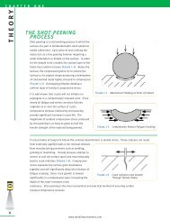
HISTORICAL BACKGROUND<br />
<strong>Shot</strong> <strong>Peening</strong> was first used, in a production application, to extend<br />
the life <strong>of</strong> the valve springs for the Buick and Cadillac engines<br />
<strong>of</strong> the early 1930s (Ref. 1). The process was discovered accidentally<br />
and, although the benefits were soon recognized, it was several years<br />
before a mechanism was proposed and even longer before is was generally<br />
accepted. It was recognized, at the time, that fatigue cracks initiated<br />
under repeated tensile loads. John Almen postulated that shot<br />
peening produced the increases in fatigue life from the introduction,<br />
<strong>of</strong> a high residual compressive stress, which remained just below<br />
the surface <strong>of</strong> the part (Fig. 1, Ref. 2).<br />
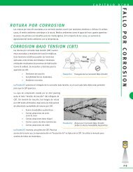
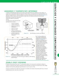
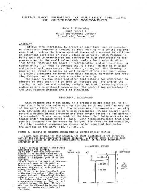
FIGURE 1. EXAMPLE OF RESIDUAL STRESS PROFILE CREATED BY SHOT PEENING.<br />
In most applications for shot peening, the benefit obtained is the direct result<br />
<strong>of</strong> the residual compressive stress produced. A typical pr<strong>of</strong>ile <strong>of</strong> residual<br />
compressive stress as it changes with depth is shown. It has four important<br />
characteristics:<br />
1) SS - Surface stress - The stress<br />
measured at the surface. (+)<br />
2) CS max - Maximum Compressive TENSION +100<br />
<strong>Stress</strong> - The maximum value <strong>of</strong> the t<br />
% ULTIMATE TENSILE STRENGTH<br />
(-)<br />
+50 0 -100 COMPRESSION<br />
I I I I 0<br />
compressive stress induced, which ~----~-,---+------~----i<br />
normally is highest just below the<br />
~ -ss-1),<br />
surface.<br />
.L,<br />
2<br />
3) d - Depth - The depth <strong>of</strong> the compressive<br />
stress is the point at<br />
~S~<br />
4<br />
which the compressive stress crosses<br />
over the neutral axis and be-<br />
6<br />
comes tensile.<br />
...,.- f-- TS MAX<br />
4). TS max - Maximum Tensile <strong>Stress</strong><br />
- The maximum value <strong>of</strong> the tensile<br />
8<br />
stress induced. The <strong>of</strong>fsetting tensile<br />
stress in the core <strong>of</strong> the material<br />
balances the surface layer <strong>of</strong><br />
compressive stress so that the part<br />
12<br />
remains in equilibrium. TS max<br />
must not be allowed to become large<br />
enough to create early internal<br />
fa; lures.<br />
0'0<br />
DEPTH<br />
BELOW<br />
SURFACE
Any applied tensile loads, affirmed Almen, would have to<br />
overcome this residual compression before a crack could start. Furthermore,<br />
Almen claimed that many parts (springs, for instance, from<br />
the coiling operation) had in them, from manufacturing, residual tensile<br />
stresses, that when added upon by the tensile loads, would further<br />
contribute to the part's early failure. <strong>Shot</strong> <strong>Peening</strong>, he said,<br />
reversed the surface residual stress from tension to compression,<br />
accounting for the very great improvements in fatigue life that are<br />
typical <strong>of</strong> the process. The academic community was almost totally<br />
opposed to John Almen's theories since, at the time, the presence <strong>of</strong><br />
residual stresses in metals was not recognized in engineering calculations.<br />
The advent <strong>of</strong> Fracture Mechanics eventually vindicated<br />
Almen's position. Today, we not only recognize residual (or self)<br />
stresses; we are able to measure them with a considerable degree <strong>of</strong><br />
consistency, primarily by x-ray diffraction.<br />
Consideration Of Residual <strong>Stress</strong>es<br />
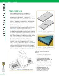
If the part is dimensionally correct, are residual stresses all<br />
that important, in a fatigue application? A very current case is an<br />
excellent illustration. A group <strong>of</strong> engineers are developing a torsion<br />
bar for a space application (the exact nature is "classified").<br />
They carefully ground the test torsion bars to produce the final pr<strong>of</strong>ile<br />
and a smooth surface. The unpeened torsion bars, at the applied<br />
load level, averaged close to a million cycles to failure and the<br />
stress analyst in the group figured from this information, that shot<br />
peening would about double the life <strong>of</strong> the bars, to two million<br />
cycles: sufficient for the application. To his surprise, the first<br />
(and only) <strong>Shot</strong> Peened torsion bar that they tested ran for 166 million<br />
cycles when the test was discontinued.<br />
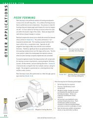
FIGURE 2. RESIDUAL STRESS IN 4340 STEEL (HRC 50) AFTER SURFACE GRINDING.<br />
Graph shows the stress distribution<br />
created by different grinding techniques<br />
- conventional, abusive and<br />
gentle. It is quite evident that<br />
conventional grlnding and abusive<br />
grinding can generate high magnitudes<br />
<strong>of</strong> resiaual tensile stress at<br />
or near the surface <strong>of</strong> the Rarts.<br />
This tensile stress will, <strong>of</strong><br />
course, dramatically affect fatigue<br />
.resistance.<br />
100<br />
80<br />
60<br />
40<br />
~ -20<br />
Vi<br />
en<br />
UJ<br />
a:<br />
a.<br />
1§ -4<br />
o<br />
0<br />
I<br />
/ \<br />
I \<br />
I \<br />
I \<br />
\<br />
:\<br />
\ \<br />
!\ \ \<br />
I "< CONVENTIONAL \. Y ABUSIVE<br />
I<br />
\~<br />
,V<br />
i--.<br />
"
<strong>Shot</strong> Peened, the surface residual stresses were reversed, from close<br />
to the yield strength in tension to close to the yield strength in<br />
compression or a delta, in this case, <strong>of</strong> over 300 KSI. The <strong>Shot</strong> <strong>Peening</strong><br />
actually raised the endurance limit <strong>of</strong> the torsion bars well over<br />
the stress level applied in the testing, contributing to virtually infinite<br />
life. Not all applications <strong>of</strong> <strong>Shot</strong> <strong>Peening</strong> are so dramatic<br />
but this is a good reminder that residual stresses, detrimental or<br />
beneficial, should not be ignored.<br />
Realizing that the Purdue Conference is directed almost exclusively<br />
at engineers involved with small compressors for refrigeration and<br />
air conditioning, we thought it would be useful to review, quite<br />
briefly, some <strong>of</strong> the applications <strong>of</strong> the <strong>Shot</strong> <strong>Peening</strong> process in the<br />
very large or very different compressors that are found in other industries,<br />
since much can be learned from them. Then, we want to be<br />
more specific in discussing the benefits <strong>of</strong> <strong>Shot</strong> <strong>Peening</strong> for valve<br />
reeds and rings since our unique success in this area has propelled<br />
Metal Improvement Company to become one <strong>of</strong> the leading manufactures<br />
<strong>of</strong> these very critical components.<br />
SHOT PEENING FOR INDUSTRIAL AND AIRCRAFT COMPRESSORS<br />
Reciprocating <strong>Compressor</strong>s<br />
1.Crankshafts are most commonly peened in the fillets <strong>of</strong> the<br />
pins and mains to produce increases in fatigue strength <strong>of</strong> up to 30%.<br />
Crankshafts have also been peened in the oil holes and keyways (Fig.<br />
3, Ref. 4).<br />
FIGURE 3. INCREASE IN FATIGUE STRENGTH OF SHOT PEENED CRANKSHAFTS.<br />
The most highly stressed area <strong>of</strong> a crankshaft is the crank pin bearing fillet.<br />
The high stress point is the bottom side <strong>of</strong> the fillet when the pin is in the top<br />
dead center position during the firing cycle. It is common for cracks to initiate<br />
in this pin fillet and propagate through the web <strong>of</strong> the crankshaft to the adjacent<br />
main bearing fillet, causing fatigue failure. All sizes <strong>of</strong> crankshafts respond<br />
well to shot peening, from small high speed shafts with journai bearing diameters<br />
<strong>of</strong> 1" to large slow speed shaft~ having journal bearing diameters <strong>of</strong> 6" and more.<br />
Experlence has shown the process to be effective on forged steel, cast steel, nodu-<br />
1ar iron, and austempered ducti 1e iron. LUBRICATING HOLE<br />
~ /<br />
,Y/<br />
--.v<br />
",I<br />
~I<br />
t;i1u<br />
;tIS<br />
~Ib<br />
~17, WEB<br />
I<br />
2.Connecting Rods are usually peened prior to machining, to prevent<br />
fatigue failures in the I-beam section but some large ones are<br />
also peened in the oil holes and in the fillets by the bolts. Fr~tting<br />
fatigue is prevented by peening the serrations between the rod<br />
and the cap, the bearing surfaces, and the bolt holes.<br />
3. Connecting Rod Bolts are shot peened for axial fatigue in<br />
the shank to head fillet and for fretting fatigue in the shank itself.<br />
Sometimes, the thread roots are peened, which can impart to a<br />
cut thread almost the same fatigue strength as a rolled thread.<br />
4. Tie-Rod Bolts are used in very large compressors to hold the<br />
assembly together or are used just around the cylinder heads. These<br />
bolts are peened for the same reasons as the connecting rod bolts described<br />
above.<br />
5. Tail Rod Cylinders are peened at the intersections <strong>of</strong> crossbores<br />
to prevent crack initiation.<br />
6. Hyper Cups are used to hold the seal around the push rods <strong>of</strong><br />
very high pressure (approaching 50,000 PSI) compressors. The <strong>Shot</strong><br />
<strong>Peening</strong> retards failures from bending and fretting fatigue.<br />
7. Ring and Strip <strong>Valve</strong>s are edge finished and peened for very
Centrifugal <strong>Compressor</strong>s<br />
Impellers have been <strong>Shot</strong> Peened that range in size from less than<br />
2 inches in diameter for a space application to 48 inches for process<br />
air. Turbochargers fall under this classification and many are shot<br />
peened against blade failure. One unique application involved thermal<br />
cracking at some locating serrations on the back face <strong>of</strong> aluminum<br />
impellers for locomotive diesel turbochargers. Of concern was the<br />
heat that might relieve the compressive stresses form <strong>Shot</strong> <strong>Peening</strong>.<br />
However, peening solved the problem, using glass beads to avoid ferrous<br />
contamination <strong>of</strong> the aluminum.<br />
Most <strong>of</strong> the smaller turbines employed in aircraft, sometimes for<br />
propulsion, but most <strong>of</strong>ten as auxiliary power units, air starters,<br />
etc., use <strong>Shot</strong> Peened impellers, as do the engines for the Cruise Missile.<br />
Significant weight reductions are possible by including the<br />
benefits <strong>of</strong> <strong>Shot</strong> <strong>Peening</strong> in the design calculations. Materials for<br />
impellers, incidentally, may be sand cast iron or aluminum, welded<br />
steel, forged aluminum or titanium; even investment cast superalloys:<br />
all respond well to <strong>Shot</strong> <strong>Peening</strong>.<br />
Axial <strong>Compressor</strong>s<br />
Many are used in stationary applications (a good one is for making<br />
snow on the ski slopes), but most axial compressors are used in<br />
combination with a gas turbine to form a jet engine and provide propulsion<br />
for planes, boats and trains, and some experimental trucks.<br />
Because <strong>of</strong> the extreme centrifugal, axial and vibrational forces acting<br />
on the rotating components, all shafts, disks and blades are typically<br />
<strong>Shot</strong> Peened against bending and fretting fatigue. In fact,<br />
there are very few components <strong>of</strong> a high performance jet engine that<br />
are not peened, both during original manufacture and again at periodic<br />
overhaul intervals, and include less obvious components such as<br />
gears and fuel lines.<br />
Diaphragm <strong>Compressor</strong>s<br />
Diaphragm compressors are quite uncommon and are used in applications<br />
where absolutely no contamination (from lubricating oils, for<br />
instance) <strong>of</strong> the compressed gas is permitted. The critical component<br />
is a large (up to 30 inches diameter by 0.030 inch thick) stainless<br />
steel diaphragm that is clamped around the edges in the compressor<br />
head. Because the diaphragm moves up and down under hydraulic pressure,<br />
cracks initiate just inside <strong>of</strong> the bolt hole ring. Typically,<br />
a chemical company, compressj~g Freon, used to replace these diaphragms<br />
every 16 hours <strong>of</strong> service. <strong>Peening</strong> the diaphragm with glass<br />
beads (on stainless steel) extended the service life to 6 months.<br />
The difficulty here is to peen the large but very thin diaphragm and<br />
still maintain flatness: exactly the same problem that is encountered<br />
in peening the small valve reeds with which you are all familiar.<br />
COMPRESSOR VALVE COMPONENTS<br />
To Quote D. N. Lal, Research Engineer at the Carrier Corporation:<br />
"The valve, suction or discharge, is one <strong>of</strong> the most critical<br />
components <strong>of</strong> a compressor. A flapper valve is required to have high<br />
flexibility to allow unrestricted fluid passage through the ports-for<br />
achieving high efficiency and capacity <strong>of</strong> the compressor, but at the<br />
same time it is also expected to have enough stiffness to return back<br />
in time to seal the ports completely. The motion subjects the valve<br />
to severe cyclic stresses and strains. To make the situation worse,<br />
most <strong>of</strong> the valves have irregular geometry as unavoidable design re-<br />
Quirements. This increases the possibility <strong>of</strong> localized stress concentration<br />
and premature failure by fatigue" (Ref. 5). Few would<br />
dispute Lal's statement but it leaves the designer <strong>of</strong> a compressor<br />
with having to make a serious compromise between the efficiency <strong>of</strong><br />
the compressor and the life <strong>of</strong> the valve. The more the flapper reed<br />
flexes, the more passage <strong>of</strong> fluid it will permit but the shorter will<br />
be the number <strong>of</strong> flexures the flapper will sustain before breaking.<br />
It is incumbent on the designer to seek a reed that will allow the<br />
maximum passage <strong>of</strong> fluid without breakage during the expected life <strong>of</strong><br />
the compressor at, let's not forget, a cost that is within budget.
" .<br />
The geometry <strong>of</strong> the reed is usually the first consideration and<br />
one over which the manufacturer <strong>of</strong> the reed has little control. Actually,<br />
the designers are much better served if they include the manufacturer<br />
at an early stage <strong>of</strong> the design. A manufacturer <strong>of</strong> reeds<br />
should not just be able to stamp out metal shapes: he must thoroughly<br />
understand all the factors that influence the life expectancy <strong>of</strong> a<br />
valve. For instance, the diameter <strong>of</strong> a mounting hole or the width <strong>of</strong><br />
a slot, within obvious limits, may have little influence on the efficiency<br />
<strong>of</strong> a reed but they can create difficulties for the reed maker<br />
that will impact both on the life and the cost <strong>of</strong> a reed. The reed<br />
maker must have a complete knowledge <strong>of</strong> materials; stresses (applied<br />
and residual; beneficial and detrimental); how life is affected by<br />
edge geometry, surface conditions, heat and corrosion; and the influence<br />
<strong>of</strong> bending, torsion and impact loads. Because his speciality is<br />
valves (and not compressors) the reed manufacturer can be <strong>of</strong> great<br />
value to the designer.<br />
The ideal valve reed would open fully and close totally in zero<br />
time: and last forever. We certainly are not there yet but an evolving<br />
technology, based on a more complete understanding <strong>of</strong> the many<br />
phenomena involved, is taking the best reed makers ever closer. We<br />
know that there are at least five areas that must be given attention:<br />
1. Choice <strong>of</strong> material, 2. stamped edges, 3. Removal <strong>of</strong> defects<br />
and detrimental stresses, 4. Edge rounding, 5. Depth and magnitude <strong>of</strong><br />
beneficial stress. We will address each <strong>of</strong> these items individually<br />
but it must be remembered that all are very much interrelated. For<br />
instance, maximizing #5, in theory would allow the use <strong>of</strong> thinner<br />
steel (#1) so that the reed would flex more and faster but maintaining<br />
flatness could then become a difficulty that would compromise the<br />
reed's ability to close totally. Overcoming this difficulty is the<br />
province <strong>of</strong> a good reed maker and much has been done in this area.<br />
Pursuing all <strong>of</strong> the above items to the maximum <strong>of</strong> current technology<br />
will produce a reed closest to the ideal. The extent <strong>of</strong> this pursuit<br />
is governed by the cost considerations <strong>of</strong> the application and the<br />
degree <strong>of</strong> efficiency that the designer wishes to obtain for the compressor.<br />
Designers need to be aware <strong>of</strong> the options available to them.<br />
Choice <strong>of</strong> Material<br />
There is much information published by the suppliers <strong>of</strong> valve<br />
steels and it is not our province to review it in detail. High carbon<br />
strip is the choice for thin reeds and is supplied and stamped in<br />
the pre-hardened condition .. Nickel-alloyed steel is usually used for<br />
thicker valves and hardened after stamping. Stainless is preferred<br />
for applications where corrosion can be a problem (Fig. 4, Ref. 6),<br />
such as in the presence <strong>of</strong> air, water or steam, dilute organic acids<br />
and sulphurous fumes. A corrosive environment will always lower fatigue<br />
properties, even in stainless steels, but the effect can be<br />
largely over come by the introduction <strong>of</strong> high residual compressive<br />
stresses.<br />
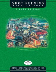
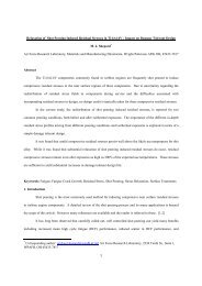
FIGURE 4. STRESS CORROSION CRACKING.<br />
Effect <strong>of</strong> shot peening with 40-80 m glass shot on the times to failure to<br />
type 304 and 347 stainless steels in a boiling 42% magnesium chloride solution~<br />
280r-----------------------------------------~<br />
ca. 240<br />
:E<br />
.n-<br />
Ul<br />
LrJ<br />
0:: 200<br />
~(/')<br />
0<br />
LrJ<br />
.J 160<br />
a.<br />
a.<br />
~<br />
120<br />
I<br />
10 100<br />
TIME TO FAILURE. HOURS<br />
0347<br />
® 304<br />
---<br />
not shot peened<br />
700
Stamped Edges<br />
A fatigue failure will always nucleate at the point <strong>of</strong> greatest<br />
stress concentration: sometimes at an inclusion in the steel, but in<br />
the case <strong>of</strong> valve reeds, almost always at a surface defect created by<br />
the stamping operation (Ref. 7). All subsequent operations, i.e.,<br />
edge rounding, removal <strong>of</strong> defects and introduction <strong>of</strong> beneficial<br />
stresses, are all performed primarily to remove or <strong>of</strong>fset these surface<br />
defects from stamping. The technology <strong>of</strong> producing good reeds<br />
is totally tied to the technique <strong>of</strong> producing stamped edges that are<br />
as free from defects as possible. The importance <strong>of</strong> this will become<br />
more apparent as we look at the subsequent operations.<br />
Removal <strong>of</strong> Defects and Detrimental <strong>Stress</strong>es<br />
There are a variety <strong>of</strong> processes available to the reed maker to,<br />
essentially, wear away the stamped edges and smooth out the stress<br />
concentrating defects. All are very time-consuming (and cost raising)<br />
and have limitations, especially from reed geometry. For instance,<br />
rough edges <strong>of</strong> narrow slots and small holes are very difficult<br />
to smooth out without loosing dimensions on the more exposed edges.<br />
Starting with stamped edges that are essentially free <strong>of</strong> defects is<br />
paramount here. Also, the stamping operation introduces residual<br />
tensile stresses at the edges <strong>of</strong> the reed. A good edge finishing<br />
process, such as STRESS-LITE, (Fig. 5, Ref. 8) will reverse these<br />
detrimental residual tensile stresses into beneficial compressive<br />
stresses but, again, starting with a near perfect stamping makes the<br />
stress reversal process not only more effective but, in some cases,<br />
even possible.<br />
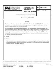
FIGURE 5. LCF OF SUCTION VALVE, IN THREE CONDITIONS.<br />
The bar chart shows the,performance <strong>of</strong> a particular valve for which filed failure<br />
data have been statistlcally related to a low cycle/high stress condition<br />
ther~by p~rmitting ~ccelerated life testing. This suction valve is used in an air<br />
condltlonlng hermetlc compressor.<br />
AS STAMPED<br />
STRESS-LITE<br />
STRESS-LITE &<br />
SHOTPEEN<br />
I I<br />
I I<br />
I I<br />
I I<br />
CYCLES 0 45M 60M 192M<br />
Edge Rounding<br />
Bending and torsional stresses are concentrated not only by notches<br />
(surface defects) but also at sharp outside corners. Therefore,<br />
even if we had a theoretically perfect stamped edge, it would still<br />
be necessary to use processes that will round the edges and distribute<br />
the applied stresses over a greater area. Here, again, the quality<br />
<strong>of</strong> the stamped edge is key: to the degree that the as-stamped<br />
edge is smooth, less edge-rounding is necessary. Too much edge finishing<br />
can produce a taper in the thickness <strong>of</strong> the reed on the sealing<br />
surface so that the reed will not close <strong>of</strong>f the port. This may<br />
be difficult or even impossible to prevent if large defects from<br />
stamping must be removed in narrow slots to avoid fatigue.<br />
Depth and Magnitude <strong>of</strong> Compressive <strong>Stress</strong>es<br />
Compressive stresses can be introduced by the correct edgefinishing<br />
process. They will be very shallow and <strong>of</strong> relatively low<br />
magnitude but, in many cases, are sufficient for the application,<br />
particularly if the stamped edges are near-perfect.<br />
<strong>Shot</strong> peening will, as we have seen in the earlier sections <strong>of</strong><br />
this paper, introduce much deeper residual compressive stresses and
<strong>of</strong> a magnitude approaching the yield strength <strong>of</strong> the steel. It does<br />
so by" indenting the surface so that the compressive stress is created<br />
in the subsurface layer that can be thought <strong>of</strong> as trying to push the<br />
indentation back out again. The magnitude <strong>of</strong> this compressive<br />
stress, then becomes a function <strong>of</strong> the yield strength <strong>of</strong> the material,<br />
as long as the surface is totally indented. As far as fatigue is<br />
concerned, the higher the magnitude <strong>of</strong> residual compression, the higher<br />
the fatigue strength and the longer the life <strong>of</strong> the reed. However,<br />
surface defects or discontinues always have a debiting effect on<br />
fatigue life, particularly if any are deeper than the layer <strong>of</strong> residual<br />
compressive stress (Fig. 6).<br />
FIGURE 6. STRESS-LITEAND SHOT PEENING.<br />
STRESS-LITE is a proprietaryprocess developedto control edge radius, improve<br />
surface finish and to induce a high magnitude<strong>of</strong> residual compressivestress for increased<br />
fatigue life. The illustrationis <strong>of</strong> a 2-cycle outboard engine reed<br />
blanked out <strong>of</strong> stainless steel, which has a drawing requirementfor a minimum <strong>of</strong><br />
110 000 psi at the tips and 80,000 psi compressionon the balance <strong>of</strong> the reed.<br />
STR~SS-LITE is used to process the entire reed to yield residual stresses as high<br />
as 97,000 to 99,000 psi. Addition <strong>of</strong> <strong>Shot</strong> <strong>Peening</strong> to the tips increasesthe surface<br />
residual compressivestress to as much as 132,000 psi.<br />
STRESS-LITE<br />
+ SHOT PEEN, --}<br />
110,000 psi min.<br />
o o o o o<br />
STRESS-LITE<br />
(-- only<br />
80,060 psi min.<br />
On a relatively thick part, say a quarter inch (6mm) or more, it<br />
is quite easy to peen to a depth <strong>of</strong> 0.010 inch (0.25mm) to get below<br />
surface discontinues. <strong>Peening</strong> very thin valve reeds is an entirely<br />
different proposition and there are two interconnected concerns: distortion<br />
and internal stresses. Metal Improvement Company actually<br />
uses a controlled distortion (Peen Forming) to produce the aerodynamic<br />
curvatures on aircraft wing skins that can be as much as an inch<br />
(25mm) thick and 110 feet (34 meters) long (Ref. 9). Effectively<br />
<strong>Shot</strong> <strong>Peening</strong> reeds that may be only 0.06 inch (0.4mm) thick while<br />
holding acceptable flatness tolerances, requires unusual techniques.<br />
Beyond the distortion, though, consideration must also be given to internal<br />
tensile stresses. Putting the surface into compression always<br />
produces a corresponding tensile stress in the core <strong>of</strong> the metal. If<br />
the depth <strong>of</strong> compression is too deep relative to the thickness, the<br />
core tensile stresses can become high enough to cause subsurface fatigue<br />
failures and shorten valve life (also see Fig. 1). Critical<br />
control <strong>of</strong> the depth <strong>of</strong> compression can be exercised by intelligent<br />
use <strong>of</strong> the Almen Intensity System (Ref. 10). Peenscan R , a fluorescent<br />
tracer, is used to determine when 100% coverage has been reached<br />
(Ref. 11). These and other tools and techniques are applied today to<br />
gain great improvements and repeatability in the fatigue life <strong>of</strong><br />
modern valve reeds.<br />
CONCLUSION<br />
Controlled <strong>Shot</strong> <strong>Peening</strong> is used very effectively in the manufacture<br />
<strong>of</strong> many components <strong>of</strong> both large and small compressors. Very<br />
significant increases in life <strong>of</strong> valve reeds and rings can be<br />
achieved with <strong>Shot</strong> <strong>Peening</strong> but it must be used in combination with<br />
advanced techniques for stamping and edge finishing, as well as<br />
correct choice <strong>of</strong> material.
References<br />
1. "Impact", Fall 1989, Metal Improvement Company, Bloomfield, Connecticut.<br />
2. Fuchs, H. 0., "<strong>Shot</strong> <strong>Peening</strong> <strong>Stress</strong> Pr<strong>of</strong>iles", Metal Improvement<br />
Company, Bloomfield, CT.<br />
3. Koster, W. P., et. al., "Surface Integrity <strong>of</strong> Machined Structural<br />
<strong>Components</strong>", Technical Report AFML-TR-70-11, March 1970.<br />
4. Sandberg, E., Det Norske Veritas, Letter to Metal Improvement Company,<br />
September 1, 1983.<br />
5. Lal, D. N., "The Use <strong>of</strong> Finite Element Method for <strong>Stress</strong> Analysis<br />
<strong>of</strong> <strong>Compressor</strong> <strong>Valve</strong>s", Proceedings <strong>of</strong> the 1978 Purdue <strong>Compressor</strong> Technology<br />
Conference, Purdue University, West Lafayette, Indiana.<br />
6. Heckert, R., Mogul, J., "The App lication <strong>of</strong> Controlled <strong>Shot</strong> <strong>Peening</strong><br />
for the Prevention <strong>of</strong> <strong>Stress</strong> Corrosion Cracking", Metal Improvement<br />
Company.<br />
7. Dusil, R., "On Blanking, Tumbling and <strong>Shot</strong>-<strong>Peening</strong> <strong>of</strong> <strong>Compressor</strong><br />
<strong>Valve</strong>s", Proceedings <strong>of</strong> the 1978 Purdue <strong>Compressor</strong> Technology Conference,<br />
Purdue University, West Lafayette, Indiana.<br />
8. Carlyle <strong>Compressor</strong> Company, Syracuse, New York.<br />
9. "<strong>Shot</strong> <strong>Peening</strong> Applications", Pg. 45, Metal Improvement Company,<br />
Bloomfield, CT.<br />
10. "<strong>Shot</strong> <strong>Peening</strong> Applications", Pg. 61, Metal Improvement Company,<br />
Bloomfield, CT.<br />
11. "<strong>Shot</strong> Peen ing App 1 icat ions", Pg. 64, Meta 1 Improvement Company,<br />
Bloomfield, CT.<br />
Metal Improvement Company<br />
<strong>Valve</strong> Division<br />
98 Filley Street<br />
Bloomfield, CT 06002 USA<br />
Te 1. (203) 243-2220<br />
FAX. (203) 242-7292