AMS-S-13165 - Metal Improvement Company
AMS-S-13165 - Metal Improvement Company
AMS-S-13165 - Metal Improvement Company

Create successful ePaper yourself
Turn your PDF publications into a flip-book with our unique Google optimized e-Paper software.
400 Commonwealth Drive, Warrendale, PA 15096-0001<br />
AEROSPACE<br />
MATERIAL<br />
SPECIFICATION<br />
Submitted for recognition as an American National Standard<br />
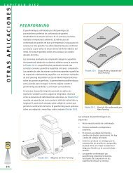
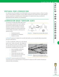
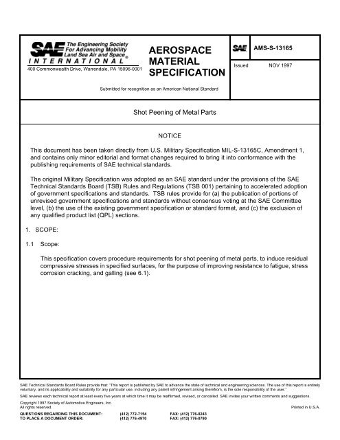
Shot Peening of <strong>Metal</strong> Parts<br />
NOTICE<br />
SAE Technical Standards Board Rules provide that: “This report is published by SAE to advance the state of technical and engineering sciences. The use of this report is entirely<br />
voluntary, and its applicability and suitability for any particular use, including any patent infringement arising therefrom, is the sole responsibility of the user.”<br />
SAE reviews each technical report at least every five years at which time it may be reaffirmed, revised, or cancelled. SAE invites your written comments and suggestions.<br />
Copyright 1997 Society of Automotive Engineers, Inc.<br />
All rights reserved. Printed in U.S.A.<br />
QUESTIONS REGARDING THIS DOCUMENT: (412) 772-7154 FAX: (412) 776-0243<br />
TO PLACE A DOCUMENT ORDER: (412) 776-4970 FAX: (412) 776-0790<br />
<strong>AMS</strong>-S-<strong>13165</strong><br />
Issued NOV 1997<br />
This document has been taken directly from U.S. Military Specification MIL-S-<strong>13165</strong>C, Amendment 1,<br />
and contains only minor editorial and format changes required to bring it into conformance with the<br />
publishing requirements of SAE technical standards.<br />
The original Military Specification was adopted as an SAE standard under the provisions of the SAE<br />
Technical Standards Board (TSB) Rules and Regulations (TSB 001) pertaining to accelerated adoption<br />
of government specifications and standards. TSB rules provide for (a) the publication of portions of<br />
unrevised government specifications and standards without consensus voting at the SAE Committee<br />
level, (b) the use of the existing government specification or standard format, and (c) the exclusion of<br />
any qualified product list (QPL) sections.<br />
1. SCOPE:<br />
1.1 Scope:<br />
This specification covers procedure requirements for shot peening of metal parts, to induce residual<br />
compressive stresses in specified surfaces, for the purpose of improving resistance to fatigue, stress<br />
corrosion cracking, and galling (see 6.1).
<strong>AMS</strong>-S-<strong>13165</strong> SAE <strong>AMS</strong>-S-<strong>13165</strong><br />
2. APPLICABLE DOCUMENTS:<br />
The following publications, of the issues in effect on date of invitation for bids or request for proposal,<br />
form a part of this specification to the extent specified herein.<br />
2.1 U.S. Government Publications:<br />
Available from DODSSP, Subscription Services Desk, Building 4D, 700 Robbins Avenue,<br />
Philadelphia, PA 19111-5094.<br />
MIL-S-851 Steel Grit, Shot, and Cut Wire Shot; and Iron Grit and Shot-Blast Cleaning and<br />
Peening<br />
MIL-S-5002 Surface Treatments and Inorganic Coatings for <strong>Metal</strong> Surfaces of Weapon<br />
Systems<br />
MIL-G-9954 Glass Beads, For Cleaning and Peening<br />
MIL-STD-45662 Calibration Systems Requirements<br />
RR-S-366 Sieves, Test<br />
2.2 SAE Publications:<br />
Available from SAE, 400 Commonwealth Drive, Warrendale, PA 15096-0001.<br />
J441 Cut Wire Shot<br />
J1830 Ceramic Shot for Peening<br />
3. REQUIREMENTS:<br />
3.1 Shot:<br />
3.1.1 Material: The shot used shall be made from cast iron, cast steel, cut steel wire (or stainless cut<br />
wire), glass, or ceramic as specified or approved. The hardness shall be determined by any of the<br />
various methods applicable to small sections at loads determined to provide a reliable conversion<br />
to Rockwell C. Steel and iron shot shall conform to MIL-S-851. For steel parts over 200,000 psi<br />
tensile strength, use hard steel shot in the range 55-65 HRC or ceramic shot, hardness<br />
comparable to 57-63 HRC, unless otherwise specified (see 6.14). Stainless steel cut wire shot,<br />
type 302 or 304 (condition B spring temper), and carbon steel cut wire shot shall conform to<br />
SAE J441. Glass beads shall conform to MIL-G-9954 except for sieve analysis. Ceramic beads<br />
shall meet the requirements of SAE J1830.<br />
3.1.2 Size: Unless otherwise specified, the size of shot charged into the machine, whether new shot,<br />
used shot, or reclassified shot, shall be at the option of the contractor and shall be as specified in<br />
table II (cast sizes), table III (cut wire sizes), table IV (glass bead sizes) or table V (ceramic bead<br />
sizes).<br />
- 2 -
<strong>AMS</strong>-S-<strong>13165</strong> SAE <strong>AMS</strong>-S-<strong>13165</strong><br />
3.1.3 Shape: The shot or beads shall be free from sharp edges and inspected for deformed shapes or<br />
broken shapes when examined per 4.3.1, 4.3.3, and figure 7. Cut wire shot, if used, shall be<br />
preused or burnished to eliminate sharp edges (see 6.17.1). A given sample size shall contain no<br />
more than the number of unacceptable deformed shapes as shown in figure 7, and defined in<br />
table I below (see 3.3.9).<br />
Cast<br />
Shot<br />
Sizes<br />
TABLE I. Maximum allowable number of unacceptable deformed shapes<br />
Cut<br />
Wire<br />
Sizes<br />
Glass<br />
Bead<br />
Sizes<br />
(Inches)<br />
Ceramic<br />
Bead<br />
Sizes<br />
(Inches)<br />
- 3 -<br />
Sample<br />
Size<br />
(Inches)<br />
*Maximum Allowable<br />
Number of<br />
Unacceptable<br />
Deformed Shapes<br />
930 — .132-.094 — 1 x 1 8<br />
780 — .111-.079 — 1 x 1 11<br />
660 CW-62 .094-.066 — 1 x 1 16<br />
550 CW-54 .079-.056 — 1 x 1 22<br />
460 CW-47 .066-.047 — 1 x 1 32<br />
390 CW-41 .056-.039 — 1 x 1 45<br />
330 CW-35 .047-.0331 0.046 1/2 x 1/2 16<br />
— CW-32 — — 1/2 x 1/2 18<br />
280 CW-28 .039-.0278 — 1/2 x 1/2 23<br />
230 CW-23 .0331-.0234 0.033 1/2 x 1/2 32<br />
190 CW-20 .0278-.0197 — 1/2 x 1/2 45<br />
170 — .0234-.0165 0.024 1/4 x 1/4 16<br />
130 — .0197-.0139 — 1/4 x 1/4 23<br />
110 — .0165-.0117 0.017 1/4 x 1/4 32<br />
70 — .0139-.0098 — 1/4 x 1/4 45<br />
— — .0117-.0083 0.012 1/8 x 1/8 16<br />
— — .0098-.0070 — 1/8 x 1/8 22<br />
— — .0083-.0059 0.008 1/8 x 1/8 31<br />
*These numbers are approximations based on approximately 10% of the actual<br />
particle count in the given sample size.
<strong>AMS</strong>-S-<strong>13165</strong> SAE <strong>AMS</strong>-S-<strong>13165</strong><br />
3.2 Equipment:<br />
3.2.1 Automatic shot peening: The machine used for shot peening shall provide means for propelling<br />
shot by air pressure or centrifugal force against the work, and mechanical means for moving the<br />
work through the shot stream or moving the shot stream through the work in either translation or<br />
rotation, or both, as required. The machine shall be capable of reproducing consistently the shot<br />
peening intensities required. Except for wet glass bead peening (see 3.3.9), the equipment shall<br />
continuously remove broken or defective shot so that this shot will not be used for peening.<br />
3.2.2 Computer-controlled shot peening: When specified in the contract or purchase order (see 6.2 and<br />
6.8), the machine used for shot peening shall be as in 3.2.1 and also shall be equipped with<br />
computer aided monitoring equipment. This equipment shall continuously monitor critical process<br />
parameters through interaction with a sensing system. The media shall be metered to each nozzle<br />
and wheel with the desired shot flow. Process parameters shall be as specified by the procuring<br />
activity (see 6.9). The machine shall be stopped immediately and corrective action shall be taken<br />
when any of the established process limits is violated. The electronic system used for monitoring<br />
and controlling shot peening shall include a data recording device which will mark (plot) process<br />
interruptions or inconsistencies, and shall be maintained for the purpose of providing a hard copy<br />
record.<br />
3.3 Procedure:<br />
3.3.1 Dimensions and condition of parts: Areas of parts to be shot peened shall be within dimensional<br />
and surface finish requirements before peening. All heat treatment, machining and grinding shall<br />
be completed before shot peening. All fillets shall be formed, all burrs shall be removed, and all<br />
sharp edges and corners to be peened shall be provided with sufficient radii to result in complete<br />
coverage without any distortion prior to peening (see 6.15).<br />
3.3.2 Precleaning: Except as otherwise specified or permitted, all areas to be peened shall be cleaned in<br />
accordance with MIL-S-5002. Procedures for stripping coatings shall be as specified or approved<br />
in the contract or on the applicable drawings.<br />
3.3.3 Masking: Areas of the part or work piece and the dimensional tolerances of these areas which are<br />
designated in the contract or applicable drawing to be free from any shot peening marks shall be<br />
suitably masked or otherwise handled to protect such surfaces from the shot stream or subsequent<br />
damage. Areas not requiring peening and not required to be masked shall be considered optional.<br />
3.3.4 Magnetic particle or penetrant inspection: Except as otherwise specified, when magnetic particle<br />
or dye penetrant inspection is required, parts shall be subjected to such inspection before peening.<br />
3.3.5 Loading: Unless otherwise specified or permitted, parts shall be free from externally applied loads<br />
or forces during shot peening.<br />
- 4 -
<strong>AMS</strong>-S-<strong>13165</strong> SAE <strong>AMS</strong>-S-<strong>13165</strong><br />
3.3.6 Peening intensity: Unless otherwise specified on the drawing or in the contract, the intensity value<br />
of the shot stream used on the part shall be as specified in table VI for the thickness of the material<br />
being peened. If only a minimum intensity is specified, the variation from the specified minimum<br />
intensity shall be -0, +30% rounded to the nearest unit, but in no case less than 3 intensity units<br />
(A, C, or N) unless otherwise specified. For example, a specified peening intensity of 6A would<br />
denote an arc height of 0.006-0.009 inches on the “A” specimen. Shot peening of parts shall be<br />
accomplished using the same parameters (time, distance, blast pressure, angle of incidence, etc.)<br />
as used on the test strip.<br />
3.3.7 Coverage: Areas of parts shot peened in compliance with design requirements shall be peened to<br />
complete visual coverage (see 4.4.1 and 6.11). When a surface on which peening is required is<br />
obstructed and it is impossible to obtain complete visual coverage by direct impact, coverage by<br />
reflected shot is allowed. Full coverage will not be required if the part is peened only for forming or<br />
straightening. Critical applications shall be as specified by the procuring activity (see 4.2 and 6.11).<br />
3.3.7.1 Boundary variation: Unless otherwise specified, the variation in boundaries of areas to be<br />
peened, when limited, shall be -0 to +1/8 inch.<br />
3.3.7.2 Fillets and shielded areas: Unless otherwise specified, the nominal size of shot used on fillet<br />
surfaces shall not be greater than one-half the fillet radius. For slots or other apertures, through<br />
which shot must pass to peen shielded critical areas, the nominal shot diameter shall not be<br />
greater than 1/4 the diameter or width of such aperture.<br />
3.3.8 Minimum shot size for peening materials: Except as otherwise specified or permitted, or in cases<br />
such as when shielded areas are involved, materials shall not be peened with shot smaller than the<br />
following for the intensities given:<br />
Intensity Peening Media<br />
.012A S-280 or CW-28 or GB (.039-.028) or ceramic bead size .033<br />
.016A S-390 or CW-41 or GB (.056-.039) or ceramic bead size .046<br />
.020A S-550 or CW-54 or GB (.079-.056)<br />
- 5 -
<strong>AMS</strong>-S-<strong>13165</strong> SAE <strong>AMS</strong>-S-<strong>13165</strong><br />
3.3.9 Shot maintenance: The shot or beads shall be maintained in the machine so that not more than<br />
20% of the particles, by weight, shall pass through the sieve number specified in table VII for the<br />
shot size used. <strong>Metal</strong>lic shot shall be checked at least every eight hours of operation to assure that<br />
not more than 10% of the shot by actual count is deformed or broken; glass beads shall be<br />
checked at least every two hours of operation to assure that not more than 10% of the beads by<br />
actual count are deformed or broken (see 3.1.3 and table I). When wet glass peening is used, the<br />
entire slurry charge shall be changed at least every two hours for compliance with this requirement.<br />
Ceramic beads shall be checked at least every four hours to assure that not more than 5% of the<br />
beads by actual count are deformed or broken. In all cases, at least one determination shall be<br />
made at the beginning and one at the end of each period of operation or part change.<br />
3.3.10 Post treatments: No manufacturing operations which relieve stresses developed by peening or<br />
which develop detrimental residual stresses shall be permitted after shot peening. When peened<br />
parts are heated after shot peening as for baking of protective coatings, to relieve hydrogen<br />
embrittlement after electroplating, or other thermal treatment, the temperatures employed shall be<br />
limited as follows (see 6.13):<br />
Material Temperature<br />
Steel parts* 475°F maximum<br />
Stainless steel parts** 750°F maximum<br />
Aluminum alloy parts 200°F maximum<br />
Magnesium alloy parts 200°F maximum<br />
Titanium alloy parts 600°F maximum<br />
Nickel alloy parts 1000°F maximum<br />
Cobalt alloy parts 1000°F maximum<br />
*Except 300°F for steel parts that are<br />
tempered below the recommended 475°F<br />
maximum, after a quench hardening<br />
operation.<br />
**Except 475°F for PH steels and cold<br />
worked 300 series stainless steels.<br />
3.3.10.1 Residual shot removal: After shot peening and removal of protecting masks, all shot and shot<br />
fragments shall be removed from surfaces of articles. Only methods which will not erode or<br />
scratch surfaces shall be used.<br />
3.3.10.2 Cleaning: Aluminum alloy parts which have been peened with metallic shot shall be chemically<br />
cleaned by a preapproved cleaning procedure.<br />
- 6 -
<strong>AMS</strong>-S-<strong>13165</strong> SAE <strong>AMS</strong>-S-<strong>13165</strong><br />
3.3.10.3 Protection from corrosion: Shot peened parts shall be protected from corrosion during<br />
processing and until final coating or packaging is completed. The method of protection shall be<br />
as specified or approved in the contract or purchase order.<br />
4. QUALITY ASSURANCE PROVISIONS:<br />
4.1 Responsibility for inspection:<br />
Unless otherwise specified in the contract or purchase order, the contractor is responsible for the<br />
performance of all inspection requirements (examinations and tests) as specified herein. Except as<br />
otherwise specified in the contract or purchase order, the contractor may use his own or any other<br />
facilities suitable for the performance of the inspection requirements specified herein, unless<br />
disapproved by the Government. The Government reserves the right to perform any of the<br />
inspections set forth in this specification where such inspections are deemed necessary to ensure<br />
supplies and services conform to prescribed requirements.<br />
4.1.1 Responsibility for compliance: All items shall meet all requirements of section 3. The inspection<br />
set forth in this specification shall become a part of the contractor’s overall inspection system or<br />
quality program. The absence of any inspection requirements in the specification shall not relieve<br />
the contractor of the responsibility of ensuring that all products or supplies submitted to the<br />
Government for acceptance comply with all requirements of the contract. Sampling inspection, as<br />
part of manufacturing operations, is an acceptable practice to ascertain conformance to<br />
requirements, however, this does not authorize submission of known defective material, either<br />
indicated or actual, nor does it commit the Government to accept defective material.<br />
4.2 Shot peening intensity:<br />
Unless otherwise specified on the drawing or in the contract, the peening intensity value used on the<br />
part shall be as specified in table VI for the material thickness involved; and peening intensities shall<br />
be monitored at all locations specified by the procuring activity in accordance with 4.2.4 (see 6.5).<br />
4.2.1 Sampling: At least one intensity determination shall be made to represent each machine for each<br />
two hours of continuous operation or fraction thereof where glass beads are used, for each four<br />
hours of continuous operation or fraction thereof where ceramic beads are used, and for each eight<br />
hours of continuous operation or fraction thereof where cast steel, cast iron, or cut steel wire (or<br />
stainless cut wire) shot is used. In all cases, at least one determination shall be made at the<br />
beginning and one at the end of each period of operation or part change.<br />
4.2.2 Test strip specimens: A test strip specimen is an Almen test strip used to measure “intensity.” At<br />
least two test strip specimens conforming in dimensions and mechanical properties to figures 1, 2<br />
or 3 shall be used for each intensity determination at each location.<br />
- 7 -
<strong>AMS</strong>-S-<strong>13165</strong> SAE <strong>AMS</strong>-S-<strong>13165</strong><br />
4.2.3 Saturation curve: For initial process development, a saturation curve shall be generated for each<br />
location where intensity is to be verified. A curve is produced by exposing individual test strips for<br />
increasing time periods and plotting the results (exposure time vs. arc height). A minimum of four<br />
points other than zero shall be used to define the curve; one of the four points used to indicate<br />
saturation shall be at least double the time of the saturation point. Saturation is achieved when, as<br />
the exposure time for the test strips is doubled, the arc height does not increase by more than 10%<br />
(see figure 8 and 6.12). The arc height at saturation for each location must be within the required<br />
arc height range for that location. The reuse of test strips is not permitted.<br />
4.2.4 Test procedure: The test strip specimens selected in accordance with 4.2.1 shall be attached as<br />
shown in figure 5, to holders of the form and dimensions shown in figure 4, and mounted on a<br />
fixture or article and exposed to the shot stream in a manner which simulates conditions used for<br />
the articles. The test strips shall be run for the saturation time established by the saturation curve<br />
(see 4.2.3). After exposure the test strips shall be removed from the holders and the amount of<br />
deflection measured with a micrometer gage, of the form and dimensions shown in figure 6. The<br />
arc height or amount of deflection measured on the test strips shall be within the specified intensity<br />
range (see 3.3.6). If the arc height measured is not within the intensity range specified, the<br />
process parameters must be adjusted and new saturation curves must be run (see 4.2.3). In using<br />
the micrometer gage, the central portion of the unpeened side of the test strip shall be placed<br />
against the indicator stem of the gage. A peened test strip shall not be re-peened after being<br />
removed from the test strip holder.<br />
4.2.5 Test records: Test strip specimens and test records shall accompany peened parts, and shall be<br />
inspected along with the appropriate lot. The following information shall be recorded for each<br />
specimen:<br />
(a) Lot number and other production control numbers<br />
(b) Part number<br />
(c) Number of parts in lot<br />
(d) Date peened<br />
(e) Shot peening machine used and machine settings<br />
(f) Specified peening intensity and actual peening intensity by test strip identification numbers if<br />
test fixture requires use of more than one strip<br />
(g) Shot size, type, hardness, standoff (distance), length of time of exposure to shot stream, and<br />
shot flow rate (see 6.17.6)<br />
(h) Percent coverage<br />
(i) Shot velocity or air pressure<br />
4.2.6 Computer-controlled shot peening: When auxiliary computer controlled equipment is used,<br />
calibration of the monitoring systems shall be in accordance with MIL-STD-45662. Intensity<br />
verification as per 4.2.4 shall be done prior to initial operation and after any calibration.<br />
- 8 -
<strong>AMS</strong>-S-<strong>13165</strong> SAE <strong>AMS</strong>-S-<strong>13165</strong><br />
4.3 Shot size and uniformity:<br />
4.3.1 Sampling: Sampling for shot size and uniformity shall be at the frequencies specified in 4.2.1 for<br />
intensity. Where cut wire shot is used, it shall be inspected for absence of sharp edges and<br />
roundness (see 3.1.3).<br />
4.3.2 Test procedure: Tests for shot size and uniformity for compliance with the requirements of 3.1 shall<br />
be made using sieves conforming to Federal Specification RR-S-366.<br />
4.3.3 Visual examination (sample size): Samples of shot for visual examination shall consist of the<br />
number of shot in one layer which completely fills an area of 1, 1/2, 1/4, or 1/8 inch square as<br />
applicable (see table I). If feasible a minimum of 100 beads or pieces of shot shall constitute a<br />
single sample (see 6.16). Acceptable and unacceptable shapes are shown in figure 7.<br />
4.4 Inspection of shot peened articles:<br />
4.4.1 Coverage: Unless otherwise specified articles shall be 100% visually inspected for compliance with<br />
the coverage requirements of 3.3.7 using either method described in 6.11a or 6.11b.<br />
4.4.2 Corrosion protection: Articles shall be inspected for compliance with the method of protection<br />
specified in the contract or purchase order.<br />
5. PACKAGING:<br />
This section is not applicable to this specification.<br />
6. NOTES:<br />
(This section contains information of a general or explanatory nature that may be helpful, but is not<br />
mandatory.)<br />
6.1 Intended use:<br />
Shot peening is intended to induce surface compressive stresses in metal parts which are subjected<br />
to repeated applications of complex load patterns such as axles, springs (helical, torsional and leaf),<br />
gears, shafting, aircraft landing gear, structural parts, etc., for the purpose of improving resistance to<br />
fatigue and stress corrosion cracking. Ceramic and glass bead peening, either wet or dry, is used<br />
when iron contamination of non-ferrous parts is a consideration.<br />
- 9 -
<strong>AMS</strong>-S-<strong>13165</strong> SAE <strong>AMS</strong>-S-<strong>13165</strong><br />
6.2 Acquisition requirements:<br />
The following will be as specified or approved in the contract or in the applicable drawings:<br />
(a) Title, number, and date of this specification<br />
(b) Issue of DODISS to be cited in the solicitation, and if required, the specific issue of individual<br />
documents referenced (see 2.1.1 and 2.2)<br />
(c) The type of shot to be used (see 3.1.1)<br />
(d) Shot size (and hardness if cast steel shot is to be used), if particular size required (see 3.1.2,<br />
3.3.7.2, 3.3.8 and 6.7)<br />
(e) Type of equipment to be used - automatic or computer controlled (see 3.2.1 and 3.2.2)<br />
(f) Methods for cleaning surfaces and methods for stripping coatings, if applicable (see 3.3.2)<br />
(g) Designation of locations to be peened (including intensity verification areas), or locations to be<br />
free from peening as applicable (see 3.3.3)<br />
(h) If magnetic particle or dye penetrant inspection is required on peened parts (see 3.3.4)<br />
(i) If externally applied forces are permissible during peening (see 3.3.5)<br />
(j) Intensity requirements if other than 3.3.6<br />
(k) Over performance peening coverage when required to insure 100% coverage for performance<br />
on critical applications (see 3.3.7)<br />
(l) Method of coverage verification (see 3.3.7 and 6.11)<br />
(m) Shot size limitations in obstructed areas, boundaries, and other peening operations (see 3.3.8)<br />
(n) Specific cleaning formulation(s) or approved cleaning procedure for peened parts, if applicable<br />
(see 3.3.10.2)<br />
(o) Method of protecting shot peened parts from corrosion (see 3.3.10.3)<br />
- 10 -
<strong>AMS</strong>-S-<strong>13165</strong> SAE <strong>AMS</strong>-S-<strong>13165</strong><br />
6.3 Effective peening:<br />
Shot peening, to have the desired effect, requires that the specified intensity and coverage be<br />
achieved on critical areas (see 6.17.3), where high tensile stresses or stress ranges are most likely<br />
to cause fatigue or stress corrosion failures in service.<br />
6.4 Special peening procedure:<br />
Where a special procedure is required, applicable drawings or a contract will designate such critical<br />
areas (see 4.2).<br />
6.5 Additional peening:<br />
Shielded or partially shielded areas, walls of deep recesses, or other areas less accessible to the<br />
maximum effect of the blast stream will receive less peening as to intensity and coverage than more<br />
exposed or more favorably oriented areas, and may therefore require additional peening or<br />
repositioning of the part to achieve correct peening in these areas. Use of special nozzle equipment<br />
or employment of deflector peening operations may be useful in diminishing the amount of additional<br />
peening.<br />
6.6 Peening in thin sections:<br />
The peening of very thin or small sections to high intensities should be avoided because of the<br />
distortion and high residual tensile stresses in the core material that may result from such peening.<br />
6.7 Shot size selection:<br />
In selecting shot sizes, consideration should be given to the following factors:<br />
(a) Shape of parts<br />
(b) Size of fillets (small shot to get into small fillets, etc.) (see 3.3.7.2)<br />
(c) Intensity desired (the size of shot limits the intensity which can be obtained in a given peening<br />
machine). Therefore, it may be necessary to use a larger shot to obtain a higher intensity or to<br />
reduce intensity requirements when shot must be small for consideration (b)<br />
(d) Finish (at equal intensities larger shot will produce a finer surface finish)<br />
(e) Whether or not to use small shot at high intensity on aluminum or magnesium alloy parts<br />
- 11 -
<strong>AMS</strong>-S-<strong>13165</strong> SAE <strong>AMS</strong>-S-<strong>13165</strong><br />
6.8 Computer-controlled shot peening selection:<br />
Computer-controlled shot peening equipment should be considered for use in the following<br />
instances:<br />
(a) Man flight vehicle components<br />
(b) Components where shot peening is used as part of the design strength of the component<br />
(c) Components which are considered critical to system success<br />
6.9 Process parameters:<br />
Parameters which may affect the shot peening process include, but are not limited to, the following:<br />
(a) Shot flow rate<br />
(b) Air pressure or wheel speed (RPM)<br />
(c) Impact angle<br />
(d) Distance of nozzle(s) or wheel(s) from workpiece<br />
(e) Relative motion between workpiece and nozzle(s) or wheel(s)<br />
Shot peening procedures should be as agreed upon between the contractor and the procuring<br />
activity and will comply with the process parameters established in 3.2.2 and 3.3.<br />
6.10 Intensity comparisons:<br />
For comparisons of the nominal intensity designations, type C test specimen deflection may be<br />
multiplied by 3.5 to obtain the approximate deflection of a type A test strip. Test strip “A” is ordinarily<br />
used for arc heights up to 0.024 inches; for higher intensity peening, test strip C is used. For<br />
intensities below .004A the type “N” test strip should be used. For comparison of the nominal<br />
intensity designations, type “A” test strip deflection may be multiplied by three to obtain the<br />
approximate deflection of a type “N” test strip (see figures 1, 2 and 3).<br />
- 12 -
<strong>AMS</strong>-S-<strong>13165</strong> SAE <strong>AMS</strong>-S-<strong>13165</strong><br />
6.11 Coverage:<br />
Complete visual coverage is defined as a uniform and complete denting or obliterating of the original<br />
surface of the part or work piece as determined by either of the following methods:<br />
(a) Visual examination using a ten power magnifying glass.<br />
(b) Visual examination using a ten power magnifying glass in conjunction with an additional visual<br />
examination using an approved liquid tracer system (see 6.17.4) may be used for process control<br />
by the contractor. Unless otherwise specified, the procedure for using an approved liquid tracer<br />
system is described as follows:<br />
6.12 Intensity:<br />
Prepare a control specimen of the actual work piece. Coat this control specimen with tracer<br />
liquid by dipping, spraying, or painting and allow the liquid to dry. Check the specimen under a<br />
light (an ultraviolet light is used for a fluorescent tracer system) to insure that complete coating of<br />
the area to be shot peened has been accomplished. This control specimen is shot peened using<br />
the correct intensity and parameters specified for complete coverage and is then re-examined<br />
under the light (or ultraviolet light) in order to determine if the tracer residue has been completely<br />
removed. Full coverage is indicated by complete removal of the tracer residue. Coverage of<br />
actual production pieces can be established by using the same procedure used for control<br />
specimens. This can be done by utilizing the liquid tracer for each part or on a statistical<br />
sampling basis.<br />
NOTE: The liquid tracer system must be approved by the procuring activity. Data, showing that<br />
100% coverage of the part is obtainable by using this tracer system, is required.<br />
Intensity can only be established by plotting a saturation curve, as shown in figure 8, and assuring<br />
that the required intensity (determined by the arc height of the test strip) falls on the right side of the<br />
knee of the curve. By doubling the time of exposure, the arc height of a test strip should not increase<br />
by more than 10%.<br />
- 13 -
<strong>AMS</strong>-S-<strong>13165</strong> SAE <strong>AMS</strong>-S-<strong>13165</strong><br />
6.13 Process temperatures:<br />
Processing or service temperatures of shot peened parts shall be limited to the temperatures in<br />
3.3.10 unless test data for specific applications support the satisfactory use of higher temperatures.<br />
NOTE: Operations performed after shot peening such as auxiliary electrodeposited coatings may<br />
cause tensile stresses on the steel surface. Procedures for relieving these stresses will be<br />
specified in the contract, or part drawing, or will be in accordance with the applicable<br />
specification.<br />
6.14 Multiple exposure times:<br />
Although test strips peened to saturation generally exhibit complete (100%) visual coverage,<br />
additional factors may need to be built into the contractor’s process or procedure which will insure<br />
that minimum coverage has been specified for the peening of steels over 200,000 psi tensile<br />
strength and/or for critical applications when over performance peening is required to insure<br />
complete coverage (see 3.3.7). Unless otherwise specified the factors required to achieve 100%<br />
coverage is the responsibility of the contractor.<br />
6.15 Condition of material before peening:<br />
For informational purposes, MIL-P-81985, the military specification for peening of metals, discusses<br />
the condition of material prior to peening.<br />
6.16 Examination of shot sample:<br />
It may be necessary to use a lighted binocular microscope to inspect the smaller shot for size and<br />
uniformity (see 4.3.3).<br />
6.17 Definitions:<br />
6.17.1 Burnishing: Burnishing is the smoothing of surfaces by rubbing or tumbling, accomplished chiefly<br />
by the movement rather than the removal of the surface layer.<br />
6.17.2 Contractor: An individual or organization outside the U.S. Government which has accepted any<br />
type of agreement or order for providing research, supplies, or services to a U.S. Government<br />
agency.<br />
6.17.3 Critical: The term critical, as in critical areas, is where a failure of any portion would cause loss of<br />
system, loss of major component, or loss of personnel.<br />
6.17.4 Liquid tracer system: A tracer system that employs liquid coating material which removes at a rate<br />
proportioned to peening coverage. A fluorescent tracer system has, in addition, a pigment which<br />
fluoresces under ultraviolet light.<br />
- 14 -
<strong>AMS</strong>-S-<strong>13165</strong> SAE <strong>AMS</strong>-S-<strong>13165</strong><br />
6.17.5 Procuring activity: The term procuring activity is that activity of the Government which actually<br />
initiates the request for procurement and maintains the records of the procurement.<br />
6.17.6 Standoff: Standoff is the distance from the shot nozzle to the surface being peened.<br />
6.18 Subject term (key word) listing:<br />
Almen test strip<br />
Fluorescent Tracer System<br />
Liquid Tracer System<br />
Peening intensity<br />
Saturation curve<br />
Shot peening<br />
Shot size<br />
PREPARED UNDER THE JURISDICTION OF <strong>AMS</strong> COMMITTEE “B”<br />
- 15 -
<strong>AMS</strong>-S-<strong>13165</strong> SAE <strong>AMS</strong>-S-<strong>13165</strong><br />
Peening<br />
Shot<br />
All pass<br />
U.S. sieve<br />
Number and<br />
opening 1/<br />
TABLE II. Cast shot numbers and screening tolerances.<br />
Max 2% on<br />
U.S. sieve<br />
Number and<br />
opening 1/<br />
- 16 -<br />
Max. 50% on<br />
U.S. sieve<br />
Number and<br />
opening 1/<br />
Cumulative<br />
min. 90% on<br />
U.S. sieve<br />
Number and<br />
opening 1/<br />
Cumulative<br />
min. 98% on<br />
U.S. sieve<br />
Number and<br />
opening 1/<br />
930 5 (.157) 6 (.132) 7 (.11) 8 (.0937) 10 (.0787)<br />
780 6 (.132) 7 (.11) 8 (.0937) 10 (.0787) 12 (.0661)<br />
660 7 (.11) 8 (.0937) 10 (.0787) 12 (.0661) 14 (.0555)<br />
550 8 (.0937) 10 (.0787) 12 (.0661) 14 (.0555) 16 (.0469)<br />
460 10 (.0787) 12 (.0661) 14 (.0555) 16 (.0469) 18 (.0394)<br />
390 12 (.0661) 14 (.0555) 16 (.0469) 18 (.0394) 20 (.0331)<br />
330 14 (.0555) 16 (.0469) 18 (.0394) 20 (.0331) 25 (.0278)<br />
280 16 (.0469) 18 (.0394) 20 (.0331) 25 (.0278) 30 (.0234)<br />
230 18 (.0394) 20 (.0331) 25 (.0278) 30 (.0234) 35 (.0197)<br />
190 20 (.0331) 25 (.0278) 30 (.0234) 35 (.0197) 40 (.0165)<br />
170 25 (.0278) 30 (.0234) 35 (.0197) 40 (.0165) 45 (.0139)<br />
130 30 (.0234) 35 (.0197) 40 (.0165) 45 (.0139) 50 (.0117)<br />
110 35 (.0197) 40 (.0165) 45 (.0139) 50 (.0117) 80 (.0070)<br />
70 40 (.0165) 45 (.0139) 50 (.0117) 80 (.0070) 120 (.0049)<br />
1/ Sieve numbers specified in RR-S-366, number in parenthesis represents sieve opening size (inches).
<strong>AMS</strong>-S-<strong>13165</strong> SAE <strong>AMS</strong>-S-<strong>13165</strong><br />
Shot No.<br />
TABLE III. Cut wire shot (steel/stainless) size classification.<br />
Wire diameter,<br />
inches<br />
Weight of<br />
fifty pieces<br />
grams 1/<br />
- 17 -<br />
Length of<br />
ten pieces<br />
inches 2/<br />
CW-62 .062 ± .002 1.09 to 1.33 .620 ± .040<br />
CW-54 .054 ± .002 0.72 to 0.88 .540 ± .040<br />
CW-47 .047 ± .002 0.48 to 0.58 .470 ± .040<br />
CW-41 .041 ± .002 0.31 to 0.39 .410 ± .040<br />
CW-35 .035 ± .001 0.20 to 0.24 .350 ± .030<br />
CW-32 .032 ± .001 0.14 to 0.18 .320 ± .030<br />
CW-28 .028 ± .001 0.10 to 0.12 .280 ± .030<br />
CW-23 .023 ± .001 0.05 to 0.07 .230 ± .020<br />
CW-20 .020 ± .001 0.04 to 0.05 .200 ± .020<br />
1/ Fifty randomly selected particles shall be weighed. The total weight of the<br />
fifty pieces shall be within the limits specified in table III above.<br />
2/ Ten randomly sampled shot particles shall be checked for length. All ten<br />
pieces selected for this test shall fall within the tolerance shown in table III<br />
above.
<strong>AMS</strong>-S-<strong>13165</strong> SAE <strong>AMS</strong>-S-<strong>13165</strong><br />
Nominal glass<br />
bead size<br />
(inches)<br />
Max Min<br />
TABLE IV. Glass bead sizes.<br />
Min 99% shall<br />
pass sieve<br />
number 1/<br />
- 18 -<br />
Min 95% shall<br />
pass sieve<br />
number 1/<br />
Max 10% shall<br />
pass sieve<br />
number 1/<br />
Max 5% shall<br />
pass sieve<br />
number 1/<br />
.132 .094 5 6 8 10<br />
.111 .079 6 7 10 12<br />
.094 .066 7 8 12 14<br />
.079 .056 8 10 14 16<br />
.066 .047 10 12 16 18<br />
.056 .039 12 14 18 20<br />
.047 .0331 14 16 20 30<br />
.039 .0278 16 18 25 40<br />
.0331 .0234 18 20 30 45<br />
.0278 .0197 20 25 35 50<br />
.0234 .0165 25 30 40 60<br />
.0197 .0139 30 35 45 70<br />
.0165 .0177 35 40 50 70<br />
.0139 .0098 40 45 60 80<br />
.0117 .0083 45 50 70 100<br />
.0098 .0070 50 60 80 120<br />
.0083 .0059 60 70 100 140<br />
.0070 .0049 70 80 120 170<br />
.0059 .0041 80 100 140 200<br />
.0049 .0035 100 120 170 230<br />
.0041 .0029 120 140 200 280<br />
.0035 .0024 140 170 230 325<br />
.0029 .0021 170 200 270 400<br />
.0024 .0021 200 230 325 400<br />
1/ Sieve numbers specified in RR-S-366.
<strong>AMS</strong>-S-<strong>13165</strong> SAE <strong>AMS</strong>-S-<strong>13165</strong><br />
NOMINAL SIZES<br />
(inches)<br />
TABLE V. Ceramic bead sizes.<br />
Max 0.5%<br />
Retains<br />
SIEVE NUMBER AND SIEVE<br />
OPENING SIZE (in inches) 1/<br />
Max 5%<br />
Retains<br />
- 19 -<br />
Max 10%<br />
Pass<br />
Max 3%<br />
Pass<br />
0.046 14 (.0555) 16 (.0469) 20 (.0331) 25 (.0278)<br />
0.033 18 (.0394) 20 (.0331) 30 (.0234) 40 (.0165)<br />
0.024 25 (.0278) 30 (.0234) 40 (.0165) 50 (.0117)<br />
0.017 35 (.0197) 40 (.0165) 50 (.0117) 60 (.0098)<br />
0.012 45 (.0139) 50 (.0117) 70 (.0083) 80 (.0070)<br />
0.008 60 (.0098) 70 (.0083) 100 (.0059) 120 (.0049)<br />
1/ Sieve numbers specified in RR-S-366.
<strong>AMS</strong>-S-<strong>13165</strong> SAE <strong>AMS</strong>-S-<strong>13165</strong><br />
Material 1/<br />
Under .090 inch<br />
thickness<br />
.090 to .375<br />
inch thickness<br />
Over .375 inch<br />
thickness<br />
Steel under<br />
200,000 psi<br />
TABLE VI. Shot peening intensity.<br />
Steel over<br />
200,000 psi 4/<br />
Titanium and<br />
Titanium alloys<br />
- 20 -<br />
Aluminum alloys<br />
(metallic shot/<br />
ceramic shot) 5/<br />
Aluminum alloys<br />
(non metallic shot)<br />
— — — .004 to .008 N<br />
.008 to .012 A 2/ .006 to .010 A .006 to .010 A .008 to .012 N<br />
.012 to .016 A 3/ .006 to .010 A .010 to .014 A .012 to .016 N<br />
1/ Magnesium alloys response to shot peening is different from the response of other<br />
materials. It is essential to avoid broken or deformed peening material. Peening must be<br />
done with materials and under conditions which do not induce cracks.<br />
2/ The suffix letter A indicates that the values have been determined by the use of test strip A<br />
(see figure 1).<br />
3/ Test strip A is used for arc heights up to 0.024 inches. For greater peening intensity test<br />
strip C should be used. Test strip N is used if the intensity is less than .004 inches on the A<br />
strip (see figures 2 and 3).<br />
4/ For steel over 200,000 psi, use hard shot or ceramic shot (see 3.1.1). Unless otherwise<br />
specified on the drawing or in the contract, the peening intensity shall be as specified in<br />
table VI above.<br />
5/ If steel shot is used, the areas peened should be chemically decontaminated to remove<br />
residual iron left on the part. If ceramic shot is used for these intensities no decontamination<br />
is required since the shot for the specified material thickness is non-metallic.
<strong>AMS</strong>-S-<strong>13165</strong> SAE <strong>AMS</strong>-S-<strong>13165</strong><br />
Cast shot<br />
sizes<br />
TABLE VII. Uniformity of shot to be maintained in machine.<br />
Cut wire<br />
sizes<br />
Glass bead<br />
sizes, max<br />
(inches)<br />
- 21 -<br />
Ceramic bead<br />
sizes<br />
(inches)<br />
Maximum 20%<br />
Passing U.S. sieve<br />
Number and<br />
opening 1/<br />
930 — .132 — 8 (.0937)<br />
780 — .111 — 10 (.0787)<br />
660 — .094 — 12 (.0661)<br />
550 CW-62 .079 — 14 (.0555)<br />
460 CW-54 .066 — 16 (.0469)<br />
390 CW-47 .056 — 18 (.0394)<br />
330 CW-41 .047 0.046 20 (.0331)<br />
— CW-35 — — 20 (.0331)<br />
280 CW-32 .039 — 25 (.0278)<br />
230 CW-28 .0331 0.033 30 (.0234)<br />
190 CW-23 .0278 — 35 (.0197)<br />
170 CW-20 .0234 0.024 40 (.0165)<br />
130 — .0197 — 45 (.0139)<br />
110 — .0165 0.017 50 (.0117)<br />
70 — .0139 — 60 (.0098)<br />
— — .0117 0.012 70 (.0083)<br />
— — .0098 — 80 (.0070)<br />
— — .0083 0.008 100 (.0059)<br />
— — .0070 — 120 (.0049)<br />
1/ Sieve numbers specified in RR-S-366, number in parenthesis represents<br />
sieve opening size (inches).
<strong>AMS</strong>-S-<strong>13165</strong> SAE <strong>AMS</strong>-S-<strong>13165</strong><br />
1/ Test strip specifications.<br />
FIGURE 1. Test strip A. 1/<br />
FIGURE 2. Test strip C. 1/<br />
FIGURE 3. Test strip N. 1/<br />
Analysis of stock - SAE 1070<br />
Cold rolled spring steel<br />
Square edge number one (on 3” edge)<br />
Finish-blue temper (or bright)<br />
Uniformly hardened and tempered to 44-50 HRC<br />
Flatness - ± .0015” arc height as measured on gauge shown in figure 6.<br />
- 22 -
<strong>AMS</strong>-S-<strong>13165</strong> SAE <strong>AMS</strong>-S-<strong>13165</strong><br />
FIGURE 4. Holding fixture.<br />
FIGURE 5. Assembled test strip and holding fixture.<br />
- 23 -
<strong>AMS</strong>-S-<strong>13165</strong> SAE <strong>AMS</strong>-S-<strong>13165</strong><br />
FIGURE 6. Test gauge.<br />
- 24 -
<strong>AMS</strong>-S-<strong>13165</strong> SAE <strong>AMS</strong>-S-<strong>13165</strong><br />
FIGURE 7. Shapes (see table I).<br />
- 25 -
<strong>AMS</strong>-S-<strong>13165</strong> SAE <strong>AMS</strong>-S-<strong>13165</strong><br />
FIGURE 8. Curves.<br />
- 26 -