AMS-S-13165 - Metal Improvement Company
AMS-S-13165 - Metal Improvement Company
AMS-S-13165 - Metal Improvement Company
You also want an ePaper? Increase the reach of your titles
YUMPU automatically turns print PDFs into web optimized ePapers that Google loves.
<strong>AMS</strong>-S-<strong>13165</strong> SAE <strong>AMS</strong>-S-<strong>13165</strong><br />
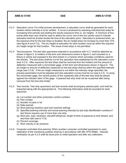
4.2.3 Saturation curve: For initial process development, a saturation curve shall be generated for each<br />
location where intensity is to be verified. A curve is produced by exposing individual test strips for<br />
increasing time periods and plotting the results (exposure time vs. arc height). A minimum of four<br />
points other than zero shall be used to define the curve; one of the four points used to indicate<br />
saturation shall be at least double the time of the saturation point. Saturation is achieved when, as<br />
the exposure time for the test strips is doubled, the arc height does not increase by more than 10%<br />
(see figure 8 and 6.12). The arc height at saturation for each location must be within the required<br />
arc height range for that location. The reuse of test strips is not permitted.<br />
4.2.4 Test procedure: The test strip specimens selected in accordance with 4.2.1 shall be attached as<br />
shown in figure 5, to holders of the form and dimensions shown in figure 4, and mounted on a<br />
fixture or article and exposed to the shot stream in a manner which simulates conditions used for<br />
the articles. The test strips shall be run for the saturation time established by the saturation curve<br />
(see 4.2.3). After exposure the test strips shall be removed from the holders and the amount of<br />
deflection measured with a micrometer gage, of the form and dimensions shown in figure 6. The<br />
arc height or amount of deflection measured on the test strips shall be within the specified intensity<br />
range (see 3.3.6). If the arc height measured is not within the intensity range specified, the<br />
process parameters must be adjusted and new saturation curves must be run (see 4.2.3). In using<br />
the micrometer gage, the central portion of the unpeened side of the test strip shall be placed<br />
against the indicator stem of the gage. A peened test strip shall not be re-peened after being<br />
removed from the test strip holder.<br />
4.2.5 Test records: Test strip specimens and test records shall accompany peened parts, and shall be<br />
inspected along with the appropriate lot. The following information shall be recorded for each<br />
specimen:<br />
(a) Lot number and other production control numbers<br />
(b) Part number<br />
(c) Number of parts in lot<br />
(d) Date peened<br />
(e) Shot peening machine used and machine settings<br />
(f) Specified peening intensity and actual peening intensity by test strip identification numbers if<br />
test fixture requires use of more than one strip<br />
(g) Shot size, type, hardness, standoff (distance), length of time of exposure to shot stream, and<br />
shot flow rate (see 6.17.6)<br />
(h) Percent coverage<br />
(i) Shot velocity or air pressure<br />
4.2.6 Computer-controlled shot peening: When auxiliary computer controlled equipment is used,<br />
calibration of the monitoring systems shall be in accordance with MIL-STD-45662. Intensity<br />
verification as per 4.2.4 shall be done prior to initial operation and after any calibration.<br />
- 8 -


