MIC Green Book
MIC Green Book
MIC Green Book

You also want an ePaper? Increase the reach of your titles
YUMPU automatically turns print PDFs into web optimized ePapers that Google loves.
Shot Peening<br />
A P P L I C A T I O N S<br />
METAL IMPROVEMENT COMPANY<br />
A Subsidiary of Curtiss-Wright Corporation<br />
NINTH EDITION
T A B L E O F C O N T E N T S<br />
INTRODUCTION ............................................................. 3<br />
CHAPTER 1:<br />
THEORY<br />
The Shot Peening Process........................................................................ 4<br />
Shot Peening Residual Stress .................................................................. 5<br />
Summation of Applied and Residual Stress ............................................. 6<br />
Application Case Study: NASA Langley Crack Growth Study .................... 6<br />
Depth of Residual Stress.......................................................................... 7<br />
Shot Peening Media ................................................................................. 7<br />
Effect of Shot Hardness............................................................................ 7<br />
CHAPTER 2:<br />
RESPONSE OF METALS<br />
High Strength Steels ................................................................................ 8<br />
Carburized Steels ..................................................................................... 9<br />
Application Case Study: High Performance Crankshafts .......................... 9<br />
Decarburization........................................................................................ 9<br />
Application Case Study: Reduction of Retained Austenite...................... 10<br />
Austempered Ductile Iron....................................................................... 10<br />
Cast Iron................................................................................................. 10<br />
Aluminum Alloys ..................................................................................... 11<br />
Application Case Study: High Strength Aluminum .................................. 11<br />
Titanium ................................................................................................. 12<br />
Magnesium............................................................................................. 12<br />
Powder Metallurgy ................................................................................. 12<br />
Application Case Study: High Density Powder Metal Gears.................... 13<br />
CHAPTER 3:<br />
MANUFACTURING PROCESSES<br />
Effect on Fatigue Life .............................................................................. 14<br />
Welding .................................................................................................. 14<br />
Application Case Study: Fatigue of Offshore Steel Structures ................ 15<br />
Application Case Study: Turbine Engine HP Compressor Rotors ............ 15<br />
Grinding ................................................................................................. 16<br />
Plating .................................................................................................... 16<br />
Anodizing ............................................................................................... 17<br />
Application Case Study: Anodized Aluminum Rings............................... 17<br />
Plasma Spray.......................................................................................... 17<br />
Electro-Discharge Machining (EDM) ....................................................... 17<br />
Electro-Chemical Machining (ECM)......................................................... 18<br />
Application Case Study: Diaphragm Couplings ...................................... 18<br />
CHAPTER 4:<br />
BENDING FATIGUE<br />
Bending Fatigue ..................................................................................... 19<br />
Gears...................................................................................................... 19<br />
Connecting Rods.................................................................................... 20<br />
Crankshafts ............................................................................................ 21<br />
Application Case Study: Diesel Engine Crankshafts ............................... 21<br />
Application Case Study: Turbine Engine Disks ....................................... 21<br />
CHAPTER 5:<br />
TORSIONAL FATIGUE<br />
Torsional Fatigue.................................................................................... 22<br />
Compression Springs............................................................................. 22<br />
Drive Shafts ........................................................................................... 23<br />
Torsion Bars........................................................................................... 23<br />
Application Case Study: Automotive Torsion Bars ................................. 23<br />
CHAPTER 6:<br />
AXIAL FATIGUE<br />
Axial Fatigue .......................................................................................... 24<br />
Application Case Study: Train Emergency Brake Pin.............................. 24<br />
Application Case Study: Auxiliary Power Unit (APU) Exhaust Ducts....... 24<br />
CHAPTER 7:<br />
CONTACT FAILURE<br />
Fretting Failure....................................................................................... 25<br />
Application Case Study: Turbomachinery Blades and Buckets............... 25<br />
Pitting .....................................................................................................25<br />
Galling ................................................................................................... 26<br />
CHAPTER 8:<br />
CORROSION FAILURE<br />
Corrosion Failure.................................................................................... 27<br />
Stress Corrosion Cracking...................................................................... 27<br />
Application Case Study: Fabrication of Chemical Handling Equipment .... 28<br />
Corrosion Fatigue................................................................................... 28<br />
Application Case Study: Sulfide Stress Cracking.................................... 28<br />
Application Case Study: Medical Implants............................................. 29<br />
Intergranular Corrosion.......................................................................... 29<br />
CHAPTER 9:<br />
THERMAL FATIGUE & HEAT EFFECTS<br />
Effects of Heat ....................................................................................... 30<br />
Thermal Fatigue...................................................................................... 31<br />
Application Case Study: Feedwater Heaters ........................................... 31<br />
CHAPTER 10:<br />
OTHER APPLICATIONS<br />
Peen Forming ......................................................................................... 32<br />
Contour Correction................................................................................. 33<br />
Work Hardening ..................................................................................... 33<br />
Peentex sm ............................................................................................... 34<br />
Engineered Surfaces .............................................................................. 34<br />
Application Case Study: Pneumatic Conveyor Tubing............................ 35<br />
Application Case Study: Food Industry .................................................. 35<br />
Exfoliation Corrosion.............................................................................. 36<br />
Porosity Sealing..................................................................................... 36<br />
Internal Surfaces and Bores................................................................... 36<br />
Dual (Intensity) Peening ........................................................................ 37<br />
The C.A.S.E. sm Process ............................................................................ 38<br />
On-Site Shot Peening............................................................................. 38<br />
Strain Peening ....................................................................................... 39<br />
CHAPTER 11:<br />
CONTROLLING THE PROCESS<br />
Controlling the Process.......................................................................... 40<br />
Media Control ........................................................................................ 40<br />
Intensity Control..................................................................................... 41<br />
Coverage Control ................................................................................... 42<br />
Automated Shot Peening Equipment ..................................................... 43<br />
Application Case Study: CMSP Increases Turbine Engine Service Life ...... 44<br />
Specifying Shot Peening ........................................................................ 45<br />
CHAPTER 12:<br />
ADDITIONAL CAPABILITIES & SERVICES<br />
Peenstress sm – Residual Stress Modeling ............................................... 46<br />
Laser Peening ........................................................................................ 46<br />
Coating Services .................................................................................... 47<br />
Heat Treating ......................................................................................... 48<br />
Valve Reeds – Manufacturing................................................................. 48<br />
APPENDIX:<br />
Conversion Tables............................................................................. 50-51<br />
<strong>MIC</strong> Technical Article Reprints.......................................................... 52-57<br />
<strong>MIC</strong> Facilities Listing ........................................................................ 58-59<br />
1
N O T E S<br />
2
M<br />
Metal Improvement Company (<strong>MIC</strong>) is a world leader in providing specialized metal treatment<br />
services that enhance the performance and extend the life of components operating in a wide<br />
range of applications. Our services are an integral part of the manufacturing process for producing<br />
engineered products for the aerospace, automotive, chemical, medical, power generation and<br />
general industrial markets.<br />
Through a network of over 50 facilities in North America and Europe, <strong>MIC</strong> provides the following<br />
metal treatment services:<br />
Shot Peening – <strong>MIC</strong> has specialized in providing shot peening services to industry since 1945.<br />
Shot peening protects components against failure mechanisms such as fatigue, fretting fatigue<br />
and stress corrosion cracking. We continue to develop new processing techniques and equipment<br />
that help prevent premature part failures and enable designs to achieve their maximum potential.<br />
Laser Peening – <strong>MIC</strong> is the world’s leading provider of laser peening services. With surgical<br />
precision, a unique high energy laser is fired at the surface of a metal part, generating pressure<br />
pulses of one million pounds per square inch. Similar to shot peening, the layer of beneficial<br />
compressive stress increases the component’s resistance to failure mechanisms, which translates<br />
to increased component life and reduced maintenance costs.<br />
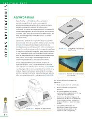
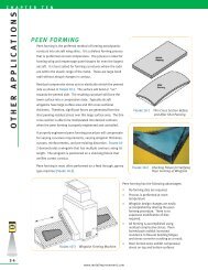
Peen Forming – Peen forming is a highly effective process for creating aerodynamic contours in<br />
aircraft wing skins and for straightening precision metal parts that have become warped due to<br />
prior machining, grinding or heat treating. The imparted residual compressive stresses from the<br />
shot peen forming process that shape the wing skins also increase their resistance to flexural<br />
bending fatigue and stress corrosion cracking.<br />
Heat Treating – <strong>MIC</strong> specializes in the thermal processing of metal components used in a wide<br />
range of industries. Thermal processing relieves stresses within fabricated metal parts and<br />
improves their overall strength, ductility and hardness. By involving <strong>MIC</strong> at the planning stage<br />
of your project, we can recommend the configuration, alloy and thermal process to meet your<br />
design requirements.<br />
Coating Services – Our E/M Coating Services Division has over 40 years of experience in applying<br />
critical tolerance coatings and is a pioneer in the development and application of solid film lubricant<br />
coatings. Selection of the proper coating can facilitate the use of less expensive metals, improve<br />
component wear life and reduce maintenance costs.<br />
Each <strong>MIC</strong> facility maintains quality approvals appropriate to its customer base, such as FAA, CAA,<br />
Nadcap, QS 9000, ISO 9001, AS 9100 and TS16949 certifications.<br />
Metal Improvement Company is a wholly-owned subsidiary of the Curtiss-Wright Corporation<br />
(NYSE:CW). Curtiss-Wright Corporation is a diversified global company that designs, manufactures<br />
and overhauls products for motion control and flow control applications in addition to providing<br />
metal treatment services. For more information about Curtiss-Wright visit www.curtisswright.com.<br />
Copyright © 2005<br />
By<br />
Metal Improvement Company<br />
I N T R O D U C T I O N<br />
Shot Peening<br />
Laser Peening<br />
Peen Forming<br />
Heat Treating<br />
Coating Services<br />
3
C H A P T E R O N E<br />
THEOR Y<br />
4<br />
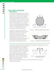
THE SHOT PEENING PROCESS<br />
Shot peening is a cold working process in which the<br />
surface of a part is bombarded with small spherical<br />
media called shot. Each piece of shot striking the<br />
metal acts as a tiny peening hammer imparting a<br />
small indentation or dimple on the surface. In order<br />
for the dimple to be created, the surface layer of the<br />
metal must yield in tension (Figure 1-1). Below the<br />
surface, the compressed grains try to restore the<br />
surface to its original shape producing a hemisphere<br />
of cold-worked metal highly stressed in compression<br />
(Figure 1-2). Overlapping dimples develop a<br />
uniform layer of residual compressive stress.<br />
It is well known that cracks will not initiate nor<br />
propagate in a compressively stressed zone.<br />
Because nearly all fatigue and stress corrosion<br />
failures originate at or near the surface of a part,<br />
compressive stresses induced by shot peening<br />
provide significant increases in part life. The<br />
magnitude of residual compressive stress produced<br />
by shot peening is at least as great as half the<br />
tensile strength of the material being peened.<br />
In most modes of long term failure the common<br />
denominator is tensile stress. These stresses can<br />
result from externally applied loads or be residual<br />
stresses from manufacturing processes such as<br />
welding, grinding or machining. Tensile stresses<br />
attempt to stretch or pull the surface apart and may<br />
eventually lead to crack initiation (Figure 1-3).<br />
Compressive stress squeezes the surface grain<br />
boundaries together and will significantly delay the<br />
initiation of fatigue cracking. Because crack growth<br />
is slowed significantly in a compressive layer,<br />
increasing the depth of this layer increases crack<br />
resistance. Shot peening is the most economical<br />
and practical method of ensuring surface<br />
residual compressive stresses.<br />
www.metalimprovement.com<br />
Dimple<br />
Impact at high speed<br />
creates a dimple<br />
Dimple<br />
Figure 1-1 Mechanical Yielding at Point of Impact<br />
Stretched Surface<br />
COMPRESSION<br />
Stretched Surface<br />
COMPRESSION<br />
Impact at high speed<br />
creates a dimple<br />
Figure 1-2 Compression Resists Fatigue Cracking<br />
Figure 1-3 Crack Initiation and Growth<br />
Through Tensile Stress
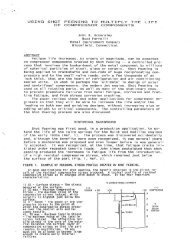
Shot peening is primarily used to combat metal fatigue. The following points pertain to metal fatigue and<br />
its application to the Typical Stress versus Load Cycles graph shown in Figure 1-4.<br />
• Fatigue loading<br />
consists of tens of<br />
thousands to millions<br />
of repetitive load<br />
cycles. The loads<br />
create applied tensile<br />
stress that attempt to<br />
stretch/pull the<br />
surface of the<br />
material apart.<br />
• A linear reduction in<br />
tensile stress results<br />
in an exponential<br />
increase in fatigue life<br />
(Number of Load<br />
Cycles). The graph<br />
(Figure 1-4) shows<br />
that a 38 ksi (262<br />
MPa) reduction in<br />
stress (32%) results in<br />
Figure 1-4 Typical Stress vs Load Cycles<br />
a 150,000 cycle life increase (300%).<br />
SHOT PEENING RESIDUAL STRESS<br />
The residual stress generated by<br />
shot peening is of a compressive<br />
nature. This compressive stress<br />
offsets or lowers applied tensile<br />
stress. Quite simply, less (tensile)<br />
stress equates to longer part life.<br />
A typical shot peening stress profile<br />
is depicted in Figure 1-5.<br />
Maximum Compressive Stress –<br />
This is the maximum value of<br />
compressive stress induced. It is<br />
normally just below the surface.<br />
As the magnitude of the maximum<br />
compressive stress increases so<br />
does the resistance to fatigue<br />
cracking.<br />
Figure 1-5 Typical Shot Peening Residual Stress Profile<br />
Depth of Compressive Layer – This is the depth of the compressive layer resisting crack growth. The layer<br />
depth can be increased by increasing the peening impact energy. A deeper layer is generally desired for<br />
crack growth resistance.<br />
Surface Stress – This magnitude is usually less than the Maximum Compressive Stress.<br />
www.metalimprovement.com<br />
C H A P T E R O N E<br />
THEOR Y<br />
5
C H A P T E R O N E<br />
THEOR Y<br />
6<br />
SUMMATION OF APPLIED AND RESIDUAL STRESS<br />
When a component is shot peened and subjected to<br />
an applied load, the surface of the component<br />
experiences the net stress from the applied load and<br />
shot peening residual stress. Figure 1-6 depicts a<br />
bar with a three-point load that creates a bending<br />
stress at the surface.<br />
The diagonal dashed line is the tensile stress created<br />
from the bending load. The curved dashed line is the<br />
(residual) compressive stress from shot peening. The<br />
solid line is the summation of the two showing a<br />
significant reduction of tensile stress at the surface.<br />
Shot peening is highly advantageous for the<br />
following two conditions:<br />
• Stress risers • High strength<br />
materials<br />
Stress risers may consist of radii, notches, cross holes, grooves, keyways, etc. Shot peening induces a high<br />
magnitude, localized compressive stress to offset the stress concentration factor created from these<br />
geometric changes.<br />
Shot peening is ideal for high strength materials. Compressive stress is directly correlated to a material’s<br />
tensile strength. The higher the tensile strength, the more compressive stress that can be induced. Higher<br />
strength materials have a more rigid crystal structure. This crystal lattice can withstand greater degrees of<br />
strain and consequently can store more residual stress.<br />
Application Case Study<br />
NASA LANGLEY CRACK GROWTH STUDY<br />
Figure 1-6 Resultant Stress in a Shot Peened<br />
Beam with an External Load Applied<br />
Engineers at NASA performed a study on crack growth rates of 2024-T3 aluminum with and without shot<br />
peening. The samples were tested with an initial crack of 0.050" (1.27 mm) and then cycle tested to failure. It<br />
should be noted that the United States Air Force damage tolerance rogue flaw is 0.050" (1.27 mm).<br />
It was found that crack growth was significantly delayed when shot peening was included. As the following<br />
results demonstrate, at a 15 ksi (104 MPa) net stress condition the remaining life increased by 237%. At a 20<br />
ksi (138 MPa) net stress condition the remaining life increased by 81%.<br />
This test reflects conditions that are harsher than real world conditions. Real world conditions would generally<br />
not have initial flaws and should respond with better fatigue life improvements at these stress levels.<br />
NON-SHOT PEENED TEST RESULTS<br />
Net Number Average<br />
Stress Of Tests Life Cycles<br />
15 ksi 2 75,017<br />
20 3 26,029<br />
SHOT PEENED TEST RESULTS<br />
Net Number Average Percent<br />
Stress Of Tests Life Cycles Increase<br />
15 ksi 2 253,142 237%<br />
20 3 47,177 81%<br />
Note on sample preparation: A notch was placed in the surface via the EDM process. The samples were loaded<br />
in fatigue until the crack grew to ~ 0.050" (1.27 mm). If samples were shot peened, they were peened after the<br />
initial crack of 0.050" (1.27 mm) was generated. This was the starting point for the above results. [Ref 1.1]<br />
www.metalimprovement.com
DEPTH OF RESIDUAL STRESS<br />
The depth of the compressive layer is influenced by<br />
variations in peening parameters and material hardness [Ref<br />
1.2]. Figure 1-7 shows the relationship between the depth<br />
of the compressive layer and the shot peening intensity for<br />
five materials: steel 30 HRC, steel 50 HRC, steel 60 HRC,<br />
2024 aluminum and titanium 6Al-4V. Depths for materials<br />
with other hardness values can be interpolated.<br />
SHOT PEENING MEDIA<br />
Media used for shot peening (also see Chapter 11) consists<br />
of small spheres of cast steel, conditioned cut wire (both<br />
carbon and stainless steel), ceramic or glass materials.<br />
Most often cast or wrought carbon steel is employed.<br />
Stainless steel media is used in applications where iron<br />
contamination on the part surface is of concern.<br />
Carbon steel cut wire, conditioned into near round shapes,<br />
is being specified more frequently due to its uniform,<br />
Figure 1-7 Depth of Compression<br />
vs. Almen Arc Height<br />
wrought consistency and great durability. It is available in various grades of hardness and in much tighter<br />
size ranges than cast steel shot.<br />
Glass beads are also used where iron contamination is of<br />
concern. They are generally smaller and lighter than other<br />
media and can be used to peen into sharp radii of threads<br />
and delicate parts where very low intensities are required.<br />
EFFECT OF SHOT HARDNESS<br />
It has been found that the hardness of the shot will<br />
influence the magnitude of compressive stress (Figure 1-8).<br />
The peening media should be at least as hard or harder than<br />
the parts being peened unless surface finish is a critical<br />
factor. For a large number of both ferrous and nonferrous<br />
parts, this criterion is met with regular hardness steel shot<br />
(45-52 HRC).<br />
The increased use of high strength, high hardness steels<br />
(50 HRC and above) is reflected in the use of special<br />
hardness<br />
shot (55-62 HRC).<br />
REFERENCES:<br />
www.metalimprovement.com<br />
C H A P T E R O N E<br />
Figure 1-8 Peening 1045 Steel (Rc 50+) [Ref 1.3]<br />
1.1 Dubberly, Everett, Matthews, Prabhakaran, Newman; The Effects of Shot and Laser Peening on Crack Growth and Fatigue Life in 2024<br />
Aluminum Alloy and 4340 Steel, US Air Force Structural Integrity Conference, 2000<br />
1.2 Fuchs; Shot Peening Stress Profiles<br />
1.3 Lauchner, WESTEC Presentation March 1974, Northrup Corporation; Hawthorne, California<br />
THEOR Y<br />
7
C H A P T E R T W O<br />
RESPONSE OF METALS<br />
8<br />
HIGH STRENGTH STEELS<br />
The residual compressive stress induced by shot peening is a percentage of the ultimate tensile strength<br />
and this percentage increases as the strength/hardness increases. Higher strength/hardness metals<br />
tend to be brittle and sensitive to surface notches. These conditions can be overcome by shot peening<br />
permitting the use of<br />
high strength metals in<br />
fatigue prone<br />
applications. Aircraft<br />
landing gear are often<br />
designed to strength<br />
levels of 300 ksi (2068<br />
MPa) that incorporate<br />
shot peening. Figure 2-<br />
1 shows the relationship<br />
between shot peening<br />
and use of higher<br />
strength materials.<br />
Without shot peening,<br />
optimal fatigue<br />
Figure 2-1 Fatigue Strength vs. Ultimate Tensile Strength<br />
properties for machined<br />
steel components are obtained at approximately 30 HRC. At higher strength/hardness levels, materials<br />
lose fatigue strength due to increased notch sensitivity and brittleness. With the addition of compressive<br />
stresses, fatigue strength increases proportionately to increasing strength/hardness. At 52 HRC, the<br />
fatigue strength of the shot peened specimen is 144 ksi (993 MPa), more than twice the fatigue strength<br />
of the unpeened, smooth specimen [Ref 2.1].<br />
Typical applications that take advantage of high strength/hardness and excellent fatigue properties with<br />
shot peening are impact wrenches and percussion tools. In addition, the fatigue strength of peened<br />
parts is not impaired by shallow scratches that could otherwise be detrimental to unpeened high<br />
strength steel [Ref 2.2].<br />
www.metalimprovement.com
CARBURIZED STEELS<br />
Carburizing and carbonitriding are heat treatment processes that result in very hard surfaces. They are<br />
commonly 55-62 HRC. The benefits of shot peening carburized steels are as follows:<br />
• High magnitudes of compressive stress of ~ 200 ksi (1379 MPa) or greater offer<br />
excellent fatigue benefits<br />
• Carburizing anomalies resulting from surface intergranular oxidation are reduced.<br />
Shot hardness of 55-62 HRC is recommended for fully carburized and carbonitrided parts if maximum<br />
fatigue properties are desired.<br />
Application Case Study<br />
HIGH PERFORMANCE CRANKSHAFTS<br />
Crankshafts for 4-cylinder<br />
high performance engines<br />
were failing prematurely<br />
after a few hours running on<br />
test at peak engine loads.<br />
Testing proved that gas<br />
carburizing and shot peening<br />
the crankpins gave the best<br />
fatigue performance (Figure<br />
2-2). Results from nitriding<br />
and shot peening also<br />
demonstrated favorable<br />
results over the alternative<br />
to increase the crankpin<br />
diameter [Ref 2.3].<br />
Figure 2-2 Comparison of Shot Peened<br />
Nitrided and Gas Carburized Crank Pins<br />
DECARBURIZATION<br />
Decarburization is the reduction in surface carbon content of a ferrous alloy during thermal processing.<br />
It has been shown that decarburization can reduce the fatigue strength of high strength steels (240 ksi,<br />
1650 MPa or above) by 70-80% and lower strength steels (140-150 ksi, 965-1030 MPa) by 45-55%<br />
[Refs 2.4, 2.5 and 2.6].<br />
Decarburization is a surface phenomenon not particularly related to depth. A depth of 0.003 inch<br />
decarburization can be as detrimental to fatigue strength as a depth of 0.030 inch [Refs 2.4, 2.5 and 2.6].<br />
www.metalimprovement.com<br />
C H A P T E R T W O<br />
RESPONSE OF METALS<br />
9
C H A P T E R T W O<br />
RESPONSE OF METALS<br />
10<br />
Shot peening has proven to be effective in restoring most of the fatigue strength lost due to decarburization<br />
[Ref 2.7]. Because the decarburized layer is not easily detectable on quantities of parts, peening can<br />
insure the integrity of the parts if decarburization is suspected. If a gear that is intended to have a high<br />
surface hardness (58+ HRC) exhibits unusually heavy dimpling after peening, decarburization should<br />
be suspected.<br />
Decarburization is often accompanied with the undesirable metallurgical condition of retained austenite.<br />
By cold working the surface, shot peening reduces the percentage of retained austenite.<br />
Application Case Study<br />
REDUCTION OF RETAINED AUSTENITE - 5120 CARBURIZED STEEL,<br />
SHOT PEENED AT 0.014" (0.36 mm) A INTENSITY<br />
Retained Austenite<br />
(Volume %)<br />
Depth (inches) Depth (mm) Unpeened Peened<br />
0.0000 0.00 5 3<br />
0.0004 0.01 7 4<br />
0.0008 0.02 14 5<br />
0.0012 0.03 13 6<br />
0.0016 0.04 14 7<br />
0.0020 0.05 14 7<br />
0.0024 0.06 15 8<br />
0.0028 0.07 15 9<br />
0.0039 0.10 15 10<br />
0.0055 0.14 12 10<br />
[Ref 2.8]<br />
AUSTEMPERED DUCTILE IRON<br />
Improvements in austempered ductile iron (ADI) have allowed it to replace steel forgings, castings, and<br />
weldments in some engineering applications. ADI has a high strength-to-weight ratio and the benefit of<br />
excellent wear capabilities. ADI has also replaced aluminum in certain high strength applications as it is at<br />
least 3 times stronger and only 2.5 times more dense. With the addition of shot peening, the allowable<br />
bending fatigue strength of ADI can be increased up to 75%. This makes certain grades of ADI with shot<br />
peening comparable to case-carburized steels for gearing applications [Ref 2.9].<br />
CAST IRON<br />
There has been an increased demand in recent years for nodular cast iron components that are capable of<br />
withstanding relatively high fatigue loading. Cast iron components are often used without machining in<br />
applications where the cast surface is subject to load stresses. The presence of imperfections at casting<br />
surfaces in the form of pinholes, dross or flake graphite can considerably reduce the fatigue properties of<br />
unmachined pearlitic nodular irons. The unnotched fatigue limit may be reduced by as much as 40%,<br />
depending on the severity of the imperfections at the casting surface.<br />
www.metalimprovement.com
Shot peening can significantly improve properties when small cast-surface imperfections are present. One<br />
application is diesel engine cylinder liners. At the highest shot peening intensity used in the tests, the<br />
fatigue limit was 6% below that of fully machined fatigue specimens. This compares to a reduction of 20%<br />
for specimens in the as-cast unpeened condition. Visually, the peening on the as-cast surface has a<br />
polishing effect leaving the appearance of smoothing the rougher as-cast surface [Ref 2.10].<br />
ALUMINUM ALLOYS<br />
Traditional high strength aluminum alloys (series 2000 and 7000) have been used for decades in the aircraft<br />
industry because of their high strength-to-weight ratio. The following aluminum alloys have emerged with<br />
increasing use in critical aircraft/aerospace applications and respond equally well to shot peening:<br />
• Aluminum Lithium Alloys (Al-Li)<br />
• Isotropic Metal Matrix Composites (MMC)<br />
• Cast Aluminum (Al-Si)<br />
Application Case Study<br />
Al 7050-T7651 HIGH STRENGTH ALUMINUM<br />
Fatigue specimens were<br />
prepared from high strength<br />
Al 7050-T7651. All four sides<br />
of the center test portion<br />
were shot peened. Fatigue<br />
tests were conducted under<br />
a four-point reversed<br />
bending mode (R = -1). The<br />
S-N curve of the shot peened<br />
versus non-shot peened<br />
alloy is shown in Figure 2-3.<br />
It was found that shot<br />
peening improved the<br />
fatigue endurance limit by<br />
Figure 2-3 S-N Curves for Shot Peened<br />
approximately 33%. Even in<br />
a regime where the stress<br />
Aluminum Alloy 7050-T7651<br />
ratio is between the yield strength and the endurance limit, the fatigue strength increased by a factor of<br />
2.5 to almost 4 [Ref 2.11].<br />
www.metalimprovement.com<br />
C H A P T E R T W O<br />
RESPONSE OF METALS<br />
11
C H A P T E R T W O<br />
RESPONSE OF METALS<br />
12<br />
TITANIUM<br />
High Cycle Fatigue (HCF) - HCF of titanium is<br />
illustrated by Figure 2-4, which compares the<br />
capabilities of titanium alloy connecting rods<br />
for a high performance European sports car.<br />
The rods are manufactured using various<br />
processes. With shot peening, the fatigue<br />
limit was increased by approximately 20%<br />
while weight was reduced by some 40% as<br />
compared to steel connecting rods [Ref 2.12].<br />
Low Cycle Fatigue (LCF) - As is typical with<br />
other metals, the fatigue response with shot<br />
peening increases with higher cycle fatigue.<br />
Higher cycle fatigue would be associated with<br />
lower stresses whereas lower cycle fatigue<br />
would be associated with higher stress levels.<br />
This is demonstrated graphically in the S-N<br />
Curve (Figure 1-4) and also Figure 2-5.<br />
Figure 2-4 Comparison of Fatigue Strengths for Polished<br />
and Shot Peened Titanium Ti6A14V<br />
Figure 2-5 shows the results of shot peening<br />
titanium dovetail slots on a rotating engine<br />
component [Ref 2.13]. There are two baseline<br />
load curves that are not shot peened. When<br />
shot peening is applied, the base line curve<br />
that initially had more cycles to failure<br />
responded significantly better. Note that<br />
improvements in fatigue life are on an<br />
exponential basis.<br />
Figure 2-5 LCF Benefits from Shot Peening Notched Ti8-1-1<br />
The most common application of LCF for<br />
titanium is the rotating turbine engine hardware (discs, spools, and shafts) with the exception of blades. These<br />
components are shot peened to increase durability. Each takeoff and landing is considered one load cycle.<br />
MAGNESIUM<br />
Magnesium alloys are not commonly used in fatigue applications. However, when used for the benefit of weight<br />
reduction, special peening techniques can be employed to achieve 25 - 35% improvement in fatigue strength.<br />
POWDER METALLURGY<br />
Optimized peening parameters have been shown to raise the endurance limit of sintered steel PM alloys by<br />
22% and the fatigue life by a factor of 10. [Ref. 2.14] Automotive components such as gears and connecting<br />
rods are candidates for PM with shot peening. Shot peening is most effective on higher density PM parts<br />
such as forged powder metal components.<br />
Surface densification by shot peening can increase the fatigue limit significantly, especially in the case of<br />
bending. The surface densification also assists in the closing of surface porosity of PM components for<br />
sealing and other engineering applications.<br />
www.metalimprovement.com
Pressed and sintered ferrous powder materials are in increasing demand as the PM industry has grown into<br />
applications involving more highly stressed components. Ancorsteel 1000B with 2% copper and 0.9% graphite<br />
had an endurance limit of 35 ksi (240 MPa) when tested without shot peening. Shot peening the test specimens<br />
increased the endurance limit 16% to 40.5 ksi (280 MPa) [Ref 2.16].<br />
REFERENCES:<br />
Application Case Study<br />
HIGH DENSITY POWDER METAL GEARS<br />
Tooth root bending fatigue studies were performed using pulsator tests to compare a reference wrought gear steel<br />
to a 7.5 g/cm 3 powdered metal gear. Both gears were 3.5 mm module consisting of 25 teeth and case hardened<br />
to 60 HRC. The wrought gear was a 16MnCr5 steel and the powdered metal gear was Fe-3.5Mo alloy content.<br />
In Figure 2-6 the powdered metal gear results are<br />
depicted with the blue curves. The endurance<br />
limit improved ~ 35% with the addition of shot<br />
peening. The endurance limit improved from<br />
~ 95 ksi (650 MPa) to ~ 128 ksi (880 MPa). The<br />
endurance limit of the shot peened powdered<br />
metal compares very closely with the non-peened<br />
16MnCr5 material. Due to the significant cost<br />
savings of powdered metal, the shot peened<br />
powder metal gear may be a suitable replacement<br />
to the more expensive wrought steel gear. Shot<br />
peening was performed at 0.013” A (0.32 mm A)<br />
intensity for all samples [Ref 2.15].<br />
2.1 Horger; Mechanical and Metallurgical Advantages of Shot Peening – Iron Age Reprint 1945<br />
2.2 Hatano and Namitki; Application of Hard Shot Peening to Automotive Transmission Gears, Special Steel Research Laboratory, Daido Steel<br />
Company, Ltd., Japan<br />
2.3 Challenger; Comparison of Fatigue Performance Between Engine Crank Pins of Different Steel Types and Surface Treatments, Lucas Research<br />
Center, Solihull, England, July 1986<br />
2.4 Properties and Selection, Metals Handbook, Eighth Edition, Vol. 1, pp. 223-224<br />
2.5 Jackson and Pochapsky; The Effect of Composition on the Fatigue Strength of Decarburized Steel, Translations of the ASM, Vol. 39, pp. 45-60<br />
2.6 Bush; Fatigue Test to Evaluate Effects of Shot Peening on High Heat Treat Steel - Lockheed Report No. 9761<br />
2.7 Gassner; Decarburization and Its Evaluation by Chord Method, Metal Progress, March 1978, pp. 59-63<br />
2.8 Internal Metal Improvement Company Memo<br />
2.9 Keough, Brandenburg, Hayrynen; Austempered Gears and Shafts: Tough Solutions, Gear Technology March/April 2001, pp. 43-44<br />
2.10 Palmer; The Effects of Shot Peening on the Fatigue Properties of Unmachined Pearlitic Nodular Graphite Iron Specimens Containing Small<br />
Cast Surface Imperfections, BCIRA Report #1658, The Casting Development Centre, Alvechurch, Birmingham, UK<br />
2.11 Oshida and Daly; Fatigue Damage Evaluation of Shot Peened High Strength Aluminum Alloy, Dept. of Mechanical and Aerospace Engineering,<br />
Syracuse University, Syracuse, NY<br />
2.12 Technical Review, Progress in the Application of Shot-Peening Technology for Automotive Engine Components, Yamaha Motor Co., Ltd., 1998<br />
2.13 McGann and Smith; Notch Low Cycle Fatigue Benefits from Shot Peening of Turbine Disk Slots<br />
2.14 Sonsino, Schlieper, Muppman; How to Improve the Fatigue Properties of Sintered Steels by Combined Mechanical and Thermal Surface<br />
Treatments, Modern Developments in Powder Metallurgy, Volume 15 - 17, 1985<br />
2.15 Strehl, R., 2001, “Load Capacity of Gears Made From High Strength Powder Metal Steel,” Doctorate Thesis Study, University of Aachen, Germany<br />
2.16 O’Brian; Impact and Fatigue Characterization of Selected Ferrous P/M Materials, Annual Powder Metallurgy Conference, Dallas, TX. May 1987<br />
Tooth Root Strength - ksi<br />
Figure 2-6 Fatigue Life Curves Comparing a<br />
Reference (16MnCr5) Wrought Steel to a<br />
7.5 g/cm 3 Powdered Metal (Fe-3.5Mo)<br />
with and without Shot Peening.<br />
www.metalimprovement.com<br />
C H A P T E R T W O<br />
MPa<br />
RESPONSE OF METALS<br />
13
C H A P T E R T H R E E<br />
M ANUFACTURING PROCESSES<br />
14<br />
EFFECT ON FATIGUE LIFE<br />
Manufacturing processes have significant effects on fatigue properties of metal parts. The effects can be<br />
either detrimental or beneficial. Detrimental processes include welding, grinding, abusive machining, metal<br />
forming, etc. These processes leave the surface in residual tension. The summation of residual tensile<br />
stress and applied loading stress accelerates fatigue failure as shown in Figure 1-6.<br />
Beneficial manufacturing processes include surface hardening as it induces some residual compressive<br />
stress into the surface. Honing, polishing and burnishing are surface enhancing processes that remove<br />
defects and stress raisers from manufacturing operations. Surface rolling induces compressive stress but is<br />
primarily limited to cylindrical geometries. Shot peening has no geometry limitations and produces results<br />
that are usually the most economical.<br />
The effect of residual stress on fatigue life is demonstrated in the following example. A test by an airframe<br />
manufacturer on a wing fitting showed the initiation of a crack at just 60% of predicted life. The flaw was<br />
removed and the same area of the part shot peened. The fitting was then fatigue tested to over 300% life<br />
without further cracking even with reduced cross sectional thickness [Ref 3.1].<br />
WELDING<br />
The residual tensile stress from welding is created because the weld consumable is applied in its molten state.<br />
This is its hottest, most expanded state. It then bonds to the base material, which is much cooler. The weld<br />
cools rapidly and attempts to shrink during the cooling. Because it has already bonded to the cooler, stronger<br />
base material it is unable to shrink. The net result is a weld that is essentially being "stretched" by the base<br />
material. The heat affected zone is usually most affected by the residual stress and hence where failure will<br />
usually occur. Inconsistency in the weld<br />
filler material, chemistry, weld geometry,<br />
porosity, etc., act as stress risers for<br />
residual and applied tensile stress to<br />
initiate fatigue failure.<br />
As shown in Figure 3-1, shot peening is<br />
extremely beneficial in reversing the<br />
residual stress from welding that tends to<br />
cause failure in the heat affected zone<br />
from a tensile to a compressive state.<br />
Figure 3-1 demonstrates a number of<br />
interesting changes in residual stress<br />
from welding, thermal stress relieving<br />
and shot peening [Ref 3.2]. Tensile<br />
stresses generated from welding are<br />
Figure 3-1 Residual Stresses from Welding<br />
additive with applied load stresses. This combined stress will accelerate failure at welded connections.<br />
When the weld is stress relieved at 1150 °F (620 °C) for one hour, the tensile stress is reduced to almost zero.<br />
This reduction of tensile stress will result in improved fatigue properties.<br />
www.metalimprovement.com
If the weld is shot peened (rather than stress relieved) there is a significant reversal of residual stress from<br />
tensile to compressive. This will offer significant resistance to fatigue crack initiation and propagation.<br />
Figure 3-1 shows the optimal manufacturing sequence for welding is to stress relieve and then shot<br />
peen. The stress relieving process softens the weld such that inducing a deeper layer of compressive<br />
stress becomes possible.<br />
Application Case Study<br />
FATIGUE OF OFFSHORE STEEL STRUCTURES<br />
A Norwegian research program<br />
concluded that the combination of Steel Condition<br />
Fatigue Strength<br />
At 1,000,000 Cycles<br />
weld toe grinding and shot peening<br />
Base Material ~ 50 ksi (340 MPa)<br />
gave the largest improvement in<br />
Weld Toe Ground and Peened ~ 44 ksi (300 MPa)<br />
the structure life. This corresponds Weld Toe Ground (only) ~ 26 ksi (180MPa)<br />
to more than a 100% increase in<br />
the as-welded strength at one<br />
As Welded (only) ~ 20 ksi (140MPa)<br />
million cycles [Ref 3.3]. Other research shows that the improvement in weld fatigue strength from shot<br />
peening increases in proportion to the yield strength of the parent metal.<br />
The American Welding Society (AWS) Handbook cautions readers to consider residual tensile stresses from<br />
welding if the fabrication is subject to fatigue loading as described in the following statement: "Localized<br />
stresses within a structure may result entirely from external loading, or there may be a combination of<br />
applied and residual stresses. Residual stresses are not cyclic, but they may augment or detract from<br />
applied stresses depending on their respective sign. For this reason, it may be advantageous to induce<br />
compressive residual stress in critical areas of the weldment where cyclic applied stresses are expected".<br />
The use of the shot peening process to improve resistance to fatigue as well as stress corrosion cracking in<br />
welded components is recognized by such organizations as:<br />
• American Society of Mechanical Engineers [Ref. 3.4]<br />
• American Bureau of Shipping [Ref. 3.5]<br />
• American Petroleum Institute [Ref. 3.6]<br />
• National Association of Corrosion Engineers [Ref. 3.7]<br />
Application Case Study<br />
TURBINE ENGINE HP COMPRESSOR ROTORS<br />
Two leading companies in the manufacture of jet turbine engines jointly manufacture high pressure<br />
compressor rotors. Separate pieces are machined from forged titanium (Ti 4Al-6V) and then welded<br />
together. Testing produced the following results:<br />
As Welded 4,000 cycles*<br />
Welded and polished 6,000 cycles<br />
Welded and peened 16,000 cycles<br />
www.metalimprovement.com<br />
* In aircraft engine terminology one cycle<br />
equals the ramp up required for one take-off of<br />
the aircraft for which the engine is configured.<br />
Initially, shot peening was used as additional "insurance" from failure. After many years of failure<br />
free service, coupled with innovations in shot peening controls, shot peening has been incorporated<br />
as a full manufacturing process in engine upgrades [Ref 3.8].<br />
C H A P T E R T H R E E<br />
M ANUFACTURING PROCESSES<br />
15
C H A P T E R T H R E E<br />
M ANUFACTURING PROCESSES<br />
16<br />
GRINDING<br />
Typically, grinding induces residual tensile stress<br />
as a result of localized heat generated during<br />
the process. The metal in contact with the<br />
abrasive medium heats locally and attempts to<br />
expand. The heated material is weaker than the<br />
surrounding metal and yields in compression.<br />
Upon cooling the yielded metal attempts to<br />
contract. This contraction is resisted by the<br />
surrounding metal resulting in residual tensile<br />
stress. Residual tensile stress of any magnitude<br />
will have a negative effect on fatigue life and<br />
resistance to stress corrosion cracking.<br />
Figure 3-2 graphically depicts residual tensile<br />
stress generated from various grinding processes [Ref 3.9]. A 1020, 150-180 BHN carbon steel (with and<br />
without weld) was ground abusively and conventionally. Figure 3-2 shows that the grinding processes<br />
resulted in high surface tension with the abusive grind having a deeper (detrimental) layer of residual tension.<br />
Shot peening after grinding will reverse the residual stress state from tensile to compressive. The beneficial<br />
stress reversal is similar to that from shot peening welded regions in a state of tension.<br />
PLATING<br />
Many parts are shot peened prior to chrome and electroless<br />
nickel plating to counteract the potential harmful effects on<br />
fatigue life. Fatigue deficits from plating may occur from the<br />
micro-cracking in the brittle surface, hydrogen embrittlement<br />
or residual tensile stresses.<br />
Figure 3-3 is a 1200x SEM photograph showing a network of<br />
very fine cracks that is typical of hard chrome plating [Ref 3.10].<br />
Under fatigue loading, the micro-cracks can propagate into<br />
the base metal and lead to fatigue failure.<br />
When the base metal is shot peened, the potential for fatigue<br />
crack propagation into the base metal from the plating is<br />
dramatically reduced. Figure 3-4 illustrates this concept and<br />
assumes dynamic loading on a component.<br />
The graphic on the left shows the micro-cracking propagating into<br />
the base material. When shot peened, the graphic on the right<br />
shows the compressive layer preventing the micro-cracking from<br />
propagating into the base material.<br />
Shot peening prior to plating is recommended on cyclically loaded parts to enhance fatigue properties. For<br />
parts that require unlimited life under dynamic loads, federal specifications QQ-C-320 and MIL-C-26074 call for<br />
shot peening of steel parts prior to chrome or electroless nickel-plating. Other hard plating processes such as<br />
electrolytic nickel may also lower fatigue strength.<br />
www.metalimprovement.com<br />
Figure 3-2 Residual Stresses from Grinding<br />
Figure 3-3 Plating Micro-Cracks<br />
Figure 3-4 Compressive Stress Resists<br />
Micro-Crack Growth
ANODIZING<br />
Hard anodizing is another application in which shot peening improves fatigue resistance of coated<br />
materials. Benefits are similar to those for plating providing the peening is performed to the base<br />
material before anodizing.<br />
Application Case Study<br />
ANODIZED ALUMINUM RINGS<br />
Aluminum (AlZnMgCu 0.5) rings with external teeth were tested for comparison purposes with<br />
anodizing and shot peening. The rings had an outside diameter of ~ 24" (612 mm) and a tensile<br />
strength of ~ 71 ksi (490 MPa). The (hard) anodizing layer was ~ 0.0008" (0.02 mm) thick.<br />
Bending fatigue tests were<br />
conducted to find the load<br />
to cause a 10% failure<br />
probability at one million<br />
cycles. The table shows the<br />
results [Ref 3.11].<br />
PLASMA SPRAY<br />
Plasma spray coatings are primarily used in applications that require excellent wear resistance. Shot<br />
peening has proven effective as a base material preparation prior to plasma spray applications that are<br />
used in cyclic fatigue applications. Shot peening has also been used after the plasma spray application to<br />
improve surface finish and close surface porosity.<br />
ELECTRO-DISCHARGE MACHINING (EDM)<br />
EDM is essentially a "force-free" spark erosion<br />
process. The heat generated to discharge<br />
molten metal results in a solidified recast layer<br />
on the base material. This layer can be brittle<br />
and exhibit tensile stresses similar to those<br />
generated during the welding process. Shot<br />
peening is beneficial in restoring the fatigue<br />
debits created by this process. In Figure 3-5<br />
the effect of shot peening on electro-chemical<br />
machined (ECM), electro-discharge machined<br />
(EDM) and electro-polished (ELP) surfaces is<br />
shown [Ref 3.12]. Figure 3-5 should be viewed<br />
in a clockwise format. ECM, EDM and ELP<br />
fatigue strengths are compared with and<br />
without shot peening.<br />
Shot Peened Hard Anodized Load (10% Failure)<br />
No No 6744 lb / 30 KN<br />
Yes No 9218 lb / 41 KN<br />
No Yes 4496 lb / 20 KN<br />
Yes Yes 10,791 lb / 48 KN<br />
www.metalimprovement.com<br />
Figure 3-5 High Cycle Fatigue Behavior<br />
of Inconel 718<br />
C H A P T E R T H R E E<br />
M ANUFACTURING PROCESSES<br />
17
C H A P T E R T H R E E<br />
M ANUFACTURING PROCESSES<br />
18<br />
ELECTRO-CHE<strong>MIC</strong>AL MACHINING (ECM)<br />
Electro-chemical machining is the controlled dissolution of material by contact with a strong chemical<br />
reagent in the presence of an electric current. A reduction in fatigue properties is attributed to surface<br />
softening (the rebinder effect) and surface imperfections left by preferential attack on grain boundaries.<br />
A shot peening post treatment more than restores fatigue properties as shown in Figure 3-5 [Ref 3.12].<br />
Application Case Study<br />
DIAPHRAGM COUPLINGS<br />
Metal diaphragm couplings are often used in turbomachinery applications. These couplings accommodate<br />
system misalignment through flexing. This flexing, or cyclic loading, poses concerns for fatigue failures.<br />
Researchers concluded that the ECM process produces parts that are geometrically near-perfect. However,<br />
they found under scanning electron microscope observation that small cavities sometimes developed on<br />
the surface as a result of ECM. These cavities apparently generated stress concentrations that lead to<br />
premature failures. Shot peening after ECM was able to overcome this deficiency and has significantly<br />
improved the endurance limit of the diaphragm couplings [Ref 3.13 and 3.14].<br />
REFERENCES:<br />
3.1 Internal Metal Improvement Company Memo<br />
3.2 Molzen, Hornbach; Evaluation of Welding Residual Stress Levels Through Shot Peening and Heat Treating, AWS Basic Cracking<br />
Conference; Milwaukee, WI; July 2000<br />
3.3 Haagensen; Prediction of the Improvement in Fatigue Life of Welded Joints Due to Grinding, TIG Dressing, Weld Shape Control and Shot<br />
peening." The Norwegian Institute of Technology, Trondheim, Norway<br />
3.4 McCulloch; American Society of Mechanical Engineers, Letter to H. Kolin, May 1975<br />
3.5 Stern; American Bureau of Shipping, Letter to G. Nachman, July 1983<br />
3.6 Ubben; American Petroleum Institute, Letter to G. Nachman, February 1967<br />
3.7 N.A.C.E Standard MR-01-75, Sulfide Stress Cracking Resistant Metallic Material for Oilfield Equipment, National Association of Corrosion Engineers<br />
3.8 Internal Metal Improvement Company Memo<br />
3.9 Molzen, Hornbach; Evaluation of Welding Residual Stress Levels Through Shot Peening and Heat Treating, AWS Basic Cracking Conference;<br />
Milwaukee, WI; July 2000<br />
3.10 Metallurgical Associates, Inc; "Minutes" Vol.5 No.1, Winter 1999; Milwaukee, WI<br />
3.11 Internal Metal Improvement Company Memo<br />
3.12 Koster, W.P., Observation on Surface Residual Stress vs. Fatigue Strength, Metcut Research Associates, Inc., Cincinnati, Ohio.<br />
Bulletin 677-1, June 1977<br />
3.13 Calistrat; Metal Diaphragm Coupling Performance, Hydrocarbon Processing, March 1977<br />
3.14 Calistrat; Metal Diaphragm Coupling Performance, 5th Turbomachinery Symposium, Texas A&M University, October 1976<br />
www.metalimprovement.com
BENDING FATIGUE<br />
Bending fatigue is the most<br />
common fatigue failure mode. This<br />
failure mode responds well to shot<br />
peening because the highest<br />
(tensile) stress is at the surface.<br />
Figure 4-1 shows a cantilever beam<br />
under an applied bending load.<br />
The beams deflection causes the<br />
top surface to stretch putting it in a<br />
state of tension. Any radii or<br />
geometry changes along the top<br />
surface would act as stress risers.<br />
Fully reversed bending involves<br />
Figure 4-1 Highest Stress at Surface<br />
components that cycle through tensile and compressive load cycles. This is the most destructive type of<br />
fatigue loading. Fatigue cracks are initiated and propagated from the tensile portion of the load cycle.<br />
GEARS<br />
Shot peening of gears is a very common application. Gears of any<br />
size or design are mainly shot peened to improve bending fatigue<br />
properties in the root sections of the tooth profile. The meshing of<br />
gear teeth is similar to the cantilever beam example. The load<br />
created from the tooth contact creates a bending stress in the root<br />
area below the point of contact (Figure 4-3).<br />
Gears are frequently shot peened after through hardening or<br />
surface hardening. Increased surface hardness results in<br />
proportional increases in compressive stress. Maximum residual<br />
compression from carburized and shot peened<br />
gears can range from 170-230 ksi (1170-1600<br />
MPa) depending on the carburizing treatment<br />
and shot peening parameters (Figure 4-4). It is<br />
common to use hard shot (55-62 HRC) when<br />
shot peening carburized gears. However,<br />
reduced hardness shot (45-52 HRC) may be<br />
used when carburized surfaces require less<br />
disruption of the tooth flank surface. The<br />
amount of compressive stress will be ~ 50% of<br />
that which hard shot will induce.<br />
www.metalimprovement.com<br />
Figure 4-2 Ring and Pinion<br />
Gear Assembly<br />
Figure 4-3 Polarized View of Applied Gear Stresses<br />
C H A P T E R F O U R<br />
BENDING FA TIGUE<br />
19
C H A P T E R F O U R<br />
BENDING FA TIGUE<br />
20<br />
The optimal way to induce resistance<br />
to pitting fatigue near the gear tooth<br />
pitch line is to induce a compressive<br />
stress followed by a lapping, honing or<br />
isotropic finishing process. Care must<br />
be taken to not remove more than 10%<br />
of the shot peening layer. Processes<br />
that refine the surface finish of shot<br />
peening dimples allow the contact load<br />
to be distributed over a larger surface<br />
area reducing contact stresses.<br />
Metal Improvement Company (<strong>MIC</strong>)<br />
offers a shot peening and superfinishing<br />
process called C.A.S.E. SM Figure 4-4 Typical Carburized Gear Residual Stress Profile<br />
that has increased pitting fatigue resistance of gears by 500%. Please see<br />
Chapter 10 for additional information and photomicrographs on this process.<br />
Increases in fatigue strength of 30% or more at 1,000,000 cycles are common in certain gearing<br />
applications. The following organizations/specifications allow for increases in tooth bending loads when<br />
controlled shot peening is implemented:<br />
• Lloyds Register of Shipping: 20% increase [Ref 4.2]<br />
• Det Norske Veritas: 20% increase [Ref 4.3]<br />
• ANSI/AGMA 6032-A94 Marine Gearing Specification: 15% increase<br />
CONNECTING RODS<br />
Connecting rods are excellent examples of metal components subjected to fatigue loading as each engine<br />
revolution results in a load cycle. The critical failure areas on most connecting rods are the radii on either<br />
side of the I-beams next to the large bore. Figure 4-5 shows a finite element stress analysis plot with the<br />
maximum stress areas shown in red.<br />
The most economical method of shot<br />
peening is to peen the as-forged, as-cast<br />
or powdered metal rod prior to any<br />
machining of the bores or faces. This<br />
eliminates masking operations that will<br />
add cost. Rougher surfaces in<br />
compression have better fatigue<br />
properties than smooth surfaces in<br />
tension (or without residual stress) such<br />
that most peened surfaces do not require<br />
prior preparation or post operations.<br />
www.metalimprovement.com<br />
Figure 4-5 Finite Element Stress Plot of a Connecting Rod
CRANKSHAFTS<br />
In most cases, all radii on a crankshaft are shot peened. These<br />
include the main bearing journals and crankpin radii as shown in<br />
Figure 4-6. The most highly stressed area of a crankshaft is the<br />
crank pin bearing fillet. The maximum stress area is the bottom<br />
side of the pin fillet when the engine fires as the pin is in the top<br />
dead center position (Figure 4-6). It is common for fatigue<br />
cracks to initiate in this pin fillet and propagate through the web<br />
of the crankshaft to the adjacent main bearing fillet causing<br />
catastrophic failure.<br />
Experience has shown shot peening to be effective on forged steel,<br />
Figure 4-6 Crankshaft Schematic<br />
cast steel, nodular iron, and austempered ductile iron crankshafts. Fatigue strength increases of 10 to 30% are<br />
allowed by Norway’s Det Norske Veritas providing fillets are shot peened under controlled conditions [Ref 4.5].<br />
Application Case Study<br />
DIESEL ENGINE CRANKSHAFTS<br />
Four point bending fatigue tests were carried out on test pieces from a diesel engine crankshaft. The<br />
material was Armco 17-10 Ph stainless steel. The required service of this crankshaft had to exceed one<br />
hundred million cycles. Fatigue strength of unpeened and shot peened test pieces were measured at one<br />
billion cycles. The fatigue strength for the unpeened material was 43 ksi (293 MPa) versus 56 ksi (386<br />
MPa) for the peened material. This is an increase of ~ 30% [Ref 4.6].<br />
Application Case Study<br />
TURBINE ENGINE DISKS<br />
In 1991 the Federal Aviation Authority issued an<br />
airworthiness directive that required inspection for cracks<br />
in the low pressure fan disk. Over 5,000 engines were in<br />
use on business jets in the United States and Europe.<br />
The FAA required that engines that did not have lance<br />
(shot) peening following machining in the fan blade<br />
dovetail slot be inspected. Those engines having fan<br />
disks without lance peening were required to reduce<br />
service life from 10,000 to 4,100 cycles (takeoffs and<br />
landings). Disks that were reworked with lance peening<br />
per AMS 2432 (Computer Monitored Shot Peening) prior<br />
Figure 4-7 Lance Peening of Fan Disk<br />
to 4,100 cycles were granted a 3,000 cycle extension [Ref 4.7]. A typical lance peening operation of a fan<br />
disk is shown in Figure 4-7. See also Chapter 10 – Internal Surfaces and Bores.<br />
REFERENCES:<br />
4.1 Figure 4-2, Unigraphics Solutions, Inc. website (www.ugsolutions / www.solid-edge.com), June 2000<br />
4.2 Letter to W.C. Classon, Lloyds Register of Shipping, May 1990<br />
4.3 Sandberg; Letter to Metal improvement Company, Det Norske Veritas, September 1983<br />
4.4 Figure 4-5, Unigraphics Solutions, Inc. website (www.ugsolutions / www.solid-edge.com), June 2000<br />
4.5 Sandberg; Letter to Metal improvement Company, Det Norske Veritas, September 1983<br />
4.6 Internal Metal Improvement Company Memo<br />
4.7 FAA Issues AD on TFE73, Aviation week & Space Technology; April 22, 1991<br />
www.metalimprovement.com<br />
C H A P T E R F O U R<br />
BENDING FA TIGUE<br />
21
C H A P T E R F I V E<br />
T O R SIO NAL FA TIGUE<br />
22<br />
TORSIONAL FATIGUE<br />
Torsional fatigue is a failure mode that<br />
responds well to shot peening because<br />
the greatest (tensile) stress occurs at<br />
the surface. Torsional loading creates<br />
stresses in both the longitudinal and<br />
perpendicular directions such that the<br />
maximum tensile stress is 45° to<br />
longitudinal axis of the component.<br />
Figure 5-1 depicts a solid bar loaded<br />
in pure torsion with a crack depicting<br />
reversed torsional loading.<br />
Lower strength materials tend to fail from torsional fatigue in the shear plane perpendicular to the longitudinal<br />
axis. This is because they are weaker in shear than in tension. Higher strength materials tend to fail at 45° to<br />
the longitudinal axis because they are weaker in tension than in shear.<br />
COMPRESSION SPRINGS<br />
Compression springs are subject to high cycle fatigue and are one of the<br />
more common shot peening applications. The spring wire twists allowing<br />
the spring to compress creating a torsional stress. In addition to operating<br />
in high cycle fatigue conditions, the coiling process induces detrimental<br />
tensile stress at the inner diameter (ID) of the spring. Figure 5-3<br />
demonstrates the residual stress after coiling and shot peening.<br />
The spring wire analyzed in Figure 5-3 was a 0.25" (6.35 mm) diameter<br />
Chrome-Silicon material with an<br />
ultimate tensile strength (UTS) of 260<br />
ksi (1793 MPa). The residual tensile<br />
stress at the ID after coiling was ~ 70<br />
ksi (483 MPa) and is the primary<br />
reason for failure at 80,000 load<br />
cycles [Ref 5.2].<br />
Shot peening induced a reversal of<br />
residual stress to a maximum<br />
compressive stress of ~ 150 ksi (1035<br />
MPa). This is 60% of UTS of the wire<br />
and resulted in fatigue life in excess of<br />
500,000 load cycles without failure.<br />
www.metalimprovement.com<br />
Figure 5-1 Torsional Loading<br />
Figure 5-3 Coil Spring ID Residual Stress<br />
With and Without Shot Peen<br />
Figure 5-2 Compression<br />
Spring Assembly
It is quite common to perform a baking operation after shot peening of springs. The baking operation is<br />
used as a stabilizing process in the manufacture of springs and is used to offset a potential setting problem<br />
that may occur with some shot peened spring designs. The baking is approximately 400 °F (205 °C) for 30<br />
minutes for carbon steel springs and is below the stress relief temperature of the wire. Temperatures above<br />
450 °F (230 °C) will begin to relieve the beneficial residual stress from shot peening.<br />
Other spring designs respond equally well to shot peening. The fatigue failure will occur at the location<br />
of the highest combination of residual and applied tensile stress. Torsion springs will generally fail at the<br />
OD near the tangent of the tang. Extension springs will generally fail at the inner radius of the hook.<br />
Other potential spring designs that can benefit from shot peening are leaf springs, cantilever springs, flat<br />
springs, etc.<br />
DRIVE SHAFTS<br />
Shaft applications are used to transmit<br />
power from one location to another through<br />
the use of rotation. This creates a torsional<br />
load on the rotating member. Because most<br />
drive shafts are primary load bearing<br />
members, they make excellent shot peening<br />
applications. As shown in Figure 5-4 typical<br />
Figure 5-4 Drive Shaft Schematic<br />
failure locations for drive shafts are splines, undercuts, radii and keyways.<br />
TORSION BARS<br />
Torsion bars and anti-sway bars are structural members often used in suspensions and other related<br />
systems. The bars are used to maintain stability by resisting twisting motion. When used in systems<br />
subjected to repetitive loads such as vehicle suspensions, shot peening offers advantages of weight<br />
savings and extended service life.<br />
Application Case Study<br />
AUTOMOTIVE TORSION BARS<br />
The automotive industry has used hollow torsion bars as a means of weight savings. Shot peening<br />
was performed on the outer diameter where the highest load stresses occur. On heavy duty<br />
applications (four wheel drive utility trucks, sport utility vehicles, etc.) cracks can also occur on the<br />
inner diameter (ID), which also experiences torsional loads.<br />
<strong>MIC</strong> is able to shot peen the ID using its lance shot peening methods. This provides necessary<br />
compressive stress throughout the torsion/anti-sway bar length.<br />
REFERENCES:<br />
5.1 Figure 5-2, Unigraphics Solutions, Inc. website (www.ugsolutions / www.solid-edge.com), June 2000<br />
5.2 Lanke, Hornbach, Breuer; Optimization of Spring Performance Through Understanding and Application of Residual Stress; Wisconsin Coil Spring<br />
Inc., Lambda Research, Inc., Metal Improvement Company; 1999 Spring Manufacturer’s Institute Technical Symposium; Chicago, IL May 1999<br />
www.metalimprovement.com<br />
C H A P T E R F I V E<br />
T O R SIO NAL FA TIGUE<br />
23
C H A P T E R S I X<br />
A XIAL FA TIGUE<br />
24<br />
AXIAL FATIGUE<br />
Axial fatigue is less common than other (fatigue) failure mechanisms. A smooth test specimen with axial<br />
loading has uniform stress throughout its cross section. For this reason, fatigue results of smooth, axial<br />
loaded shot peened specimens often do not show significant improvements in fatigue life. This is unlike<br />
bending and torsion that have the highest applied stress at the surface.<br />
In most situations, pure axial loading is rare as it is normally accompanied by bending. Shot peening of<br />
axial loaded components is useful when there are geometry changes resulting in stress concentrations.<br />
Undercut grooves, tool marks, cross holes and radii are typical examples of potential failure initiation sites.<br />
Application Case Study<br />
TRAIN EMERGENCY BRAKE PIN<br />
Figure 6-1 is part of a hydraulic brake<br />
assembly used in a mass transit system.<br />
The undercut sections near the chamfered<br />
end were designed to fail in the event of<br />
axial overload. During the investigation of<br />
premature failures it was found that a<br />
bending load was also occurring. The<br />
combined axial and bending load when<br />
Figure 6-1 Brake Pin Schematic<br />
simulated in test caused fatigue failure between 150,000 – 2,600,000 cycles. Shot peening was added to<br />
the brake pin and all test specimens exceeded 6,000,000 cycles without failure [Ref 6.1].<br />
Application Case Study<br />
AUXILIARY POWER UNIT (APU) EXHAUST DUCTS<br />
This type of APU is used to provide power to aircraft when they are on the ground with the main<br />
engines turned off. The tubular exhaust ducts are a high temperature 8009 aluminum alloy welded in<br />
an end-to-end design.<br />
Tension-tension fatigue tests measured fatigue strength of 23 ksi (156 MPa) at 3,000 cycles in the as<br />
welded condition. Glass bead peening of the welds resulted in a 13% fatigue strength improvement to<br />
26 ksi (180 MPa) [Ref 6.2].<br />
REFERENCES:<br />
6.1 RATP, Cetim; Saint Etienne, France, 1996<br />
6.2 Internal Metal Improvement Company Memo<br />
www.metalimprovement.com
FRETTING FAILURE<br />
Fretting occurs when two highly loaded members have a common<br />
surface at which rubbing and sliding take place. Relative<br />
movements of microscopic amplitude result in surface<br />
discoloration, pitting and eventual fatigue. Fine abrasive oxides<br />
develop that further contribute to scoring of the surfaces. Other<br />
failure mechanisms, such as fretting corrosion and fretting wear,<br />
commonly accompany fretting failures.<br />
Shot peening has been used to prevent fretting and eventual<br />
fretting failures by texturing the surface with a non-directional<br />
finish. This results in surface hardening (of certain materials) and<br />
a layer of compressive stress. The compressive layer prevents<br />
Figure 7-1 Turbine Engine<br />
Assembly<br />
initiation and growth of fretting fatigue cracks from scoring marks as a result of fretting.<br />
Fretting fatigue can occur when a rotating component is press fit onto a shaft. Vibration or shifting loads<br />
may cause the asperities of the press fit to bond and tear. The exposed surfaces will oxidize producing the<br />
"rusty powder" appearance of fretted steel.<br />
Application Case Study<br />
TURBOMACHINERY BLADES AND BUCKETS<br />
A very common fretting environment is the dovetail root of<br />
turbomachinery blades. Shot peening is commonly used<br />
to prevent fretting failures of these roots. As shown in<br />
Figure 7-2 the blade roots have the characteristic fir tree<br />
shape. The tight mating fit coupled with demanding loading<br />
conditions require that the surfaces be shot peened to<br />
prevent failure associated with fretting.<br />
Many turbine and compressor blade roots are shot peened<br />
as OEM parts and re-shot peened upon overhaul to restore<br />
fatigue debits otherwise lost to fretting. The discs or wheels<br />
that support the blades should also be peened.<br />
PITTING<br />
Resistance to pitting fatigue is of primary concern for those who design gears and other components<br />
involved with rolling/sliding contact. Many gears are designed such that contact failure is the limiting<br />
factor in gear design. Though not desirable, pitting failures generally occur more gradually and with less<br />
catastrophic consequences than root bending failures.<br />
www.metalimprovement.com<br />
Figure 7-2 Turbine Blade and<br />
Disc Assembly<br />
C H A P T E R S E V E N<br />
C O NTACT FAILURE<br />
25
C H A P T E R S E V E N<br />
C O NTACT FAILURE<br />
26<br />
Pitting failures initiate due to Hertzian and sliding contact stresses near the pitch line. When asperities<br />
from mating surfaces make contact, the loading is a complex combination of Herzian and tensile<br />
stresses. With continued operation, a<br />
micro-crack may initiate. Crack growth<br />
will continue until the asperity<br />
separates itself leaving a "pit".<br />
A condition of mixed lubrication is very<br />
susceptible to pitting failure. This occurs<br />
when the lubricant film is not quite thick<br />
enough to separate the surfaces and<br />
actual contact occurs between the<br />
asperities. Figure 7-3 shows a gear<br />
flank and the mechanisms that cause<br />
pitting [Ref 7.2].<br />
Shot peening has been proven to be highly<br />
beneficial in combating pitting fatigue when<br />
followed by a surface finish improvement process. By removing the asperities left from shot peening, the<br />
contact area is distributed over a larger surface area. It is important when finishing the shot peened<br />
surface to not remove more than 10% of the compressive layer. Please see Chapter 10 for photomicrographs<br />
of a shot peened and isotropically finished surface using the C.A.S.E. SM Figure 7-3 Pitting Failure Schematic<br />
process.<br />
GALLING<br />
Galling is an advanced form of adhesive wear that can occur on materials in sliding contact with no or only<br />
boundary lubrication. In its early stages it is sometimes referred to as scuffing. The adhesive forces<br />
involved cause plastic deformation and cold welding of opposing asperities. There is usually detachment of<br />
metal particles and gross transfer of fragments between surfaces. When severe, seizure may occur.<br />
Shot peening can be beneficial for surfaces that gall particularly when the materials are capable of work<br />
hardening. The cold worked surface also contains dimples that act as lubricant reservoirs. The following<br />
materials have demonstrated positive response to galling with the assistance of shot peening: Inconel 718<br />
and 750, Monel K-500 and alloys of stainless steel, titanium and aluminum.<br />
REFERENCES:<br />
7.1 Figure 7-1, Unigraphics Solutions, Inc. website (www.ugsolutions / www.solid-edge.com), June 2000<br />
7.2 Hahlbeck; Milwaukee Gear; Milwaukee, WI / Powertrain Engineers; Pewaukee, WI<br />
www.metalimprovement.com
CORROSION FAILURE<br />
Tensile related corrosion failures can be derived from either static or cyclic tensile stresses. In both types of<br />
failures, environmental influences contribute to failure. Environments such as salt water and sour gas wells<br />
create metallurgical challenges. In most cases, these environments become more aggressive with<br />
increasing temperature.<br />
STRESS CORROSION CRACKING<br />
Stress corrosion cracking (SCC) failure is<br />
most often associated with static tensile<br />
stress. The static stress can be from<br />
applied stress (such as a bolted flange) or<br />
residual stress from manufacturing<br />
processes (such as welding). For SCC to<br />
occur three factors must be present:<br />
• Tensile stress<br />
• Susceptible material<br />
• Corrosive environment<br />
Figure 8-1 shows the stress corrosion triangle in which each leg must be present for SCC to occur.<br />
The compressive layer from shot peening removes the tensile stress leg of the SCC triangle. Without tensile<br />
stress, SCC failure is significantly retarded or prevented from ever occurring. The following is a partial list of<br />
alloys that are susceptible to SCC failure:<br />
• Austenitic stainless steels<br />
• Certain alloys (and<br />
tempers) of series 2000<br />
and 7000 aluminum<br />
• Certain nickel alloys<br />
• Certain high strength<br />
steels<br />
• Certain brasses<br />
Figure 8-2 depicts a SCC failure. In<br />
austenitic 300 series stainless steel,<br />
the “river branching” pattern is unique<br />
to SCC and is often used in failure<br />
analysis for identification purposes<br />
of this material.<br />
Figure 8-1 Stress Corrosion Cracking Triangle<br />
Figure 8-2 Stress Corrosion Cracking Failure<br />
of 300 Series Stainless Steel<br />
www.metalimprovement.com<br />
C H A P T E R E I G H T<br />
C O RROSIO N FAILURE<br />
27
C H A P T E R E I G H T<br />
C O RROSIO N FAILURE<br />
28<br />
Application Case Study<br />
FABRICATION OF CHE<strong>MIC</strong>AL HANDLING EQUIPMENT<br />
Shot peening has been utilized as a cost savings measure for construction of chemical handling<br />
equipment. In cases where ammonia or chloride based solutions were to be contained, a lower cost<br />
SCC susceptible material was selected with shot peening rather than a more expensive non-susceptible<br />
material. Even with the additional shot peening operation, construction costs were less than using the<br />
more expensive alloy.<br />
The following table demonstrates the effectiveness of shot peening in combating stress corrosion<br />
cracking for the following stainless steel alloys. A load stress equivalent to 70% of the materials yield<br />
strength was applied [Ref 8.2].<br />
Material Peened Test Life<br />
(yes/no) (hours)<br />
316 SS no 11.3<br />
316 SS yes 1000 N.F.<br />
318 SS no 3.3<br />
318 SS yes 1000 N.F.<br />
321 SS no 5.0<br />
321 SS yes 1000 N.F.<br />
N.F. = No Failure<br />
CORROSION FATIGUE<br />
Corrosion fatigue is failure of components in corrosive environments associated with cyclic loading. Fatigue<br />
strength can be reduced by 50% or more when susceptible alloys are used in corrosive environments.<br />
Application Case Study<br />
SULFIDE STRESS CRACKING<br />
Hydrogen sulfide (H2S) is commonly encountered in sour gas wells. Certain metal alloys when exposed to H2S will experience a significant decrease in fatigue strength. The following test results illustrate the response of<br />
precipitation hardened 17-4 stainless steel exposed to H2S with and without shot peening [Ref 8.3].<br />
As Machined and<br />
% of Yield As Machined Shot Peened<br />
Strength (hrs. to fail) (hrs. to fail)<br />
30 29.8 720 N.F.<br />
40 37.9 561<br />
50 15.4 538<br />
60 15.2 219<br />
N.F. = No Failure<br />
Testing Done Per NACE TM-01-77 Test Standard<br />
www.metalimprovement.com
Application Case Study<br />
MEDICAL IMPLANTS<br />
Medical science continues to evolve in replacing damaged and worn out body components.<br />
The implant materials (and associated fasteners) must be lightweight and high strength. In<br />
addition, the human body contains fluids that are corrosive to engineering metals.<br />
Shot peening has been successfully utilized for combating both metal fatigue and corrosion<br />
fatigue in alloys of stainless steel and titanium.<br />
INTERGRANULAR CORROSION<br />
During the solution annealing process of<br />
austenitic stainless steels, chromium carbides<br />
precipitate to existing grain boundaries. This<br />
results in a depletion of chromium in the<br />
regions adjacent to the grain boundaries.<br />
Corrosion resistance is decreased such that<br />
the alloy is susceptible to intergranular<br />
corrosion (sensitized).<br />
When shot peening is performed prior to the<br />
sensitization process, the surface grain<br />
boundaries are broken up. This provides<br />
many new nucleation sites for chromium<br />
carbide precipitation. The random<br />
precipitation of chromium carbides offers no<br />
continuous path for the corrosion to follow.<br />
Significant improvements in intergranular<br />
corrosion resistance have been documented<br />
with shot peening prior to sensitization. No<br />
benefit is experienced when shot peening is<br />
performed after the sensitization process.<br />
Figure 8-3A is a scanning electron<br />
microscope image of intergranular corrosion.<br />
Figure 8-3B shows a primary crack as the<br />
darkened area and a secondary crack<br />
propagating through the grain boundaries.<br />
Figure 8-3a SEM Photo of Intergranular Corrosion<br />
Figure 8-3b Primary and Secondary Cracking from<br />
Intergranular Corrosion<br />
REFERENCES:<br />
8.1 Figure 8-2, http://corrosion.ksc.nasa.gov/html/stresscor.htm, May 2001<br />
8.2 Kritzler; Effect of Shot Peening on Stress Corrosion Cracking of Austenitic Stainless Steels, 7th International Conference on Shot Peening;<br />
Institute of Precision Mechanics; Warsaw, Poland, 1999<br />
8.3 Gillespie; Controlled Shot Peening Can Help Prevent Stress Corrosion, Third Conference on Shot Peening; Garmisch-Partenkirchen, Germany, 1987<br />
8.4 Figures 8-3A and 8-3B, http://corrosion.ksc.nasa.gov/html/stresscor.htm, May 2001<br />
www.metalimprovement.com<br />
C H A P T E R E I G H T<br />
C O RROSIO N FAILURE<br />
29
C H A P T E R N I N E<br />
THERMAL FA TIGUE & HEAT EFFECT S<br />
30<br />
EFFECTS OF HEAT<br />
Caution should be exercised when parts are<br />
heated after shot peening. The amount of<br />
compressive stress that is relieved is a<br />
function of temperature, time and material.<br />
Figure 9-1 demonstrates the increasing stress<br />
relief effect of increasing temperature on shot<br />
peened Inconel 718 [Ref 9.1]. Inconel 718 is<br />
commonly used in high temperature jet engine<br />
applications.<br />
Stress relief temperature is a physical property<br />
of the material. Figure 9-2 depicts several<br />
materials and the temperatures at which<br />
residual stresses will begin to relax. Many<br />
shot peened fatigue applications operate<br />
above these lower temperature limits as<br />
fatigue benefits are still realized providing the<br />
operating temperature does not approach the<br />
stress relief temperature of the material.<br />
The following are examples where shot peening<br />
followed by heat treatment is commonly<br />
incorporated into manufacturing:<br />
• Springs – It is common to<br />
perform a post-bake<br />
operation for improvements<br />
in spring performance.<br />
Please see Chapter 5 –<br />
Torsional Fatigue.<br />
• Plated Parts – It is<br />
common for shot peening<br />
prior to plating. Peening<br />
is called out for fatigue<br />
benefits and resistance to<br />
hydrogen embrittlement.<br />
Please see Chapter 3 –<br />
Manufacturing Processes.<br />
Plating commonly involves<br />
a hydrogen bake operation at<br />
350-400 °F (175-205 °C) for<br />
several hours.<br />
www.metalimprovement.com<br />
Figure 9-1 Residual Stress Patterns in Shot Peened<br />
Inconel 718 Alloy after 100-Hour Exposure<br />
to Elevated Temperatures<br />
Figure 9-2 Approximate Temperature at Which<br />
Compressive Stresses Begin to Dissipate
THERMAL FATIGUE<br />
Thermal fatigue refers to metal failures brought on by uneven heating and cooling during cyclic thermal<br />
loading. Rapid heating and cooling of metal induces large thermal gradients throughout the cross section,<br />
resulting in uneven expansion and contraction. Enough stress can be generated to yield the metal when<br />
one location attempts to expand and is resisted by a thicker, cooler section of the part.<br />
Thermal fatigue differs from elevated temperature fatigue that is caused by cyclic mechanical stresses at<br />
high temperatures. Often, both occur simultaneously because many parts experience both temperature<br />
excursions and cyclic loads.<br />
REFERENCES:<br />
Application Case Study<br />
FEEDWATER HEATERS<br />
Large thermal fatigue cracks were discovered in eight high pressure feedwater heaters used for power<br />
generation. These units operate in both an elevated temperature and thermal fatigue environment.<br />
Startups and shut downs cause thermal fatigue. Steady state operation is at 480-660 °F (250-350 °C).<br />
The cracks were circumferential in the weld heat affected zone between the water chamber and tubesheet.<br />
Fatigue cracking was attributed to years of service and 747 startups and shutdowns of the unit. This<br />
caused concern about the remaining life of the units.<br />
The cracked locations were machined and shot peened. Subsequent inspections showed that no additional<br />
fatigue cracks developed after five years of service and 150 startup and shutdown cycles [Ref 9.2].<br />
9.1 Surface Integrity, Tech Report, Manufacturing Engineering; July 1989<br />
9.2 Gauchet; EDF Feedback on French Feedwater Plants Repaired by Shot Peening and Thermal Stresses Relaxation Follow-Up,<br />
Welding and Repair Technology for Fossil Power Plants; EPRI, Palo Alto, CA; March 1994<br />
www.metalimprovement.com<br />
C H A P T E R N I N E<br />
THERMAL FA TIGUE & HEAT EFFECT S<br />
31
C H A P T E R T E N<br />
O THER APPLICATIO NS<br />
32<br />
PEEN FORMING<br />
Peen forming is the preferred method of forming aerodynamic<br />
contours into aircraft wingskins. It is a dieless forming process<br />
that is performed at room temperature. The process is ideal for<br />
forming wing and empennage panel shapes for even the largest<br />
aircraft. It is best suited for forming curvatures where the radii<br />
are within the elastic range of the metal. These are large bend<br />
radii without abrupt changes in contour.<br />
Residual compressive stress acts to elastically stretch the peened<br />
side as shown in Figure 10-1. The surface will bend or "arc"<br />
towards the peened side. The resulting curvature will force the<br />
lower surface into a compressive state. Typically aircraft<br />
wingskins have large surface area and thin cross sectional<br />
thickness. Therefore, significant forces are generated from the<br />
shot peening residual stress over this large surface area. The thin<br />
cross section is able to be manipulated into desired contours<br />
when the peen forming is properly engineered and controlled.<br />
A properly engineered peen forming procedure will compensate<br />
for varying curvature requirements, varying wingskin thickness,<br />
cutouts, reinforcements and pre-existing distortion. Figure 10-<br />
2 demonstrates a wingskin that has multiple contours along its<br />
length. The wingskin is positioned on a checking fixture that<br />
verifies correct contour.<br />
Peen forming is most often performed on a feed through, gantry<br />
type machine (Figure 10-3).<br />
Figure 10-3 Wingskin Forming Machine<br />
www.metalimprovement.com<br />
Figure 10-1 Thin Cross Section Before<br />
and After Shot Peening<br />
Figure 10-2 Checking Fixture for Verifying<br />
Peen Forming of Wingskin<br />
Peen forming has the following advantages:<br />
• No forming dies are required.<br />
• Process is performed at room<br />
temperature.<br />
• Wingskin design changes are easily<br />
accomplished by altering the peen<br />
forming procedure. There is no<br />
expensive modification of dies<br />
required.<br />
• All forming is accomplished using<br />
residual compressive stress. Peen<br />
formed parts exhibit increased<br />
resistance to flexural bending fatigue<br />
and stress corrosion cracking as a result.<br />
• Peen formed skins exhibit compressive<br />
stress on top and bottom surfaces.
The majority of aircraft in production with aerodynamically<br />
formed aluminum alloy wingskins employ the peen forming<br />
process.<br />
Metal Improvement Company (<strong>MIC</strong>) has developed computer<br />
modeling techniques that allow feasibility studies of<br />
particular designs. The program takes three-dimensional<br />
engineering data and, based on the degree of compound<br />
curvature, calculates and illustrates the degree of peen<br />
forming required. It also exports numerical data to define the<br />
Figure 10-4 Computer Modeling of<br />
peening that is required to obtain the curvatures. A<br />
significant advantage of these techniques is that <strong>MIC</strong> can<br />
Peen Forming Operation<br />
assist aircraft wing designers in the early stages of design. These techniques insure that the desired<br />
aerodynamic curvatures are met with economically beneficial manufacturing processes (Figure 10-4).<br />
CONTOUR CORRECTION<br />
Shot peening utilizing peen forming techniques can be used to correct unfavorable geometry conditions.<br />
This is accomplished by shot peening selective locations of parts to utilize the surface loading from the<br />
induced compressive stress to restore the components to drawing requirements. Some examples are:<br />
• Driveshaft/crankshaft straightening<br />
• Roundness correction of ring shaped geometry<br />
• Aircraft wing stiffner adjustment<br />
• Welding distortion correction<br />
The peen forming process avoids the unfavorable tensile residual stresses produced by other straightening<br />
methods by inducing beneficial compressive residual stresses.<br />
WORK HARDENING<br />
A number of materials and alloys have the potential to work harden through cold working. Shot peening<br />
can produce substantial increases in surface hardness for certain alloys of the following types of materials:<br />
• Stainless steel<br />
• Aluminum<br />
• Manganese stainless<br />
steels<br />
• Inconel<br />
• Stellite<br />
• Hastelloy<br />
This can be of particular value to<br />
parts that cannot be heat treated but<br />
require wear resistance on the<br />
surface. The table illustrates<br />
examples of increases in surface<br />
hardness with shot peening.<br />
Material Before After Percent<br />
Shot Peen Shot Peen Increase<br />
Cartridge Brass 50 HRB 175 HRB 250<br />
304 Stainless 243 HV 423 HV 74<br />
316L Stainless 283 HV 398 HV 41<br />
Mn Stainless 23 HRC 55 HRC 139<br />
Inconel 625 300 HV 500 HV 67<br />
Stellite 42 HRC 54 HRC 29<br />
Hastalloy C 18 HRC 40 HRC 122 *<br />
Hastalloy C 25 HRC 45 HRC 80 **<br />
* Wrought condition ** Cast condition<br />
www.metalimprovement.com<br />
C H A P T E R T E N<br />
O THER APPLICATIO NS<br />
33
C H A P T E R T E N<br />
O THER APPLICATIO NS<br />
34<br />
PEENTEX SM<br />
Controlled shot peening also can be used to deliver a number<br />
of different, aesthetically pleasing surface finishes. <strong>MIC</strong> stocks<br />
a great variety of media types and sizes. These media range from<br />
fine glass to large steel (and stainless steel) balls. Using a carefully<br />
controlled process, <strong>MIC</strong> is able to provide architectural finishes that<br />
are consistent, repeatable and more resistant to mechanical<br />
damage through work hardening.<br />
Shot peening finishes have been used to texture statues, handrails,<br />
gateway entrances, building facades, decorative ironwork and<br />
numerous other applications for visual appeal. When selecting a<br />
decorative finish, <strong>MIC</strong> recommends sampling several finishes for<br />
visual comparison. Figure 10-5 is a hand rail utilizing a chosen<br />
Peentexsm finish (left side of Figure 10-5) to dull the glare from the Figure 10-5 Before (right) and<br />
untextured finish (right side).<br />
A textured surface is able to hide surface scratches and flaws that<br />
After (left) Comparison<br />
of Peentex<br />
would otherwise be highly visible in a machined or ground surface. It is common to texture molds used for<br />
making plastics to hide surface defects. The texture on the mold surface will become a mirror image on the<br />
plastic part’s surface.<br />
sm<br />
ENGINEERED SURFACES<br />
Engineered surfaces are those that are textured to enhance surface performance. The following are<br />
potential surface applications achieved through shot peening:<br />
• In most cases, a textured surface has a lower coefficient of (sliding) friction than<br />
a non-textured surface. This is because the surface contact area is reduced to<br />
the "peaks" of the shot peening dimples.<br />
• In some applications, the "valleys" of the peening dimples offer lubricant<br />
retention that are not present in a smooth surface.<br />
• In some instances, a non-directional textured surface is desired over a unidirectional<br />
machined/ground surface. This has proven effective in certain<br />
sealing applications.<br />
• In certain mold applications, a textured surface has less vacuum effect resulting<br />
in desirable "release" properties.<br />
www.metalimprovement.com
Application Case Study<br />
PNEUMATIC CONVEYOR TUBING<br />
Pneumatic conveyor tubing can be up to 10 inches in<br />
diameter and is usually a stainless or aluminum alloy.<br />
It is used to transport plastic pellets at facilities<br />
consisting of molding companies or various<br />
production, blending and distribution sites.<br />
Transported pellets degrade when contact is made<br />
with internal piping surfaces. The velocity of the<br />
pellets results in friction, heat and lost production.<br />
Using a variation on Peentexsm that produces<br />
directional dimpling, <strong>MIC</strong> offers a directionally<br />
textured surface that significantly reduces the<br />
formation of fines, fluff and streamers that can<br />
Figure 10-6 Manufacturing Plant Utilizing<br />
Directionally Textured Pipe<br />
account for millions of pounds of lost and/or contaminated production each year. Directional shot peening has<br />
been found to be much superior to other internal treatments of the tubing, often is more economical and can<br />
Treatment<br />
Fines<br />
(grams/100,000 lb<br />
conveyed)<br />
be applied on-site. The directional surface finish has the<br />
added benefit of work hardening (when stainless or<br />
aluminum piping is used), extending the life of the<br />
Directional Shot Peened<br />
Smooth Mill Finish<br />
1,629<br />
4,886<br />
surface treatment.<br />
Spiral Groove Pipe 6,518<br />
The table shows test results from six different internal<br />
Sandblasted Pipe 7,145<br />
pipe treatments. A lower value of fines per 100,000 lbs<br />
Polyurethane Coated 7,215<br />
conveyed is desirable. The directional shot peening<br />
Medium Scored Pipe 13,887<br />
resulted in one third of the fines of the next closest<br />
finish [Ref 10.1].<br />
Application Case Study<br />
FOOD INDUSTRY<br />
The cheese/dairy industry has found that uniform dimples provide a surface that<br />
can advantageously replace other surface treatments. The textured surface from<br />
shot peening often has a lower coefficient of sliding friction that is necessary for<br />
cheese release properties on some food contact surfaces. The dimples act as<br />
lubricant reservoirs for fat or other substances allowing the cheese product to slide<br />
easier through the mold on the peaks of the shot peening dimples.<br />
Testing has shown that shot peened finishes meet or exceed necessary<br />
cleanability requirements in terms of microbial counts. This is due to the<br />
Figure 10-7 Single Cavity<br />
Cheese Mold<br />
rounded dimples that do not allow bacteria to collect and reproduce. Sharp<br />
impressions left from grit blasting, sand blasting or broken media have proved to be<br />
less cleanable and have a much greater tendency for bacteria to collect and reproduce [Ref 10.2]. Both glass<br />
beaded and stainless steel media have been used successfully in this application.<br />
Figure 10-7 depicts a single cavity cheese mold. <strong>MIC</strong> has successfully textured many geometries and<br />
sizes of cheese molds.<br />
www.metalimprovement.com<br />
C H A P T E R T E N<br />
O THER APPLICATIO NS<br />
35
C H A P T E R T E N<br />
O THER APPLICATIO NS<br />
36<br />
EXFOLIATION CORROSION<br />
A large number of commercial aircraft are over 20 years old. Ultimately, the safety of older aircraft depends<br />
on the quality of the maintenance performed. An aged Boeing 737 explosively depressurized at 24,000 feet<br />
(7300 m) when 18 feet (6 m) of the fuselage skin ripped away. The cause of the failure was corrosion and<br />
metal fatigue [Ref 10.3].<br />
<strong>MIC</strong> has developed a process called Search Peeningsm to<br />
locate surface and slightly sub-surface corrosion. Exfoliation<br />
corrosion is a form of intergranular corrosion that occurs<br />
along aluminum grain boundaries. It is characterized by<br />
delamination of thin layers of aluminum with corrosion<br />
products between the layers. It is commonly found adjacent<br />
to fasteners due to galvanic action between dissimilar metals.<br />
In exfoliation corrosion, the surface bulges outward<br />
as shown in Figure 10-8. In severe cases, the corrosion<br />
is subsurface.<br />
Once corrosion is present repairmen can manually remove it with sanding or other means. Shot peening is<br />
then applied to compensate for lost fatigue strength as a result of material removal. Additional sub surface<br />
corrosion will appear as "blisters" exposed from the shot peening process. If additional corrosion is found,<br />
it is then removed and the Search Peeningsm process repeated until no more "blistering" occurs.<br />
<strong>MIC</strong> is capable of performing the Search Peeningsm on site at aircraft repair hangers. Critical areas of the<br />
aircraft are masked off by experienced shot peening technicians before beginning the process.<br />
POROSITY SEALING<br />
Surface porosity has long been a problem that has plagued the casting and powder metal industries.<br />
Irregularities in the material consistency at the surface may be improved by impacting the surface with shot<br />
peening media. By increasing the intensity (impact energy), peening can also be used to identify large,<br />
near-surface voids and delaminations.<br />
INTERNAL SURFACES AND BORES<br />
When the depth of an internal bore is greater<br />
than the diameter of the hole it cannot be<br />
effectively shot peened by an external method.<br />
An internal shot peening lance or internal shot<br />
deflector (ISD) method must be used under<br />
closely controlled conditions (Figure 10-9).<br />
Holes as small as 0.096 inch (2.4 mm) in<br />
jet engine disks have been peened on a<br />
production basis using the ISD method.<br />
Potential applications for internal shot<br />
peening include:<br />
• Tie wire holes • Propeller blades<br />
• Hydraulic cylinders • Shafts with lubrication holes<br />
• Helicopter spars • Compressor and turbine disk blade slots<br />
• Drill pipes<br />
www.metalimprovement.com<br />
Figure 10-8 Exfoliation Corrosion<br />
Figure 10-9 Lance Peening and Internal Shot Deflector Peening
<strong>MIC</strong> developed an intensity<br />
verification technique for small<br />
holes. Figure 10-10 shows the<br />
results of a study to a jet engine<br />
disk comparing the residual stress<br />
on the external surface (peened<br />
with conventional nozzles) to that<br />
on internal surfaces of a small bore<br />
peened with internal shot deflector<br />
methods. Using the same shot size<br />
and intensity, the two residual<br />
stress profiles from these<br />
controlled processes were<br />
essentially the same [Ref 10-4].<br />
DUAL (INTENSITY) PEENING<br />
Dual peening (or Dura Peen sm ) is used to further enhance the fatigue performance from a single shot<br />
peen operation. Fatigue life improvements from shot peening typically exceed 300%, 500%, or more.<br />
When dual peened, (single) shot peen results can often be doubled, tripled or even more.<br />
Figure 10-11 Single Peen vs Dual Peen<br />
imparted to the surface. Figure 10-11 shows approximately 30 ksi of<br />
additional compression at the surface when performing dual peening<br />
for a chrome silicon spring wire [Ref 10.5].<br />
Figure 10-10 Internal Surface Deflector vs External Shot Peening<br />
www.metalimprovement.com<br />
The purpose of dual peening is to<br />
improve the compressive stress at the<br />
outermost surface layer. This is where<br />
fatigue crack initiation begins. By<br />
further compressing the surface layer,<br />
additional fatigue crack resistance is<br />
Figure 10-12 SEM Photo of Single<br />
Peen Surface Finish<br />
Dual peening is usually performed by shot peening the same surface<br />
a second time with a smaller media at a reduced intensity. The<br />
Figure 10-13 SEM Photo of Dual<br />
second peening operation is able to hammer down the asperities<br />
from the first peening resulting in an improved surface finish. The<br />
Peen Surface Finish<br />
effect of driving the asperities into the surface results in additional compressive stress at the surface.<br />
Figures 10-12 and 10-13 show the surface finishes from the single and dual peen at 30x magnification<br />
recorded in the graph shown in Figure 10-11 [Ref 10.5].<br />
C H A P T E R T E N<br />
O THER APPLICATIO NS<br />
37
C H A P T E R T E N<br />
O THER APPLICATIO NS<br />
38<br />
THE C.A.S.E. SM PROCESS<br />
The C.A.S.E. sm process consists of shot peening followed by isotropic finishing. The isotropic finishing<br />
removes the asperities left from shot peening via vibratory polishing techniques while maintaining the<br />
integrity of the residual compressive layer. The process is performed in a specially formulated chemical<br />
solution to reduce processing time making it feasible for high production components.<br />
C.A.S.E. sm was designed for surfaces that require both excellent fatigue strength and surface finish due to<br />
contact loading. C.A.S.E. sm has proven quite effective in improving resistance to pitting and micro-pitting<br />
of gears. Many gear designs are limited by pitting fatigue as the critical factor for load considerations.<br />
Shot peening is performed to both the tooth flanks and roots with isotropic finishing being concentrated<br />
on the flanks. Improvements in surface finish allow for contact loading to be distributed over more<br />
surface area reducing contact stress and extending pitting fatigue life.<br />
Transmission gears utilized in aerospace, automotive and off-highway applications are ideal applications<br />
for the C.A.S.E. sm process. They are expected to run for many years under high root bending loads and<br />
tooth flank contact loads. C.A.S.E. sm has proven successful for applications in all these industries.<br />
Figure 10-14 shows a typical C.A.S.E. sm finish at a 30x<br />
magnification [Ref 10.5]. The as-shot-peened finish would be similar<br />
to Figure 10-12. The process is designed to leave some of the<br />
"valleys" from the peened finish for lubricant retention.<br />
Surface finishes of 10 micro-inches (Ra) or better are attainable on<br />
carburized gears. Figure 10-15 shows a typical roughness profile of<br />
a carburized<br />
gear after<br />
shot peening<br />
and also after the isotropic finishing portion of<br />
C.A.S.E. sm processing. The "peak to valley" of the shot<br />
peened finish is ~ 2.9 microns. After isotropic<br />
finishing this improves to ~ 0.6 microns. The Rsk<br />
following isotropic finishing can approach –1.1 as<br />
it selectively changes asperities to plateaus leaving<br />
the valleys from the shot peening.<br />
Figure 10-15 Surface Roughness After Shot Peening<br />
and After C.A.S.E. SM Figure 10-14 SEM Photo of C.A.S.E.<br />
Finishing<br />
sm<br />
Surface Finish<br />
ON-SITE SHOT PEENING<br />
Large components that have been installed on their foundations or whose size exceed shipping limitations<br />
can be shot peened by certified crews with portable equipment. Field crews perform shot peening worldwide<br />
to the same quality standards as <strong>MIC</strong>’s processing centers. Almen strips, proper coverage and certified<br />
peening media are utilized as described in Chapter 11 – Quality Control.<br />
www.metalimprovement.com
Examples of portable shot peening projects that have been successfully performed include:<br />
• Welded fabrications (pressure vessels, crusher bodies, ship hulls,<br />
chemical storage tanks, bridges).<br />
• Aircraft overhaul repair and corrosion removal (wing sections,<br />
landing gear, other dynamically loaded components).<br />
• Power plant components (heat exchanger tubing, turbine casings,<br />
rotating components, large fans).<br />
• Plastic pellet transfer facilities for directional peening.<br />
• Miscellaneous processing plants (steel mills, paper mills, mining facilities).<br />
STRAIN PEENING<br />
Strain (or stress) peening offers the ability<br />
to develop additional residual<br />
compressive stress offering more fatigue<br />
crack resistance. Whereas dual peening<br />
offers improvements at the outermost<br />
surface layer, strain peening develops a<br />
greater amount of compressive stress<br />
throughout the compressive layer.<br />
To perform strain peening, a component<br />
must be physically loaded in the same<br />
direction that it experiences in service<br />
prior to peening. Extension springs must<br />
be stretched, compression springs must<br />
be compressed and drive shafts must be<br />
pre-torqued. This will offer maximum<br />
(residual) compressive stress opposing<br />
the direction of (applied) tensile stress<br />
created during cyclic loading.<br />
The additional compressive stress is generated by preloading the part within its elastic limit prior to shot<br />
peening. When the peening media impacts the surface, the surface layer is yielded further in tension<br />
because of the preloading. The additional yielding results in additional compressive stress when the<br />
metal’s surface attempts to restore itself.<br />
Figure 10-16 shows the additional compressive stress that is achieved when strain peening 50CrV4 [Ref<br />
10.7]. The graph demonstrates that more residual compression is achieved when more preload is<br />
applied. While the increased compression is desired from strain peening, processing costs are higher<br />
due to fabrication of fixtures and additional handling to preload components before shot peening.<br />
REFERENCES:<br />
Figure 10-16 Residual Stress Induced By Strain Peening<br />
10.1 Paulson; Effective Means for Reducing Formation of Fines and Streamers in Air Conveying Systems, Regional Technical<br />
Conference of the Society of Plastics Engineering; 1978, Flo-Tronics Division of Allied Industries; Houston, TX<br />
10.2 Steiner, Maragos, Bradley; Cleanability of Stainless Steel Surfaces With Various Finishes; Dairy, Food, and Environmental Sanitation, April 2000<br />
10.3 Eckersley; The Aging Aircraft Fleet, IMPACT; Metal Improvement Company<br />
10.4 Happ; Shot Peening Bolt Holes in Aircraft Engine Hardware; 2nd International Conference on Shot Peening; Chicago, IL May 1984<br />
10.5 Lanke, Hornbach, Breuer; Optimization of Spring Performance Through Understanding and Application of Residual Stress; Wisconsin Coil Spring Inc.,<br />
Lambda Research, Inc., Metal Improvement Company; 1999 Spring Manufacturer’s Institute Technical Symposium; Chicago, IL May 1999<br />
10.6 Metallurgical Associates, Inc; Waukesha, WI 1999<br />
10.7 Muhr; Influence of Compressive Stress on Springs Made of Steel Under Cyclic Loads; Steel and Iron, December 1968<br />
www.metalimprovement.com<br />
C H A P T E R T E N<br />
O THER APPLICATIO NS<br />
39
C H A P T E R E L E V E N<br />
C O NTRO LLING THE PROCESS<br />
40<br />
CONTROLLING THE PROCESS<br />
Controlled shot peening is different than most manufacturing processes in that there is no nondestructive<br />
method to confirm that it has been performed to the proper specification. Techniques such as X-Ray<br />
Diffraction require that a part be sacrificed to generate a full compressive depth profile analysis. To ensure<br />
peening specifications are being met for production lots, the following process controls must be maintained:<br />
• Media • Coverage<br />
• Intensity • Equipment<br />
Metal Improvement Company (<strong>MIC</strong>) currently meets or exceeds the most stringent quality standards<br />
requested by its industrial, automotive and aerospace customers. Based on local industry requirements,<br />
our facilities maintain quality system compliance or registration to ISO9001:2000, TS-16949:2002 and/or<br />
AS9100. Further, <strong>MIC</strong> facilities that support the aerospace community participate in Nadcap’s rigorous<br />
accreditation program.<br />
MEDIA CONTROL<br />
Figure 11-1<br />
Figure 11-1 Media Shapes<br />
demonstrates<br />
acceptable and<br />
unacceptable<br />
media shapes.<br />
Peening media<br />
must be<br />
predominantly<br />
round. When<br />
media breaks down from usage, the broken media must be<br />
removed to prevent surface damage upon impact. Figure 11-<br />
2A (100x magnification) demonstrates the potential for surface<br />
damage and crack initiation from using broken down media.<br />
Figure 11-2B (100x magnification) demonstrates what a<br />
properly peened surface should look like.<br />
Peening media must be of uniform diameter. The impact<br />
energy imparted by the media is a function of its mass and<br />
velocity. Larger media has more mass and impact energy. If a<br />
mixed size batch of media is used for peening, the larger<br />
media will drive a deeper residual compressive layer. This<br />
results in a non-uniform residual compressive layer and will<br />
correlate into inconsistent fatigue results. Figure 11-3A shows<br />
a batch of media with proper size and shape characteristics.<br />
Figure 11-3B shows unacceptable media.<br />
www.metalimprovement.com<br />
Figure 11-2a Damaged Surface from<br />
Broken Shot Media<br />
Figure 11-2b Typical Surface from<br />
Proper Media<br />
Figure 11-3a High Quality Shot<br />
Peening Media<br />
Figure 11-3b Poor Quality Shot<br />
Peening Media
To properly remove undersized and oversized media, <strong>MIC</strong> utilizes a<br />
screening system. To properly remove broken media, <strong>MIC</strong> meters the<br />
shot to a spiral separator consisting of inner and outer flights. The<br />
system is based on the rolling velocity of spherical media versus<br />
broken media. Shot will arrive via the channel above the cone near<br />
the top of Figure 11-4. The media will fall to the cone and roll down<br />
the inner flight. Spherical media will gain enough velocity to escape to<br />
the outer flight. This media can be reused. Broken down media rolls<br />
very poorly and will stay on the inner flight where it will be discarded.<br />
INTENSITY CONTROL<br />
Shot peening intensity is the measure of the energy of the shot stream.<br />
It is one of the essential means of ensuring process repeatability. The<br />
energy of the shot stream is directly related to the compressive stress<br />
that is imparted into a part. Intensity can be increased by using larger<br />
media and/or increasing the velocity of the shot stream. Other<br />
variables to consider are the impingement angle and peening media.<br />
Intensity is measured using Almen strips. An Almen strip consists of a strip of SAE1070 spring steel that is<br />
peened on one side only. The residual compressive stress from the peening will cause the Almen strip to<br />
bend or arc convexly towards the peened side (Figure 11-5). The Almen strip arc height is a function of the<br />
energy of the shot stream and is very repeatable.<br />
There are three Almen strip designations that are used depending on the peening application:<br />
• “N” Strip: Thickness = 0.031" (0.79 mm)<br />
• “A” Strip: Thickness = 0.051" (1.29 mm)<br />
• “C” Strip: Thickness = 0.094" (2.39 mm)<br />
More aggressive shot peening<br />
utilizes thicker Almen strips.<br />
The Almen intensity is the arc<br />
height (as measured by an Almen<br />
gage) followed by the Almen strip<br />
designation. The proper<br />
designation for a 0.012" (0.30 mm)<br />
arc height using the A strip is<br />
0.012A (0.30A). The usable range<br />
of an Almen strip is 0.004"-0.024"<br />
(0.10-0.61 mm). The next thicker<br />
Almen strip should be called out if<br />
intensity is above 0.020"<br />
(0.51 mm).<br />
Figure 11-5 Almen Strip System<br />
The intensity value achieved on an N strip is approximately one-third the value of an A strip. The intensity<br />
value achieved on a C strip is approximately three times the value of an A strip (N ~ 1/3A, C ~ 3A).<br />
www.metalimprovement.com<br />
C H A P T E R E L E V E N<br />
Figure 11-4 Spiral Separation<br />
System for Shot<br />
Media Classification<br />
C O NTRO LLING THE PROCESS<br />
41
C H A P T E R E L E V E N<br />
C O NTRO LLING THE PROCESS<br />
42<br />
Almen strips are mounted to Almen blocks and are<br />
processed on a scrap part (Figure 11-6) or similar fixture.<br />
Almen blocks should be mounted in locations where<br />
verification of impact energy is crucial. Actual intensity is<br />
verified and recorded prior to processing the first part. This<br />
verifies the peening machine is set up and running according<br />
to the approved, engineered process. After the production<br />
lot of parts has been processed, intensity verification is<br />
repeated to insure processing parameters have not<br />
changed. For long production runs, intensity verifications<br />
will be performed throughout the processing as required.<br />
Saturation (Intensity Verification) – Initial verification of a<br />
process development requires the establishment of a<br />
saturation curve. Saturation is defined as the earliest point<br />
on the curve where doubling the exposure time produces no<br />
more than a 10% increase in arc height. The saturation curve<br />
is developed by shot peening a series of Almen strips in fixed<br />
machine settings and determining when the doubling occurs.<br />
Figure 11-7 shows that doubling of the time (2T) from the<br />
initial exposure time (T) resulted in less than a 10% increase in<br />
Figure 11-7 Saturation Curve<br />
Almen arc height. This would mean that the process reaches saturation at time = T. Saturation establishes<br />
the actual intensity of the shot stream at a given location for a particular machine setup.<br />
It is important to not confuse saturation with coverage. Coverage is described in the next section and deals<br />
with the percentage of surface area covered with shot peening dimples. Saturation is used to verify the time<br />
to establish intensity. Saturation and coverage will not necessarily occur at the same time interval. This is<br />
because coverage is determined on the actual part surface which can range from relatively soft to extremely<br />
hard. Saturation is determined using Almen strips that are SAE1070 spring steel hardened to 44-50 HRC.<br />
COVERAGE CONTROL<br />
Complete coverage of a shot peened surface is crucial in<br />
performing high quality shot peening. Coverage is the measure<br />
of original surface area that has been obliterated by shot<br />
peening dimples. Coverage should never be less than 100% as<br />
fatigue and stress corrosion cracks can develop in the nonpeened<br />
area that is not encased in residual compressive stress.<br />
The adjacent pictures demonstrate complete and incomplete<br />
coverage. (Figures 11-8a and 11-8b)<br />
If coverage is specified as greater than 100% (i.e. 150%, 200%)<br />
this means that the processing time to achieve 100% has been<br />
increased by that factor. A coverage of 200% time would have<br />
twice the shot peening exposure time as 100% coverage.<br />
www.metalimprovement.com<br />
Figure 11-6 Almen Strip Mounting Fixture<br />
Figure 11-8a Complete Shot<br />
Peening Coverage<br />
Figure 11-8b Incomplete Shot<br />
Peening Coverage
PEENSCAN ® (Coverage Verification) – Determination of shot peening coverage can be fairly easy when<br />
softer materials have been peened because the dimples are quite visible. A 10-power (10x) magnifying<br />
glass is more than adequate for these conditions. In many applications determination of coverage is<br />
more difficult. Internal bores, tight radii, extremely hard materials and large surface areas present<br />
additional challenges in determining coverage.<br />
<strong>MIC</strong> has developed the PEENSCAN ® process using DYESCAN ® fluorescent tracer dyes for this reason.<br />
PEENSCAN ® is ideal for measuring uniformity and extent of coverage for difficult conditions. The whitishgreen<br />
dye is not visible under normal lighting conditions and must be viewed under a UV (black) light.<br />
The coating can be applied by dipping, brushing or spraying the part under analysis. As the coated<br />
surface is impacted with peening media, the<br />
impacts remove the fluorescent, elastic coating<br />
at a rate proportional to the actual coverage<br />
rate. When the part is viewed again under a<br />
black light non-uniform coverage is visibly<br />
evident. The shot peening process parameters<br />
can then be adjusted until the PEENSCAN ®<br />
procedure verifies complete obliteration of the<br />
area of concern.<br />
Figure 11-9a through 11-9c demonstrate the<br />
PEENSCAN ® concept. The figures are computer<br />
simulations of a turbine blade with the green<br />
representing the whitish-green dye (under black<br />
light conditions). As the (green) dye is removed<br />
from peening impacts, the (blue) base material<br />
is exposed indicating complete coverage.<br />
Figure 11-9a<br />
PEENSCAN ®<br />
Coating Prior<br />
to Shot<br />
Peening<br />
The PEENSCAN ® inspection process has been found to be clearly superior to using a 10-power glass.<br />
AUTOMATED SHOT PEENING EQUIPMENT<br />
Throughout the world, <strong>MIC</strong> service centers are equipped with similar types of automated shot peening<br />
equipment. When required, this network allows for efficient, economic and reliable transfer or duplication<br />
of shot peen processing from one location to another.<br />
<strong>MIC</strong> also offers Computer Monitored Shot Peening (CMSP), which utilizes additional process controls and<br />
records data during the production shot peening of each part. For components designed to incorporate<br />
shot peening for product life enhancement, customers should request adherence to the computer<br />
monitored process specification AMS-2432.<br />
www.metalimprovement.com<br />
Figure 11-9b<br />
Partial<br />
Removal of<br />
PEENSCAN ®<br />
Indicating<br />
Incomplete<br />
Coverage<br />
C H A P T E R E L E V E N<br />
Figure 11-9c<br />
Complete<br />
Removal of<br />
PEENSCAN ®<br />
Indicating<br />
Complete<br />
Coverage<br />
C O NTRO LLING THE PROCESS<br />
43
C H A P T E R E L E V E N<br />
C O NTRO LLING THE PROCESS<br />
44<br />
<strong>MIC</strong> has developed CMSP equipment that has the<br />
capability to monitor, control and document the<br />
following parameters of the peening process:<br />
• Air pressure and shot flow<br />
(energy) at each nozzle<br />
• Wheel speed and shot flow<br />
(energy) of each wheel<br />
• Part rotation and/or translation<br />
• Nozzle reciprocation<br />
• Cycle time<br />
These parameters are continuously monitored and<br />
compared to acceptable limits programmed into the<br />
computer. If an unacceptable deviation is found, the<br />
machine will automatically shut down within one second<br />
and report the nature and extent of deviation. The<br />
machine will not restart processing until machine<br />
parameters have been corrected.<br />
A printout is available upon completion of the CMSP.<br />
Any process interruptions are noted on the printout.<br />
The process is maintained in <strong>MIC</strong> quality records and<br />
is available for review. Figure 11-10a is a CMSP<br />
machine used for peening internal bores of aerospace<br />
components. Figure 11-10b is a multi-nozzle CMSP<br />
machine. Both figures show the central processing<br />
unit on the side of the machine.<br />
Application Case Study<br />
www.metalimprovement.com<br />
Figure 11-10a Computer Monitored Lance<br />
Shot Peening Machine for<br />
Processing Internal Bores<br />
Figure 11-10b Multi-Nozzle Computer Monitored<br />
Shot Peening Machine<br />
CMSP INCREASES TURBINE ENGINE SERVICE LIFE<br />
CMSP registered significant interest when the FAA allowed a rating increase on a turbine engine from 700<br />
to 1,500 cycles between overhauls. This increase made it possible for the engine, which was designed<br />
for military use, to enter the commercial market.<br />
There was minimal space for design modifications so the engine manufacturer chose to use shot<br />
peening to improve life limited turbine disks and cooling plates. CMSP ensured that the peening<br />
parameters of the critical components were documented and repeated precisely [Ref 11.1].
SPECIFYING SHOT PEENING<br />
Figure 11-11 shows a splined shaft (shaded)<br />
installed with two bearings supporting the shaft<br />
inside an assembly. The outboard spline and<br />
adjacent radius would be likely fatigue failure<br />
locations from bending and/or torsional fatigue. In<br />
this case, engineering would specify shot peening<br />
(of the shaft) on the drawing as follows:<br />
• Area "A": Shot peen<br />
• Area "B": Overspray allowed<br />
• Area "C": Masking required<br />
The details on the print should read:<br />
• Shot peen splined areas and adjacent<br />
radius using MI-110H shot; 0.006"-0.009" A intensity.<br />
• Minimum 100% coverage in splined areas<br />
to be verified by PEENSCAN ® .<br />
• Overspray acceptable on adjacent larger diameter.<br />
• Mask both bearing surfaces and center shaft area.<br />
• Shot peening per AMS-S-13165.<br />
It is important to note that if Non-Destructive Testing is required, NDT should always be performed before<br />
shot peening. The peening process will obliterate or close up small surface cracks skewing NDT results.<br />
<strong>MIC</strong> has over five decades of experience engineering shot peening callouts. <strong>MIC</strong> specializes in the proper<br />
selection of shot size and intensity parameters for fatigue and/or corrosion resistant applications. Our<br />
worldwide service center locations are listed at the back of this manual.<br />
REFERENCES:<br />
11.1 Internal Metal Improvement Company Memo<br />
Figure 11-11 Assembly Drawing of Spline Shaft<br />
Requiring Shot Peening<br />
www.metalimprovement.com<br />
C H A P T E R E L E V E N<br />
C O NTRO LLING THE PROCESS<br />
45
C H A P T E R T W E L V E<br />
ADD ITIO NAL CAPABILITIES & SERVICES<br />
46<br />
PEENSTRESS SM – RESIDUAL STRESS MODELING<br />
When engineering a proper callout for shot peening, Metal Improvement Company (<strong>MIC</strong>) considers many<br />
factors. One of the most important considerations is predicting the residual compressive stress profile after<br />
shot peening. The following factors influence the resultant residual stress profile:<br />
• Material, heat treatment and hardness<br />
• Part geometry<br />
• Shot (size, material, hardness and intensity)<br />
• Single peen, dual peen or strain peen<br />
In addition to <strong>MIC</strong>’s over 50 years of experience in selecting proper shot peening parameters, internally<br />
developed Peenstresssm software is utilized to optimize shot peening results.<br />
Figure 12-1 Typical Peenstress sm<br />
Residual Stress Profile<br />
Peenstresssm has an extensive database of materials and heat<br />
treatment conditions for the user to choose from. Once the<br />
appropriate material (and heat treat condition) is selected,<br />
the user then selects shot peening parameters consisting of:<br />
• Shot size<br />
LASER PEENING<br />
<strong>MIC</strong> developed the laser peening process in conjunction<br />
www.metalimprovement.com<br />
• Shot material and hardness<br />
• Shot intensity<br />
with Lawrence Livermore National Laboratory. The process<br />
uses a unique Nd:glass, high output, high repetition laser in<br />
conjunction with precision robotic manipulation of the part<br />
to be laser peened.<br />
As shown in Figure 12-1, Peenstresssm graphically plots the<br />
theoretical curve based on the user inputs. By altering shot<br />
peening parameters the user can optimize the shot peening<br />
callout to achieve desired results. Peenstresssm contains a<br />
large database of x-ray diffraction data that can be called up<br />
to verify the theoretical curves. The program is especially<br />
useful when shot peening thin cross sections to determine<br />
anticipated depth of compression to minimize the possibility<br />
of distortion.<br />
During the laser peening process, the laser is fired at the<br />
surface of a metal part to generate pressure pulses of one<br />
million pounds per square inch, which send shock waves<br />
through the part. Multiple firings of the laser in a pre-defined<br />
surface pattern will impart a layer of compressive stress on<br />
Figure 12-2 Laser Peening<br />
the surface that is four times deeper than that attainable from conventional peening treatments.
The primary benefit of laser peening is a very<br />
deep compressive layer with minimal cold<br />
working, which increases the component’s<br />
resistance to failure mechanisms such as<br />
fatigue, fretting fatigue and stress corrosion.<br />
Compressive stress layer depths of up to<br />
0.040 inches (1.0 mm) on carburized steels<br />
and 0.100 inches (2.54 mm) on aluminum<br />
and titanium alloys have been achieved. A<br />
secondary benefit is that thermal relaxation<br />
of the residual stresses of a laser peened<br />
Figure 12-3 Laser Peening of Al 6061-T6<br />
surface is less than a shot peened surface due to the reduced cold work that is involved with the<br />
process. (Ref 12.1).<br />
The benefits of an exceptionally deep residual compressive layer are shown in Figure 12-3. The S-N<br />
curve shows fatigue test results of a 6061-T6 aluminum. The testing consisted of unpeened,<br />
mechanically shot peened and laser peened specimens (Ref 12.2).<br />
<strong>MIC</strong> currently operates laser peening facilities in the United States and United Kingdom, and offers a<br />
mobile laser peening system in order to bring this unique technology directly to customers on site.<br />
COATING SERVICES<br />
Our E/M Coating Services Division has over 40 years of experience in applying critical tolerance coatings<br />
and is a pioneer in the development and application of solid film lubricant (SFL) coatings. These coatings<br />
are effective in a broad range of applications, whenever conventional wet lubricants provide insufficient<br />
protection due to high temperatures, extreme loads, corrosion, wear, chemical corrosion and other<br />
adverse operating conditions.<br />
E/M Coating Services can assist you in selecting the right coating to meet your design challenge, lower<br />
the cost of ownership or enhance the performance and longevity of your products. Selection of the proper<br />
coating can facilitate the use of less expensive metals, improve part wear life and reduce maintenance costs.<br />
Among the different categories of coatings E/M Coating Services applies are:<br />
• Solid Film Lubricants – that protect against<br />
adverse operating conditions such as high<br />
temperatures, extreme loads, corrosion,<br />
wear, galling, seizing, friction, abrasion and<br />
chemical corrosion.<br />
• Impingement Coatings – that provide an ultra<br />
thin, firmly adherent solid film lubricant.<br />
• Conformal Coatings – for sealing more<br />
delicate objects — such as medical devices,<br />
satellite components and circuit assemblies<br />
— that operate in hostile environments.<br />
• Shielding Coatings – that protect electronic<br />
devices from Electro-Magnetic Interference<br />
(EMI), Radio Frequency Interference (RFI)<br />
and Electro-Static Discharge (ESD).<br />
E/M Coating Services applies all coatings using controlled processes to achieve the highest levels of<br />
quality and consistency. Coating engineers and technical service personnel also can help customers<br />
determine the right coating process for their application.<br />
www.metalimprovement.com<br />
Figure 12-4 Coating Services<br />
C H A P T E R T W E L V E<br />
ADD ITIO NAL CAPABILITIES & SERVICES<br />
47
C H A P T E R T W E L V E<br />
ADD ITIO NAL CAPABILITIES & SERVICES<br />
48<br />
HEAT TREATING<br />
Thermal processing relieves stresses within fabricated metal parts and improves their overall strength,<br />
ductility and hardness.<br />
<strong>MIC</strong> specializes in the thermal processing of metal components used in a wide range of industries. Among the<br />
numerous thermal processes available through our network of facilities are vacuum heat treating, induction<br />
hardening, isothermal annealing and atmosphere normalizing.<br />
<strong>MIC</strong>’s heat treating facilities are located in the Midwest and Eastern U.S. and have capabilities and quality<br />
approvals specific to their local customer base. We have the expertise and equipment to handle demanding<br />
project requirements and materials that include, but are not limited to:<br />
• Aluminum • Cast irons<br />
• Titanium • Tool steels<br />
• Carbon steels • Corrosion resistant<br />
• Alloy steels<br />
steels<br />
Each of our facilities uses programmable controllers that set<br />
temperatures and cycle times and monitor the heat treating<br />
process to assure a homogenous correctly treated product.<br />
Our attention to detail includes an on-going engineering<br />
review of the process that assures you the most economical<br />
approach with the highest standards of quality and delivery.<br />
By involving us at the planning stage of your project, we can<br />
Figure 12-5 Heat Treating<br />
use our experience to recommend the optimal alloy and thermal process to meet your design requirements.<br />
VALVE REEDS – MANUFACTURING<br />
<strong>MIC</strong> manufactures valve reeds for use in compressors, pump applications and combustion engines. Valve<br />
reeds are precision stampings that operate in demanding environments. Tight manufacturing tolerances<br />
are required to achieve flatness and offer resistance to flexing fatigue and high contact loads.<br />
<strong>MIC</strong> employs Stress-Litesm finishing techniques that are<br />
designed to provide specific surface finish and edge rounding<br />
requirements for durability. For very demanding applications<br />
Stress-Litesm can be combined with shot peening. The<br />
following are results comparing valve reed performance<br />
using Stress-Litesm with and without shot peening [Ref 12.3]:<br />
• As Stamped: 47,000 cycles<br />
• Stress-Lite: 62,000<br />
• Stress-Lite and Shot Peen: 194,000<br />
Figure 12-6 depicts some of the many complex shapes of<br />
valve reeds that <strong>MIC</strong> is capable of manufacturing.<br />
REFERENCES:<br />
12.1 Prevey, Hombach, and Mason; Thermal Residual Stress Relaxation and Distortion in Surface Enhanced Gas Turbine<br />
Engine Components, Proceedings of ASM/TMS Materials Week, September 1997, Indianapolis, IN<br />
12.2 Thakkar; Tower Automotive fatigue study 1999<br />
12.3 Ferrelli, Eckersley; Using Shot Peening to Multiply the Life of Compressor Components; 1992 International<br />
Compressor Engineering Conference, Purdue University<br />
www.metalimprovement.com<br />
Figure 12-6 Valve Reeds
www.metalimprovement.com<br />
N O T E S<br />
49
A P P E N D I X<br />
C O NVERSIO N TABLES<br />
50<br />
Approximate Conversion from Hardness to Tensile Strength of Steels<br />
Rockwell Brinell Vickers Tensile Tensile<br />
Hardness Hardness Hardness Strength Strength<br />
HRC BHN HV ksi MPa<br />
62 688 746 361 2489<br />
61 668 720 349 2406<br />
60 649 697 337 2324<br />
59 631 674 326 2248<br />
58 613 653 315 2172<br />
57 595 633 305 2103<br />
56 577 613 295 2034<br />
55 559 595 286 1972<br />
54 542 577 277 1910<br />
53 525 560 269 1855<br />
52 509 544 261 1800<br />
51 494 528 253 1744<br />
50 480 513 245 1689<br />
49 467 498 238 1641<br />
48 455 484 231 1593<br />
47 444 471 224 1544<br />
46 433 458 217 1496<br />
45 422 446 211 1455<br />
44 411 434 206 1420<br />
43 401 423 201 1386<br />
42 391 412 196 1351<br />
41 381 402 191 1317<br />
40 371 392 186 1282<br />
39 361 382 181 1248<br />
38 352 372 176 1214<br />
37 343 363 171 1179<br />
36 334 354 166 1145<br />
35 325 345 162 1117<br />
34 317 336 158 1089<br />
33 309 327 154 1062<br />
32 301 318 150 1034<br />
31 293 310 146 1007<br />
30 286 302 142 979<br />
29 279 294 138 952<br />
28 272 286 134 924<br />
27 265 279 130 896<br />
26 259 272 127 876<br />
25 253 266 124 855<br />
24 247 260 121 834<br />
23 241 254 118 814<br />
22 235 248 116 800<br />
21 229 243 113 779<br />
20 223 238 111 765<br />
www.metalimprovement.com
Common Conversions Associated with Shot Peening<br />
Metric (SI) to English (US Customary) English to Metric<br />
Length 1 mm = 0.0394 in 1 in = 25.4 mm<br />
1 m = 3.281 ft = 39.37 in 1 ft = 0.3048 m = 304.8 mm<br />
Area 1 mm 2 = 1.550 x 10 –3 in 2 1 in 2 = 645.2 mm 2<br />
1 m 2 = 10.76 ft 2 1 ft 2 = 92.90 x 10 –3 m 2<br />
Mass 1 kg = 2.205 lbm 1 lbm = 0.454 kg<br />
Force 1 kN = 224.8 lbf 1 lbf = 4.448 N<br />
Stress 1 MPa = 0.145 ksi = 145 lbf/in 2 1 ksi = 6.895 MPa<br />
Miscellaneous Terms & Constants<br />
lbm = lb (mass) lbf = lb (force)<br />
k = kilo = 10 3 M = mega = 10 6<br />
G = giga = 10 9 µ = micro = 10 –6<br />
1 Pa = 1 N/m 2 lbf/in 2 = psi<br />
ksi = 1000 psi µm = micron = 1/1000 mm<br />
Young’s Modulus (E) for Steel = 29 x 106 lbf/in2 = 200 GPa<br />
Acceleration of Gravity = 32.17 ft/s2 = 9.81 m/s2 Density of Steel = 0.283 lbm/in 3 = 7.832 x 10 –6 kg/mm 3<br />
www.metalimprovement.com<br />
A P P E N D I X<br />
C O NVERSIO N TABLES<br />
51
A P P E N D I X<br />
TECHNICAL ARTICLE REPRINTS<br />
52<br />
TECHNICAL ARTICLE REPRINTS<br />
Metal Improvement Company has on file a large collection of technical resources pertaining to metal<br />
fatigue, corrosion and shot peening. Many of the reprints that are available are listed below. Please<br />
contact your local service center or visit our website www.metalimprovement.com for other specific<br />
information on shot peening and our other metal treatment services.<br />
1. “Shot Peening of Engine Components”; J. L. Wandell, Metal Improvement Company, Paper Nº 97 ICE-45,<br />
ASME 1997.<br />
2. “The Application of Microstructural Fracture Mechanics to Various Metal Surface States”; K. J. Miller and<br />
R. Akid, University of Sheffield, UK.<br />
3. “Development of a Fracture Mechanics Methodology to Assess the Competing Mechanisms of Beneficial<br />
Residual Stress and Detrimental Plastic Strain Due to Shot Peening”; M. K. Tufft, General Electric<br />
Company, International Conference on Shot Peening 6, 1996.<br />
4. “The Significance of Almen Intensity for the Generation of Shot Peening Residual Stresses”; R. Hertzog, W.<br />
Zinn, B. Scholtes, Braunschweig University and H. Wohlfahrt, University GH Kassel, Germany.<br />
5. “Computer Monitored Shot Peening: AMEC Writes New AMS Specification”; Impact: Review of Shot<br />
Peening Technology, Metal Improvement Company, 1988.<br />
6. “Three Dimensional Dynamic Finite Element Analysis of Shot-Peening Induced Residual Stresses”;<br />
S. A. Meguid, G. Shagal and J. C. Stranart, University of Toronto, Canada, and J. Daly, Metal Improvement<br />
Company.<br />
7. “Instrumented Single Particle Impact Tests Using Production Shot: The Role of Velocity, Incidence Angle<br />
and Shot Size on Impact Response, Induced Plastic Strain and Life Behavior”; M. K. Tufft, GE Aircraft<br />
Engines, Cincinnati, OH., 1996.<br />
8. “Predicting of the Residual Stress Field Created by Internal Peening of Nickel-Based Alloy Tubes”;<br />
N. Hamdane, G. Inglebert and L. Castex, Ecole Nationale Supérieure d’Arts et Métiers, France.<br />
9. “Three Innovations Advance the Science of Shot Peening”; J. S. Eckersley and T. J. Meister, Metal<br />
Improvement Company, Technical Paper, AGMA, 1997.<br />
10. “Tech Report: Surface Integrity”; Manufacturing Engineering, 1989.<br />
11. “Optimization of Spring Performance Through Understanding and Application of Residual Stresses”; D.<br />
Hornbach, Lambda Research Inc., E. Lanke, Wisconsin Coil Spring Inc., D. Breuer, Metal Improvement<br />
Company.<br />
12. “Plastically Deformed Depth in Shot Peened Magnesium Alloys”; W. T. Ebihara, U. S. Army, N. F. Fiore and<br />
M. A. Angelini, University of Notre Dame.<br />
13. “Improving the Fatigue Crack Resistance of 2024-T351 Aluminium Alloy by Shot Peening”; E. R. del Rios,<br />
University of Sheffield, and M. Trooll and A. Levers, British Aerospace Airbus, England.<br />
14. “Fatigue Crack Initiation and Propagation on Shot-Peened Surfaces in a 316 Stainless Steel”; E. R. del<br />
Rios, A. Walley and M. T. Milan, University of Sheffield, England, and G. Hammersley, Metal Improvement<br />
Company.<br />
15. “Characterization of the Defect Depth Profile of Shot Peened Steels by Transmission Electron<br />
Microscopy”; U. Martin, H. Oettel, Freiberg University of Mining and Technology, and I. Altenberger, B.<br />
Scholtes and K. Kramer, University Gh Kassel, Germany.<br />
16. “Essais Turbomeca Relatifs au Grenaillage de l’Alliage Base Titane TA6V”; A. Bertoli, Turbomeca, France.<br />
17. “Effect of Microstrains and Particle Size on the Fatigue Properties of Steel”; W. P. Evans and J. F. Millan,<br />
The Shot Peener, Vol. II, Issue 4.<br />
18. “Overcoming Detrimental Residual Stresses in Titanium by the Shot Peening Process”; T. J. Meister,<br />
Metal Improvement Company.<br />
19. “The Effect of Shot Peening on Calculated Hydrogen Surface Coverage of AISI 4130 Steel”;<br />
I. Chattoraj, National Metallurgical Laboratory, Jamshedspur, India, and B. E. Wilde, The Ohio State<br />
University, Columbus, OH. Pergamon Press plc, 1992.<br />
20. “Effect of Shot Peening on Delayed Fracture of Carburized Steel”; N. Hasegawa, Gifu University, and Y.<br />
Watanabe, Toyo Seiko Co. Ltd., Japan.<br />
www.metalimprovement.com
21. “New Studies May Help an Old Problem. Shot Peening: an Answer to Hydrogen Embrittlement?”;<br />
J. L. Wandell, Metal Improvement Company.<br />
22. “The Effects of Shot Peening on the Fatigue Behaviour of the Ni-base Single Crystal Superalloy CMSX-<br />
4”; J. Hou and W. Wei, University of Twente, Netherlands.<br />
23. “Effect of Shot Peening Parameters on Fatigue Influencing Factors”; A. Niku-Lari, IITT, France.<br />
24. “Weld Fatigue Life Improvement Techniques” (<strong>Book</strong>); Ship Structure Committee, Robert C. North, Rear<br />
Admiral, U. S. Coast Guard, Chairman.<br />
25. “Controlled Shot Peening as a Pre-Treatment of Electroless Nickel Plating”; G. Nickel, Metal<br />
Improvement Company, Electroless Nickel ’95.<br />
26. “Effects of Surface Condition on the Bending Strength of Carburized Gear Teeth”; K. Inoue and M.<br />
Kato, Tohoku University, Japan, S. Lyu, Chonbuk National University, Republic of Korea, M. Onishi and<br />
K. Shimoda, Toyota Motor Corporation, Japan, 1994 International Gearing Conference.<br />
27. “Aircraft Applications for the Controlled Shot Peening Process”; R. Kleppe, <strong>MIC</strong>, Airframe/Engine<br />
Maintenance and Repair Conference and Exposition, Canada, 1997.<br />
28. “Prediction of the Improvement in Fatigue Life of Weld Joints Due to Grinding, TIG Dressing, Weld<br />
Shape Control and Shot Peening”; P. J. Haagensen, The Norwegian Institute of Technology, A. Drigen, T<br />
Slind and J. Orjaseter, SINTEF, Norway.<br />
29. “Increasing Fatigue Strength of Weld Repaired Rotating Elements”; W. Welsch, Metal Improvement<br />
Company.<br />
30. “B 737 Horizontal Stabilizer Modification and Repair”; Alan McGreal, British Airways and Roger<br />
Thompson, Metal Improvement Company.<br />
31. “Residual Stress Characterization of Welds Using X-Ray Diffraction Techniques”; J. A. Pinault and M. E.<br />
Brauss, Proto Manufacturing Ltd., Canada and J. S. Eckersley, Metal Improvement Company.<br />
32. “Towards a Better Fatigue Strength of Welded Structures”; A. Bignonnet, Fatigue Design, Mechanical<br />
Engineering Publications, London, England.<br />
33. “ABB Bogie Shot-Peening Demonstration: Determination of Residual Stresses in a Weld With and<br />
Without Shot-Peening”; P. S. Whitehead, Stresscraft Limited, England.<br />
34. “The Application of Controlled Shot Peening as a Means of Improving the Fatigue Life of<br />
Intramedullary Nails Used in the Fixation of Tibia Fractures”; M. D. Schafer, State University of New<br />
York at Buffalo.<br />
35. “Improvement in the Fatigue Life of Titanium Alloys”; L. Wagner and J. K. Gregory, Advanced Materials<br />
and Processes, 1997.<br />
36. “Effet du Grenaillage sur la Tenue en Fatigue Vibratoire du TA6V”; J. Y. Guedou, S.N.E.C.M.A., France.<br />
37. “Fretting Fatigue and Shot Peening”; A. Bignonnet et al., International Conference of Fretting Fatigue,<br />
Sheffield, England, 1993.<br />
38. “Influence of Shot Peening on the Fatigue of Sintered Steels under Constant and Variable Amplitude<br />
Loading”; C. M. Sonsino and M. Koch, Darmstadt, Germany.<br />
39. “Evaluation of the Role of Shot Peening and Aging Treatments on Residual Stresses and Fatigue Life of<br />
an Aluminum Alloy”; H. Allison, Virginia Polytechnic Institute, VA.<br />
40. “A Survey of Surface Treatments to Improve Fretting Fatigue Resistance of Ti-6Al-4V”; I. Xue, A. K.<br />
Koul, W. Wallace and M. Islam, National Research Council, and M. Bibby, Carlton University, Canada,<br />
1995.<br />
41. “Gearing Up For Higher Loads”; Impact - Review of Shot Peening Technology, Metal Improvement<br />
Company.<br />
42. “Belleville Disk Springs”; Product News, Power Transmission Design, 1996.<br />
43. “Improvement in Surface Fatigue Life of Hardened Gears by High-Intensity Shot Peening”; D. P.<br />
Townsend, Lewis Research Center, NASA, Sixth International Power Transmission Conference, 1992.<br />
44. “Review of Canadian Aeronautical Fatigue Work 1993-1995”; D. L. Simpson, Institute for Aerospace<br />
Research, National Research Council of Canada.<br />
www.metalimprovement.com<br />
A P P E N D I X<br />
TECHNICAL ARTICLE REPRINTS<br />
53
A P P E N D I X<br />
TECHNICAL ARTICLE REPRINTS<br />
54<br />
45. “A Review of Australian and New Zealand Investigations on Aeronautical Fatigue During the Period of<br />
April 1993 to March 1995”; J. M. Grandage and G. S. Jost, editors, Department of Defense, Australia and<br />
New Zealand.<br />
46. “Shot Peening to Increase Fatigue Life and Retard Stress Corrosion Cracking”; P. Dixon Jr., Materials<br />
Week, American Society for Metals, 1993.<br />
47. “The Effect of Hole Drilling on Fatigue and Residual Stress Properties of Shot-Peened Aluminum Panels”;<br />
J. Chadhuri, B. S. Donley, V. Gondhalekar, and K. M. Patni, Journal of Materials Engineering and<br />
Performance, 1994.<br />
48. “Shot Peening, a Solution to Vibration Fatigue”; J. L. Wandell, Metal Improvement Company, 19th<br />
Annual Meeting of The Vibration Institute, USA, 1995.<br />
49. “GE Dovetail Stress Corrosion Cracking Experience and Repair”; C. DeCesare, S. Koenders, D. Lessard<br />
and J. Nolan, General Electric Company, Schenectady, New York.<br />
50. “Arresting Corrosion Cracks in Steam Turbine Rotors”; R. Chetwynd, Southern California Edison.<br />
51. “Rotor Dovetail Shot Peening”; A. Morson, Turbine Technology Department, General Electric Company,<br />
Schenectady, NY.<br />
52. “Stress Corrosion Cracking: Prevention and Cure”; Impact - Review of Shot Peening Technology, Metal<br />
Improvement Company, 1989.<br />
53. “The Application for Controlled Shot Peening for the Prevention of Stress Corrosion Cracking (SCC)”;<br />
J. Daly, Metal Improvement Company, NACE Above Ground Storage Tank Conference, 1996.<br />
54. “The Use of Shot Peening to Delay Stress Corrosion Crack Initiation on Austenitic 8Mn8Ni4Cr Generator<br />
End Ring Steel”; G. Wigmore and L. Miles, Central Electricity Generating Board, Bristol, England.<br />
55. “Steam Generator Shot Peening”; B&W Nuclear Service Company, Presentation for Public Service<br />
Electric & Gas Company, 1991.<br />
56. “The Prevention of Stress Corrosion Cracking by the Application of Controlled Shot Peening”;<br />
P. O’Hara, Metal Improvement Company.<br />
57. “Designing Components Made of High Strength Steel to Resist Stress Corrosion Cracking Through the<br />
Application of Controlled Shot Peening”; M. D. Shafer, Department of Mechanical Engineering, Buffalo,<br />
NY, The Shot Peener, Volume 9, Issue 6.<br />
58. “Shot Peening for the Prevention of Stress Corrosion and Fatigue Cracking of Heat Exchangers and<br />
Feedwater Heaters”; C. P. Diepart, Metal Improvement Company.<br />
59. “Shot Peening: a Prevention to Stress Corrosion Cracking – a Case Study”; S. Clare and J. Wolstenholme<br />
60. “Thermal Residual Stress Relaxation and Distortion in Surface Enhanced Gas Turbine Engine<br />
Components”; P. Prevey, D. Hornbach and P. Mason, Lambda Research, AMS Materials Week, 1997.<br />
61. “EDF Feedback Shot-Peening on Feedwater Plants Working to 360 ºC – Prediction Correlation and<br />
Follow-up of Thermal Stresses Relaxation”; J. P. Gauchet, EDF, J. Barrallier, ENSAM, Y. LeGuernic, Metal<br />
Improvement Company, France.<br />
62. “EDF Feedback on French Feedwater Plants Repaired by Shot Peening and Thermal Stresses Relaxation<br />
Follow-up”; J. P. Gauchet and C. Reversat, EDF, Y. LeGuernic, Metal Improvement Company, J. L. LeBrun,<br />
LM# URA CNRS 1219, L. Castex and L. Barrallier, ENSAM, France.<br />
63. “Effect of Small Artificial Defects and Shot Peening on the Fatigue Strength of Ti-Al-4V Alloys at Elevated<br />
Temperatures”; Y. Kato, S. Takafuji and N. Hasegawa, Gifu University, Japan.<br />
64. “Investigation on the Effect of Shot Peening on the Elevated Temperature Fatigue Behavior of<br />
Superalloy”; C. Yaoming and W. Renzhi, Institute of Aeronautical Materials, Beijing, China.<br />
65. “Effect of Shot Peening and Post-Peening Heat Treatments on the Microstructure, the Residual Stresses<br />
and Deuterium Uptake Resistance of Zr-2.5Nb Pressure Tube Material”; K. F. Amouzouvi, et al, AECL<br />
Research, Canada.<br />
66. “Transmission Components, Gears – CASE Finishing”; Metal Improvement Company.<br />
67. “Steam Generator Peening Techniques”; G. M. Taylor, Nuclear News, 1987.<br />
68. “Shot Peening Versus Laser Shock Processing”; G. Banas, F.V. Lawrence Jr., University of Illinois, IL.<br />
www.metalimprovement.com
69. “Lasers Apply Shock for Strength”; J. Daly, Metal Improvement Company, The Update, Page 6, Ballistic<br />
Missile Defense Organization, 1997.<br />
70. “Surface Modifications by Means of Laser Melting Combined with Shot Peening: a Novel Approach”;<br />
J. Noordhuis and J. TH. M. De Hosson, Acta Metall Mater Vol. 40, Pergamon Press, UK.<br />
71. “Laser Shock Processing of Aluminium Alloys. Application to High Cycle Fatigue Behaviour”; P. Peyre, R.<br />
Fabro, P. Merrien, H. P. Lieurade, Materials Science and Engineering, Elsevier Science S.A. 1996, UK.<br />
72. “Laser Peening of Metals – Enabling Laser Technology”; C. B. Dane and L. A. Hackel, Lawrence Livermore<br />
National Laboratory, and J. Daly and J. Harrison, Metal Improvement Company.<br />
73. “Laser Induced Shock Waves as Surface Treatment of 7075-T7351 Aluminium Alloy”; P. Peyre, P. Merrien, H. P.<br />
Lieurade, and R. Fabbro, Surface Engineering, 1995.<br />
74. “Effect of Laser Surface Hardening on Permeability of Hydrogen Through 1045 Steel”; H. Skrzypek, Surface<br />
Engineering, 1996.<br />
75. “Stop Heat from Cracking Brake Drums”; Managers Digest, Construction Equipment, 1995.<br />
76. “The Ultra-Precision Flappers… Shot Peening of Very Thin Parts”; Valve Division, Impact – a Review of Shot<br />
Peening Technology, Metal Improvement Company, 1994.<br />
77. “The Aging Aircraft Fleet: Shot Peening Plays a Major Role in the Rejuvenation Process”; Impact – Review of<br />
Shot Peening Technology, Metal Improvement Company.<br />
78. “Sterilization and Sanitation of Polished and Shot-Peened Stainless-Steel Surfaces”; D. J. N. Hossack and F. J.<br />
Hooker, Huntingdon Research Centre, Ltd., England.<br />
79. “Shot Peening Parameters Selection Assisted by Peenstress Software”; Y. LeGuernic, Metal Improvement<br />
Company.<br />
80. “Process Controls: the Key to Reliability of Shot Peening”; J. Mogul and C. P. Diepart, Metal Improvement<br />
Company, Industrial Heating, 1995.<br />
81. “Innovations in Controlled Shot Peening”; J. L. Wandell, Metal Improvement Company, Springs, 1998.<br />
82. “Computer Monitored Shot Peening, an Update”; J. R. Harrison, Metal Improvement Company, 1996 USAF<br />
Aircraft Structural Integrity Conference.<br />
83. “Shot Peening of Aircraft Components – NAVAIR Instruction 4870.2”; Naval Air System Command,<br />
Department of the Navy, USA.<br />
84. “A Review of Computer-Enhanced Shot Peening”; J. Daly and J. Mogul, Metal Improvement Company, The<br />
Joint Europe-USA Seminar on Shot Peening, USA, 1992.<br />
85. “Shot Peening – Process Controls, the Key to Reliability”; J. Mogul and C. P. Diepart, Metal Improvement<br />
Company.<br />
86. “The Implementation of SPC for the Shot Peening Process”; Page 15, Quality Breakthrough, a Publication for<br />
Boeing Suppliers, 1993.<br />
87. “Peenstress Software Selects Shot Peening Parameters”; Y. LeGuernic and J. S. Eckersley, Metal Improvement<br />
Company.<br />
88. “The Development of New Type Almen Strip for Measurement of Peening Intensity on Hard Shot Peening”; Y.<br />
Watanabe et al, Gifu University, Japan.<br />
89. “Interactive Shot Peening Control”; D. Kirk, International Conference on Shot Peening 5, 1993.<br />
90. “Shot Peening: Techniques and Applications”; (<strong>Book</strong>) K. J. Marsh, Editor, Engineering Materials Advisory<br />
Services Ltd., England.<br />
91. “Evaluation of Welding Residual Stress Levels Through Shot Peening and Heat Treating”; M. Molzen, Metal<br />
Improvement Company, D. Hornbach, Lambda Research, Inc.<br />
92. “Effect of Shot Peening of Stress Corrosion Cracking on Austenitic Stainless Steel”; J. Kritzler, Metal<br />
Improvement Company.<br />
93. “An Analytical Comparison of Atmosphere and Vacuum Carburizing Using Residual Stress and<br />
Microhardness Measurements”; D. Breuer, Metal Improvement Company, D. Herring, The Herring Group, Inc.,<br />
G. Lindell, Twin Disc, Inc., B. Matlock, TEC, Inc.<br />
www.metalimprovement.com<br />
A P P E N D I X<br />
TECHNICAL ARTICLE REPRINTS<br />
55
A P P E N D I X<br />
TECHNICAL ARTICLE REPRINTS<br />
56<br />
94. “Strengthening of Ceramics by Shot Peening”; Pfeiffer, W. & Frey, T.,Materials Science Forum, 2002.<br />
95. “Strength Gained from Shot Peening of Case Hardened Gears”; SAA Specification STD 3997, 1999-2002.<br />
96. “Shot Peening of Fillet Welded Closed and Open Faced Turbo Com Impellers”; Dresser-Rand Turbo<br />
Products Spec. 015-008, Draft 4/01.<br />
97. “Fatigue Crack Growth in Residual Stress Fields”; Wang, J., Schneider, G. and Vertergaard, L., American<br />
Helicopter Society Conference, May 2001.<br />
98. “Optimized Carburized Steel Fatigue Performance as Assessed with Gear and Modified Brugger Fatigue<br />
Tests”; Spice, J. and Matlock, D., SAE #2002-01-1003.<br />
99. “Maintenance of High-Strength Alloy Steel Components”; Dickerson, C. and Garber, R., Aero Magazine,<br />
April 2003.<br />
100. “The Effect of Shot Peening on the Resistance of Zeron 100 to Hydrogen Embrittlement”; Francis, R.,<br />
#TN 1356, July 2000.<br />
101. “Bending Fatigue of Carburized Steels”; Wise, J., Matlock, D. and Krauss, G., Heat Treating Progress,<br />
August 2001.<br />
102. “Inspecting Welds to Improve Fatigue Life”; Anderson, T., Practical Welding Today, June 2002.<br />
103. “Repair and Life Assessment of Critical Fatigue Damaged Aluminum Alloy Structure Using a Peening<br />
Rework Method”; Barter, S., Molent, L., Sharp, K. and Clark, G., USAF ASIP Conference, 2001.<br />
104. “Controlled Shot Peening: Improvements in Fatigue Life and Fatigue Characteristics of Powder<br />
Metallurgical Components”; Gray, K.<br />
105. “Fatigue Life Curves Comparing a Wrought Steel to a Powdered Metal With and Without Shot Peening”;<br />
Strehl, R., 2001.<br />
106. “Fatigue Damage Mechanism and Stress Relaxation in Shot Peened and Polished Nickel Base Materials”;<br />
Belassel, M., Brauss, M., Pineault, J. and Berkley, S., Materials Science Forum, 2002.<br />
107. “X-Ray Diffraction Data on Shot Peened Components”; Breuer, D., 3/6/00.<br />
108. “Automated Surface and Subsurface Residual Stress Measurement for Quality Assurance of Shot<br />
Peening”; Diffraction Notes, Spring, 2001.<br />
109. “Residual Stress Stability and Alternating Bending Strength of AISI 4140 after Shot Peening and<br />
Successive Annealing”; Menig, R., Schulze, V. and Vohringer, O., Materials Science Forum, 2002.<br />
110. “Ulilization of Powdered Metal and Shot Peening Residual Stress to Maximize Cost and Performance<br />
Benefit of High Load Gearing”; Breuer, D., ASME, Sept. 2003.<br />
111. “Impact of isotropic superfinishing on contact and bending fatigue of carburized Steel”; Winkelmann, L.,<br />
Michaud, M., Sroka, G. and Swiglo, A., SAE Technical Paper 2002-01-1391, March 2002.<br />
112. “Pitting Resistance Improvement Through Shot Peening – Renault Experience”; LeGuernic, Y., Jan. 2001.<br />
113. “Surface Fatigue Lives of Case-Carburized Gears with an Improved Surface Finish”; Krantz, T., Alauou,<br />
M., Evans, H. and Snidle, R., NASA/TM-2000-210044, April 2000.<br />
114. “Improving Gear Performance by Enhancing the Fatigue Properties of Steel”; British Gear Association<br />
Final Report, Oct. 2002.<br />
115. “Atmosphere vs. Vacuum Carburizing, Heat Treating Progress”, plus Presentation for ASM and SAE<br />
Metallurgy; Lindell, G., Herring, D., Breuer, D. and Matlock, B., Nov. 2001.<br />
116. “Shot Peen Forming of New _-Dome Tank Segments for ARIANE 5”; Wustefeld, F., Metal Finishing News,<br />
Nov. 2002.<br />
117. “Improvement of Fatigue Strength of Nitrided High-Strength Valve Springs by Application of a New Super<br />
Fine Shot Peening Technology”; Yamada, Y., et al, SAE Tech Paper 2002-02-0834, 2001.<br />
118. “Development of Shot Peening for Wing Integral Skin for Continental Business Jets”; Yamada, T., Ikeda,<br />
M., Ohta, T., Takahashi, T. and Sugimoto, S., Mitsubishi Heavy Industries Ltd., 2002.<br />
119. “Cracking Down on Cracking(Environmental Cracking of Carbon Steel)”; Shargay, C., Chemical<br />
Processing, May 2000.<br />
www.metalimprovement.com
120. “Evaluation of Welding Residual Stress Levels Through Shot Peening and Heat Treating”; Molzen, M. and<br />
Hornbach, D., SAE Technical Paper #2000-01-25664, Sept. 2000.<br />
121. “Selecting the Best Carburizing Method for the Heat Treatment of Gears”; Breuer, D., Lindell, G. and Herring,<br />
D., 2003.<br />
122. “Suitability of High Density Powder Metal Gears for Gear Applications”; Link, R. and Kotthoff, G., Gear<br />
Technology, Jan/Feb. 2001.<br />
123. “Subsurface Properties of Laser Peened 6061-T6 Al Weldments”; Montross, C., Florea, V., Brandt, M. and<br />
Swain, M., Surface Engineering 2000.<br />
124. “Laser Shock Processing”; Van Aken, D., Industrial Heating, Feb. 2001.<br />
125. “The Effects of Process Variations on Residual Stress Induced by Laser Peening”; Hackel, L., Harris, F.,<br />
Halpin, J., Rankin, J., Hill, M. and Chen, H., Materials Science Forum, 2002.<br />
126. “Laser Shock Peening Solves Many Performance Issues”; Reitz, W., Surface Engineering, Feb. 2002.<br />
127. “Process Control Techniques for Laser Peening of Metals”; Specht, R., Jones, D., Hackel, L., Harris, F., Hill,<br />
M., Halpin, J., Lane, L., Zaleski, T. and Wubbenhorst, W., 2002.<br />
128. “Laser Peening Technology”; Hill, M., DeWald, A., Demma, A., Hackel, L., Chen, H-L, Dane, C., Specht, R., and<br />
Harris, F., Advanced Materials and Processes, Aug. 2003.<br />
129. “Fatigue of Mechanically Surface Treated Materials at Elevated Temperatures”; Altenberger, I., Noster, U.,<br />
Scholtes, B. and Ritchie, R., 2002.<br />
130. “The Affects of Shot and Laser Peening on Crack Growth and Fatigue Life in 2024 Aluminum Alloy and 4340<br />
Steel”; Everett, R., Matthews, W., Probhakaran, R., Newman, J. and Dubberly, M., USAF Structural Integrity<br />
Program Conference, 2000.<br />
www.metalimprovement.com<br />
A P P E N D I X<br />
TECHNICAL ARTICLE REPRINTS<br />
57
A P P E N D I X<br />
<strong>MIC</strong> FACILITIES<br />
58<br />
GLOBAL HEADQUARTERS<br />
Metal Improvement Company<br />
10 Forest Avenue<br />
Paramus, NJ 07652 USA<br />
Tel: 201-843-7800<br />
Fax: 201-843-3460<br />
E-mail: info@metalimprovement.com<br />
SHOT PEENING<br />
UNITED STATES<br />
ARIZONA<br />
103 S. 41st. Avenue<br />
Phoenix, AZ 85009<br />
Tel: 602-278-2811<br />
Fax: 602-278-3911<br />
E-mail: phoenix-shotpeen@<br />
metalimprovement.com<br />
CALIFORNIA<br />
3239 East 46th Street<br />
Vernon, CA 90058<br />
Tel: 323-585-2168<br />
Fax: 323-585-0157<br />
E-mail: vernon-shotpeen@<br />
metalimprovement.com<br />
2151 South Hathaway<br />
Santa Ana, CA 92705<br />
Tel: 714-546-4160<br />
Fax: 714-546-8643<br />
E-mail: santaana-shotpeen@<br />
metalimprovement.com<br />
2588-A Industry Way<br />
Lynwood, CA 90262<br />
Tel: 323-563-1533<br />
Fax: 323-563-2105<br />
E-mail: lynwood-shotpeen@<br />
metalimprovement.com<br />
CONNECTICUT<br />
145 Addison Road<br />
Windsor, CT 06095<br />
Tel: 860-688-6201<br />
Fax: 860-285-8809<br />
E-mail: windsor-shotpeen@<br />
metalimprovement.com<br />
FLORIDA<br />
1940 N.W. 70th Avenue<br />
Miami, FL 33126<br />
Tel: 305-592-5960<br />
Fax: 305-477-9648<br />
E-mail: miami-shotpeen@<br />
metalimprovement.com<br />
ILLINOIS<br />
678 W. Winthrop Avenue<br />
Addison, IL 60101<br />
Tel: 630-543-4950<br />
Fax: 630-543-8075<br />
E-mail: chicago-shotpeen@<br />
metalimprovement.com<br />
INDIANA<br />
5945 W. 84th Street<br />
Suite D<br />
Indianapolis, IN 46278<br />
Tel: 317-875-6030<br />
Fax: 317-875-6044<br />
E-mail: indianapolis-shotpeen@<br />
metalimprovement.com<br />
KANSAS<br />
440 North West Road<br />
Wellington, KS 67152<br />
Tel: 620-326-5509<br />
Fax: 620-326-6043<br />
E-mail: wellington-shotpeen@<br />
metalimprovement.com<br />
LOUISIANA<br />
116 Southpark Road<br />
Lafayette, LA 70508<br />
Tel: 337-837-9273<br />
Fax: 337-837-2505<br />
E-mail: lafayette-shotpeen@<br />
metalimprovement.com<br />
MASSACHUSETTS<br />
One Nablus Road<br />
Wakefield, MA 01880<br />
Tel: 781-246-3848<br />
Fax: 781-246-4521<br />
E-mail: wakefield-shotpeen@<br />
metalimprovement.com<br />
<strong>MIC</strong>HIGAN<br />
30100 Cypress Drive<br />
Romulus, MI 48174<br />
Tel: 734-728-8600<br />
Fax: 734-729-8605<br />
E-mail: romulus-shotpeen@<br />
metalimprovement.com<br />
3850 Howe Road<br />
Wayne, MI 48184<br />
Tel: 734-729-4500<br />
Fax: 734-729-5556<br />
E-mail: AMP-shotpeen@<br />
metalimprovement.com<br />
MINNESOTA<br />
8630-A Monticello Lane<br />
Maple Grove, MN 55369<br />
Tel: 763-425-2400<br />
Fax: 763-425-4669<br />
E-mail: minneapolis-shotpeen@<br />
metalimprovement.com<br />
NEW YORK<br />
195 Field Street<br />
W. Babylon, NY 11704<br />
Tel: 631-694-8770<br />
Fax: 631-694-8775<br />
E-mail: longisland-shotpeen@<br />
metalimprovement.com<br />
NORTH CAROLINA<br />
500 Spring Brook Road<br />
Charlotte, NC 28217<br />
Tel: 704-525-3818<br />
Fax: 704-525-3118<br />
E-mail: charlotte-shotpeen@<br />
metalimprovement.com<br />
OHIO<br />
11131 Luschek Drive<br />
Blue Ash, OH 45241<br />
Tel: 513-489-6484<br />
Fax: 513-489-6499<br />
E-mail: cincinnati-shotpeen@<br />
metalimprovement.com<br />
1652 East Highland Road<br />
Twinsburg, OH 44087<br />
Tel: 330-425-1490<br />
Fax: 330-425-1494<br />
E-mail: cleveland-shotpeen@<br />
metalimprovement.com<br />
PENNSYLVANIA<br />
3434 State Road<br />
Bensalem, PA 19020<br />
Tel: 215-638-0888<br />
Fax: 215-638-2885<br />
E-mail: bensalem-shotpeen@<br />
metalimprovement.com<br />
TEXAS<br />
1450 Avenue S.<br />
Grand Prairie, TX 75050<br />
Tel: 972-641-8011<br />
Fax: 972-660-3692<br />
E-mail: dallas-shotpeen@<br />
metalimprovement.com<br />
9410 East Hardy<br />
Houston, TX 77093<br />
Tel: 713-691-0257<br />
Fax: 713-691-4744<br />
E-mail: houston-shotpeen@<br />
metalimprovement.com<br />
WISCONSIN<br />
8201 North 87th Street<br />
Milwaukee, WI 53224<br />
Tel: 414-355-6119<br />
Fax: 414-355-9114<br />
E-mail: milwaukee-shotpeen@<br />
metalimprovement.com<br />
CANADA<br />
105 Alfred Kuehne Blvd.<br />
Brampton, Ontario<br />
Canada L6T 4K3<br />
Tel: 905-791-8002<br />
Fax: 905-791-4490<br />
E-mail: toronto@<br />
metalimprovement.com<br />
UNITED KINGDOM<br />
Ascot Drive<br />
Derby DE24 8ST<br />
England<br />
Tel: +44 (0) 1332-756076<br />
Fax: +44 (0) 1332-758387<br />
E-mail: micderby@<br />
metalimprovement.com<br />
www.metalimprovement.com<br />
EUROPEAN CORPORATE OFFICE<br />
Metal Improvement Company<br />
Hambridge Lane<br />
Newbury, Berkshire RG14 5TU<br />
England<br />
Tel: +44 (0) 1635-279621<br />
Fax: +44 (0) 1635-279629<br />
E-mail: eurosales@metalimprovement.com<br />
Hambridge Lane<br />
Newbury, Berkshire RG14 5TU<br />
England<br />
Tel: +44 (0) 1635-279600<br />
Fax: +44 (0) 1635-279601<br />
E-mail: micnewbury@<br />
metalimprovement.com<br />
Hawarden Airport<br />
Chester Road<br />
Broughton, Chester CH4 OBZ<br />
England<br />
Tel: +44 (0) 1244-534999<br />
Fax: +44 (0) 1244-521500<br />
E-mail: micchester@<br />
metalimprovement.com<br />
37 Central Way<br />
Pallion Industrial Estate<br />
Sunderland<br />
Tyne and Wear SR4 6SN<br />
England<br />
Tel: +44 (0) 1915 141140<br />
Fax: +44 (0) 1915-141124<br />
E-mail: micsunderland@<br />
metalimprovement.com<br />
SWEDEN<br />
Ytstruktur Arboga AB<br />
Asby Industriomrade<br />
732 47 Arboga<br />
Sweden<br />
Tel: +46-589-828-88<br />
Fax: +46-589-825-01<br />
E-mail: ytstruktur@<br />
metalimprovement.com<br />
FRANCE<br />
Zone Industrielle D'Amilly<br />
45200 Montargis<br />
France<br />
Tel: +33-2-38-85-58-07<br />
Fax: +33-2-38-98-33-76<br />
E-mail: micmontargis@<br />
metalimprovement.com<br />
Zone Industrielle de St. Etienne<br />
Rue De Cazenave<br />
64100 Bayonne<br />
France<br />
Tel: +33-5-59-55-42-52<br />
Fax: +33-5-59-55-65-67<br />
E-mail: micbayonne@<br />
metalimprovement.com
SHOT PEENING (continued)<br />
ITALY<br />
Via P. Belizzi<br />
29100 Piacenza<br />
Italy<br />
Tel: +39-0523-590568<br />
Fax: +39-0523-603621<br />
E-mail: micpiacenza@<br />
metalimprovement.com<br />
GERMANY<br />
Otto-Hahn Strasse 3<br />
59423 Unna<br />
Germany<br />
Tel: +49-2303-9188-0<br />
Fax: +49-2303-9188-11<br />
E-mail: micunna@<br />
metalimprovement.com<br />
Sommerauer Strasse 6<br />
D-91555 Feuchtwangen<br />
Germany<br />
Tel: +49-9852-6703-0<br />
Fax: +49-9852-6703-11<br />
E-mail: micfeuchtwangen@<br />
metalimprovement.com<br />
COATING SERVICES<br />
UNITED STATES<br />
CALIFORNIA<br />
E/M Coating Services<br />
20751 Superior Street<br />
Chatsworth, CA 91311<br />
Tel: 818-407-6280<br />
Fax: 818-407-6288<br />
E-mail: losangeles-em@<br />
metalimprovement.com<br />
E/M Coating Services<br />
6940 Farmdale Avenue<br />
North Hollywood, CA 91605<br />
Tel: 818-983-1952<br />
Fax: 818-503-0998<br />
E-mail: losangelesem@metalimprovement.com<br />
UNITED STATES<br />
INDIANA<br />
3715 East Washington Blvd.<br />
Fort Wayne, IN 46803<br />
Tel: 260-423-1691<br />
Fax: 260-422-2656<br />
E-mail: fortwayne-heattreat@<br />
metalimprovement.com<br />
KANSAS<br />
1019 South McLean Blvd.<br />
Wichita, KS 67213<br />
Tel: 316-267-0239<br />
Fax: 316-267-7904<br />
E-mail: wichitamclean-heattreat@<br />
metalimprovement.com<br />
1618 Ida<br />
Wichita, KS 67211<br />
Tel: 316-267-8201<br />
Fax: 316-267-5735<br />
E-mail: wichitaida@<br />
metalimprovement.com<br />
Hans-Böckler-Str. 5<br />
64521 Gross-Gerau<br />
Germany<br />
Tel: +49-6152-8577-0<br />
Fax: +49-6152-8577-11<br />
E-mail: micgrosserau@<br />
metalimprovement.com<br />
Niederlassung Brandenburg<br />
Am Piperfenn 7a<br />
14776 Brandenburg<br />
Germany<br />
Tel: +49-3381-79374-0<br />
Fax: +49-3381-79374-11<br />
E-mail: micbrandenburg@<br />
metalimprovement.com<br />
BELGIUM<br />
Schurhovenveld 4056<br />
B-3800 Sint-Truiden<br />
Belgium<br />
Tel: +32-11-69-65-12<br />
Fax: +32-11-69-65-14<br />
E-mail: micsttruiden@<br />
metalimprovement.com<br />
CONNECTICUT<br />
E/M Coating Services<br />
1 John Downey Drive<br />
New Britain, CT 06051<br />
Tel: 860-224-9148<br />
Fax: 860-224-6572<br />
E-mail: hartford-em@<br />
metalimprovement.com<br />
ILLINOIS<br />
E/M Coating Services<br />
129 South Eisenhower Lane<br />
Lombard, IL 60148<br />
Tel: 630-620-6808<br />
Fax: 630-620-6911<br />
E-mail: chicago-em@<br />
metalimprovement.com<br />
1009 South West Street<br />
Wichita, KS 67213<br />
Tel: 316-943-3288<br />
Fax: 316-943-3025<br />
E-mail: wichitawest-heattreat@<br />
metalimprovement.com<br />
LOUISIANA<br />
116 Southpark Road<br />
Lafayette, LA 70508<br />
Tel: 337-837-9273<br />
Fax: 337-837-2505<br />
E-mail: lafayette-heattreat@<br />
metalimprovement.com<br />
NEW JERSEY<br />
304 Cox Street<br />
Roselle, NJ 07203<br />
Tel: 908-245-0717<br />
Fax: 908-245-6255<br />
E-mail: roselle-ironbound@<br />
metalimprovement.com<br />
LASER PEENING<br />
UNITED STATES<br />
CALIFORNIA<br />
7655 Longard Road<br />
Livermore, CA 94551<br />
Tel: 925-960-1090<br />
Fax: 925-960-1093<br />
E-mail: laserpeen@<br />
metalimprovement.com<br />
<strong>MIC</strong>HIGAN<br />
E/M Coating Services<br />
14830 23 Mile Road<br />
Shelby, MI 48315<br />
Tel: 586-566-6800<br />
Fax: 586-566-5900<br />
E-mail: detroit-em@<br />
metalimprovement.com<br />
MINNESOTA<br />
E/M Coating Services<br />
2172 Old Highway 8<br />
New Brighton, MN 55112<br />
Tel: 651-780-3202<br />
Fax: 651-780-3252<br />
E-mail: minneapolis-em@<br />
metalimprovement.com<br />
OHIO<br />
431 West Wilson Street<br />
Salem, OH 44460<br />
Tel: 330-337-7671<br />
Fax: 330-337-6074<br />
E-mail: salem-heattreat@<br />
metalimprovement.com<br />
1515 Universal Road<br />
Columbus, OH 43207<br />
Tel: 614-444-1181<br />
Fax: 614-444-0421<br />
E-mail: columbus-heattreat@<br />
metalimprovement.com<br />
PENNSYLVANIA<br />
270 Emig Road<br />
Emigsville, PA 17318<br />
Tel: 717-767-6757<br />
Fax: 717-764-0129<br />
E-mail: york-heattreat@<br />
metalimprovement.com<br />
www.metalimprovement.com<br />
UNITED KINGDOM<br />
Barnoldswick<br />
West Craven Drive<br />
West Craven Business Park<br />
Earby, Lancashire BB18 6JZ<br />
England<br />
Tel: +44 (0) 1282-843350<br />
Fax: +44 (0) 1282-844626<br />
E-mail: micearby@<br />
metalimprovement.com<br />
PENNSYLVANIA<br />
<strong>MIC</strong> Bensalem Finishing<br />
3434 State Road<br />
Bensalem, PA 19020<br />
Tel: 215-638-0888<br />
Fax: 215-638-2885<br />
E-mail: bensalem-finishing@<br />
metalimprovement.com<br />
UNITED KINGDOM<br />
A P P E N D I X<br />
E/M Coating Services<br />
Enterprise Way<br />
Vale Industrial Park<br />
Evesham, Worcestershire WR11 1GX<br />
England<br />
Tel: +44 (0) 1386-421444<br />
Fax: +44 (0) 1386-765410<br />
E-mail: emenquiries@<br />
metalimprovement.com<br />
HEAT TREATING VALVE REED MANUFACTURE<br />
UNITED STATES<br />
CONNECTICUT<br />
Precision Stampings<br />
98 Filley Street<br />
Bloomfield, CT 06002<br />
Tel: 860-243-2220<br />
Fax: 860-242-7292<br />
E-mail: bloomfield-finishing@<br />
metalimprovement.com<br />
<strong>MIC</strong> FACILITIES<br />
59
N O T E S<br />
60<br />
www.metalimprovement.com
Metal Improvement Company<br />
10 Forest Avenue<br />
Paramus, NJ 07652 USA<br />
Ph: 201-843-7800 Fax: 201-843-3460<br />
E-mail: info@metalimprovement.com<br />
Web: www.metalimprovement.com<br />
A subsidiary of Curtiss-Wright Corporation<br />
Curtiss-Wright is a diversified global provider of highly engineered<br />
products and services for the metal treatment, flow control and<br />
motion control markets. Visit www.curtisswright.com<br />
8-05 10M