peen forming - Metal Improvement Company
peen forming - Metal Improvement Company
peen forming - Metal Improvement Company

You also want an ePaper? Increase the reach of your titles
YUMPU automatically turns print PDFs into web optimized ePapers that Google loves.
C H A P T E R T E N<br />
O THER APPL ICA T IONS<br />
34<br />
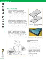
P E E N F O R M I N G<br />
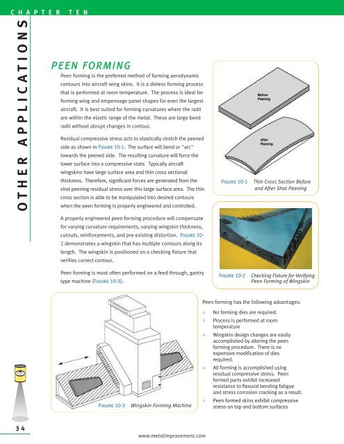
Peen <strong>forming</strong> is the preferred method of <strong>forming</strong> aerodynamic<br />
contours into aircraft wing skins. It is a dieless <strong>forming</strong> process<br />
that is performed at room temperature. The process is ideal for<br />
<strong>forming</strong> wing and empennage panel shapes for even the largest<br />
aircraft. It is best suited for <strong>forming</strong> curvatures where the radii<br />
are within the elastic range of the metal. These are large bend<br />
radii without abrupt changes in contour.<br />
Residual compressive stress acts to elastically stretch the <strong>peen</strong>ed<br />
side as shown in Figure 10-1. The surface will bend or "arc"<br />
towards the <strong>peen</strong>ed side. The resulting curvature will force the<br />
lower surface into a compressive state. Typically aircraft<br />
wingskins have large surface area and thin cross sectional<br />
thickness. Therefore, significant forces are generated from the<br />
shot <strong>peen</strong>ing residual stress over this large surface area. The thin<br />
cross section is able to be manipulated into desired contours<br />
when the <strong>peen</strong> <strong>forming</strong> is properly engineered and controlled.<br />
A properly engineered <strong>peen</strong> <strong>forming</strong> procedure will compensate<br />
for varying curvature requirements, varying wingskin thickness,<br />
cutouts, reinforcements, and pre-existing distortion. Figure 10-<br />
2 demonstrates a wingskin that has multiple contours along its<br />
length. The wingskin is positioned on a checking fixture that<br />
verifies correct contour.<br />
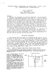
Peen <strong>forming</strong> is most often performed on a feed through, gantry<br />
type machine (Figure 10-3).<br />
Figure 10-3 Wingskin Forming Machine<br />
www.metalimprovement.com<br />
Figure 10-1 Thin Cross Section Before<br />
and After Shot Peening<br />
Figure 10-2 Checking Fixture for Verifying<br />
Peen Forming of Wingskin<br />
Peen <strong>forming</strong> has the following advantages:<br />
• No <strong>forming</strong> dies are required.<br />
• Process is performed at room<br />
temperature<br />
• Wingskin design changes are easily<br />
accomplished by altering the <strong>peen</strong><br />
<strong>forming</strong> procedure. There is no<br />
expensive modification of dies<br />
required.<br />
• All <strong>forming</strong> is accomplished using<br />
residual compressive stress. Peen<br />
formed parts exhibit increased<br />
resistance to flexural bending fatigue<br />
and stress corrosion cracking as a result.<br />
• Peen formed skins exhibit compressive<br />
stress on top and bottom surfaces
The majority of aircraft in production with aerodynamically<br />
formed aluminum alloy wingskins employ the <strong>peen</strong> <strong>forming</strong><br />
process.<br />
<strong>Metal</strong> <strong>Improvement</strong> <strong>Company</strong> has developed computer<br />
modeling techniques that allow feasibility studies of<br />
particular designs. The program takes three-dimensional<br />
engineering data and, based on the degree of compound<br />
curvature, calculates and illustrates the degree of <strong>peen</strong><br />
<strong>forming</strong> required. It also exports numerical data to define the<br />
Figure 10-4 Computer Modeling of<br />
<strong>peen</strong>ing that is required to obtain the curvatures. A<br />
significant advantage of these techniques is that MIC can<br />
Peen Forming Operation<br />
assist aircraft wing designers in the early stages of design. These techniques insure that the desired<br />
aerodynamic curvatures are met with economically beneficial manufacturing processes (Figure 10-4).<br />
C O N T O UR C O R R E C TION<br />
Shot <strong>peen</strong>ing utilizing <strong>peen</strong> <strong>forming</strong> techniques can be used to correct unfavorable geometry conditions.<br />
This is accomplished by shot <strong>peen</strong>ing selective locations of parts to utilize the surface loading from the<br />
induced compressive stress to restore the components to drawing requirements. Some examples are:<br />
• Driveshaft/crankshaft straightening<br />
• Roundness correction of ring shaped geometry<br />
• Aircraft wing stiffner adjustment<br />
• Welding distortion correction<br />
The <strong>peen</strong> <strong>forming</strong> process avoids the unfavorable tensile residual stresses produced by other straightening<br />
methods by inducing beneficial compressive residual stresses.<br />
W ORK H A R D E N I N G<br />
A number of materials and alloys have the potential to work harden through cold working. Shot <strong>peen</strong>ing<br />
can produce substantial increases in surface hardness for certain alloys of the following types of materials.<br />
• Stainless steel<br />
• Aluminum<br />
• Manganese stainless<br />
steels<br />
• Inconel<br />
• Stellite<br />
• Hastelloy<br />
This can be of particular value to<br />
parts that cannot be heat treated but<br />
require wear resistance on the<br />
surface. The following table<br />
illustrates examples of increases in<br />
surface hardness with shot <strong>peen</strong>ing.<br />
Material Before After Percent<br />
Shot Peen Shot Peen Increase<br />
Cartridge Brass 50 HRB 175 HRB 250<br />
304 Stainless 243 HV 423 HV 74<br />
316L Stainless 283 HV 398 HV 41<br />
Mn Stainless 23 HRC 55 HRC 139<br />
Inconel 625 300 HV 500 HV 67<br />
Stellite 42 HRC 54 HRC 29<br />
Hastalloy C 18 HRC 40 HRC 122 *<br />
Hastalloy C 25 HRC 45 HRC 80 **<br />
* Wrought condition ** Cast condition<br />
www.metalimprovement.com<br />
C H A P T E R T E N<br />
O THER APPL ICA T IONS<br />
35
C H A P T E R T E N<br />
O THER APPL ICA T IONS<br />
36<br />
S M<br />
P E E N T E X<br />
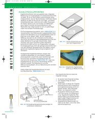
Controlled shot <strong>peen</strong>ing can also be used to deliver a number of<br />
different, aesthetically pleasing surface finishes. <strong>Metal</strong><br />
<strong>Improvement</strong> Co. stocks a great variety of media types and sizes.<br />
These media ranges from fine glass to large steel (and stainless<br />
steel) balls. Using a carefully controlled process, MIC is able to<br />
provide architectural finishes that are consistent, repeatable and<br />
more resistant to mechanical damage through work hardening.<br />
Shot <strong>peen</strong>ing finishes have been used to texture statues, handrails,<br />
gateway entrances, building facades, decorative ironwork, and<br />
numerous other applications for visual appeal. When selecting a<br />
decorative finish, MIC recommends sampling with several finishes<br />
for visual comparison. Figure 10-5 is a hand rail utilizing a chosen<br />
Peentexsm finish (left side of Figure 10-5) to dull the glare from the Figure 10-5 Before (right) and<br />
untextured finish (right side).<br />
A textured surface is able to hide surface scratches and flaws that<br />
After (left) Comparison<br />
of Peentex<br />
would otherwise be highly visible in a machined or ground surface. It is common to texture molds used for<br />
making plastics to hide surface defects. The texture on the mold surface will become a mirror image on the<br />
plastic part’s surface.<br />
sm<br />
E N G INEERED S U R F A C E S<br />
Engineered Surfaces are those that are textured to enhance surface performance. The following are<br />
potential surface applications achieved through shot <strong>peen</strong>ing.<br />
• In most cases a textured surface has a lower coefficient of (sliding) friction than<br />
a non-textured surface. This is because the surface contact area is reduced to<br />
the "peaks" of the shot <strong>peen</strong>ing dimples.<br />
• In some applications the "valleys" of the <strong>peen</strong>ing dimples offer lubricant<br />
retention that are not present in a smooth surface.<br />
• In some instances a non-directional textured surface is desired over a unidirectional<br />
machined/ground surface. This has proven effective in certain<br />
sealing applications<br />
• In certain mold applications, a textured surface has less vacuum effect resulting<br />
in desirable "release" properties.<br />
www.metalimprovement.com
A p p l i c a t i o n C a s e S t u d y<br />
PNEUMATIC CONVEYOR TUBING<br />
Pneumatic conveyor tubing can be up to 10 inches in<br />
diameter and is usually a stainless or aluminum alloy.<br />
It is used to transport plastic pellets at facilities<br />
consisting of molding companies or various<br />
production, blending and distribution sites.<br />
Transported pellets degrade when contact is made<br />
with internal piping surfaces. The velocity of the<br />
pellets results in friction, heat and lost production.<br />
Using a variation on Peentexsm that produces<br />
directional dimpling, MIC offers a directionally<br />
textured surface that significantly reduces the<br />
formation of fines, fluff and streamers that can<br />
Figure 10-6 Manufacturing Plant Utilizing<br />
Directionally Textured Pipe<br />
account for millions of pounds of lost and/or contaminated production each year. Directional shot <strong>peen</strong>ing has<br />
been found to be much superior to other internal treatments of the tubing, often is more economical and can<br />
Treatment<br />
Fines<br />
(grams/100,000 lb<br />
conveyed)<br />
be applied on-site. The directional surface finish has the<br />
added benefit of work hardening (when stainless or<br />
aluminum piping is used) extending the life of the<br />
Directional Shot Peened<br />
Smooth Mill Finish<br />
1,629<br />
4,886<br />
surface treatment.<br />
Spiral Groove Pipe 6,518<br />
The following are test results from six different internal<br />
Sandblasted Pipe 7,145<br />
pipe treatments. A lower value of fines per 100,000 lbs<br />
Polyurethane Coated<br />
Medium Scored Pipe<br />
7,215<br />
13,887<br />
conveyed is desirable. The directional shot <strong>peen</strong>ing<br />
resulted in one third of the fines of the next closest<br />
finish [Ref 10.1].<br />
A p p l i c a t i o n C a s e S t u d y<br />
FOOD INDUSTRY<br />
The cheese/dairy industry has found that the uniform dimples provide a surface<br />
that can advantageously replace other surface treatments. The textured surface<br />
from shot <strong>peen</strong>ing often has a lower coefficient of sliding friction that is necessary<br />
for cheese release properties on some food contact surfaces. The dimples act as<br />
lubricant reservoirs for fat or other substances allowing the cheese product to slide<br />
easier through the mold on the peaks of the shot <strong>peen</strong>ing dimples.<br />
Testing has shown that shot <strong>peen</strong>ed finishes meet or exceed necessary<br />
cleanability requirements in terms of microbial counts. This is due to the<br />
Figure 10-7 Single Cavity<br />
Cheese Mold<br />
rounded dimples that do not allow bacteria to collect and reproduce. Sharp<br />
impressions left from grit blasting, sand blasting or broken media have proved less cleanable and have a much<br />
greater tendency for bacteria to collect and reproduce [Ref 10.2]. Both glass beaded and stainless steel media<br />
have been used successfully in this application.<br />
Figure 10-7 depicts a single cavity cheese mold. MIC has successfully textured many geometries and<br />
sizes of cheese molds.<br />
www.metalimprovement.com<br />
C H A P T E R T E N<br />
O THER APPL ICA T IONS<br />
37
C H A P T E R T E N<br />
O THER APPL ICA T IONS<br />
38<br />
E X FOLIATION C ORROSION<br />
A large number of commercial aircraft are over 20 years old. Ultimately, the safety of older aircraft depends<br />
on the quality of the maintenance performed. An aged Boeing 737 explosively depressurized at 24,000 feet<br />
(7300 m) when 18 feet (6 m) of the fuselage skin ripped away. The cause of the failure was corrosion and<br />
metal fatigue [Ref 10.3].<br />
MIC has developed a process called Search Peeningsm to locate surface and slightly sub-surface corrosion.<br />
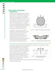
Exfoliation corrosion is a form of intergranular corrosion that occurs along aluminum grain boundaries. It is<br />
characterized by delamination of thin layers of aluminum with corrosion products between the layers. It is<br />
commonly found adjacent to fasteners due to galvanic<br />
action between dissimilar metals.<br />
The surface bulges outward as shown in Figure 10-8.<br />
In severe cases, the corrosion is subsurface.<br />
Once corrosion is present repairmen can manually<br />
remove it with sanding or other means. Shot <strong>peen</strong>ing is<br />
then applied to compensate for lost fatigue strength as<br />
a result of material removal. Additional sub-surface<br />
corrosion will appear as "blisters" exposed from the<br />
shot <strong>peen</strong>ing process. If additional corrosion is found, it<br />
is then removed and the Search Peeningsm process<br />
repeated until no more "blistering" occurs.<br />
MIC is capable of per<strong>forming</strong> the Search Peeningsm on-site at aircraft repair hangers. Critical areas of the<br />
aircraft are masked off by experienced shot <strong>peen</strong>ing technicians before beginning the process.<br />
P OROSITY S E A L I N G<br />
Surface porosity has long been a problem that has plagued the casting and powder metal industries.<br />
Irregularities in the material consistency at the surface may be improved by impacting the surface with shot<br />
<strong>peen</strong>ing media. By increasing the intensity (impact energy), <strong>peen</strong>ing can also be used to identify large,<br />
near-surface voids and delaminations.<br />
REFERENCES:<br />
10.1 Paulson; Effective Means for Reducing Formation of Fines and Streamers in Air Conveying Systems, Regional Technical<br />
Conference of the Society of Plastics Engineering; 1978, Flo-Tronics Division of Allied Industries; Houston, TX<br />
10.2 Steiner, Maragos, Bradley; Cleanability of Stainless Steel Surfaces With Various Finishes; Dairy, Food, and Environmental Sanitation, April 2000<br />
10.3 Eckersley; The Aging Aircraft Fleet, IMPACT; <strong>Metal</strong> <strong>Improvement</strong> Co.<br />
www.metalimprovement.com<br />
Figure 10-8 Exfoliation Corrosion