shot peening residual stress - Metal Improvement Company
shot peening residual stress - Metal Improvement Company
shot peening residual stress - Metal Improvement Company

You also want an ePaper? Increase the reach of your titles
YUMPU automatically turns print PDFs into web optimized ePapers that Google loves.
C H A P T E R O N E<br />
THEORY<br />
6<br />
T H E S H O T P E E N I N G<br />
P R O C E S S<br />
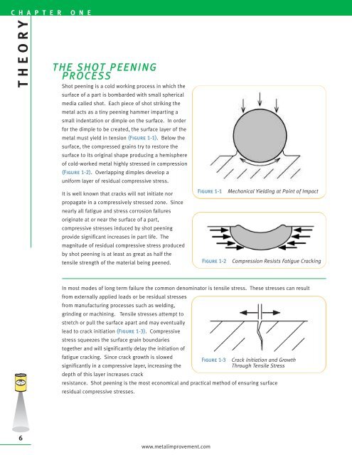
Shot <strong>peening</strong> is a cold working process in which the<br />
surface of a part is bombarded with small spherical<br />
media called <strong>shot</strong>. Each piece of <strong>shot</strong> striking the<br />
metal acts as a tiny <strong>peening</strong> hammer imparting a<br />
small indentation or dimple on the surface. In order<br />
for the dimple to be created, the surface layer of the<br />
metal must yield in tension (Figure 1-1). Below the<br />
surface, the compressed grains try to restore the<br />
surface to its original shape producing a hemisphere<br />
of cold-worked metal highly <strong>stress</strong>ed in compression<br />
(Figure 1-2). Overlapping dimples develop a<br />
uniform layer of <strong>residual</strong> compressive <strong>stress</strong>.<br />
It is well known that cracks will not initiate nor<br />
propagate in a compressively <strong>stress</strong>ed zone. Since<br />
nearly all fatigue and <strong>stress</strong> corrosion failures<br />
originate at or near the surface of a part,<br />
compressive <strong>stress</strong>es induced by <strong>shot</strong> <strong>peening</strong><br />
provide significant increases in part life. The<br />
magnitude of <strong>residual</strong> compressive <strong>stress</strong> produced<br />
by <strong>shot</strong> <strong>peening</strong> is at least as great as half the<br />
tensile strength of the material being peened.<br />
In most modes of long term failure the common denominator is tensile <strong>stress</strong>. These <strong>stress</strong>es can result<br />
from externally applied loads or be <strong>residual</strong> <strong>stress</strong>es<br />
from manufacturing processes such as welding,<br />
grinding or machining. Tensile <strong>stress</strong>es attempt to<br />
stretch or pull the surface apart and may eventually<br />
lead to crack initiation (Figure 1-3). Compressive<br />
<strong>stress</strong> squeezes the surface grain boundaries<br />
together and will significantly delay the initiation of<br />
fatigue cracking. Since crack growth is slowed<br />
Figure 1-3 Crack Initiation and Growth<br />
significantly in a compressive layer, increasing the<br />
Through Tensile Stress<br />
depth of this layer increases crack<br />
resistance. Shot <strong>peening</strong> is the most economical and practical method of ensuring surface<br />
<strong>residual</strong> compressive <strong>stress</strong>es.<br />
www.metalimprovement.com<br />
Figure 1-1 Mechanical Yielding at Point of Impact<br />
Figure 1-2 Compression Resists Fatigue Cracking
Shot <strong>peening</strong> is primarily used to combat metal fatigue. The following points pertain to metal fatigue and<br />
its application to the Typical Stress versus Load Cycles graph shown in Figure 1-4.<br />
• Fatigue loading<br />
consists of tens of<br />
thousands to millions<br />
of repetitive load<br />
cycles. The loads<br />
create applied tensile<br />
<strong>stress</strong> that attempt to<br />
stretch/pull the<br />
surface of the<br />
material apart.<br />
• A linear reduction in<br />
tensile <strong>stress</strong> results<br />
in an exponential<br />
increase in fatigue life<br />
(Number of Load<br />
Cycles). The graph<br />
(Figure 1-4) shows<br />
that a 38 ksi (262<br />
MPa) reduction in<br />
<strong>stress</strong> (32%) results in<br />
Figure 1-4 Typical Stress vs Load Cycles<br />
a 150,000 cycle life increase (300%).<br />
S H O T P E E N I N G<br />
R E S I D U A L<br />
S T R E S S<br />
The <strong>residual</strong> <strong>stress</strong> generated by<br />
<strong>shot</strong> <strong>peening</strong> is of a compressive<br />
nature. This compressive <strong>stress</strong><br />
offsets or lowers applied tensile<br />
<strong>stress</strong>. Quite simply, less (tensile)<br />
<strong>stress</strong> equates to longer part life.<br />
A typical <strong>shot</strong> <strong>peening</strong> <strong>stress</strong> profile<br />
is depicted in Figure 1-5.<br />
Maximum Compressive Stress –<br />
This is the maximum value of<br />
compressive <strong>stress</strong> induced. It is<br />
normally just below the surface.<br />
As the magnitude of the maximum<br />
Figure 1-5 Typical Shot Peening Residual Stress Profile<br />
compressive <strong>stress</strong> increases so does the resistance to fatigue cracking.<br />
Depth of Compressive Layer – This is the depth of the compressive layer resisting crack growth. The layer<br />
depth can be increased by increasing the <strong>peening</strong> impact energy. A deeper layer is generally desired for<br />
crack growth resistance.<br />
Surface Stress – This magnitude is usually less than the Maximum Compressive Stress.<br />
www.metalimprovement.com<br />
C H A P T E R O N E<br />
THEORY<br />
7
C H A P T E R O N E<br />
THEORY<br />
8<br />
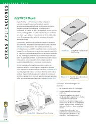
SUMMATION OF APPLIED<br />
AND RESIDUAL STRESS<br />
When a component is <strong>shot</strong> peened and subjected to<br />
an applied load, the surface of the component<br />
experiences the net <strong>stress</strong> from the applied load and<br />
<strong>shot</strong> <strong>peening</strong> <strong>residual</strong> <strong>stress</strong>. Figure 1-6 depicts a<br />
bar with a three-point load that creates a bending<br />
<strong>stress</strong> at the surface.<br />
The diagonal dashed line is the tensile <strong>stress</strong> created<br />
from the bending load. The curved dashed line is the<br />
(<strong>residual</strong>) compressive <strong>stress</strong> from <strong>shot</strong> <strong>peening</strong>.<br />
The solid line is the summation of the two showing a<br />
significant reduction of tensile <strong>stress</strong> at the surface.<br />
Shot <strong>peening</strong> is highly advantageous for the following two conditions.<br />
• Stress risers • High strength materials<br />
Stress risers may consist of radii, notches, cross holes, grooves, keyways, etc… Shot <strong>peening</strong> induces a<br />
high magnitude, localized compressive <strong>stress</strong> to offset the <strong>stress</strong> concentration factor created from these<br />
geometric changes.<br />
Shot <strong>peening</strong> is ideal for high strength materials. Compressive <strong>stress</strong> is directly correlated to a material’s<br />
tensile strength. The higher the tensile strength, the more compressive <strong>stress</strong> that can be induced. Higher<br />
strength materials have a more rigid crystal structure. This crystal lattice can withstand greater degrees of<br />
strain and consequently can store more <strong>residual</strong> <strong>stress</strong>.<br />
A p p l i c a t i o n C a s e S t u d y<br />
NASA LANGLEY CRACK GROWTH STUDY<br />
Engineers at NASA performed a study on crack growth rates of 2024-T3 aluminum with and without <strong>shot</strong><br />
<strong>peening</strong>. The samples were tested with an initial crack of 0.050" (1.27 mm) and then cycle tested to failure. It<br />
should be noted that the United States Air Force damage tolerance rogue flaw is 0.050" (1.27 mm).<br />
It was found that crack growth was significantly delayed when <strong>shot</strong> <strong>peening</strong> was included. As the following<br />
results demonstrate, at a 15 ksi (104 MPa) net <strong>stress</strong> condition the remaining life increased by 237%. At a 20<br />
ksi (138 MPa) net <strong>stress</strong> condition the remaining life increased by 81%.<br />
This test reflects conditions that are harsher than real world conditions. Real world conditions would generally<br />
not have initial flaws and should respond with better fatigue life improvements at these <strong>stress</strong> levels.<br />
NON-SHOT PEENED TEST RESULTS<br />
Net Number Average<br />
Stress Of Tests Life Cycles<br />
15 ksi 2 75,017<br />
20 3 26,029<br />
Note on sample preparation: A notch was placed in the surface via the EDM process. The samples were loaded<br />
in fatigue until the crack grew to ~ 0.050" (1.27 mm). If samples were <strong>shot</strong> peened, they were peened after the<br />
initial crack of 0.050" (1.27 mm) was generated. This was the starting point for the above results. [Ref 1.1]<br />
www.metalimprovement.com<br />
Figure 1-6 Resultant Stress in a Shot Peened<br />
Beam with an External Load Applied<br />
SHOT PEENED TEST RESULTS<br />
Net Number Average Percent<br />
Stress Of Tests Life Cycles Increase<br />
15 ksi 2 253,142 237%<br />
20 3 47,177 81%
D E P T H O F R E S I D U A L<br />
S T R E S S<br />
The depth of the compressive layer is influenced by<br />
variations in <strong>peening</strong> parameters and material<br />
hardness [Ref 1.2]. Figure 1-7 shows the relationship<br />
between the depth of the compressive layer and the<br />
<strong>shot</strong> <strong>peening</strong> intensity for five materials: steel 31 HRC,<br />
steel 52 HRC, steel 60 HRC, 2024 aluminum and<br />
titanium 6Al-4V. Depths for materials with other<br />
hardness values can be interpolated.<br />
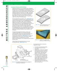
S H O T P E E N I N G M E D I A<br />
Media used for <strong>shot</strong> <strong>peening</strong> (see also Chapter 12)<br />
consists of small spheres of cast steel, conditioned<br />
cut wire (both carbon and stainless steel), ceramic or<br />
glass materials. Most often cast or wrought carbon<br />
steel is employed. Stainless steel media is used in<br />
Figure 1-7 Depth of Compression<br />
vs. Almen Arc Height<br />
applications where iron contamination on the part surface is of concern.<br />
Carbon steel cut wire, conditioned into near round<br />
shapes, is being specified more frequently due to its<br />
uniform, wrought consistency and great durability. It<br />
is available in various grades of hardness and in much<br />
tighter size ranges than cast steel <strong>shot</strong>.<br />
Glass beads are also used where iron contamination is<br />
of concern. They are generally smaller and lighter<br />
than other media and can be used to peen into sharp<br />
radii of threads and delicate parts where very low<br />
intensities are required.<br />
EFFECT O F S H OT<br />
HARDNESS<br />
It has been found that the hardness of the <strong>shot</strong> will<br />
influence the magnitude of compressive <strong>stress</strong><br />
(Figure 1-8). The <strong>peening</strong> media should be at least as<br />
hard or harder than the parts being peened unless<br />
Figure 1-8 Peening 1045 Steel (Rc 50+) [Ref 1.3]<br />
surface finish is a critical factor. For a large number of both ferrous and nonferrous parts, this criterion is<br />
met with regular hardness steel <strong>shot</strong> (45-52 HRC).<br />
The increased use of high strength, high hardness steels (50 HRC and above) is reflected in the use of<br />
special hardness <strong>shot</strong> (55-62 HRC).<br />
REFERENCES:<br />
1.1 Dubberly, Everett, Matthews, Prabhakaran, Newman; The Effects of Shot and Laser Peening on Crack Growth and Fatigue Life in 2024<br />
Aluminum Alloy and 4340 Steel, US Air Force Structural Integrity Conference, 2000<br />
1.2 Fuchs; Shot Peening Stress Profiles<br />
1.3 Lauchner, WESTEC Presentation March 1974, Northrup Corporation; Hawthorne, California<br />
www.metalimprovement.com<br />
C H A P T E R O N E<br />
THEORY<br />
9