AMS-S-13165 - Metal Improvement Company
AMS-S-13165 - Metal Improvement Company
AMS-S-13165 - Metal Improvement Company
Create successful ePaper yourself
Turn your PDF publications into a flip-book with our unique Google optimized e-Paper software.
<strong>AMS</strong>-S-<strong>13165</strong> SAE <strong>AMS</strong>-S-<strong>13165</strong><br />
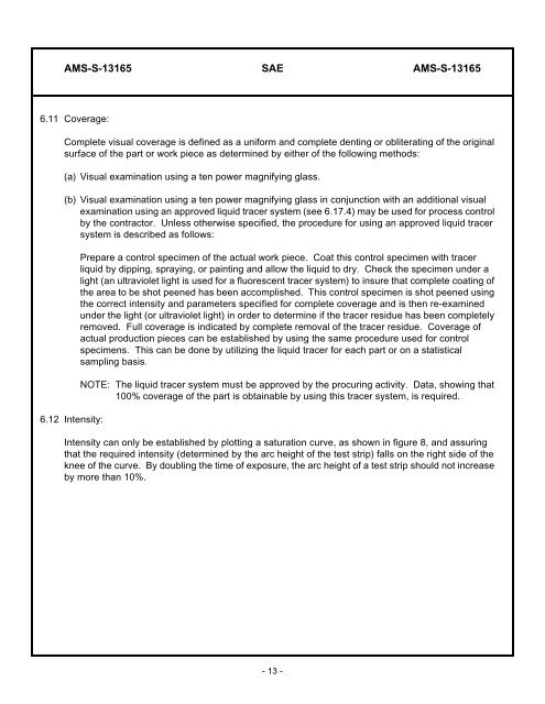
6.11 Coverage:<br />
Complete visual coverage is defined as a uniform and complete denting or obliterating of the original<br />
surface of the part or work piece as determined by either of the following methods:<br />
(a) Visual examination using a ten power magnifying glass.<br />
(b) Visual examination using a ten power magnifying glass in conjunction with an additional visual<br />
examination using an approved liquid tracer system (see 6.17.4) may be used for process control<br />
by the contractor. Unless otherwise specified, the procedure for using an approved liquid tracer<br />
system is described as follows:<br />
6.12 Intensity:<br />
Prepare a control specimen of the actual work piece. Coat this control specimen with tracer<br />
liquid by dipping, spraying, or painting and allow the liquid to dry. Check the specimen under a<br />
light (an ultraviolet light is used for a fluorescent tracer system) to insure that complete coating of<br />
the area to be shot peened has been accomplished. This control specimen is shot peened using<br />
the correct intensity and parameters specified for complete coverage and is then re-examined<br />
under the light (or ultraviolet light) in order to determine if the tracer residue has been completely<br />
removed. Full coverage is indicated by complete removal of the tracer residue. Coverage of<br />
actual production pieces can be established by using the same procedure used for control<br />
specimens. This can be done by utilizing the liquid tracer for each part or on a statistical<br />
sampling basis.<br />
NOTE: The liquid tracer system must be approved by the procuring activity. Data, showing that<br />
100% coverage of the part is obtainable by using this tracer system, is required.<br />
Intensity can only be established by plotting a saturation curve, as shown in figure 8, and assuring<br />
that the required intensity (determined by the arc height of the test strip) falls on the right side of the<br />
knee of the curve. By doubling the time of exposure, the arc height of a test strip should not increase<br />
by more than 10%.<br />
- 13 -


