Manual for the Design of Pipe Systems and Pumps - GEA ...
Manual for the Design of Pipe Systems and Pumps - GEA ...
Manual for the Design of Pipe Systems and Pumps - GEA ...

You also want an ePaper? Increase the reach of your titles
YUMPU automatically turns print PDFs into web optimized ePapers that Google loves.
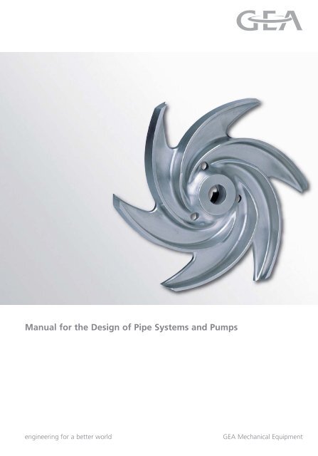
<strong>Manual</strong> <strong>for</strong> <strong>the</strong> <strong>Design</strong> <strong>of</strong> <strong>Pipe</strong> <strong>Systems</strong> <strong>and</strong> <strong>Pumps</strong><br />
engineering <strong>for</strong> a better world <strong>GEA</strong> Mechanical Equipment
2<br />
<strong>GEA</strong> Tuchenhagen
Table <strong>of</strong> Contents Page<br />
1 General<br />
Preface . . . . . . . . . . . . . . . . . . . . . . . . . . . . . . . . . . . . . . . . . . . . . . . . . . . .5<br />
Formula, Units, <strong>Design</strong>ation . . . . . . . . . . . . . . . . . . . . . . . . . . . . . . . . . . .6<br />
2 Introduction<br />
2.1 <strong>Pipe</strong> systems . . . . . . . . . . . . . . . . . . . . . . . . . . . . . . . . . . . . . . . . . . . . . . . .7<br />
2.2 Liquids . . . . . . . . . . . . . . . . . . . . . . . . . . . . . . . . . . . . . . . . . . . . . . . . . . . . .7<br />
2.3 Centrifugal pump or positive displacement pump . . . . . . . . . . . . . . . . .8<br />
2.4 Tuchenhagen ® VARIFLOW Programme . . . . . . . . . . . . . . . . . . . . . . . . . . .8<br />
2.5 Applications . . . . . . . . . . . . . . . . . . . . . . . . . . . . . . . . . . . . . . . . . . . . . . . .9<br />
2.6 Capacity range . . . . . . . . . . . . . . . . . . . . . . . . . . . . . . . . . . . . . . . . . . . . . .9<br />
2.7 <strong>Design</strong> . . . . . . . . . . . . . . . . . . . . . . . . . . . . . . . . . . . . . . . . . . . . . . . . . . . . .9<br />
2.8 Special features . . . . . . . . . . . . . . . . . . . . . . . . . . . . . . . . . . . . . . . . . . . .10<br />
2.9 Connection fittings . . . . . . . . . . . . . . . . . . . . . . . . . . . . . . . . . . . . . . . . .10<br />
2.10 Accessories <strong>and</strong> Options . . . . . . . . . . . . . . . . . . . . . . . . . . . . . . . . . . . . .10<br />
2.11 Self-priming centrifugal pumps . . . . . . . . . . . . . . . . . . . . . . . . . . . . . . .11<br />
2.12 Rotary lobe pumps . . . . . . . . . . . . . . . . . . . . . . . . . . . . . . . . . . . . . . . . . .11<br />
3 Physical Fundamentals<br />
3.1 Density . . . . . . . . . . . . . . . . . . . . . . . . . . . . . . . . . . . . . . . . . . . . . . . . . . .12<br />
3.2 Temperature . . . . . . . . . . . . . . . . . . . . . . . . . . . . . . . . . . . . . . . . . . . . . . .12<br />
3.3 Vapour pressure . . . . . . . . . . . . . . . . . . . . . . . . . . . . . . . . . . . . . . . . . . . .12<br />
3.4 Viscosity . . . . . . . . . . . . . . . . . . . . . . . . . . . . . . . . . . . . . . . . . . . . . . . . . .12<br />
3.5 Dynamic viscosity / Kinematice viscosity . . . . . . . . . . . . . . . . . . . . . . . .12<br />
3.6 Fluid behaviour . . . . . . . . . . . . . . . . . . . . . . . . . . . . . . . . . . . . . . . . . . . .13<br />
4 Hydraulic Fundamentals<br />
4.1 Pressure . . . . . . . . . . . . . . . . . . . . . . . . . . . . . . . . . . . . . . . . . . . . . . . . . . .14<br />
4.2 Atmospheric pressure . . . . . . . . . . . . . . . . . . . . . . . . . . . . . . . . . . . . . . .14<br />
4.3 Relation <strong>of</strong> pressure to elevation . . . . . . . . . . . . . . . . . . . . . . . . . . . . . .14<br />
4.4 Friction losses . . . . . . . . . . . . . . . . . . . . . . . . . . . . . . . . . . . . . . . . . . . . . .15<br />
4.5 Reynolds number . . . . . . . . . . . . . . . . . . . . . . . . . . . . . . . . . . . . . . . . . . .15<br />
5 Technical Fundamentals<br />
5.1 Installation . . . . . . . . . . . . . . . . . . . . . . . . . . . . . . . . . . . . . . . . . . . . . . . .16<br />
5.2 Connection . . . . . . . . . . . . . . . . . . . . . . . . . . . . . . . . . . . . . . . . . . . . . . . .16<br />
5.3 Suction pipe . . . . . . . . . . . . . . . . . . . . . . . . . . . . . . . . . . . . . . . . . . . . . . .17<br />
5.4 Delivery pipe . . . . . . . . . . . . . . . . . . . . . . . . . . . . . . . . . . . . . . . . . . . . . .17<br />
5.5 NPSH . . . . . . . . . . . . . . . . . . . . . . . . . . . . . . . . . . . . . . . . . . . . . . . . . . . .18<br />
5.6 Suction <strong>and</strong> delivery conditions . . . . . . . . . . . . . . . . . . . . . . . . . . . . . . .18<br />
5.7 Cavitation . . . . . . . . . . . . . . . . . . . . . . . . . . . . . . . . . . . . . . . . . . . . . . . . .19<br />
3<br />
<strong>GEA</strong> Tuchenhagen
5.8 Q-H characteristic diagram . . . . . . . . . . . . . . . . . . . . . . . . . . . . . . . . . . . .20<br />
5.9 Flow rate . . . . . . . . . . . . . . . . . . . . . . . . . . . . . . . . . . . . . . . . . . . . . . . . . . .21<br />
5.10 Flow head . . . . . . . . . . . . . . . . . . . . . . . . . . . . . . . . . . . . . . . . . . . . . . . . . . .21<br />
5.11 Plant charcteristic curve . . . . . . . . . . . . . . . . . . . . . . . . . . . . . . . . . . . . . . . .21<br />
5.12 Operating point . . . . . . . . . . . . . . . . . . . . . . . . . . . . . . . . . . . . . . . . . . . . . .21<br />
5.13 Pressure drops . . . . . . . . . . . . . . . . . . . . . . . . . . . . . . . . . . . . . . . . . . . . . . .22<br />
5.14 Theoretical calculation example . . . . . . . . . . . . . . . . . . . . . . . . . . . . . . . . .22<br />
6 <strong>Design</strong> <strong>of</strong> Centrifugal <strong>Pumps</strong><br />
6.1 Practical calculation example . . . . . . . . . . . . . . . . . . . . . . . . . . . . . . . . . . .24<br />
6.1.1 Calculation . . . . . . . . . . . . . . . . . . . . . . . . . . . . . . . . . . . . . . . . . . . . . . . . . .24<br />
6.1.2 Explanations . . . . . . . . . . . . . . . . . . . . . . . . . . . . . . . . . . . . . . . . . . . . . . . . .25<br />
6.1.3 Calculation <strong>of</strong> <strong>the</strong> NPSH . . . . . . . . . . . . . . . . . . . . . . . . . . . . . . . . . . . . . . .25<br />
6.2 Characteristic curve interpretation . . . . . . . . . . . . . . . . . . . . . . . . . . . . . . .26<br />
6.3 Modification . . . . . . . . . . . . . . . . . . . . . . . . . . . . . . . . . . . . . . . . . . . . . . . . .28<br />
6.3.1 Throttling . . . . . . . . . . . . . . . . . . . . . . . . . . . . . . . . . . . . . . . . . . . . . . . . . . .28<br />
6.3.2 Changing <strong>the</strong> speed . . . . . . . . . . . . . . . . . . . . . . . . . . . . . . . . . . . . . . . . . . .28<br />
6.3.3 Reducing <strong>the</strong> impeller size . . . . . . . . . . . . . . . . . . . . . . . . . . . . . . . . . . . . .29<br />
6.3.4 Operation in parallel . . . . . . . . . . . . . . . . . . . . . . . . . . . . . . . . . . . . . . . . . .29<br />
6.3.5 Operation in series . . . . . . . . . . . . . . . . . . . . . . . . . . . . . . . . . . . . . . . . . . . .29<br />
6.4 Pumping <strong>of</strong> viscous media . . . . . . . . . . . . . . . . . . . . . . . . . . . . . . . . . . . . .30<br />
6.4.1 Correction <strong>for</strong> high viscosities . . . . . . . . . . . . . . . . . . . . . . . . . . . . . . . . . .30<br />
6.4.2 Calculation <strong>of</strong> <strong>the</strong> correction factors . . . . . . . . . . . . . . . . . . . . . . . . . . . . .31<br />
7 <strong>Design</strong> <strong>of</strong> Rotary Lobe <strong>Pumps</strong><br />
7.1 Fundamentals . . . . . . . . . . . . . . . . . . . . . . . . . . . . . . . . . . . . . . . . . . . . . . . .32<br />
7.2 Pump rating conditions . . . . . . . . . . . . . . . . . . . . . . . . . . . . . . . . . . . . . . . .32<br />
7.3 Example . . . . . . . . . . . . . . . . . . . . . . . . . . . . . . . . . . . . . . . . . . . . . . . . . . . .33<br />
7.4 Rating <strong>the</strong> pump . . . . . . . . . . . . . . . . . . . . . . . . . . . . . . . . . . . . . . . . . . . . .34<br />
7.5 Result . . . . . . . . . . . . . . . . . . . . . . . . . . . . . . . . . . . . . . . . . . . . . . . . . . . . . .35<br />
8 Annex<br />
8.1 Diagram <strong>for</strong> <strong>the</strong> calculation <strong>of</strong> pressure drops . . . . . . . . . . . . . . . . . . . . .36<br />
8.2 Pressure drops <strong>of</strong> fittings in metre equivalent pipe length . . . . . . . . . . .37<br />
8.3 Pressure drops <strong>of</strong> valves in metre equivalent pipe length . . . . . . . . . . . .37<br />
8.4 Vapour pressure table <strong>for</strong> water . . . . . . . . . . . . . . . . . . . . . . . . . . . . . . . .39<br />
8.5 Pressure drops depending on viscosity . . . . . . . . . . . . . . . . . . . . . . . . . . . .40<br />
8.6 SI - Units . . . . . . . . . . . . . . . . . . . . . . . . . . . . . . . . . . . . . . . . . . . . . . . . . . . .45<br />
8.7 Conversion table <strong>of</strong> <strong>for</strong>eign units . . . . . . . . . . . . . . . . . . . . . . . . . . . . . . . .46<br />
8.8 Viscosity table . . . . . . . . . . . . . . . . . . . . . . . . . . . . . . . . . . . . . . . . . . . . . . . .47<br />
8.9 Mechanical seals . . . . . . . . . . . . . . . . . . . . . . . . . . . . . . . . . . . . . . . . . . . . .49<br />
8.10 Pump data sheet . . . . . . . . . . . . . . . . . . . . . . . . . . . . . . . . . . . . . . . . . . . . .51<br />
8.11 Assembly instructions . . . . . . . . . . . . . . . . . . . . . . . . . . . . . . . . . . . . . . . . .52<br />
4<br />
<strong>GEA</strong> Tuchenhagen<br />
Page
Preface<br />
Archimedes - <strong>the</strong> ingenious scientist <strong>of</strong> <strong>the</strong> ancient world -<br />
recognized <strong>the</strong> functionality <strong>of</strong> pumps as early as in <strong>the</strong> middle <strong>of</strong><br />
<strong>the</strong> 3rd cent. B.C. Through <strong>the</strong> invention <strong>of</strong> <strong>the</strong> Archimedean screw,<br />
<strong>the</strong> irrigation <strong>of</strong> <strong>the</strong> fields became much more effective.<br />
2200 years later <strong>GEA</strong> Tuchenhagen is building high-tech pumps <strong>for</strong> hygie-<br />
nic process technology giving <strong>the</strong> process lines <strong>the</strong> optimal impetus.<br />
Selecting <strong>the</strong> right pump to serve <strong>the</strong> purpose is not always that easy <strong>and</strong><br />
requires special knowledge. <strong>GEA</strong> Tuchenhagen has set up this <strong>Manual</strong> <strong>for</strong><br />
giving support in finding out <strong>the</strong> optimal pump design. Special attention<br />
was given to produce a <strong>Manual</strong> that is interesting <strong>and</strong> in<strong>for</strong>mative <strong>for</strong><br />
5<br />
<strong>GEA</strong> Tuchenhagen<br />
everybody, from <strong>the</strong> competent engineer to<br />
<strong>the</strong> layman.<br />
The contents is self-explanatory<br />
<strong>and</strong> built up one after <strong>the</strong><br />
o<strong>the</strong>r. Simplifications were<br />
partly accepted <strong>and</strong> pr<strong>of</strong>o-<br />
und <strong>the</strong>ories dispensed<br />
with. We hope that this<br />
<strong>Manual</strong> will give you an<br />
extended comprehension<br />
<strong>of</strong> this subject <strong>and</strong> will<br />
help you solving any<br />
problems that might occur.
Formula, Units, <strong>Design</strong>ation<br />
Formula <strong>Design</strong>ation SI - Unit<br />
B Operating point -<br />
D Impeller diameter mm<br />
DN or d Nominal width <strong>of</strong> <strong>the</strong> pipe or pump port mm<br />
g Acceleration <strong>of</strong> <strong>the</strong> fall = 9.81 m/s 2 m/s 2<br />
H Flow head m<br />
H A Flow head <strong>of</strong> <strong>the</strong> system m<br />
H geo Geodetic flow head m<br />
H s,geo Geodetic suction head m<br />
H d,geo Geodetic pressure head m<br />
H z,geo Static suction head m<br />
H z Flow head viscous medium m<br />
H v Pressure drops m<br />
H v,s Pressure drops, suction side m<br />
H v,d Pressure drops, delivery side m<br />
K H Correction factor <strong>for</strong> <strong>the</strong> flow head -<br />
K Q Correction factor <strong>for</strong> <strong>the</strong> flow rate -<br />
K h Correction factor <strong>for</strong> <strong>the</strong> efficiency -<br />
k <strong>Pipe</strong> roughness mm<br />
l <strong>Pipe</strong> length m<br />
n Speed rpm.<br />
NPSH req. NPSH (pump) m<br />
NPSH avl NPSH (system) m<br />
P Power consumption kW<br />
P z Power consumption viscous medium kW<br />
p Pressure bar<br />
p a Pressure at <strong>the</strong> outlet cross section <strong>of</strong> a system bar<br />
p b Air pressure / ambient pressure bar<br />
p D Vapour pressure <strong>of</strong> pumped liquids bar<br />
p e Pressure at <strong>the</strong> inlet cross section <strong>of</strong> a system bar<br />
Q Flow rate m 3 /h<br />
Q z Flow rate viscous medium m 3 /h<br />
Re Reynolds number -<br />
v Flow speed m/s<br />
v a Flow speed at <strong>the</strong> outlet cross section <strong>of</strong> a system m/s<br />
v e Flow speed at <strong>the</strong> inlet cross section <strong>of</strong> a system m/s<br />
ζ (Zeta) Loss value -<br />
η (Eta) Efficiency <strong>of</strong> <strong>the</strong> pump -<br />
η z (Eta) Efficiency <strong>of</strong> <strong>the</strong> pump <strong>for</strong> viscous medium -<br />
λ (Lambda) Efficiency value -<br />
ν (Ny) Kinematic viscosity mm 2 /s<br />
η (Eta) Dynamic viscosity Pa s<br />
ρ (Rho) Density t/m 3<br />
6<br />
<strong>GEA</strong> Tuchenhagen
2 Introduction<br />
2.1 <strong>Pipe</strong><br />
systems<br />
2.2 Liquids<br />
The requirements made on process plants steadily increase, both regarding <strong>the</strong><br />
quality <strong>of</strong> <strong>the</strong> products <strong>and</strong> <strong>the</strong> pr<strong>of</strong>itability <strong>of</strong> <strong>the</strong> processes. Making liquids flow solely<br />
due to <strong>the</strong> earth’s gravitational <strong>for</strong>ce is today unthinkable. Liquids are <strong>for</strong>ced through<br />
pipes, valves, heat exchangers, filters <strong>and</strong> o<strong>the</strong>r components, <strong>and</strong> all <strong>of</strong> <strong>the</strong>m cause an<br />
increased resistance <strong>of</strong> flow <strong>and</strong> thus pressure drops.<br />
<strong>Pumps</strong> are <strong>the</strong>re<strong>for</strong>e installed in different sections <strong>of</strong> a plant. The choice <strong>of</strong> <strong>the</strong> right pump at<br />
<strong>the</strong> right place is crucial <strong>and</strong> will be responsible <strong>for</strong> <strong>the</strong> success or failure <strong>of</strong> <strong>the</strong> process.<br />
The following factors should be taken into consideration:<br />
1. Installation <strong>of</strong> <strong>the</strong> pump<br />
2. Suction <strong>and</strong> delivery pipes<br />
3. The pump type chosen must correspond to product viscosity, product density,<br />
temperature, system pressure, material <strong>of</strong> <strong>the</strong> pump, shearing tendency <strong>of</strong> <strong>the</strong><br />
product etc.<br />
4. The pump size must con<strong>for</strong>m to <strong>the</strong> flow rate, pressure, speed,<br />
suction conditons etc.<br />
As a manufacturer <strong>and</strong> supplier <strong>of</strong> centrifugal pumps <strong>and</strong> positive displacement pumps we<br />
<strong>of</strong>fer <strong>the</strong> optimum <strong>for</strong> both applications.<br />
Generally spoken, <strong>the</strong> pump is a device that conveys a certain volume <strong>of</strong> a specific liquid<br />
from point A to point B within a unit <strong>of</strong> time.<br />
For optimal pumping, it is essential be<strong>for</strong>e selecting <strong>the</strong> pump to have examined <strong>the</strong> pipe<br />
system very carefully as well as <strong>the</strong> liquid to be conveyed.<br />
<strong>Pipe</strong> systems have always special characterstics <strong>and</strong> must be closely inspected <strong>for</strong> <strong>the</strong> choice<br />
<strong>of</strong> <strong>the</strong> appropriate pump. Details as to considerations <strong>of</strong> pipe systems are given in Chapter 6,<br />
"<strong>Design</strong> <strong>of</strong> pumps".<br />
Each liquid possesses diverse characteristics that may influence not only <strong>the</strong> choice <strong>of</strong> <strong>the</strong><br />
pump, but also its configuration such as <strong>the</strong> type <strong>of</strong> <strong>the</strong> mechanical seal or <strong>the</strong> motor.<br />
Fundamental characteristics in this respect are:<br />
• Viscosity (friction losses)<br />
• Corrodibility (corrosion)<br />
• Abrasion<br />
• Temperature (cavitation)<br />
• Density<br />
• Chemical reaction (gasket material)<br />
7<br />
<strong>GEA</strong> Tuchenhagen
2.3 Centrifugal<br />
or positive<br />
displacement<br />
pump<br />
2.4 <strong>GEA</strong><br />
Tuchenhagen ®<br />
VARIFLOW<br />
Programme<br />
Besides <strong>the</strong>se fundamental criteria, some liquids need special care during <strong>the</strong> transport.<br />
The main reasons are:<br />
• The product is sensitive to shearing <strong>and</strong> could get damaged, such as yoghurt or yoghurt<br />
with fruit pulp<br />
• The liquid must be processed under highest hygienic conditions as practised in <strong>the</strong><br />
pharmaceutical industry or food industry<br />
• The product is very expensive or toxic <strong>and</strong> requires hermetically closed transport paths as<br />
used in <strong>the</strong> chemical or pharmaceutical industry.<br />
Experience <strong>of</strong> many years in research <strong>and</strong> development <strong>of</strong> pumps enables<br />
<strong>GEA</strong> Tuchenhagen today to <strong>of</strong>fer a wide range <strong>of</strong> hygienic pumps <strong>for</strong> <strong>the</strong> food <strong>and</strong><br />
beverage industry as well as <strong>the</strong> pharmaceutical <strong>and</strong> chemical industry.<br />
We <strong>of</strong>fer efficient, operationally safe, low-noise pumps <strong>for</strong> your processes <strong>and</strong> this <strong>Manual</strong><br />
shall help you to make <strong>the</strong> right choice.<br />
The first step on <strong>the</strong> way to <strong>the</strong> optimal pump is <strong>the</strong> selection between a centrifugal pump or<br />
a positive displacement pump. The difference lies on one h<strong>and</strong> in <strong>the</strong> prin-ciple <strong>of</strong> transporting<br />
<strong>the</strong> liquid <strong>and</strong> on <strong>the</strong> o<strong>the</strong>r h<strong>and</strong> in <strong>the</strong> pumping characteristic. There are two types <strong>of</strong><br />
centrifugal pumps: "non-self priming" <strong>and</strong> "selfpriming".<br />
Centrifugal pumps are <strong>for</strong> most <strong>of</strong> <strong>the</strong> cases <strong>the</strong> right choice, because <strong>the</strong>y are easily installed,<br />
adapted to different operating parameters <strong>and</strong> easily cleaned. Competitive purchase costs <strong>and</strong><br />
reliable transport <strong>for</strong> most <strong>of</strong> <strong>the</strong> liquids are <strong>the</strong> reason <strong>for</strong> <strong>the</strong>ir steady presence in process<br />
plants. Restrictions must be expected in <strong>the</strong> following cases:<br />
• with viscous media <strong>the</strong> capacity limit is quickly reached,<br />
• <strong>the</strong> use is also restricted with media being sensitive to shearing,<br />
• with abbrasive liquids <strong>the</strong> service life <strong>of</strong> <strong>the</strong> centrifugal pump is reduced<br />
because <strong>of</strong> earlier wear.<br />
The <strong>GEA</strong> Tuchenhagen ® -VARIFLOW Pump Programme con<strong>for</strong>ms to today’s requirements<br />
made on cleanability, gentle product h<strong>and</strong>ling, efficiency <strong>and</strong> ease <strong>of</strong> maintenance.<br />
The different technical innovations made on <strong>the</strong> pumps <strong>for</strong> <strong>the</strong> optimization <strong>of</strong><br />
cleanability have been EHEDG-certified.<br />
8<br />
<strong>GEA</strong> Tuchenhagen
2.5 Applications<br />
2.6 Capacity<br />
range<br />
2.7 <strong>Design</strong><br />
The new <strong>GEA</strong> Tuchenhagen ® -VARIFLOW pumps are preferably used in <strong>the</strong> brewing <strong>and</strong><br />
beverage indus try as well as in dairies <strong>and</strong> in process plants <strong>for</strong> chemical, pharmaceu tical <strong>and</strong><br />
health care products where highest hygienic st<strong>and</strong>ards are set. They are used in <strong>the</strong>se industries<br />
mainly as transfer pumps, ClP supply pumps <strong>and</strong> booster pumps.<br />
Fig. 1 - <strong>GEA</strong> Tuchenhagen ® -VARIFLOW Centrifugal Pump, Type TP<br />
The <strong>GEA</strong> Tuchenhagen ® -VARIFLOW series is designed <strong>for</strong> flow rates up to 220 m 3/h <strong>and</strong><br />
flow heads up to 92 m liquid column<br />
<strong>Pumps</strong> <strong>of</strong> <strong>the</strong> <strong>GEA</strong> Tuchenhagen ® -VARIFLOW series are non-self priming,<br />
one-stage centrifugal pum ps with single bent vanes.<br />
• All pumps <strong>of</strong> <strong>the</strong> <strong>GEA</strong> Tuchenhagen ® -VARIFLOW series are driven by st<strong>and</strong>ard motors<br />
<strong>of</strong> type IM B35.<br />
• A spiral housing is used as guiding device <strong>for</strong> <strong>the</strong> <strong>GEA</strong> Tuchenhagen ® -VARIFLOW series .<br />
It provides high efficiency so that <strong>the</strong> operating costs can be lowered.<br />
Besides high efficiency, special emphasis has been given to gentle product h<strong>and</strong>ling.<br />
After <strong>the</strong> product leaves <strong>the</strong> impeller, it is gently discharged in flow direction via <strong>the</strong><br />
spiral housing.<br />
• <strong>GEA</strong> Tuchenhagen ® -VARIFLOW pumps have been certified according to<br />
EHEDG <strong>and</strong> 3A.<br />
9<br />
<strong>GEA</strong> Tuchenhagen
2.8 Special<br />
features<br />
2.9 Connection<br />
fittings<br />
2.10 Accessories<br />
<strong>and</strong> Options<br />
Main components:<br />
Pump cover, impeller, pump housing<br />
lantern, shaft <strong>and</strong> motor<br />
Pump<br />
cover<br />
Impeller<br />
Fig 2 - <strong>GEA</strong> Tuchenhagen ® -VARIFLOW, TP<br />
• All parts in stainless steel, product wetted components are made <strong>of</strong><br />
AISI 316L (1.4404).<br />
• High efficiency<br />
• Gentle product h<strong>and</strong>ling<br />
• Low noise<br />
• Ease <strong>of</strong> maintenance<br />
• Excellent hygienic properties.<br />
• Threaded joint as per DIN 11851 (St<strong>and</strong>ard)<br />
• VARIVENT ® flange connection<br />
• Aseptic flanges as per DIN 11864-2<br />
• Aseptic union as per DIN 11864-1<br />
• O<strong>the</strong>r marketable connections according to BS, SMS, RJT, Tri-Clamp<br />
• Metric <strong>and</strong> Inch diameters<br />
• Mechanical seals in different materials Carbon/Silicon carbide or<br />
Silicon carbide/Silicon carbide<br />
• Different designs as single acting, single with flush (Quench) or double acting<br />
• FDA approved s<strong>of</strong>t seals: EPDM <strong>and</strong> FPM<br />
• Stainless steel protection hood, mobile baseframe, drainage valve<br />
• Adjustable calotte type feet frame<br />
• Inducer<br />
10<br />
<strong>GEA</strong> Tuchenhagen<br />
Pump<br />
housing<br />
Mech.<br />
shaft seal<br />
One-part lantern<br />
Sealing according to <strong>the</strong><br />
VARIVENT ® principle<br />
Motor<br />
Pump shaft<br />
without<br />
fea<strong>the</strong>r key
2.11 Self-priming<br />
centrifugal<br />
pumps<br />
2.12 Rotary lobe<br />
pumps<br />
The <strong>GEA</strong> Tuchenhagen self-priming pump <strong>of</strong> <strong>the</strong> TPS series are used <strong>for</strong> conveying<br />
aggressive, clean liquids that are free <strong>of</strong> abrasive constituents. <strong>Pumps</strong> <strong>of</strong> <strong>the</strong> TPS series are<br />
horizontal, self-priming pumps. They st<strong>and</strong> out by <strong>the</strong>ir sturdy construction <strong>and</strong> high<br />
operational reliability <strong>and</strong> are preferably used in <strong>the</strong> food processing <strong>and</strong> luxury<br />
food industry as a CIP return pump.<br />
Fig. 3 - Self-priming centrifugal pump, type TPS<br />
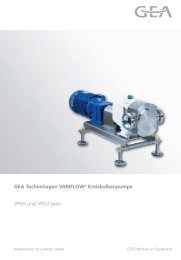
<strong>GEA</strong> Tuchenhagen rotary lobe pumps <strong>of</strong> <strong>the</strong> VPSH <strong>and</strong> VPSU series are used whenever<br />
viscous, sensitive or solids-containing liquids must be gently transferred.<br />
Type VPSH is used in hygienic applications <strong>of</strong> all kinds.<br />
Type VPSU has been designed especially <strong>for</strong> high aseptic requirements that are st<strong>and</strong>ard in<br />
sterile areas.<br />
The special design <strong>of</strong> <strong>the</strong> Skimitar rotors <strong>and</strong> <strong>the</strong> pump’s design enable <strong>the</strong> pump to convey a<br />
wide range <strong>of</strong> media: from low-viscous media to products with a viscosity <strong>of</strong><br />
up to 1,000,000 mPas or even media with suspended solids.<br />
Due to <strong>the</strong> shape <strong>of</strong> <strong>the</strong> Skimitar rotors, a particularly high efficiency is achieved.<br />
Fig. 4 - Rotary lobe pump VPSH<br />
11<br />
<strong>GEA</strong> Tuchenhagen
3 Physical Fundamentals<br />
3.1 Density<br />
3.2 Temperature<br />
3.3 Vapour<br />
pressure<br />
3.4 Viscosity<br />
3.5 Dynamic <strong>and</strong><br />
kinematic<br />
viscosity<br />
Fluids - a subject matter <strong>of</strong> this <strong>Manual</strong> - include liquids, gases <strong>and</strong> mixtures <strong>of</strong> liquids,<br />
solids <strong>and</strong> gases. All <strong>the</strong>se fluids have specific characteristics that will be explained in this<br />
chapter.<br />
Density (ρ = Rho) - <strong>for</strong>mer specific weight - <strong>of</strong> a fluid is its weight per unit volume,<br />
usually expressed in units <strong>of</strong> grams per cubic centimeter (g/cm 3 ).<br />
Example: If weight is 80 g in a cube <strong>of</strong> one cubic centimeter, <strong>the</strong> density <strong>of</strong> <strong>the</strong> medium is<br />
80 g/cm 3 . The density <strong>of</strong> a fluid changes with <strong>the</strong> temperature..<br />
Temperature (t) is usually expressed in units <strong>of</strong> degrees centigrade (°C) or Kelvin (K). The<br />
temperature <strong>of</strong> a fluid at <strong>the</strong> pump inlet is <strong>of</strong> great importance, because it has a strong effect<br />
on <strong>the</strong> suction characteristic <strong>of</strong> a pump.<br />
The vapour pressure (p D) <strong>of</strong> a liquid is <strong>the</strong> absolute pressure at a given temperature at which<br />
<strong>the</strong> liquid will change to vapour. Each liquid has its own specific point where it starts to<br />
evaporate. Vapour pressure is expressed in bar (absolute).<br />
Viscosity <strong>of</strong> a medium is a measure <strong>of</strong> its tendency to resist shearing <strong>for</strong>ce.<br />
Media <strong>of</strong> high viscosity require a greater <strong>for</strong>ce to shear at a given rate than fluids <strong>of</strong><br />
low viscositiy.<br />
One has to distinguish between kinematic viscosity (ν = Ny) <strong>and</strong> dynamic viscosity<br />
(η = Eta). Centipoise (cP) is <strong>the</strong> traditional unit <strong>for</strong> expressing dynamic viscosity.<br />
Centistokes (cSt) or Millipascal (mPa) express <strong>the</strong> kinematic viscosity.<br />
Ratio: kinematic viscosity =<br />
Viscosity is not constant <strong>and</strong> thus depending on external factors. The viscous behaviour <strong>of</strong><br />
media is more clearly expresed in effective viscosity or shearing <strong>for</strong>ce. The behaviour <strong>of</strong> viscous<br />
fluids varies.<br />
One distinguishes between Newtonian <strong>and</strong> Non-Newtonian fluids.<br />
12<br />
<strong>GEA</strong> Tuchenhagen<br />
dynamic viscosity<br />
density
3.6 Fluid<br />
behaviour<br />
The flow curve is a diagram which shows <strong>the</strong> correlation between viscosity (η) <strong>and</strong> <strong>the</strong> shear<br />
rate (D). The shear rate is calculated from <strong>the</strong> ratio between <strong>the</strong> difference in flow velocity <strong>of</strong><br />
two adjacent fluid layers <strong>and</strong> <strong>the</strong>ir distance to eacho<strong>the</strong>r.<br />
The flow curve <strong>for</strong> an ideal fluid is a straight line. This means constant viscosity at all shear<br />
rates. All fluids <strong>of</strong> this characteristic are "Newtonian fluids". Examples are water, mineral oils,<br />
syrup, resins.<br />
Fig. 6 - Flow curves<br />
Fluids that change <strong>the</strong>ir viscosity in dependence <strong>of</strong> <strong>the</strong> shear rate are called<br />
"Non-Newtonian fluids". In practice, a very high percentage <strong>of</strong> fluids pumped are<br />
non-Newtonian <strong>and</strong> can be differentiated as follows:<br />
Intrinsically viscous fluids<br />
Viscosity decreases as <strong>the</strong> shear rate increases at high initial <strong>for</strong>ce. This means from <strong>the</strong><br />
technical point <strong>of</strong> view that <strong>the</strong> energy after <strong>the</strong> initial <strong>for</strong>ce needed <strong>for</strong> <strong>the</strong> flow rate can be<br />
reduced. Typical fluids with above described characteristics are a.o. gels, Latex, lotions.<br />
Dilatent fluids<br />
Viscosity increases as <strong>the</strong> shear rate increases. Example: pulp, sugar mixture<br />
Thixotropic fluids<br />
Viscosity decreases with strong shear rate (I) <strong>and</strong> increases again as <strong>the</strong> shear rate decreases (II).<br />
The ascending curve is however not identical to <strong>the</strong> descending curve. Typical fluids are a.o.<br />
soap, Ketchup, glue, peanut butter<br />
Viscosity<br />
Δy<br />
Fig. 5 - Shear rate<br />
Viscosity<br />
II<br />
Shear rate<br />
Shear rate<br />
Fig. 7 - Thixotropic fluids<br />
I<br />
Δv<br />
13<br />
<strong>GEA</strong> Tuchenhagen<br />
v<br />
3 1 Newtonian<br />
fluids<br />
1<br />
2<br />
D = Δv<br />
Δy<br />
2 Intrinsically<br />
viscous fluids<br />
3 Dilatent fluids
4 Hydraulic Fundamentals<br />
4.1 Pressure<br />
4.2 Atmospheric<br />
pressure<br />
4.3 Relation <strong>of</strong><br />
pressure to<br />
elevation<br />
<strong>Pumps</strong> shall produce pressure. Fluids are conveyed over a certain distance by kinetic energy<br />
produced by <strong>the</strong> pump.<br />
The basic definition <strong>of</strong> pressure (p) is <strong>the</strong> <strong>for</strong>ce per unit area. It is expressed in this <strong>Manual</strong> in<br />
Newton per square meter (N/m2 = Pa).<br />
1 bar = 105 = 105 N<br />
Pa<br />
Atmospheric pressure is <strong>the</strong> <strong>for</strong>ce exerted on a unit area by <strong>the</strong> weight <strong>of</strong> <strong>the</strong> atmosphere. It<br />
depends on <strong>the</strong> height above sea level (see Fig. 8). At sea level <strong>the</strong> absolute pressure is<br />
approximately 1 bar = 10 5 N / m 2.<br />
Gage pressure uses atmospheric pressure as a zero reference <strong>and</strong> is <strong>the</strong>n measured in relation<br />
to atmospheric pressure. Absolute pressure is <strong>the</strong> atmospheric pressure plus <strong>the</strong> relative<br />
pressure.<br />
Height above sea level<br />
m<br />
Air pressure pb bar<br />
Boiling temperature<br />
°C<br />
0<br />
200<br />
1,013<br />
989<br />
100<br />
99<br />
500 955 98<br />
1,000 899 97<br />
2,000 795 93<br />
Fig. 8 - Influcence <strong>of</strong> <strong>the</strong> topographic height<br />
In a static liquid <strong>the</strong> pressure difference between any two points is in direct proportion to <strong>the</strong><br />
vertical distance between <strong>the</strong> two points only.<br />
The pressure difference is calculated by multiplying <strong>the</strong> vertical distance by density.<br />
In this <strong>Manual</strong> different pressures or pressure relevant terms are used. Here below are listed<br />
<strong>the</strong> main terms <strong>and</strong> <strong>the</strong>ir definitions:<br />
Static pressure Hydraulic pressure at a point in a fluid at rest.<br />
Friction loss Loss in pressure or energy due to friction losses in flow<br />
Dynamic pressure Energy in a fluid that occurs due to <strong>the</strong> flow velocity.<br />
Delivery pressure Sum <strong>of</strong> static <strong>and</strong> dynamic pressure increase.<br />
Delivery head Delivery pressure converted into m liquid column.<br />
Differential pressure Pressure between <strong>the</strong> initial <strong>and</strong> end point <strong>of</strong> <strong>the</strong> plant.<br />
14<br />
<strong>GEA</strong> Tuchenhagen<br />
m 2
4.4 Friction<br />
losses<br />
4.5 Reynolds<br />
number<br />
The occurance <strong>of</strong> friction losses in a pipe system is very complex <strong>and</strong> <strong>of</strong> essential importance<br />
when selecting <strong>the</strong> pump. Friction losses in components caused by <strong>the</strong> flow in <strong>the</strong> pipe<br />
system (laminar flow <strong>and</strong> turbulent flow) are specified by <strong>the</strong> pump manufacturer.<br />
There are two different types <strong>of</strong> flow<br />
Laminar flow is characterized by concentric layers moving in parallel down <strong>the</strong> length <strong>of</strong> <strong>the</strong><br />
pipe, whereby highest velocity is found in <strong>the</strong> centre <strong>of</strong> <strong>the</strong> pipe, decreasing along <strong>the</strong> pipe<br />
wall (see Fig. 9). Directly at <strong>the</strong> wall <strong>the</strong> velocity decreases down to zero. There is virtually no<br />
mixing between <strong>the</strong> layers. The friction loss is proportional to <strong>the</strong> length <strong>of</strong> <strong>the</strong> pipe, flow<br />
rate, pipe diameter <strong>and</strong> viscosity.<br />
Fig. 9 - Laminar flow<br />
In case <strong>of</strong> turbulent flow strong mixing takes place between <strong>the</strong> layers whereby <strong>the</strong><br />
<strong>the</strong> velocity <strong>of</strong> <strong>the</strong> turbulences is extremely high.<br />
Turbulent flow occurs mainly in low viscous fluids <strong>and</strong> is characterised by higher friction<br />
losses. The friction losses behave proportional to <strong>the</strong> length <strong>of</strong> <strong>the</strong> pipe, square flow rate,<br />
pipe diameter <strong>and</strong> viscosity.<br />
Fig. 10 - Turbulent flow<br />
In transition between laminar flow <strong>and</strong> turbulent flow <strong>the</strong>re is a multitude <strong>of</strong> so called<br />
„mixed flows“. They are characterised by a combination <strong>of</strong> properties <strong>of</strong> <strong>the</strong> turbulent flow<br />
<strong>and</strong> <strong>the</strong> laminar flow. For determination <strong>and</strong> simple computing <strong>of</strong> <strong>the</strong> specific characteristics<br />
<strong>the</strong> Reynolds number was introduced. This dimensionless number is <strong>the</strong> ratio <strong>of</strong> fluid<br />
velocity multiplied by pipe diameter, divided by kinematic fluid viscosity.<br />
Re = v x DN / ν Re = Reynolds number<br />
v = Fluid velocity (m/s)<br />
DN = <strong>Pipe</strong> diameter<br />
ν = Kinematic fluid viscosity<br />
General: Laminar flow - if Re < 2320<br />
Turbulent flow - if Re ≥ 2320<br />
15<br />
<strong>GEA</strong> Tuchenhagen
5 Technical Fundamentals<br />
5.1 Installation<br />
5.2 <strong>Pipe</strong><br />
connection<br />
This <strong>Manual</strong> helps carrying out <strong>the</strong> optimal design <strong>of</strong> centrifugal pumps. We show you<br />
how to proceed to find <strong>the</strong> right pump.<br />
Install <strong>the</strong> pump in close vicinity to <strong>the</strong> tank or to ano<strong>the</strong>r source from which <strong>the</strong> liquid will<br />
be pumped. Make sure that as few as possible valves <strong>and</strong> bends are integrated in <strong>the</strong> pump‘s<br />
suction pipe, in order to keep <strong>the</strong> pressure drop as low as possible. Sufficient space around<br />
<strong>the</strong> pump provides <strong>for</strong> easy maintenance work <strong>and</strong> inspection. <strong>Pumps</strong> equipped with a<br />
conventional base plate <strong>and</strong> motor base should be mounted on a steady foundation <strong>and</strong> be<br />
precisely aligned prior commissioning.<br />
<strong>GEA</strong> Tuchenhagen pumps are equipped with pipe connections that are adaped to <strong>the</strong> flow<br />
rate. Very small pipe dimensions result in low cost on one h<strong>and</strong>, but on <strong>the</strong> o<strong>the</strong>r h<strong>and</strong> put<br />
<strong>the</strong> safe, reliable <strong>and</strong> cavitation-free operation <strong>of</strong> <strong>the</strong> pump at risk.<br />
Practical experience has shown that identical connection diameters on a short suction pipe<br />
are beneficial, however, always keep an eye on <strong>the</strong> fluid velocity. Excepted <strong>the</strong>re<strong>of</strong> are long<br />
suction pipes with integrated valves <strong>and</strong> bends. In this case <strong>the</strong> suction pipe should be by one<br />
size larger, in order to reduce <strong>the</strong> pressure drop.<br />
The pipes connected to <strong>the</strong> pump should always be supported in a way that no <strong>for</strong>ces can act<br />
on <strong>the</strong> pump sockets. Attention must be paid to <strong>the</strong>rmal expanson <strong>of</strong> <strong>the</strong> pipe system.<br />
In such a case, expansion compensators are recommended.<br />
As long as <strong>the</strong> pump is mounted on calotte-type feet, <strong>the</strong> pump will be able to compensate<br />
slight pipe length expansions.<br />
If <strong>the</strong> pump is rigid mounted on to a base plate, compensation must be ensured by <strong>the</strong> pipe<br />
system itself, using pipe bends or suitable compensators.<br />
Suction socket<br />
Fig. 11 - <strong>Pipe</strong> support<br />
Fixing<br />
16<br />
<strong>GEA</strong> Tuchenhagen<br />
Fixing<br />
Pressure socket
5.3 Suction pipe<br />
5.4 Delivery pipe<br />
It is important <strong>for</strong> most <strong>of</strong> <strong>the</strong> pumps - but especially <strong>for</strong> non-selfpriming centrifugal pumps -<br />
that no air is drawn into <strong>the</strong> pump - as o<strong>the</strong>rwise this would impair <strong>the</strong> pump per<strong>for</strong>mance.<br />
In <strong>the</strong> worst case <strong>the</strong> pump would stop pumping. There<strong>for</strong>e <strong>the</strong> tanks should be designed <strong>and</strong><br />
constructed in a way that no air-drawing turbulences occur. This can be avoided by installing<br />
a vortex breaker into <strong>the</strong> tank outlet.<br />
The locaton <strong>of</strong> <strong>the</strong> pump as well as <strong>the</strong> connection <strong>of</strong> <strong>the</strong> suction pipe must not cause <strong>the</strong> <strong>for</strong>mation<br />
<strong>of</strong> air bubbles. When planning <strong>the</strong> suction pipe, sufficient length must be provided<br />
upstream <strong>the</strong> pump. This section should be in length at least five times <strong>the</strong> diameter <strong>of</strong> <strong>the</strong><br />
inlet socket (Fig. 12).<br />
Inlet pipe<br />
5 to 10 x DN<br />
Suction socket<br />
Fig. 12 - Distance to <strong>the</strong> inlet socket<br />
Normally valves, heat exchangers, filters und o<strong>the</strong>r components are installed in <strong>the</strong> delivery<br />
pipe. The flow head results from <strong>the</strong> resistance <strong>of</strong> <strong>the</strong> components, <strong>the</strong> pipe <strong>and</strong> <strong>the</strong> geodetic<br />
difference. Flow rate <strong>and</strong> flow head can be influenced via <strong>the</strong> control fittings installed in <strong>the</strong><br />
delivery pipe.<br />
Fig. 13 - Right <strong>and</strong> wrong connection <strong>of</strong> a pipe<br />
17<br />
<strong>GEA</strong> Tuchenhagen<br />
Delivery socket
5.5 NPSH<br />
5.6 Suction <strong>and</strong><br />
supply<br />
conditions<br />
NPSH (Net Positive Suction Head) is <strong>the</strong> international dimension <strong>for</strong> <strong>the</strong> calculation <strong>of</strong> <strong>the</strong><br />
supply conditions.<br />
For pumps <strong>the</strong> static pressure in <strong>the</strong> suction socket must be above <strong>the</strong> vapour pressure <strong>of</strong> <strong>the</strong><br />
medium to be pumped. The NPSH <strong>of</strong> <strong>the</strong> pump is determined by measurements carried out<br />
on <strong>the</strong> suction <strong>and</strong> delivery side <strong>of</strong> <strong>the</strong> pump. This value is to be read from <strong>the</strong> pump characteristic<br />
curve <strong>and</strong> is indicated in meter (m). The NPSH is in <strong>the</strong> end a dimension <strong>of</strong> <strong>the</strong> evaporation<br />
hazard in <strong>the</strong> pump inlet socket <strong>and</strong> is influenced by <strong>the</strong> vapour pressure <strong>and</strong> <strong>the</strong> pumped<br />
liquid. The NPSH <strong>of</strong> <strong>the</strong> pump is called NPSH required, <strong>and</strong> that <strong>of</strong> <strong>the</strong> system is called<br />
NPSH av(ai)lable. The NPSH avl should be greater than <strong>the</strong> NPSH req in order to avoid<br />
cavitation.<br />
NPSH avl > NPSH req<br />
For safety reasons ano<strong>the</strong>r 0.5 m should be integrated into <strong>the</strong> calculation, i.e.:<br />
NPSH avl > NPSH req + 0.5m<br />
Troublefree operation <strong>of</strong> centrifugal pumps is given as long as steam cannot <strong>for</strong>m inside <strong>the</strong><br />
pump; in o<strong>the</strong>r words: if cavitation does not occur. There<strong>for</strong>e, <strong>the</strong> pressure at <strong>the</strong> reference<br />
point <strong>for</strong> <strong>the</strong> NPSH must be at least above <strong>the</strong> vapour pressure <strong>of</strong> <strong>the</strong> pumped liquid. The<br />
reference level <strong>for</strong> <strong>the</strong> NPSH is <strong>the</strong> centre <strong>of</strong> <strong>the</strong> impeller so that <strong>for</strong> calculating <strong>the</strong> NPSH avl<br />
according to <strong>the</strong> equation below, <strong>the</strong> geodetic flow head in <strong>the</strong> supply mode (H z,geo) must be<br />
set to posi tive <strong>and</strong> in <strong>the</strong> suction mode (H s,geo) to negative<br />
NPSH avl<br />
=<br />
pe = Pressure at <strong>the</strong> inlet cross section <strong>of</strong> <strong>the</strong> system<br />
pb = Air pressure in N/m2 (consider influence <strong>of</strong> height)<br />
pD = Vapour pressure<br />
ρ = Density<br />
g = Acceleration <strong>of</strong> <strong>the</strong> fall<br />
ve = Flow speed<br />
Hv,s = Sum <strong>of</strong> pressure drops<br />
Hs,geo = Height difference between liquid level in <strong>the</strong> suction tank <strong>and</strong><br />
centre <strong>of</strong> <strong>the</strong> pump suction socket<br />
At a water temperature <strong>of</strong> 20 °C <strong>and</strong> with an open tank <strong>the</strong> <strong>for</strong>mula is simplified:<br />
NPSH avl = 10 - H v,s + H z,geo<br />
pe + pb pD v 2<br />
e<br />
- + - Hv,s + Hs,geo ρ x g ρ x g 2g<br />
18<br />
<strong>GEA</strong> Tuchenhagen
5.7 Cavitation<br />
Fig. 14 - Pumping system<br />
Cavitation produces a crackling sound in <strong>the</strong> pump. Generally spoken is cavitation <strong>the</strong> <strong>for</strong>mation<br />
<strong>and</strong> collapse <strong>of</strong> vapour bubbles in <strong>the</strong> liquid. Cavitation may occur in pipes, valves <strong>and</strong> in<br />
pumps. First <strong>the</strong> static pressure in <strong>the</strong> pump falls below <strong>the</strong> vapour pressure associated to <strong>the</strong><br />
temperature <strong>of</strong> a fluid at <strong>the</strong> impeller intake vane channel. The reason is in most <strong>of</strong> <strong>the</strong> cases<br />
a too low static suction head. Vapour bubbles <strong>for</strong>m at <strong>the</strong> intake vane channel. The pressure<br />
increases in <strong>the</strong> impeller channel <strong>and</strong> causes an implosion <strong>of</strong> <strong>the</strong> vapour bubbles. The result<br />
is pitting corrosion at <strong>the</strong> impeller, pressure drops <strong>and</strong> unsteady running <strong>of</strong> <strong>the</strong> pump. Finally<br />
cavitation causes damage to <strong>the</strong> pumped product.<br />
Cavitation can be prevented by :<br />
1. Reducing <strong>the</strong> pressure drop in <strong>the</strong> suction pipe by a larger suction pipe diameter, shorter<br />
suction pipe length <strong>and</strong> less valves or bends<br />
2. Increasing <strong>the</strong> static suction head <strong>and</strong>/or supply pressure, e.g. by an upstream impeller<br />
(Inducer)<br />
3. Lowering <strong>the</strong> temperature <strong>of</strong> <strong>the</strong> pumped liquid<br />
H zgeo<br />
19<br />
<strong>GEA</strong> Tuchenhagen<br />
reference level<br />
open tank<br />
pb, pe = 0<br />
v e<br />
p D<br />
pe<br />
closed tank<br />
pe + pb<br />
v e<br />
p D
5.8 Q-H characteristic<br />
diagram<br />
Be<strong>for</strong>e designing a pump, it is important to ascertain <strong>the</strong> characteristic curve <strong>of</strong> <strong>the</strong> plant<br />
that allows you to select <strong>the</strong> right pump by help <strong>of</strong> <strong>the</strong> pump characteristic curve<br />
The operating per<strong>for</strong>mance <strong>of</strong> centrifugal pumps is rarely represented in <strong>the</strong> <strong>for</strong>m <strong>of</strong> tables,<br />
but mainly in <strong>the</strong> <strong>for</strong>m <strong>of</strong> characteristic curves (Fig. 15). These pump characteristic curves are<br />
measured at line machines at constant speed <strong>and</strong> show <strong>the</strong> flow rate (Q in m 3/h) <strong>and</strong> <strong>the</strong> flow<br />
head (liquid column in m) <strong>of</strong> <strong>the</strong> pump. The flow head H <strong>of</strong> a pump is <strong>the</strong> effective mechanical<br />
energy transferred by <strong>the</strong> pump to <strong>the</strong> pumped liquid, as a function <strong>of</strong> <strong>the</strong> weight <strong>for</strong>ce<br />
<strong>of</strong> <strong>the</strong> pumped liquid (in m liquid column). It is independent <strong>of</strong> <strong>the</strong> density (r) <strong>of</strong> <strong>the</strong> pumped<br />
liquid; that means a centrifugal pump transfers liquids regardless <strong>of</strong> <strong>the</strong> density up to <strong>the</strong><br />
same flow head. However, <strong>the</strong> density must be taken into account <strong>for</strong> <strong>the</strong> determination <strong>of</strong><br />
<strong>the</strong> power consumption P <strong>of</strong> a pump.<br />
The actual flow head <strong>of</strong> <strong>the</strong> pump is determined by <strong>the</strong> flow rate H A <strong>of</strong> <strong>the</strong> plant, which<br />
consists <strong>of</strong> <strong>the</strong> following components:<br />
0<br />
HA = Hgeo +<br />
pa ρ<br />
-<br />
x<br />
pe g<br />
+<br />
v 2<br />
a - v 2<br />
e<br />
2g<br />
+ Σ Hv H geo<br />
pa - pe ρ x g<br />
0<br />
v a 2 - v e 2<br />
Σ H v<br />
2g<br />
geodetic flow head = <strong>the</strong> difference in height to overcome between <strong>the</strong> liquid<br />
level <strong>of</strong> <strong>the</strong> suction <strong>and</strong> <strong>the</strong> delivery side<br />
difference <strong>of</strong> pressure heights between liquid level <strong>of</strong> <strong>the</strong> suction <strong>and</strong><br />
delivery side with closed tanks<br />
speed difference (can be neglected in practice)<br />
sum <strong>of</strong> pressure drops (pipe resistances, resistance in fittings <strong>and</strong> <strong>for</strong>med parts in<br />
suction <strong>and</strong> delivery pipes)<br />
20<br />
<strong>GEA</strong> Tuchenhagen
5.9 Flow rate<br />
5.10 Flow head<br />
5.11 Plant<br />
characteristic<br />
curve<br />
5.12 Operating<br />
point<br />
The flow rate (Q) accrues from <strong>the</strong> requirements <strong>of</strong> <strong>the</strong> process plant <strong>and</strong> is expressed in m 3 /h<br />
or GPM (Gallons per minute).<br />
A decisive factor in designing a pump is <strong>the</strong> flow head (H), that depends on:<br />
• <strong>the</strong> required flow head (<strong>for</strong> instance <strong>of</strong> a spray ball <strong>of</strong> 10 to 15 m;<br />
equal to 1.0 to 1.5 bar),<br />
• difference in <strong>the</strong> pressure height <strong>of</strong> a liquid level on <strong>the</strong> delivery side <strong>and</strong><br />
suction side,<br />
• <strong>the</strong> sum <strong>of</strong> pressure drops caused by pipe resistance, resistance in components,<br />
fittings in <strong>the</strong> suction <strong>and</strong> delivery pipe.<br />
The graphical representation <strong>of</strong> <strong>the</strong> flow head <strong>of</strong> a plant (H A) in dependance <strong>of</strong> <strong>the</strong> flow rate<br />
(Q) is <strong>the</strong> characteristic curve <strong>of</strong> a pipe or plant. It consists <strong>of</strong> a static portion that is is independent<br />
<strong>of</strong> <strong>the</strong> flow rate <strong>and</strong> a dynamic portion in square with rising flow rate .<br />
Flow Förderhöhe head H<br />
H<br />
Q-H Characteristic<br />
Q-H Kennfeld diagram<br />
Pump characteristic<br />
Pumpenkennlinie curve<br />
Plant characteristic<br />
Anlagenkennlinie<br />
curve<br />
Fig. 15 - Q-H Characteristic diagram<br />
The operating point <strong>of</strong> a pump is <strong>the</strong> intersection <strong>of</strong> a pump characteristic curve with <strong>the</strong><br />
plant characteristic curve.<br />
21<br />
<strong>GEA</strong> Tuchenhagen<br />
Flow Förderstrom rate Q Q<br />
Operating point<br />
Dynamic portion = H v +<br />
Static portion = H geo +<br />
o<br />
v a 2 - v e 2<br />
2g<br />
p a - p e<br />
ρ . g
5.13 Pressure drops<br />
5.14 Theoretical<br />
calculation<br />
example<br />
Essential <strong>for</strong> <strong>the</strong> design <strong>of</strong> a pump are not only <strong>the</strong> NPSH, flow head <strong>and</strong> flow rate, but<br />
also pressure drops.<br />
Pressure drops <strong>of</strong> a plant may be caused by pressure drops in:<br />
• <strong>the</strong> pipe system,<br />
• installed components (valves, bends, inline measurement instruments),<br />
• installed process units (heat exchangers, spray balls).<br />
Pressure drops H v <strong>of</strong> <strong>the</strong> plant can be determined by help <strong>of</strong> tables <strong>and</strong> diagrams.<br />
Basis are <strong>the</strong> equations <strong>for</strong> pressure drops in pipes used <strong>for</strong> fluid mechanics that will not be<br />
h<strong>and</strong>led any fur<strong>the</strong>r.<br />
In view <strong>of</strong> extensive <strong>and</strong> time-consuming calculation work, it is recommended to proceed on<br />
<strong>the</strong> example shown in Chapter 6.1. The tables in Chapter 8.2 <strong>and</strong> 8.3 help calculating <strong>the</strong> equivalent<br />
pipe length.<br />
The data is based on a medium with a viscosity ν = 1 mm 2/s (equal to water).<br />
Pressure drops <strong>for</strong> media with a higher viscosity can be converted using <strong>the</strong> diagrams in <strong>the</strong><br />
annexed Chapter 8.5.<br />
Various parmeters <strong>of</strong> <strong>the</strong> pipe system determine <strong>the</strong> pump design. Essential <strong>for</strong> <strong>the</strong> design <strong>of</strong><br />
<strong>the</strong> pump is <strong>the</strong> required flow head. In <strong>the</strong> following, <strong>the</strong> three simplified <strong>the</strong>oritical calculation<br />
examples shall illustrate <strong>the</strong> complexity <strong>of</strong> this subject be<strong>for</strong>e in Chapter 6 <strong>the</strong> practical<br />
design <strong>of</strong> a pump is h<strong>and</strong>led.<br />
Hv = Pressure drop<br />
Hv,s = Total pressure drop - suction pipe<br />
Hv,d = Total pressure drop - delivery pipe<br />
Hs,geo = Geodetic head - suction pipe<br />
Hz,geo = Geodetic head - supply pipe<br />
Hd,geo = Geodetic head - delivery pipe<br />
Hv,s = Pressure drop - suction pipe<br />
Hv,d = Pressure drop - delivery pipe<br />
p = Static pressure in <strong>the</strong> tank<br />
Attention:<br />
Pressure in <strong>the</strong> tank or supplies in <strong>the</strong> suction pipe are negative because <strong>the</strong>y must be<br />
deducted from <strong>the</strong> pressure drop. They intensify <strong>the</strong> flow.<br />
22<br />
<strong>GEA</strong> Tuchenhagen
Example 1 - Negative supply<br />
Hd,geo = 25 m<br />
Hv,d = 10 m<br />
Hs,geo = 6 m (suction pressure)<br />
= 3 m<br />
H v,s<br />
Hv,d Hv,s H v<br />
= Hd,geo + Hv,d = 25 m + 10 m = 35 m<br />
= Hs,geo + Hv,s + p = 6 m + 3 m + 0 m = 9 m<br />
= H v,d + H v,s = 35 m + 9 m = 44 m<br />
Example 2 - Supply under atmospheric pressure<br />
Hd,geo = 10 m<br />
Hv,d = 5 m<br />
Hz,geo = - 3 m (supply pressure)<br />
= 2 m<br />
H v,s<br />
Hv,d Hv,s H v<br />
= Hd,geo + Hv,d = 10 m + 5 m = 15 m<br />
= Hz,geo + Hv,s + p = -3 m + 2 m + 0 m = -1 m<br />
= H v,d + H v,s = 15 m - 1 m = 14 m<br />
Example 3 - Supply from pressure tank<br />
Hd,geo = 15 m<br />
Hv,d = 3 m<br />
Hz,geo = -2 m<br />
Hv,s = 1 m<br />
p = 8 m<br />
Hv,d Hv,s H v<br />
= Hd,geo + Hv,d = 15 m + 3 m = 18 m<br />
= Hz,geo + Hv,s + p = -2 m + 1 m + (-8 m) = -9 m<br />
= H v,d + H v,s = 18 m + (-9 m) = 9 m<br />
23<br />
<strong>GEA</strong> Tuchenhagen<br />
Fig. 16 - Negative supply<br />
h s,geo<br />
h d,geo<br />
h d,geo<br />
h s,geo<br />
Fig. 17 - Supply under atmospheric pressure<br />
h s,geo<br />
p<br />
Fig. 18 - Supply from pressure tank<br />
h d,geo
6 <strong>Design</strong> <strong>of</strong> Centrifugal <strong>Pumps</strong><br />
6.1 Practical<br />
calculation<br />
example<br />
6.1.1 Calculation<br />
By help <strong>of</strong> <strong>the</strong> example below <strong>and</strong> <strong>the</strong> annexed summarised diagrams <strong>and</strong> tables all <strong>the</strong><br />
centrifugal pumps can be designed. The tables contain Tuchenhagen specific valves <strong>and</strong><br />
pipe fittings. For <strong>the</strong> calculation <strong>of</strong> pressure drops in a plant, <strong>the</strong> conversion principle <strong>of</strong><br />
<strong>the</strong> measured friction factor (ζ) <strong>of</strong> valves <strong>and</strong> fittings in metre equivalent pipe length is<br />
applied.<br />
Fig. 19 - Pressure drop in a plant<br />
Pressure drop <strong>of</strong> <strong>the</strong> plant<br />
0 0<br />
HA = Hgeo + pa - pe v 2<br />
a +<br />
ρ x g 2 x<br />
- v 2<br />
e<br />
g<br />
+ ΣHv Hgeo = Hd,geo - Hz,geo = 10 m - 4 m = 6 m<br />
H v,s<br />
Tank A<br />
1 Tank outlet = 0.8 m eqv.pipe"<br />
1 Double seat valve DN 65<br />
flow through (seat) = 22.5 m "<br />
1 Double seat valve DN 65<br />
flow through (housing). = 2.9 "<br />
1 Reducer DN 65 = 0.2 m<br />
5 Bends 90° DN 65 = 5 x 0.6 m<br />
see<br />
10 m pipe DN 65 10.0 m Page 37<br />
Σ = 40.2 m Page 36<br />
(<strong>and</strong> 40 - 44)<br />
Pressure drop H v at<br />
24 m 3 /h DN 65<br />
H z,geo = 4 m<br />
H A = H geo + H v,s + H v,d<br />
= 6 m + 2.6 m + 24.4 m<br />
H A = 33 m<br />
D D<br />
Suction Saugleitung pipe Delivery Druckleitung pipe<br />
40,2 x 6.5 m = 2,62<br />
100 m<br />
Hv,s = 2.6 m<br />
24<br />
<strong>GEA</strong> Tuchenhagen<br />
D<br />
Σ H v = H v,s + H v,d<br />
H v,d<br />
D<br />
Tank B<br />
1 Double seat valve DN 50<br />
flow through (seat)<br />
1 Normal valve DN 50<br />
=10.5 m eqv. pipe<br />
flow through (seat) = 2.2 m "<br />
10 Bends 90° DN 50 = 10 x 0.45 m "<br />
see<br />
20 m pipe DN 50 20.0 m Page 37<br />
Σ = 37.2 m Page 36<br />
(<strong>and</strong><br />
40 - 44)<br />
Pressure drop Hv at<br />
24 m3 /h DN 50<br />
Heat exchanger<br />
25.0 m<br />
100 m<br />
at 24 m3 /h = 12.0 m<br />
Spray ball at 24 m3 37,2 x = 7,44<br />
/h = 5.0 m<br />
24.4 m =><br />
Hv,d = 24.4 m<br />
H d,geo = 10
6.1.2 Explanations<br />
6.1.3 Calculation<br />
<strong>of</strong> <strong>the</strong> NPSH<br />
The flow rate is 24 m 3 /h. Components <strong>and</strong> process units are installed in <strong>the</strong> pipe between<br />
Tank A to be emptied <strong>and</strong> Tank B to be filled. As already mentioned be<strong>for</strong>e, it is essential to<br />
install <strong>the</strong> pump as close as possible to <strong>the</strong> tank to be emptied.<br />
Between Tank A <strong>and</strong> <strong>the</strong> pump are located a butterfly valve <strong>and</strong> two double seat valves as<br />
well as one reducer <strong>and</strong> 5 bends <strong>and</strong> finally 10 m pipe in DN 65.<br />
In <strong>the</strong> pipe from <strong>the</strong> pump up to Tank B (20 m in DN 50) are installed a double seat valve, a<br />
single seat valve, one heat exchanger <strong>and</strong> one spray ball. The difference in elevation <strong>of</strong> <strong>the</strong><br />
liquid level in Tank A to Tank B is 6 m. Now <strong>the</strong> metre equivalent pipe length must be determined<br />
<strong>for</strong> each component installed. For this purpose see <strong>the</strong> st<strong>and</strong>ard tables <strong>for</strong> pressure<br />
drops on Page 37 <strong>and</strong> 38. The outcome is in total 40.18 m on <strong>the</strong> suction side. This value is<br />
converted into <strong>the</strong> corresponding pressure drop (H) <strong>of</strong> <strong>the</strong> pipe, cross section DN 65.<br />
According to <strong>the</strong> table, <strong>the</strong> pressure drop is 6.5 m per 100 m at a flow rate <strong>of</strong> 24 m 3 /h <strong>and</strong><br />
with a pipe DN 65. Based on 40.18 m, <strong>the</strong> pressure drop (H v,s) is 2.61 m. Downstream <strong>the</strong><br />
pump, <strong>the</strong> liquid must be conveyed in length equivalent pipe <strong>of</strong> 37.2 m in total. The pressure<br />
drop <strong>of</strong> a pipe in DN 50 is according to <strong>the</strong> table 25 m per 100 m. Based on 37.2 m,<br />
<strong>the</strong> pressure drop is 7.4 m. In addition, on <strong>the</strong> delivery side <strong>the</strong>re is a heat exchanger with a<br />
pressure drop <strong>of</strong> 12 m (at 24 m 3 ) as well as a spray ball at <strong>the</strong> end <strong>of</strong> <strong>the</strong> pipe with a pressure<br />
drop <strong>of</strong> 5 m.<br />
In total <strong>the</strong> pressure drop on <strong>the</strong> delivery side (H v,d) is 24.4 m.<br />
The sum <strong>of</strong> pressure drops on <strong>the</strong> suction side (H v,s), on <strong>the</strong> delivery side (H v,d) <strong>and</strong> <strong>the</strong><br />
geodetic flow head (H geo), result in a total pressure drop (H A) <strong>of</strong> 33.0 m that must be<br />
compensated by <strong>the</strong> pump.<br />
The next step is <strong>the</strong> calculation <strong>of</strong> <strong>the</strong> NPSH <strong>of</strong> <strong>the</strong> plant that finally complete <strong>the</strong> parameters<br />
needed <strong>for</strong> <strong>the</strong> design <strong>of</strong> your pump.<br />
The calculation <strong>of</strong> <strong>the</strong> NPSH takes only <strong>the</strong> suction pipe into consideration.<br />
NPSHavl =<br />
pe + pb pD -<br />
ρ x g ρ x g<br />
+<br />
ve 2g<br />
0<br />
- Hv,s + Hz,geo = 10 m - 2.0 m - 2.6 m + 4 m = 9.4 m<br />
Vapour pressure Flow head static suction NPSHavl at 60°C<br />
from page 38<br />
head<br />
NPSH avl = 9.4 m must be above <strong>the</strong> NPSH pump<br />
The calculated NPSH <strong>of</strong> <strong>the</strong> plant is 9.4 m <strong>and</strong> must be above that <strong>of</strong> <strong>the</strong> pump.<br />
Using this data now available, <strong>the</strong> plant characteristic curve can be ascertained.<br />
25<br />
<strong>GEA</strong> Tuchenhagen
6.2 Characteristic<br />
curve interpretation<br />
Step 1<br />
Step 2<br />
The flow rate, flow head, <strong>the</strong> required motor power, <strong>the</strong> NPSH <strong>and</strong> efficiency <strong>of</strong> <strong>the</strong> pump<br />
are indicated in <strong>the</strong> pump characteristic.<br />
On <strong>the</strong> example shown below it is explained how a pump characteristic is to interprete.<br />
Values ascertained so far (from Chapter 6.1):<br />
Flow rate = 24.0 m 3/h<br />
Req. flow head = 33.0 m<br />
NPSH avl = 9.4 m<br />
These are <strong>the</strong> relevant values <strong>for</strong> finding out <strong>the</strong> optimal pump by use <strong>of</strong> diagrams.<br />
The first diagram to be used is <strong>the</strong> Q/H Diagram (Fig. 20 - <strong>the</strong> diagram <strong>of</strong> a TP 2030). First <strong>the</strong><br />
intersection point <strong>of</strong> <strong>the</strong> flow rate (24 m 3 /h) with flow head (33 m) should be made out. The<br />
intersection point is located in <strong>the</strong> area <strong>of</strong> <strong>the</strong> impeller <strong>of</strong> 160 mm in diameter.<br />
The pump efficiency (η) is read in Fig. 20 <strong>and</strong> amounts to approximately 57 %.<br />
H 0 20 40 60 80 100 120<br />
USGPM<br />
140 160<br />
[ft] [m]<br />
I GPM<br />
0<br />
44<br />
20 40 60 80 100 120<br />
140<br />
140<br />
120<br />
100<br />
40<br />
36<br />
32<br />
Ø160<br />
Ø150<br />
η 0,30 η 0,35<br />
H = 33 m<br />
η 0,40 η 0,45<br />
η 0,50 η 0,55<br />
η 0,60<br />
28 Ø140<br />
80<br />
60<br />
40<br />
20<br />
0<br />
Fig. 20<br />
24<br />
20<br />
16<br />
12<br />
8<br />
4<br />
Ø130<br />
Ø120<br />
Ø110<br />
0<br />
0 5 10 15 20 25<br />
Q = 24 m<br />
30 35<br />
Q<br />
3 /h<br />
26<br />
<strong>GEA</strong> Tuchenhagen<br />
40
Step 3<br />
Step 4<br />
The NPSH/Q Diagram (Fig. 21) shows <strong>the</strong> NPSH req, that amounts to 1.9 m.<br />
Fig. 21<br />
The impeller diameter <strong>of</strong> 160 mm is required in order to read out <strong>the</strong> required motor power<br />
in <strong>the</strong> Q/P Diagram (Fig. 22). Accordingly, at a flow rate <strong>of</strong> 24 m 3/h <strong>the</strong> motor power is 3.7<br />
kW. Fluctuations in volume <strong>and</strong> pressure must be expected in <strong>the</strong> plant <strong>and</strong> consequently<br />
fluctuations <strong>of</strong> <strong>the</strong> operating point, that causes variation <strong>of</strong> <strong>the</strong> power consumption P <strong>of</strong> <strong>the</strong><br />
pump. This is <strong>the</strong> reason why in principle an increased factor <strong>of</strong> 5% is fixed.<br />
The result is that <strong>the</strong> motor size should be at least to 4 kW (<strong>the</strong> required 3.7 kW plus increased<br />
safety). The next larger sized st<strong>and</strong>ard motor has 4 kW <strong>and</strong> should <strong>the</strong>re<strong>for</strong>e be selected.<br />
Fig. 22<br />
The power consumption <strong>of</strong> a pump can also be calculated using <strong>the</strong> <strong>for</strong>mula<br />
P =<br />
NPSH<br />
[ft] [m]<br />
20 6<br />
5<br />
15<br />
4<br />
10 3<br />
2<br />
5<br />
1<br />
0 0<br />
0<br />
P<br />
[hp] [kW]<br />
5,0<br />
6,0<br />
5,0<br />
4,0<br />
3,0<br />
2,0<br />
1,0<br />
4,5<br />
4,0<br />
3,5<br />
3,0<br />
2,5<br />
2,0<br />
1,5<br />
1,0<br />
0 5 10 15 20 25 30 35<br />
Q<br />
ρ x Q x H<br />
η x 367<br />
NPSH req = 1.9 m<br />
5 10 15 20 25 30 35<br />
P = 3.7 kw<br />
<strong>and</strong> using <strong>the</strong> diagrams, <strong>the</strong> missing parameters <strong>for</strong> <strong>the</strong> optimal pump design are<br />
made available.<br />
The required flow rate <strong>of</strong> 24 m 3 /h <strong>and</strong> <strong>the</strong> specified flow head <strong>of</strong> 33 m require <strong>the</strong> use <strong>of</strong> <strong>the</strong><br />
pump TP 2030 with an impeller diameter 160 mm <strong>and</strong> 4 kW motor capacity at<br />
n = 2,900 rpm <strong>and</strong> 50 Hz.<br />
The efficiency <strong>of</strong> this pump is about 57 % <strong>and</strong> <strong>the</strong> NPSH <strong>of</strong> <strong>the</strong> pump (1.9 m) does not<br />
exceed <strong>the</strong> NPSH <strong>of</strong> <strong>the</strong> plant (9.4 m > 1.9 + 0.5 m) so that cavitation does not occur.<br />
Accordingly, <strong>the</strong> pump is suitable <strong>for</strong> <strong>the</strong> application in question.<br />
27<br />
<strong>GEA</strong> Tuchenhagen<br />
Ø110 Ø160<br />
Ø110<br />
Ø130<br />
Ø120<br />
Ø140<br />
Q<br />
Ø160<br />
Ø150<br />
40<br />
40
6.3 Modification<br />
6.3.1 Throttling<br />
6.3.2 Changing<br />
<strong>the</strong> speed<br />
In <strong>the</strong> previous example <strong>the</strong> pump design took place in four steps.<br />
In practice, however, pumps are used at different operating points. These may be pumping<br />
<strong>of</strong> viscous media, temperature changes or systems with integratation <strong>of</strong> pressurised<br />
tanks.<br />
Changes in <strong>the</strong> flow head <strong>of</strong> a system H A (throttling) are realised in practice by increasing or<br />
reducing <strong>the</strong> resistance on <strong>the</strong> delivery side <strong>of</strong> <strong>the</strong> pump, e.g. by installing a throttling valve.<br />
In this case <strong>the</strong> operating point is always located on <strong>the</strong> intersection <strong>of</strong> <strong>the</strong> plant characterstic<br />
curve with <strong>the</strong> pump characteristic curve.<br />
H<br />
Drosselung Throttling<br />
Fig. 23 - Throttling<br />
B 1<br />
gedrosseltes Throttled valve Ventil<br />
B 2<br />
Changing <strong>the</strong> speed (n) causes a change <strong>of</strong> <strong>the</strong> operating point <strong>and</strong> thus <strong>of</strong> <strong>the</strong> flow rate (Q)<br />
<strong>and</strong> <strong>the</strong> flow head (H). For this purpose a frequency converter or a pole changing motor is<br />
needed. In spite <strong>of</strong> <strong>the</strong> high purchase costs <strong>for</strong> a frequency converter, its use is in view <strong>of</strong> <strong>the</strong><br />
operating costs <strong>the</strong> clearly more favourable alternative to <strong>the</strong> throttling process with a throttling<br />
valve. Speed control is used, if different operating points shall be achieved, e.g. <strong>for</strong> product<br />
<strong>and</strong> cleaning liquid.<br />
H<br />
H1<br />
H 2<br />
Drehzahländerung<br />
Changing <strong>the</strong> speed<br />
Fig. 24 - Changing <strong>the</strong> speed<br />
B 2<br />
28<br />
<strong>GEA</strong> Tuchenhagen<br />
B 1<br />
D 2<br />
Pump characteristic<br />
geöffnetes Opened valve<br />
Ventil<br />
B 3<br />
Plant characteristic<br />
D 1<br />
Q 2 Q 1 Q<br />
Q<br />
n2 Q2 = x Q1 n1 n2 n1 2<br />
H 2 = x H 1<br />
n2 n1 3<br />
P 2 = x P 1
6.3.3 Reducing <strong>the</strong><br />
impeller size<br />
6.3.4 Operation in<br />
parallel<br />
6.3.5 Operation in<br />
series<br />
Tuchenhagen <strong>of</strong>fers <strong>for</strong> each pump different impeller sizes. It may happen that <strong>the</strong> best<br />
efficiency point <strong>of</strong> <strong>the</strong> impeller is located between two characteristic curves. The impeller will<br />
<strong>the</strong>n be turned to size in order to obtain <strong>the</strong> required diameter.<br />
This is both <strong>the</strong> most simple <strong>and</strong> favourable method.<br />
H<br />
H 1<br />
H 2<br />
Reducing Impeller <strong>the</strong> reduced impeller size<br />
picture 4<br />
Fig. 25 - Reducing <strong>the</strong> impeller size<br />
Two pumps can be operated in parallel, if <strong>the</strong> desired operating point cannot be reached with<br />
only one pump. In such a case <strong>the</strong> flow <strong>of</strong> <strong>the</strong> two pumps are added while <strong>the</strong> flow head<br />
remains unchanged.<br />
Q 1<br />
Q 2<br />
Fig. 26 - Operation in parallel<br />
B 2<br />
If <strong>the</strong> required flow head cannot be achieved by one pump only, two pumps are connected in<br />
series. Thus <strong>the</strong> flow head is doubled at constant flow rate.<br />
P 1 P2<br />
Fig. 27 - Operation in series<br />
P = P 1 + P 2 Q = constant<br />
29<br />
<strong>GEA</strong> Tuchenhagen<br />
B 1<br />
D 2<br />
D 1<br />
Q 2 Q 1 Q<br />
Q = Q 1 + Q 2 P = constant<br />
D 1<br />
D 2<br />
2<br />
Q1 Q2 ≈ ≈<br />
H 1<br />
H 2
6.4 Pumping <strong>of</strong><br />
viscous media<br />
6.4.1 Correction <strong>for</strong><br />
high viscosities<br />
In <strong>the</strong> previous example (Chapter 6.1) water served as pumping medium.<br />
In practice media o<strong>the</strong>r than water are conveyed. In this respect viscosity is a factor that<br />
must be taken into account <strong>for</strong> <strong>the</strong> calculation <strong>and</strong> design <strong>of</strong> <strong>the</strong> pump.<br />
Conveying liquids <strong>of</strong> higher viscosity (ν) at constant speed (n), reduce <strong>the</strong> flow rate (Q), flow<br />
head (H) <strong>and</strong> <strong>the</strong> efficiency (η) <strong>of</strong> <strong>the</strong> pump, while power consumption Pz <strong>of</strong> <strong>the</strong> pump (see<br />
Fig. 28) increases tt <strong>the</strong> same time. According to <strong>the</strong> method <strong>of</strong> approxima-tion, (6.4.2) <strong>the</strong><br />
suitable pump size can be determined, starting from <strong>the</strong> operating point <strong>for</strong> viscous liquids<br />
via <strong>the</strong> operating point <strong>for</strong> water. The pump’s power<br />
consumption depends on <strong>the</strong> efficiency <strong>of</strong> <strong>the</strong> complete<br />
H<br />
unit.<br />
Annexed are tables used <strong>for</strong> <strong>the</strong> determination <strong>of</strong><br />
pressure drops in dependence <strong>of</strong> viscosity <strong>and</strong> pipe<br />
diameter. In this connection it is worthwhile to mention<br />
that <strong>the</strong> pressure drop in dependence <strong>of</strong> viscosity is<br />
irrelevant <strong>for</strong> centrifugal pumps <strong>and</strong> can <strong>the</strong>re<strong>for</strong>e be<br />
neglected. Centrifugal pumps are suitable <strong>for</strong> liquids<br />
up to a viscosity <strong>of</strong> 500 mm2/s. picture 5<br />
If it is <strong>the</strong> question <strong>of</strong> pumping viscous media such as Fig. 28<br />
quarg, butter or syrup, rotary piston pumps will be used due to <strong>the</strong>ir higher<br />
efficiency in this respect.<br />
The following page shows an example that explains <strong>the</strong> calculation <strong>and</strong> design <strong>of</strong> a pump<br />
used <strong>for</strong> viscous media. Decisive in this connection are <strong>the</strong> correction factors <strong>for</strong> <strong>the</strong> flow<br />
head (K H), flow rate (K Q) <strong>and</strong> <strong>the</strong> pump efficiency (K η).<br />
The correction factors are found in <strong>the</strong> diagram on page 31, by proceeding in <strong>the</strong><br />
following steps:<br />
1. Find out <strong>the</strong> kinematic viscosity <strong>of</strong> <strong>the</strong> medium in mm 2/s<br />
2. Determine product <strong>of</strong> Q x √H (m 3/h √m)<br />
3. Set up a vertical at <strong>the</strong> intersection <strong>of</strong> Q x √H with <strong>the</strong> corresponding viscosity<br />
4. Reading <strong>the</strong> intersections with <strong>the</strong> three correction lines at <strong>the</strong> vertical<br />
5. Enter <strong>the</strong>se values into <strong>the</strong> equations <strong>and</strong> calculate <strong>the</strong> corrected value<br />
On <strong>the</strong> basis <strong>of</strong> <strong>the</strong> obtained values, <strong>the</strong> pump can be desigend by means <strong>of</strong> <strong>the</strong> pump<br />
characteristic <strong>for</strong> water, (see Chapter 6.2).<br />
30<br />
<strong>GEA</strong> Tuchenhagen<br />
H z<br />
P z<br />
P<br />
h<br />
h z<br />
Q
6.4.2 Calculation <strong>of</strong><br />
correction<br />
factors<br />
Pumping medium: Oil<br />
Flow rate: Q = 24 m 3/h<br />
Flow head: H = 33 m<br />
Viscosity: ν = 228 mm 2/s<br />
Density: ρ = 0.9 t/m 3<br />
Efficiency: η = 0.55 %<br />
A vertical is set up cutting K H, K Q <strong>and</strong> K η at <strong>the</strong> intersection <strong>of</strong> <strong>the</strong> horizontal viscosity line<br />
coming from <strong>the</strong> left side with <strong>the</strong> diagonal Q x √H line.<br />
From each <strong>of</strong> <strong>the</strong> newly created intersections, a horizontal leads to <strong>the</strong> right h<strong>and</strong> side,<br />
on to <strong>the</strong> correction factors. The reading is: K Q = 0.83, K H = 0.84, K η = 0.47<br />
u<br />
[mm2/s] 1000<br />
8<br />
6<br />
4<br />
3<br />
2<br />
100<br />
8<br />
6<br />
4<br />
3<br />
2<br />
10<br />
8<br />
6<br />
4<br />
3<br />
2<br />
100.000<br />
1<br />
Fig. 29 - Digram correction factors<br />
Fill into <strong>the</strong> <strong>for</strong>mula <strong>for</strong> <strong>the</strong> power consumption (Pz), <strong>the</strong> efficiency (η) from <strong>the</strong> „water flow<br />
head diagram“.<br />
Qz x Hz x ρ<br />
power consumpt. Pz =<br />
367 x Kη x η<br />
Higher accuracy is achieved by repeating <strong>the</strong> procedure with <strong>the</strong> data obtained.<br />
Result: After correction using <strong>the</strong> factors K Q, K H <strong>and</strong> K η, a pump must be selected <strong>for</strong><br />
pumping oil <strong>and</strong> a flow head <strong>of</strong> 24 m 3/h that is capapable <strong>of</strong> achieving 29 m 3/h <strong>and</strong><br />
39 m flow head. The required motor power is at least 7.5 kW.<br />
31<br />
<strong>GEA</strong> Tuchenhagen<br />
10.000<br />
Q x ÷H [m<br />
0 8 6 4 3 2 0 8 6 4 3 2 0 8 6 4 3 2 0 8 6 4 3 2<br />
3/h ÷m]<br />
The pump should be designed <strong>for</strong> <strong>the</strong> following pump data based on water:<br />
Q =<br />
Qz KQ 24<br />
0.83<br />
Hz KH =<br />
33<br />
= 39.29 m<br />
0.84 = = 28.9 m3/h; H =<br />
=<br />
24 x 33 x 0,9<br />
367 x 0.47 x 0.55<br />
1.000<br />
100<br />
= 7.52 kW<br />
10<br />
K h<br />
K Q<br />
K H<br />
1<br />
0<br />
6<br />
4<br />
Korrekturfaktor<br />
2<br />
1,0<br />
0,9<br />
0,8<br />
0,7<br />
0,6<br />
0,5<br />
0,4<br />
0,3<br />
0,2<br />
0,1<br />
0
7 <strong>Design</strong> <strong>of</strong> Rotary Lobe <strong>Pumps</strong><br />
7.1 Fundamentals<br />
7.2 Pump rating<br />
conditions<br />
<strong>GEA</strong> Tuchenhagen Rotary Lobe <strong>Pumps</strong> <strong>of</strong> <strong>the</strong> VPSU <strong>and</strong> VPSH series are rotating positive<br />
displacement pumps. Two rotors with two lobes each rotate in <strong>the</strong> pump housing in opposite<br />
direction creating a fluid movement through <strong>the</strong> pump.<br />
The rotors do nei<strong>the</strong>r come in contact with each o<strong>the</strong>r nor with <strong>the</strong> pump housing.<br />
A positive pressure difference is generated between <strong>the</strong> pump’s delivery <strong>and</strong> suction sockets<br />
when <strong>the</strong> liquid is conveyed. A part <strong>of</strong> <strong>the</strong> pumped medium flows back from <strong>the</strong> delivery side<br />
to <strong>the</strong> suction side through <strong>the</strong> gap between <strong>the</strong> two rotors <strong>and</strong> <strong>the</strong> pump housing. The flow<br />
rate - <strong>the</strong>oretically resulting from <strong>the</strong> volume <strong>of</strong> <strong>the</strong> working areas <strong>and</strong> <strong>the</strong> pump speed - is<br />
reduced by <strong>the</strong> volume <strong>of</strong> <strong>the</strong> back flow. The back flow portion rises with increasing delivery<br />
pressure <strong>and</strong> decreases as <strong>the</strong> product viscosity rises.<br />
The capacity limits <strong>of</strong> rotary lobe pumps are usually revealed when rating <strong>the</strong> pump. They are<br />
reached, if one <strong>of</strong> <strong>the</strong> parameters needed <strong>for</strong> <strong>the</strong> pump design cannot be determined (e.g.<br />
speed), or if <strong>the</strong> NPSH <strong>of</strong> <strong>the</strong> pump is above or equal to that <strong>of</strong> <strong>the</strong> plant. In such a case <strong>the</strong><br />
next bigger pump size should be selected <strong>for</strong> safety reasons.<br />
Rotary lobe pumps, type VPSH <strong>and</strong> VPSU are positive displacement pumps. Pumping against<br />
a closed delivery side will result in an intolerable rise <strong>of</strong> pressure that can destroy <strong>the</strong> pump<br />
or o<strong>the</strong>r parts <strong>of</strong> <strong>the</strong> plant. If pumping against a closed delivery side cannot be excluded to<br />
<strong>the</strong> full extent, safety measures are to be taken ei<strong>the</strong>r by suitable flow path control or by <strong>the</strong><br />
provision <strong>of</strong> safety or overflow valves. <strong>GEA</strong> Tuchenhagen <strong>of</strong>fers overflow valves <strong>of</strong> <strong>the</strong><br />
VARIVENT ® System, series "Q" that are ei<strong>the</strong>r ready mounted (including by-pass from <strong>the</strong><br />
delivery to <strong>the</strong> suction side) or as a loose part <strong>for</strong> installa-tion on site.<br />
In <strong>the</strong> following <strong>the</strong> rating <strong>of</strong> <strong>GEA</strong> Tuchenhagen rotary lobe pumps, type VPSH <strong>and</strong> VPSU<br />
shall be explained on an example.<br />
For <strong>the</strong> selection <strong>of</strong> a pump that suits <strong>the</strong> specific application <strong>the</strong> following parameters<br />
should be known:<br />
Product data<br />
• Medium<br />
• Temperature<br />
• Product viscosity<br />
• Density<br />
• Portion <strong>of</strong> particles<br />
• Particle size<br />
Pumping data<br />
• Volume flow Q in l/min.<br />
• Differential pressure ∆p in bar<br />
• NSPH <strong>of</strong> <strong>the</strong> plant in bar<br />
32<br />
<strong>GEA</strong> Tuchenhagen
7.3 Example Product data<br />
• Medium: Yeast<br />
• Temperature: t = 10°C<br />
• Viscosity: η = 100 cP<br />
• Density: ρ = 1,000 kg/m3 • Portion <strong>of</strong> particles none<br />
• Particle size none<br />
• Single acting mechanical seal in <strong>the</strong> pairing carbon against stainless steel<br />
Pumping data<br />
• Q = 300 l/min.<br />
• ∆p = 5 bar<br />
• NPSH: 0.4 bar abs.<br />
Selection <strong>of</strong> <strong>the</strong> pump size<br />
The characteristic diagram (Fig. 30) may be used as a first step <strong>for</strong> <strong>the</strong> preliminary<br />
selection <strong>of</strong> <strong>the</strong> pump type in question. For this purpose <strong>the</strong> required flow rate <strong>and</strong> <strong>the</strong><br />
known viscosity <strong>of</strong> <strong>the</strong> product are to be entered. According to this diagram, <strong>the</strong> VPSH 54 is<br />
<strong>the</strong> suit able pump size. Now <strong>the</strong> pump can be examined more closely using <strong>the</strong> detailed<br />
characteristic diagram (Fig. 31) shown on <strong>the</strong> next page.<br />
1.000.000<br />
100.000<br />
10.000<br />
Viscosity cP<br />
1.000<br />
Fig. 30<br />
100<br />
10<br />
1<br />
1 10 100 1.000<br />
Volume flow l/min<br />
33<br />
<strong>GEA</strong> Tuchenhagen<br />
42<br />
52<br />
44<br />
64<br />
62<br />
54<br />
300 l/min
7.4 Rating <strong>the</strong><br />
pump<br />
1. In Diagram 1 <strong>of</strong> Fig. 31 follow <strong>the</strong> horizontal line marking <strong>the</strong> viscosity <strong>of</strong> 100 cP until it<br />
intersects with <strong>the</strong> line <strong>for</strong> differential pres sure ∆p = 5 bar.<br />
With higher viscosities than 1,000 cP <strong>the</strong> line intersects with <strong>the</strong> zero point <strong>of</strong> Diagram 2<br />
(zero-bar line) (Fig. 31).<br />
2. As <strong>of</strong> <strong>the</strong> <strong>the</strong> point <strong>of</strong> intersection <strong>of</strong> <strong>the</strong> viscosity line with <strong>the</strong> differential pressure line a<br />
vertical line is drawn upwards until it intersects with <strong>the</strong> zero-bar line<br />
(abscissa) <strong>of</strong> Diagram 2 (Fig. 31).<br />
3. Starting at this point <strong>of</strong> intersection, draw a line that is in parallel to <strong>the</strong> pressure<br />
curves.<br />
4. At <strong>the</strong> point <strong>of</strong> intersection <strong>of</strong> this line with <strong>the</strong> required volume flow rate<br />
(300 l/min) draw a vertical line upwards.<br />
5. The necessary operating speed <strong>of</strong> <strong>the</strong> pump can <strong>the</strong>n be read at <strong>the</strong> scale (715 min -1)<br />
6. Use Diagram 3 (Fig. 31) to check whe<strong>the</strong>r <strong>the</strong> maximum differential pressure (8 bar)<br />
was not exeeded at <strong>the</strong> procut temperature. The pump shall be operated within <strong>the</strong><br />
pressure/temperature range under <strong>the</strong> curve p/t.<br />
Volumenstrom (l/min) / Pump flow (litres/min)<br />
Viskosität (cp) / Fluid viscosity (cp)<br />
Fig. 31<br />
400<br />
300<br />
200<br />
100<br />
0<br />
1<br />
10<br />
100<br />
1000<br />
10000<br />
100000<br />
0 100 200 300 400 500 600 700 800 900 1000<br />
0<br />
1<br />
2<br />
Drehzahl (U/min) / Speed (rpm)<br />
15<br />
10<br />
8<br />
34<br />
<strong>GEA</strong> Tuchenhagen<br />
5<br />
0<br />
3<br />
4<br />
Diagramm 1<br />
0 10° C 50 100 150 200<br />
6<br />
715<br />
5<br />
Diagramm 3<br />
Diagramm 2<br />
Temperatur (°C) / Fluid Temperature (°C)<br />
max. Drehzahl<br />
max. speed<br />
0,5<br />
1<br />
2<br />
3<br />
5<br />
6<br />
8<br />
Differenzdruck p (bar) / Differential pressure p (bar)<br />
Curve p/t
7.5 Result<br />
7. In diagram 4 (Fig. 32), first <strong>the</strong> viscosity factor required <strong>for</strong> calculat ing <strong>the</strong> capacity is<br />
determined by draw ing a vertical line upwards from <strong>the</strong> point <strong>of</strong> intersection <strong>of</strong> viscosity<br />
with <strong>the</strong> characteristic curve<br />
8. <strong>and</strong> by reading <strong>the</strong> corres ponding viscosity factor f on <strong>the</strong> scale <strong>of</strong> <strong>the</strong> abscissa (2.8)<br />
From <strong>the</strong> table in Diagram 4 (Fig. 32) find out factor S<br />
according to <strong>the</strong> selected gasket.<br />
The required motor power is calculated<br />
as follows:<br />
The required drive torque can now<br />
be calculated as follows:<br />
9. From Diagram 5 (Fig. 32) <strong>the</strong> required pressure at <strong>the</strong> suction port (NSPH req) can be read<br />
(intersection pump speed / viscosity).<br />
The pressure prevailing at <strong>the</strong> suction port (NPSH avl) should always be 0.1 bar<br />
higher than <strong>the</strong> required pres sure in order to prevent cavitation.<br />
er<strong>for</strong>derlicher Druck am Saugstutzen (bar abs.)<br />
net inlet pressure required - N.I.P.R. - (bar absolute)<br />
1.000.000<br />
Viskosität (cp) / Viscosity (cp)<br />
100.000<br />
10.000<br />
The result <strong>of</strong> <strong>the</strong> pump design is a VPSH 54 pump with a 3.0 kW motor <strong>and</strong> a pump<br />
speed <strong>of</strong> 750 rpm.<br />
2,0<br />
1,8<br />
1,6<br />
1,4<br />
1,2<br />
1,0<br />
0,8<br />
0,6<br />
0,4<br />
0,27<br />
0,2<br />
0<br />
1.000<br />
100<br />
10<br />
Fig. 32<br />
atmospheric<br />
pressure<br />
100 200 300 400 500 600 700 800<br />
715<br />
900 1000 1100 1200 1300 1400 1500<br />
2,8<br />
Pumpendrehzahl (U/min.) / Pump speed (rpm)<br />
Viskositätsfaktor f / Viscosity factor f<br />
2 4 6 8 10 12 14 16 18 20 22 24 26<br />
8<br />
7<br />
100.000 cp<br />
30.000 cp<br />
Diagramm 4<br />
10.000 cp<br />
9<br />
3.000 cp<br />
Kraftbedarf / Power Absorbed<br />
Dichtung Typ Code Faktor S<br />
Seal Type Code Factor S<br />
Einfach / Single C/SS 8 1<br />
Einfach / Single C/SIC 3 1<br />
Einfach / Single SIC/SIC 2 2<br />
Doppelt / Double C/SIC 4 2<br />
Doppelt / Double SIC/SIC 1 3<br />
p<br />
P (W) = ( + f + S x 0.455 x N<br />
0.61 )<br />
P (W) x 9.56<br />
M (Nm) =<br />
N<br />
p = Differenzdruck / Differential pressure (bar)<br />
N = Drehzahl (U/min) / Speed in rpm<br />
f = Viskositätsfaktor aus dem Diagramm /<br />
Viscosity factor from graph<br />
S = Dichtung (siehe Tabelle) /<br />
Seal factor from table<br />
P = Leistung / Power (W)<br />
M = Drehmoment / Torque (Nm)<br />
35<br />
<strong>GEA</strong> Tuchenhagen<br />
max. Drehzahl / max. speed<br />
Diagramm 5<br />
1.000 cp<br />
300 cp<br />
100 cp<br />
10 cp<br />
1 cp<br />
NIPR<br />
atmosphärischer<br />
Druck<br />
Technische Daten / Application Data<br />
Max. Wellendrehmoment /<br />
Max. input shaft torque (Nm) 150<br />
Max. radiale Wellenbelastung /<br />
Max. shaft radial load (N) 2250<br />
Max. Partikelgröße (weich) /<br />
Max. s<strong>of</strong>t particle dia. (mm) 15<br />
Verdrängung / Displacement (cc/rev) 455<br />
Verdrängung /<br />
Displacement (litres/100revs) 45.5<br />
Physikalische Daten / Physical Data<br />
Gewicht der Pumpe ohne Antrieb /<br />
Bareshaft pump weight (kg) 35<br />
Ölvolumen / Oil capacity (cc) 1100<br />
Rückhaltevolumen /<br />
Hold up volume (cc) 820<br />
(horizontale Anschlüsse) /<br />
(horizontal ports)<br />
Anzugsmomente / Tightening Torques (Nm)<br />
Enddeckelbolzen / End cover bolts 20<br />
Rotorschrauben / Rotor retainer screws 55<br />
Rotorgehäuseschrauben /<br />
Rotor case screws 20<br />
Getriebedeckelschrauben /<br />
Gear cover screws 15<br />
Zahnradmuttern / Gear nuts 100<br />
Rotorzugstangenschrauben VPSU /<br />
Rotor tie rod nuts 40<br />
Rotortoleranzen / Rotor Clearances (mm)<br />
Vorne, Rotor zum Deckel /<br />
Front, rotor to end cover 0.15<br />
Radial, Rotor zum Rotorgehäuse /<br />
Radial, rotor to rotor case 0.25<br />
Rotor zu Rotor / Mesh, lobe to lobe - min 0.20<br />
p<br />
P (W) = 0.61 + f + S x 0.265 x N<br />
( )<br />
5<br />
P (W) = +2,8 + 1 x 0.265 x 715<br />
0.61<br />
( )<br />
= 2.27 kW<br />
P (W) x 9.56<br />
M (Nm) =<br />
N<br />
M (Nm) = 2270 x 9.56 = 30.35 Nm<br />
715
8.1 Diagram <strong>for</strong> <strong>the</strong> calculation <strong>of</strong> pressure drops<br />
100<br />
H v<br />
[m/100 m]<br />
50<br />
30<br />
20<br />
10<br />
5<br />
3<br />
2<br />
1<br />
0,5<br />
0,3<br />
0,2<br />
Pressure drops H v per 100 m pipe length <strong>for</strong> stainless steel pipes with a surface<br />
roughness <strong>of</strong> k = 0.05 <strong>and</strong> media with 1 mm 2/s viscosity (= water) (accuracy ± 5%)<br />
DN [mm]<br />
Ø 15<br />
Ø 20<br />
Ø 25<br />
0,4<br />
0,5<br />
0,6<br />
0,8<br />
1<br />
0,1<br />
0,5 1 2 3 5 10 20 30 50 100 200<br />
Q [m<br />
300<br />
3 /h]<br />
<strong>Pipe</strong> diameter (beverage pipe)<br />
Ø 32<br />
Ø 40<br />
Ø 50<br />
Metric<br />
DN<br />
inside Ø<br />
25 32 40 50 65 80 100 125<br />
[mm] 26 32 38 50 66 81 100 125<br />
Inch OD Inch IPS<br />
DN<br />
inside Ø<br />
1" 11/2" 2" 21/2" 3" 4" 2" 3" 4" 6"<br />
[mm] 22 35 47,5 60 73 97,5 57 85 110 162<br />
1,25<br />
36<br />
<strong>GEA</strong> Tuchenhagen<br />
2<br />
Ø 65<br />
2,5<br />
3<br />
3,5<br />
4<br />
v[m/s]<br />
5<br />
1,5 Ø 250<br />
Ø 80<br />
Ø 100<br />
Ø 125<br />
Ø 150<br />
Ø 200
8.2 Pressure drops <strong>of</strong> fittings in metre equivalent pipe length<br />
Fitting Nominal Diameter in mm<br />
25 32 40 50 65 80 100 125 150<br />
ζ = 0.05 0.05 0.07 0.09 0.12 0.17 0.20 0.28 0.40 0.48<br />
Reducer<br />
Tee<br />
ζ = 0.15 0.14 0.20 0.27 0.35 0.50 0.60 0.85 1.20 1.40<br />
Bend 45°<br />
ζ = 0.25 0.25 0.35 0.45 0.60 0.80 1.00 1.35 1.90 2.4<br />
Bend 90°<br />
Expansion<br />
Butterfly valve<br />
Inlet<br />
(Tank outlet)<br />
ζ = 0.90 0.90 1.20 1.60 2.00 3.00 3.70 5.20 7.00 8.80<br />
Tee<br />
ζ = 1.30 1.20 1.80 2.30 3.00 4.30 5.40 7.40 10.00 12.50<br />
Tee<br />
ζ = 1.5 1.40 2.10 2.70 3.50 5.00 6.30 8.50 11.50 14.50<br />
Reflux valve<br />
Applies to: <strong>Pipe</strong> roughness k = 0.05 mm<br />
Flow speed v = 1-3 m/s (error >10% deviation in speed)<br />
(Accuracy ± 5%)<br />
37<br />
<strong>GEA</strong> Tuchenhagen
8.3 Pressure drops <strong>of</strong> valves in metre equivalent pipe length<br />
Valve DN Inch OD<br />
25 40 50 65 80 100 125 1 11/2 2 21/2 3 4<br />
Type D<br />
I to II 1.13 1.3 1.49 2.91 3.64 2.59 5.08 0.85 0.98 1.25 1.58 1.82<br />
III to IV 0.86 1.23 1.32 2.85 3.55 2.8 4.96 0.76 1.02 1.12 1.52 1.82<br />
III to I 3.76 8.83 18.41 22.51 20.79 18.58 24.05 2.92 6.18 9.69 15.18 29<br />
I to III<br />
Type R<br />
4.09 5.69 10.48 10.5 23.41 18.29 23.65 3.38 4.06 10.31 7 13.49<br />
I to II 0.97 1.3 1.49 2.91 3.73 2.59 5.08 0.98 1.25 1.58 1.82<br />
III to IV 0.95 1.59 1.86 4.39 4.79 3.62 6.5 1.13 1.46 2.48 2.8<br />
III to I 3.33 10.37 17.03 47.28 24.91 18.44 28.15 16.49 11.49 11.82 14.52<br />
I to III<br />
Type RN<br />
3.4 10.11 18.85 21.59 25.48 17.24 28.1 19.1 11.56 10.95 15.21<br />
I to II 3.15 3.41 5.35 4.33 9.5 2.1 2.6 4.27<br />
III to IV 1.82 3.16 4.68 3.62 6.5 1.46 2.48 2.8<br />
III to I 15.83 15.05 25.07 18.53 26.65 11.93 10.69 14.54<br />
I to III<br />
Type B<br />
17.37 16.04 28.87 18.4 24.69 12.25 9.72 16.03<br />
I to II 2.91 3.64 2.59 5.08 1.58 1.82<br />
III to IV 3.64 4.76 3.76 6.25 1.92 2.71<br />
III to I 16.38 25.19 20.89 27.29 7.64 14.93<br />
I to III<br />
Type BN<br />
17.43 27.28 19.54 27.17 7.33 15.49<br />
I to II 3.41 5.35 4.33 9.5 2.6 4.27<br />
III to IV 3.12 4.71 3.93 8.82 1.92 2.71<br />
III to I 16.05 25.43 20.12 28.15 7.88 14.93<br />
I to III<br />
Type N<br />
17 28.17 20.01 28.1 5.79 15.76<br />
I to II 0.91 1.62 2.19 3.34 2.21 2.72 0.77 1.50 1.44 1.88 2.45<br />
III to IV 0.67 0.85 1.64 2.58 1.48 2.14 0.53 0.91 0.78 1.2 1.33<br />
III to I 5.44 10.96 22.67 28.56 36.8 25.93 3.47 5.63 19.25 19.83 29.84<br />
I to III<br />
Type NL<br />
2.03 3.86 6.36 10.15 16.06 19.27 1.59 2.76 4.87 5.95 11.84<br />
I to III 1.77 3.3 3.76 7.03 10.12 11.43 11.61 11.61 2.23 3.2 5.18 6.95<br />
III to I<br />
Type W<br />
1.6 2.73 4.42 6.16 11.08 12.81 11.55 11.55 1.67 3.82 2.84 6.44<br />
I to II 1.05 1.48 1.57 2.36 4.14 3.16 4.54 4.54 1.73 1.88 2.09 2.34<br />
I to III 1.23 9.36 16.02 23.68 20.68 41.49 21.37 21.37 6.09 21.58 19.61 35.24<br />
III to I 1.19 3.59 7.05 9.37 23.7 25.06 19.67 19.67 3.77 8.56 8.43 18.93<br />
III to V 2.58 3.27 6.89 10.11 24.37 24.68 20.09 20.09 3.29 8.91 8.83 21.75<br />
V to III<br />
Type X<br />
6.53 9.39 20.31 26.32 39.06 30.47 30.50 30.50 8.35 27.01 20.68 29.51<br />
I to II 0.85 1.73 1.29 1.86 3.53 2.28 4.37 4.37 0.84 1.12 1.48 2.1<br />
I to III 2.77 3.11 8.71 7.41 17.95 19.33 18.50 18.50 1.99 5.44 5.07 12.85<br />
III to I 2.95 3.86 9.3 13.08 34.84 29.64 35.24 35.24 3.02 6.28 8.57 18.66<br />
III to V 2.93 4.65 9.57 11.31 23.29 28.94 35.79 35.79 2.99 6.31 8.8 16.44<br />
V to III 2.61 3.05 8.12 18.49 20.42 19.46 19.46 1.94 4.88 5.12 13.4<br />
V to VI<br />
Type Y<br />
0.73 1.49 1.01 2.27 3.06 4.38 2.58 2.58 0.76 0.88 1.27 1.31<br />
I to II 0.78 1.18 1.25 1.81 3.52 2.21 4.17 4.17 0.86 1.19 1.5 2.12<br />
I to III 3.73 12.09 10.49 7.41 35.77 59.77 23.11 23.11 7.81 7.98 8.67 21.44<br />
III to I 4 10.23 10.8 13.08 51.81 57.02 37.48 37.48 8.11 8.15 11.97 29.14<br />
III to V 3.59 5.39 6.22 11.31 17.42 35.96 20.35 20.35 2.83 6.51 11.27 23<br />
V to III 2.18 2.43 5.34 7.09 18.2 20.86 19.60 19.60 1.83 3.89 5 10.14<br />
V to VI 0.9 1.31 1.37 1.88 3.57 2.35 3.89 3.89 0.84 1.17 2.02 2.24<br />
38<br />
<strong>GEA</strong> Tuchenhagen<br />
2.2<br />
2.4<br />
36.65<br />
27.13<br />
2.2<br />
3.18<br />
19.3<br />
19.25<br />
4.65<br />
3.32<br />
20.22<br />
24.34<br />
2.19<br />
3.37<br />
18.86<br />
17.79<br />
4.65<br />
3.37<br />
17.7<br />
17.79<br />
2.42<br />
1.82<br />
26.43<br />
17.98<br />
9.58<br />
10.58<br />
2.56<br />
39.69<br />
23.54<br />
25.05<br />
28.25<br />
2.01<br />
15.29<br />
22.93<br />
25.39<br />
16.21<br />
1.6<br />
2.05<br />
59.92<br />
55.33<br />
32.9<br />
18.51<br />
2.49
8.4 Vapour pressure table <strong>for</strong> water<br />
t T p D ρ t T p D ρ<br />
°C K bar kg/dm 3 °C K bar kg/dm 3<br />
0 273.15 0.00611 0.9998 61 334.15 0.2086 0.9826<br />
1 274.15 0.00657 0.9999 62 335.15 0.2184 0.9821<br />
2 275.15 0.00706 0.9999 63 336.15 0.2286 0.9816<br />
3 276.15 0.00758 0.9999 64 337.15 0.2391 0.9811<br />
4 277.15 0.00813 1.0000 65 338.15 0.2501 0.9805<br />
5 278.15 0.00872 1.0000 66 339.15 0.2615 0.9799<br />
6 279.15 0.00935 1.0000 67 340.15 0.2733 0.9793<br />
7 280.15 0.01001 0.9999 68 341.15 0.2856 0.9788<br />
8 281.15 0.01072 0.9999 69 342.15 0.2984 0.9782<br />
9 282.15 0.01147 0.9998 70 343.15 0.3116 0.9777<br />
10 283.15 0.01227 0.9997 71 344.15 0.3253 0.9770<br />
11 284.15 0.01312 0.9997 72 345.15 0.3396 0.9765<br />
12 285.15 0.01401 0.9996 73 346.15 0.3543 0.9760<br />
13 286.15 0.01497 0.9994 74 347.15 0.3696 0.9753<br />
14 287.15 0.01597 0.9993 75 348.15 0.3855 0.9748<br />
15 288.15 0.01704 0.9992 76 349.15 0.4019 0.9741<br />
16 289.15 0.01817 0.9990 77 350.15 0.4189 0.9735<br />
17 290.15 0.01936 0.9988 78 351.15 0.4365 0.9729<br />
18 291.15 0.02062 0.9987 79 352.15 0.4547 0.9723<br />
19 292.15 0.02196 0.9985 80 353.15 0.4736 0.9716<br />
20 293.15 0.02337 0.9983 81 354.15 0.4931 0.9710<br />
21 294.15 0.02485 0.9981 82 355.15 0.5133 0.9704<br />
22 295.15 0.02642 0.9978 83 356.15 0.5342 0.9697<br />
23 296.15 0.02808 0.9976 84 357.15 0.5557 0.9691<br />
24 297.15 0.02982 0.9974 85 358.15 0.5780 0.9684<br />
25 298.15 0.03166 0.9971 86 359.15 0.6011 0.9678<br />
26 299.15 0.03360 0.9968 87 360.15 0.6249 0.9671<br />
27 300.15 0.03564 0.9966 88 361.15 0.6495 0.9665<br />
28 301.15 0.03778 0.9963 89 362.15 0.6749 0.9658<br />
29 302.15 0.04004 0.9960 90 363.15 0.7011 0.9652<br />
30 303.15 0.04241 0.9957 91 364.15 0.7281 0.9644<br />
31 304.15 0.04491 0.9954 92 365.15 0.7561 0.9638<br />
32 305.15 0.04753 0.9951 93 366.15 0.7849 0.9630<br />
33 306.15 0.05029 0.9947 94 367.15 0.8146 0.9624<br />
34 307.15 0.05318 0.9944 95 368.15 0.8453 0.9616<br />
35 308.15 0.05622 0.9940 96 369.15 0.8769 0.9610<br />
36 309.15 0.05940 0.9937 97 370.15 0.9094 0.9602<br />
37 310.15 0.06274 0.9933 98 371.15 0.9430 0.9596<br />
38 311.15 0.06624 0.9930 99 372.15 0.9776 0.9586<br />
39 312.15 0.06991 0.9927 100 373.15 1.0133 0.9581<br />
40 313.15 0.07375 0.9923 102 375.15 1.0878 0.9567<br />
41 314.15 0.07777 0.9919 104 377.15 1.1668 0.9552<br />
42 315.15 0.08198 0.9915 106 379.15 1.2504 0.9537<br />
43 316.15 0.08639 0.9911 108 381.15 1.3390 0.9522<br />
44 317.15 0.09100 0.9907 110 383.15 1.4327 0.9507<br />
45 318.15 0.09582 0.9902 112 385.15 1.5316 0.9491<br />
46 319.15 0.10086 0.9898 114 387.15 1.6362 0.9476<br />
47 320.15 0.10612 0.9894 116 389.15 1.7465 0.9460<br />
48 321.15 0.11162 0.9889 118 391.15 1.8628 0.9445<br />
49 322.15 0.11736 0.9884 120 393.15 1.9854 0.9429<br />
50 323.15 0.12335 0.9880 124 397.15 2.2504 0.9396<br />
51 324.15 0.12961 0.9876 130 403.15 2.7013 0.9346<br />
52 325.15 0.13613 0.9871 140 413.15 3.6850 0.9260<br />
53 326.15 0.14293 0.9866 150 423.15 4.7600 0.9168<br />
54 327.15 0.15002 0.9862 160 433.15 6.3020 0.9073<br />
55 328.15 0.15741 0.9857 170 443.15 8.0760 0.8973<br />
56 329.15 0.16511 0.9852 180 453.15 10.2250 0.8869<br />
57 330.15 0.17313 0.9846 190 463.15 12.8000 0.8760<br />
58 331.15 0.18147 0.9842 200 473.15 15.8570 0.8646<br />
59 332.15 0.19016 0.9837 250 523.15 40.5600 0.7992<br />
60 333.15 0.19920 0.9832 300 573.15 87.6100 0.7124<br />
39<br />
<strong>GEA</strong> Tuchenhagen
8.5 Pressure drops depending on viscosity<br />
DN 25<br />
200<br />
H v<br />
[m/100 m]<br />
100<br />
50<br />
30<br />
20<br />
10<br />
5<br />
3<br />
2<br />
1<br />
DN 32<br />
200<br />
Hv [m/100 m]<br />
100<br />
50<br />
30<br />
20<br />
10<br />
5<br />
3<br />
2<br />
1<br />
υ<br />
[mm 2 /s]<br />
υ<br />
20.000<br />
[mm 2 /s]<br />
10.000<br />
30.000<br />
20.000<br />
5.000<br />
3.000<br />
00,1 00,2 00,3 00,5 0,1 0,2 0,3 0,5 1 2 3 5 10<br />
Q [m 3 /h]<br />
10.000<br />
00,1 00,2 00,3 00,5 0,1 0,2 0,3 1 2 3 5 10<br />
Q [m 3 0,5<br />
/h]<br />
40<br />
<strong>GEA</strong> Tuchenhagen<br />
2.000<br />
5.000<br />
1.000<br />
3.000<br />
2.000<br />
Transition range from laminar to turbulent flow (Re: ≈ 1.400 - ≈ 3.500)<br />
(Accuracy ± 5 %)<br />
Pressure drop H v per 100 m pipe length (k = 0.05)<br />
500<br />
10<br />
50<br />
30<br />
1.000<br />
300<br />
1<br />
200<br />
50<br />
30<br />
500<br />
100<br />
300<br />
100<br />
200<br />
10<br />
1
DN 40<br />
200<br />
Hv [m/100 m]<br />
100<br />
50<br />
30<br />
20<br />
10<br />
5<br />
3<br />
2<br />
1<br />
DN 50<br />
200<br />
Hv [m/100 m]<br />
100<br />
50<br />
30<br />
20<br />
10<br />
5<br />
3<br />
2<br />
1<br />
υ<br />
[mm 2 /s]<br />
υ<br />
10.000<br />
[mm 2 /s]<br />
20.000<br />
5.000<br />
10.000<br />
5.000<br />
0,1 0,2 0,3 0,5 1 2 3 5 10 20 30 50 100<br />
Q [m 3<br />
/h]<br />
41<br />
<strong>GEA</strong> Tuchenhagen<br />
3.000<br />
2.000<br />
0,1 0,2 0,3 0,5 1 2 3 5 10 20 30 50 100<br />
Q [m 3 /h]<br />
50<br />
3.000<br />
200<br />
100<br />
50<br />
30<br />
1.000<br />
2.000<br />
500<br />
1.000<br />
Transition range from laminar to turbulent flow (Re: ≈ 1.400 - ≈ 3.500)<br />
(Accuracy ± 5 %)<br />
Pressure drop H v per 100 m pipe length (k = 0.05)<br />
100<br />
30<br />
1<br />
10<br />
300<br />
200<br />
1<br />
500<br />
10<br />
300
DN 65<br />
200<br />
Hv [m/100 m]<br />
100<br />
50<br />
30<br />
20<br />
10<br />
5<br />
3<br />
2<br />
1<br />
DN 80<br />
200<br />
Hv [m/100 m]<br />
100<br />
50<br />
30<br />
20<br />
10<br />
5<br />
3<br />
2<br />
1<br />
υ<br />
[mm 2 /s]<br />
50.000<br />
30.000<br />
20.000<br />
0,1 0,2 0,3 0,5 1 2 3 5 10 20 30 50 100<br />
Q [m 3<br />
/h]<br />
υ<br />
[mm 2 /s]<br />
42<br />
<strong>GEA</strong> Tuchenhagen<br />
10.000<br />
50.000<br />
30.000<br />
20.000<br />
5.000<br />
300<br />
200<br />
100<br />
50<br />
30<br />
3.000<br />
2.000<br />
0,1 0,2 0,3 0,5 1 2 3 5 10 20 30 50 100<br />
Q [m 3<br />
/h]<br />
10.000<br />
5.000<br />
3.000<br />
Transition range from laminar to turbulent flow (Re: ≈ 1.400 - ≈ 3.500)<br />
(Accuracy ± 5 %)<br />
Pressure drop H v per 100 m pipe length (k = 0.05)<br />
200<br />
100<br />
50<br />
1.000<br />
2.000<br />
500<br />
1.000<br />
10<br />
1<br />
500<br />
300<br />
10<br />
1
DN 100<br />
100<br />
Hv [m/100 m]<br />
50<br />
30<br />
20<br />
10<br />
3<br />
2<br />
1<br />
5<br />
50.000<br />
30.000<br />
20.000<br />
10.000<br />
5.000<br />
3.000<br />
2.000<br />
0,5<br />
0,1 0,2 0,3 0,5 1 2 3 5 10 20 30 50 100<br />
Q [m 3<br />
/h]<br />
DN 125<br />
100<br />
Hv [m/100 m]<br />
50<br />
30<br />
20<br />
10<br />
5<br />
3<br />
2<br />
1<br />
υ<br />
[mm 2 /s]<br />
Transition range from laminar to turbulent flow (Re: ≈ 1.400 - ≈ 3.500)<br />
(Accuracy ± 5 %)<br />
Pressure drop H v per 100 m pipe length (k = 0.05)<br />
43<br />
<strong>GEA</strong> Tuchenhagen<br />
υ [mm 2 /s]<br />
50.000<br />
30.000<br />
0,5<br />
0,1 0,2 0,3 0,5 1 2 3 5 10 20 30 50 100<br />
Q [m 3<br />
/h]<br />
20.000<br />
200<br />
100<br />
10.000<br />
100<br />
5.000<br />
3.000<br />
1.000<br />
500<br />
300<br />
50<br />
10<br />
1<br />
2000<br />
1000<br />
500<br />
300<br />
200<br />
50<br />
10<br />
1
DN 150<br />
100<br />
Hv [m/100 m]<br />
50<br />
30<br />
20<br />
10<br />
5<br />
3<br />
2<br />
1<br />
50.000<br />
30.000<br />
20.000<br />
44<br />
<strong>GEA</strong> Tuchenhagen<br />
10.000<br />
5.000<br />
3.000<br />
2.000<br />
0,5<br />
1 2 3 5 10 20 30 50 100 200 300 500 1000<br />
Q [m 3<br />
/h]<br />
DN 200<br />
100<br />
Hv [m/100 m]<br />
50<br />
30<br />
20<br />
10<br />
5<br />
3<br />
2<br />
1<br />
υ<br />
[mm 2 /s]<br />
u [mm 2 /s]<br />
50.000<br />
0,5<br />
1 2 3 5 10 20 30 50 100 200 300 500 1000<br />
Q [m 3 /h]<br />
100<br />
30.000<br />
200<br />
20.000<br />
200<br />
500<br />
1<br />
10.000<br />
1000<br />
500<br />
10<br />
50<br />
5.000<br />
Transition range from laminar to turbulent flow (Re: ≈ 1.400 - ≈ 3.500)<br />
(Accuracy ± 5 %)<br />
Pressure drop H v per 100 m pipe length (k = 0.05)<br />
1<br />
10<br />
1.000<br />
50<br />
3.000<br />
100<br />
2.000
8.6 SI - Units<br />
Legal units (Abstract <strong>for</strong> centrifugal pumps)<br />
<strong>Design</strong>ation Formula Legal units not admitted Conversion<br />
symbols (<strong>the</strong> unit listed first units<br />
should be used)<br />
Length l m<br />
km, cm, mm<br />
base unit<br />
Volume V m3 cm<br />
cbm, cdm<br />
3 , mm3 , (Liter)<br />
Flow rate Q m 3 /h<br />
Volumetric flow V m 3 /s, I/s<br />
Time t s (second)<br />
ms, min, h, d<br />
base unit<br />
Speed n 1/min<br />
1/s<br />
Mass m kg (Kilogram)<br />
g, mg, (Tonne)<br />
pound, centner base unit<br />
Density ρ kg/m 3<br />
kg/dm 3 , kg/cm 3<br />
Force F N (Newton = kg m/s2 )<br />
kN, mN<br />
kp, Mp 1 kp = 9.81 N<br />
Pressure p bar (bar = N/m 2 ) kp/cm 2 , at, 1 bar = 10 5 Pa = 0.1 MPa<br />
Pa m WS, Torr, 1 at = 0.981 bar = 9.81 x 10 4 Pa<br />
1 m WS = 0,98 bar<br />
Energy, W, J (Joule = N m = W s) kp m 1 kp m = 9.81 J<br />
Wort, Q kJ, Ws, kWh, kcal, cal 1 kcal = 4.1868 kJ<br />
Heat amount 1 kWh = 3600 kJ<br />
Flow head H m (Meter) m Fl.S.<br />
Power P W (Watt = J/s = N m/s) kp m/s, PS 1 kp m/s = 9.81 W;<br />
MW, kW 1 PS = 736 W<br />
Temperature, T K (Kelvin) °K, grd base unit<br />
t-difference °C<br />
Kinematic ν m2 /s St (Stokes), °E,… 1St = 10-4 m2 /s<br />
viscosity mm2/s 1 cSt = 1 mm2/s Approximation:<br />
mm2/s = (7.32 x °E - 6.31/°E)<br />
ν = η ρ<br />
Dynamic η Pa s (Pascal seconds = N s/m 2) P (Poise), … 1P = 0.1 Pa s<br />
viscosity<br />
45<br />
<strong>GEA</strong> Tuchenhagen
8.7 Conversion table <strong>of</strong> <strong>for</strong>eign units<br />
<strong>Design</strong>ation Unit Unit code British USA<br />
Length 1 inch in 25.4 mm 25.4 mm<br />
1 foot ft = 12 in 0.3048 m 0.3048 m<br />
1 yard yd = 3 ft 0.9144 m 0.9144 m<br />
1 mile mi = 1.760 yd 1.6093 km 1.6093 km<br />
1 nautical mile mi 1.8532 km 1.8532 km<br />
Surface 1 square inch sq in 6.4516 cm 2 6.4516 cm 2<br />
1 square foot sq ft 929.03 cm 2 929.03 cm 2<br />
1 square yard sq yd 0.8361 m 2 0.8361 m 2<br />
1 acre 4,046.86 m 2 4.046,86 m 2<br />
1 square mile sq mi 2.59 km 2 2.59 km 2<br />
Volume 1 cubic inch cu in 16.387 cm 3 16.387 cm 3<br />
1 cubic foot cu ft 28.3268 dm 3 28.3268 dm 3<br />
1 register ton RT =100 cu ft 2.8327 m 3 2.8327 m 3<br />
1 British shipping ton = 42 cu ft 1.1897 m 3 -<br />
1 US shipping ton = 40 cu ft - 1.1331 m 3<br />
1 gallon gal 4.5460 dm 3 3.7854 dm 3<br />
1 US oil-barrel (crude oil) - 0.159 m 3<br />
Mass & weight 1 ounce oz (avdp) 28.3495 g 28.3495 g<br />
1 pound lb 0.4536 kg 0.4536 kg<br />
1 stone 6.3503 kg 6.3503 kg<br />
1 ton 1,016.047 kg -<br />
Density 1 pound per cubic foot lb/cu ft 0.0160 kg/dm 3 0.0160 kg/dm 3<br />
1 pound per gallon lb/gal 0.09978 kg/dm 3 0.1198 kg/dm 3<br />
Flow rate 1 gallon per minute gpm 0.07577 l/s 0.06309 l/s<br />
1 cubic foot per second cusec 28.3268 l/s 28.3268 l/s<br />
Force 1 ounce (<strong>for</strong>ce) oz 0.2780 N 0.2780 N<br />
1 pound (<strong>for</strong>ce) lb 4.4438 N 4.4438 N<br />
1 short ton shtn 8.8964 kN 8.8964 kN<br />
Pressure<br />
pound (<strong>for</strong>ce) lb (<strong>for</strong>ce)<br />
1 square foot sq ft<br />
46<br />
<strong>GEA</strong> Tuchenhagen<br />
47.88025 Pa 47.88025 Pa<br />
1 pound (<strong>for</strong>ce) lb (<strong>for</strong>ce) , psi 68.9476 m bar 68.9476 m bar<br />
square inch sq in<br />
Work, Energy, 1 foot-pound ft lb 1.3558 J 1.3558 J<br />
Heat amount 1 Horse power Hour Hp h 2.6841 MJ 2.6841 MJ<br />
Power<br />
foot-pound (av)<br />
1<br />
per second<br />
ft lb<br />
s<br />
1.3558 W 1.3558 W<br />
1 Horse power (Hp) 0.7457 kW 0.7457 kW<br />
Dynamic<br />
pound (mass) lb (mass)<br />
viscosity 1 foot x second ft s<br />
1.4882 Pa s 1.4882 Pa s
8.8 Viscosity table (guideline values)<br />
Product Density Viscosity Temp °C Viscous<br />
ρ η in CPs t behaviour type*<br />
Reference Water 1 1 N<br />
Bakery products Egg 0.5 60 10 N<br />
Emulsifier 20 T<br />
Melted butter 0.98 18 60 N<br />
Yeast slurry (15%) 1 180 T<br />
Lecithine 3,250 50 T<br />
Batter 1 2,200 T<br />
Frosting 1 10,000 T<br />
Chemicals Glycerin 100% 1.26 624 30<br />
Glycerin 100% 1.26 945 20<br />
Glycerin 45% 1.11 5 20<br />
Glycerin 80% 1.21 62 20<br />
Glycerin 90% 1.23 163 25<br />
Glycerin 95% 1.25 366 25<br />
Caustic soda 20% 1.22 7 20<br />
Caustic soda 40% 1.52 39 20<br />
Caustic soda 50% 1.51 20 40<br />
Caustic soda 50% 1.52 38 30<br />
Nictric acid 10% 1.05 1 20<br />
Food Apple pulp 10,020 20<br />
Pear pulp 4,000 70 T<br />
Honey 1.5 2,020 45<br />
Mashed potatoes 1 20,000 T<br />
Ketschup 1.11 560 60 T<br />
Magarine emulsion 26 50<br />
Mayonnaise 1 5,000 25 T<br />
Nut core 9,500 20<br />
Prune juice 1 60 50 T<br />
Mustard 11,200 20<br />
Fats & oils Peanut oil 0.92 42 40 N<br />
Linseed oil 0.93 30 40 N<br />
Corn oil 0.92 30 N<br />
Olive oil 0.91 84 20<br />
Vegetable oil 0.92 5 150 N<br />
Lettuce oil 85 20<br />
Lard 0.96 60 40 N<br />
Soybean oil 0.95 36 40 N<br />
Meat products Meat emulsion 1 22,000 5 T<br />
Ground beef fat 0.9 11,000 15 T<br />
Pork fat (slurry) 1 650 5 T<br />
Animal fats 0.9 43 40 N<br />
Pet food 1 11,000 5 T<br />
*Viscous behaviour type<br />
N = Newtonian<br />
T = Thixotropic<br />
47<br />
<strong>GEA</strong> Tuchenhagen
8.8 Viscosity table (continued)<br />
Product Density Viscosity Temp °C Viscous<br />
ρ η in CPs t behaviour type<br />
Reference Water 1 1 N<br />
Beverages <strong>and</strong> Apple juice concentrate 7 20<br />
concentrates Apple wine concentrate 1.3 300 20<br />
Beer 1 1 5 N<br />
Coca Cola 1 1 40<br />
Cola-Konzentrat 25 20<br />
Egg liqueur 620 20<br />
Strawberry syrup 2,250 40<br />
Fruit liqueur 12 20<br />
C<strong>of</strong>fee extract 30% i.Tr. 18 20<br />
Yeast concentrate (80%) 16,000 4 T<br />
Herb liqueur 3 20<br />
Orange concentrate 1,930 20<br />
Orange juice concentrate 1.1 5,000 5 T<br />
Currant juicesaft 2 20<br />
Cosmetics, Face cream 10,000 T<br />
soaps Hair gel 1.4 5,000 T<br />
H<strong>and</strong> soap 2,000 T<br />
Shampoo 5,000 T<br />
Toothpaste 20,000 T<br />
Dairy Buttermilk 8 20<br />
products Cream <strong>for</strong> churning, acid 550 20<br />
Skimmilk, acid 140 20<br />
Cottage cheese 1.08 225 T<br />
Yogurt 1,100 T<br />
Cacao milkdrink 7 20<br />
Cheese 30 70 T<br />
Evaporated milk 77% 1.3 10,000 25 N<br />
Evaporated milk 10% 45 20<br />
Evaporated milk 7,5% 12 20<br />
Evaporated milk, sweetened 6,100 20<br />
Concentrated skimmilk 100 20<br />
Milk 1.03 1 15 N<br />
Cream 1.02 20 4 N<br />
Acid cream 32 20<br />
Whole milk 1.03 2 20<br />
Yoghurt 900 20<br />
Confectionary Hot fudge 1.1 36,000 T<br />
Cacao butter 42 40<br />
Cacao mass 4,000 20<br />
Caramel 1.2 400 60<br />
Chocolate 1.1 17,000 50 T<br />
Chocolate coating 2,600 40<br />
T<strong>of</strong>fee 1.2 87,000 T<br />
Sugar syrup 50% 15 20<br />
Sugar syrup 56% 1.27 32 20<br />
Sugar syrup 64% 1.31 120 20<br />
48<br />
<strong>GEA</strong> Tuchenhagen
8.9 Mechanical seals (recommendation)<br />
Concentration %<br />
Medium Note<br />
Alcohol: ethanol X X X<br />
Alcohol: butanol X X X<br />
Alcohol: methanol X X X<br />
Pineapple juice X X X<br />
Apple juice, pulp, wine X X X<br />
Apple juice, acidic X X X<br />
Apricot juice X X X<br />
Beer X X X X<br />
Beer yeast, wort X X X<br />
Blood X X X<br />
Butter X X X X<br />
Buttermilk X X X X<br />
Egg liqueur X X X<br />
Egg yolk X X X<br />
Ice cream X X X<br />
Peanut oil X X X<br />
Fat, fatty alcohol X X X X<br />
Fatty acids 150 X X X<br />
Fish glue / oil / meal X X X<br />
Fruit pulp X X X<br />
Gelatine X X X X heated<br />
Glucose X X X X<br />
Hair shampoo X X X<br />
Body lotion X X X<br />
Honey X X X<br />
Hop mash X X X<br />
C<strong>of</strong>fee extract X X X X<br />
Cacao butter - oil X X X<br />
Mashed potatoes X X X X<br />
Potato starch X X X<br />
Cheese, cheese cream X X X X<br />
Ketchup (tomatoe extract) X X X<br />
Adhesives: vegetable X X X<br />
Adhesives: syn<strong>the</strong>tic X X X X<br />
Adhesives: animal glue X X X X<br />
Adhesives: cellulose X X X X<br />
Carbon dioxide X X X<br />
Coco oil X X X X<br />
Lactose (milk/sugar solution) X X X X<br />
Limonades, alcoholfree beverages X X X X<br />
Limonades, syrup X X X X X<br />
49<br />
<strong>GEA</strong> Tuchenhagen<br />
Temp. C°<br />
Material<br />
Carbon/Sic<br />
Sic/Sic<br />
EPDM<br />
FKM<br />
St<strong>and</strong>ard seal<br />
Rinsed seal<br />
(Quenched)
8.9 Mechanical seals (continued)<br />
Concentration %<br />
Medium Note<br />
Corn oil X X X<br />
Mayonnaise X X X<br />
Marmelade X X X X<br />
Melasse X X X X<br />
Milk
8.10 Pump data sheet<br />
Pumping medium:<br />
Temperature: °C<br />
Density: kg/dm 3<br />
Viscosity: mm 2/s<br />
Solids content / Grain size: %/mm<br />
Flow rate: m 3/h<br />
Flow head: m<br />
Plant data Suction side Delivery side<br />
<strong>Pipe</strong> - Ø DN DN<br />
<strong>Pipe</strong> length m m<br />
Ø <strong>and</strong> number <strong>of</strong> bends 45° DN / DN /<br />
Ø <strong>and</strong> number <strong>of</strong> bends 90° DN / DN /<br />
Ø <strong>and</strong> number <strong>of</strong> Tees<br />
Direction <strong>of</strong> flow…………… DN / DN /<br />
Ø <strong>and</strong> number <strong>of</strong> expansions DN / DN /<br />
Ø <strong>and</strong> number <strong>of</strong> butterfly valves DN / DN /<br />
Ø <strong>and</strong> number <strong>of</strong> single seat valves<br />
with seat rinsing DN / DN /<br />
Ø <strong>and</strong> number <strong>of</strong> double seat valves<br />
with seat rinsing<br />
Direction <strong>of</strong> flow…………… DN / DN /<br />
Ø <strong>and</strong> number <strong>of</strong> valve housings<br />
straight through flow DN / DN /<br />
Geodetic heights, pump<br />
towards liquid level m m<br />
Pressure on to<br />
liquid level barG barG<br />
O<strong>the</strong>r pipe installations<br />
O<strong>the</strong>r fittings generating flow resistance<br />
e.g. heat exchanger, filter<br />
(with indication <strong>of</strong> differential pressures<br />
at nominal flow rate) bar at m 3/h bar at m 3/h<br />
Power supply Voltage V Frequency Hz<br />
51<br />
<strong>GEA</strong> Tuchenhagen
8.11 Assembly instructions<br />
The suction pipe should be placed steadily ascending to <strong>the</strong> pump, <strong>the</strong><br />
supply pipe steadily descending to <strong>the</strong> pump.<br />
The cone <strong>of</strong> a conical suction pipe upstream <strong>the</strong> pump should be acutely<br />
conical in order to avoid deposits.<br />
A conical suction pipe upstream <strong>the</strong> pump with top cone prevents soiling<br />
on one h<strong>and</strong>, on <strong>the</strong> o<strong>the</strong>r h<strong>and</strong> it leads to <strong>the</strong> <strong>for</strong>mation <strong>of</strong> air cushions<br />
The pump should be adequately relieved from pipe <strong>for</strong>ces acting on <strong>the</strong><br />
pump.<br />
52<br />
<strong>GEA</strong> Tuchenhagen<br />
5 to 10 x DN<br />
Never install a pipe bend directly upstream <strong>the</strong> pump. The distance<br />
should be <strong>the</strong> five to tenfold in diameter <strong>of</strong> <strong>the</strong> inlet socket.<br />
Avoid air cushions.<br />
The pump’s delivery socket should be directed straight upward.<br />
Connecting <strong>the</strong> pump to a tank, air drawing-<strong>of</strong>f vortex should be avoided..
Notes<br />
53<br />
<strong>GEA</strong> Tuchenhagen
Noties<br />
54<br />
<strong>GEA</strong> Tuchenhagen
55<br />
<strong>GEA</strong> Tuchenhagen
Excellence Passion Integrity Responsibility <strong>GEA</strong>-versity<br />
<strong>GEA</strong> Group is a global mechanical engineering company with multi-billion euro sales <strong>and</strong> operations<br />
in more than 50 countries. Founded in 1881 <strong>the</strong> company is one <strong>of</strong> <strong>the</strong> largest providers <strong>of</strong><br />
innovative equipment <strong>and</strong> process technology. <strong>GEA</strong> Group is listed in <strong>the</strong> STOXX Europe 600 Index.<br />
<strong>GEA</strong> Mechanical Equipment<br />
<strong>GEA</strong> Tuchenhagen GmbH<br />
Am Industriepark 2-10, 21514 Büchen<br />
Phone +49-4155 49-0, Fax +49- 04155 49-2423<br />
sales.geatuchenhagen@gea.com, www.tuchenhagen.com<br />
608e-05/2012