Radio Navigation Equipment - Signalspaning.se
Radio Navigation Equipment - Signalspaning.se
Radio Navigation Equipment - Signalspaning.se

Create successful ePaper yourself
Turn your PDF publications into a flip-book with our unique Google optimized e-Paper software.
all ~~Rs A<br />
~ ~Sl~fE%1<br />
<strong>Radio</strong> Set AN/CRN-2, an air transportable glidepath<br />
transmitter, is a component of the AAF Instrument<br />
Approach System. Signals from the transmitter are received<br />
by the pilot of the aircraft to be landed over Receiving<br />
<strong>Equipment</strong> AN/ARN-5, providing visual indication<br />
of the proper cour<strong>se</strong> of descent inthe verticalplane during<br />
instrument landing operation. At an altitude of 3,000 feet<br />
it provides a straight-line glide path cour<strong>se</strong> with good definitionfrom<br />
a minimum distance of 15 miles from the point<br />
of landing contact with the ground. The angle indicated<br />
between the horizontal and the glide path is readily adjustable<br />
between 2 and 5 degrees.<br />
The equipment operates in the frequency range<br />
of 329 to 335 me. At pre<strong>se</strong>nt, crystals are supplied to operate<br />
at 332.6, 333.8 and 335 me.<br />
Transmitting components are installed in an air<br />
transportable trailer which is a part of the equipment. The<br />
antenna system consists of a 30-foot mast which supports<br />
the folded dipole antennas. A monitor is included in the<br />
equipment .to provide automatic cut-off of the glide path<br />
carrier in the event of change in path positions, modulation<br />
frequency, field strength and/or failure of the monitor.<br />
Two-way communicationbetweenthe <strong>se</strong>t and the control<br />
center of the instrumentapproach system is provided<br />
by <strong>Radio</strong> Set SCR-610.<br />
Test equipment required for maintenance is<br />
furnished with the basic equipment. Power for operation<br />
is obtained from a 115 volt, 60-cycle Hower source.<br />
May 2945<br />
Army Supply Program requirements as of 27<br />
December 1944 were for 450 equipments for the calendar<br />
year 1944 and 145 equipments for 1945.<br />
POWER INPUT 115 WATTS@115 VOLTS<br />
POWER OUTPUT 25 WATTS OF CW<br />
POWER<br />
FREQUENCY 329-335 MC. CRYSTAL<br />
FREQUENCIES 332.6<br />
MC. 333.8 MC. 335 MC.<br />
TYPE OF SIGNAL STRAIGHT LINE GLIDE<br />
PATH-DOUBLE BEAM<br />
MCW SYSTEM<br />
RANGE 15 MILES AT 3000 FEET<br />
TUBE COMPLEMENT<br />
NO. TYPE NO. TYPE<br />
2 6SJ7 3 5U4G<br />
1 832 2 836<br />
1 829B 1 957<br />
4 8025 1 lLH4<br />
1 9002 1 lLC6<br />
1 6SK7 5 1LN5<br />
3 6SN7GT 2 3B7/1291<br />
1 6J5 1 1B4/1294<br />
2 OB3/VR-90 4 3D6/1299<br />
1 OD3/VR-150 1 1005<br />
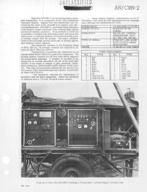
Clo<strong>se</strong> up of <strong>Radio</strong> Set AN/CRN-2 showing 1.Transmitter 2.Power Supply 3.Power Unit<br />
AN/ CRN-2