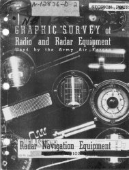
Radio Navigation Equipment - Signalspaning.se
Radio Navigation Equipment - Signalspaning.se
Radio Navigation Equipment - Signalspaning.se

Create successful ePaper yourself
Turn your PDF publications into a flip-book with our unique Google optimized e-Paper software.
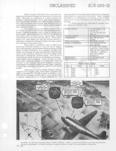
<strong>Radio</strong> Compass SCR-269-G was primarily designed<br />
to be u<strong>se</strong>d as a navigational instrument in army aircraft.<br />
Basically, the equipment is a radio receiver employing<br />
a superheterodyne circuit and certain additional<br />
es<strong>se</strong>ntial circuits necessary for radio compass operation.<br />
Two remote controls are provided, and, although only one<br />
control functions at a time, control may be readily switched<br />
from one to the other.<br />
The equipment has a frequency range of 200 kc<br />
to 1750 kc, covered in three bands, and calibrated in kilocycles.<br />
Only the frequency band in u<strong>se</strong> is visible on the<br />
tuning scale. <strong>Radio</strong> Compass SOR-269-G is manually tuned<br />
from either of two remote positions, with the bands switched<br />
electrically from the position having control. When installations<br />
are made which u<strong>se</strong> only one remote control, no<br />
switching of control is necessary andthe one radio control<br />
box u<strong>se</strong>d has control at all times.<br />
When u<strong>se</strong>d in conjunction with a suitable non-<br />
directional (vertical) antenna, a 14 or 28 volt do supply,<br />
one or two head<strong>se</strong>ts, and necessary interconnecting wiring,<br />
<strong>Radio</strong> Compass SCR-269-G is a complete operable unit<br />
capable of providing the pilot with automatic bearing indication<br />
of the direction, relative to the line of flight, of the<br />
transmitter creating the received signal. Also, by u<strong>se</strong> of<br />
a loop antenna, aural-null directional indications of a transmitted<br />
signal may be obtained. Aural reception of modulated<br />
radio frequency signals is possible with either the<br />
vertical or loop antenna, and aural reception of unmodulated<br />
signals is possible in each of the four ca<strong>se</strong>s. Selection<br />
of either type of reception is made by u<strong>se</strong> of a C.W-VOICE<br />
switch.<br />
There were- no Army Supply Program requirements<br />
as of 31 January 1945, since <strong>Radio</strong> Compass AN/<br />
ARN-7, covering the 100-200 kc band in addition to the<br />
200-1750 kc coverage of SCR-269-G, more nearly meets<br />
a military requirement for a compass adaptable for long<br />
May 1945<br />
UNCLAD SIFIED SCR-269-G<br />
range operation in connectionwith established low frequency<br />
transmitters in many parts of the world. <strong>Radio</strong> Compass<br />
AN/ARN-6, in development, is intended as the eventual<br />
replacement of both SCR-269-G and AN/ARN-7 in army<br />
aircraft.<br />
Test equipment for SCR-269-G includes Test<br />
Set -56-A and Test Set I-100.<br />
POWER INPUT 0.5 AMPERES @ 28<br />
VOLTS DC<br />
115-140 VOLTS, 400<br />
CPS;_AC<br />
POWER OUTPUT 600 MILLIWATTS PEAK<br />
FREQUENCY 200-1750 KC IN 3<br />
BANDS<br />
TYPE OF SIGNAL CW; MCW; VOICE<br />
SIGNAL STRENGTH 40-50 MICROVOLTS<br />
PER METER<br />
ANTENNA 8" LOOP AND FIXED<br />
VERTICAL MAST WITH<br />
ONE OR TWO REMOTE<br />
CONTROL POSITION<br />
AND AUTOMATIC<br />
ROTATION<br />
SENSITIVITY 3.5 MICROVOLTS<br />
SELE CTIVITY 4.5-13 KO<br />
TUBE- COMPLEMENT<br />
NO. TYPE NO. TYPE<br />
2 6F6 1 6J5<br />
1 5Z4 1 6N7<br />
4 6K7 1 6SC7<br />
1 6L7 2 2051<br />
2 6B8<br />
In additic 1 to its high frequency band of 2800 to 5900 kc.. <strong>Radio</strong> Compass SCR-269-G provides facilities for<br />
homing and plotting of aircraft positions similar to tho<strong>se</strong> of other Automatic <strong>Radio</strong> Compas<strong>se</strong>s.