Radio Navigation Equipment - Signalspaning.se
Radio Navigation Equipment - Signalspaning.se
Radio Navigation Equipment - Signalspaning.se

You also want an ePaper? Increase the reach of your titles
YUMPU automatically turns print PDFs into web optimized ePapers that Google loves.
Marker Beacon Transmitting <strong>Equipment</strong> RC-115,<br />
when u<strong>se</strong>d with Marker Beacon Receiving <strong>Equipment</strong>s RC-<br />
39, RC-43, RC-193, AN/ARN-12 or AN/ARN-8 constitutes<br />
complete marker beacon transmitting facility for any one<br />
ground position inconnection with the AAFInstrument Approach<br />
System. This equipment generates and radiates vertically<br />
a keyed, or -continuous, modulated signal in a fan<br />
shaped pattern. The signal thus transmitted is effective<br />
only when the receiving antenna is directly above and approximately<br />
parallel to that of the transmitter. It is, therefore,<br />
possible for the pilot to obtain visual and aural indication<br />
of his approximate horizontalo position along his line<br />
of flight with respect to the landing field.<br />
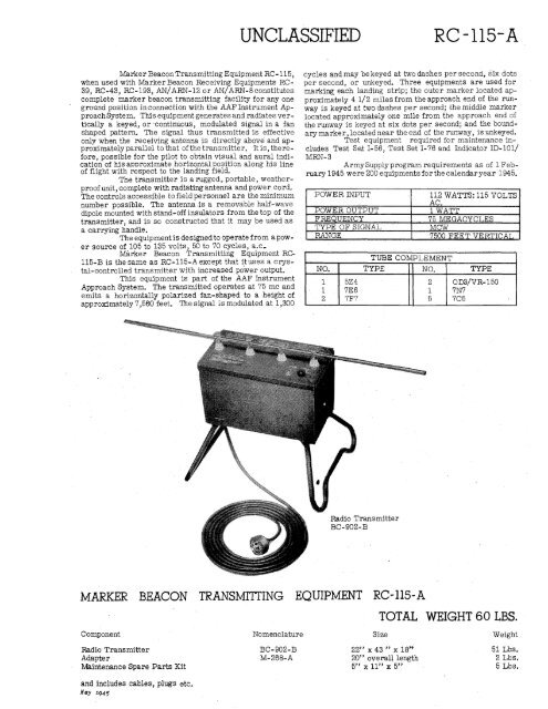
The transmitter is a rugged,.portable, weatherproof<br />
unit, complete with radiating antenna and power cord.<br />
The controls accessible to field personnel are the minimum<br />
number possible. The antenna ,is a removable half-wave<br />
dipole mounted with stand-off insulators from the top of the<br />
transmitter, and is so constructed that it may be u<strong>se</strong>d as<br />
a carrying handle.<br />
The equipment is designed to operate from a power<br />
source of 105 to 135 volts, 50 to 70 cycles, a.c.<br />
Marker Beacon Transmitting <strong>Equipment</strong> RC-<br />
115-B is the same as RC-115-A except that itu<strong>se</strong>s a crystal-controlled<br />
transmitter with increa<strong>se</strong>d power output.<br />
This equipment is part of the AAF Instrument<br />
Approach System. The transmitted operates at 75 me and<br />
emits a horizontally polarized fan-shaped to a height of<br />
approximately 7,560 feet. The signal is modulated at 1,300<br />
MARKER BEACON<br />
Component<br />
<strong>Radio</strong> Transmitter<br />
Adapter<br />
Maintenance Spare Parts Kit<br />
and includes cables, plugs etc.<br />
Nay 1945<br />
UNCLA SSIFIED RC-115-A<br />
cycles and may be keyed at two dashes per <strong>se</strong>cond, six dots<br />
per <strong>se</strong>cond, or unkeyed. Three equipments are u<strong>se</strong>d for<br />
marking each landing strip; the outer marker located approximately<br />
4 1/2 miles from the approach end of the runway<br />
is keyed at two dashes per <strong>se</strong>cond; the middle marker<br />
located approximately one mile from the approach end of<br />
the runway is keyed at six dots per <strong>se</strong>cond; and the boundary<br />
marker, located near the end of the runway, is unkeyed.<br />
Test equipment required for maintenance includes<br />
Test Set 1-56, Test Set I-76 and Indicator ID-101/<br />
MRN-3<br />
Army Supply program requirements as of 1 February<br />
1945 were 200 equipments for the calendar year 1945.<br />
POWER INPUT 112 WATTS: 115 VOLTS<br />
AC.<br />
POWER OUTPUT 1 WATT<br />
FREQUENCY 75 MEGACYCLES<br />
TYPE OF SIGNAL MCW<br />
RANGE 7500 FEET VERTICAL<br />
TUBE COMPLEMENT<br />
NO. TYPE NO. TYPE<br />
1 5Z4 2 OD3/VR-150<br />
1 7E6 1 7N7<br />
2 7F7 5 705<br />
<strong>Radio</strong> Transmitter<br />
BC-902-B<br />
TRANSMITTING EQUIPMENT RC-115- A<br />
Nomenclature<br />
BC-902-B<br />
M-268-A<br />
TOTAL WEIGHT 60 LBS.<br />
Size Weight<br />
22" x 43 " x 18"<br />
20" overall length<br />
5" x 11" x 5"<br />
51 Lbs.<br />
2 Lbs.<br />
5 Lbs.