WSCAD 5.2 - FTP Directory Listing
WSCAD 5.2 - FTP Directory Listing
WSCAD 5.2 - FTP Directory Listing

Create successful ePaper yourself
Turn your PDF publications into a flip-book with our unique Google optimized e-Paper software.
<strong>WSCAD</strong> <strong>5.2</strong><br />
Getting Started<br />
© Copyright 1990-2007 <strong>WSCAD</strong> electronic GmbH All Rights reserved
Copyright © 1990-2007 by <strong>WSCAD</strong> electronic GmbH<br />
Kreisstraße 28<br />
D-85232 Bergkirchen<br />
Office Phone: +49-8131-3627 -0<br />
Office Fax: -52<br />
Sales Phone: -98<br />
Hotline Phone: -99<br />
Internet: http://www.wscad.com<br />
Email: Info@wscad.com<br />
All rights reserved. No part of this publication may be reproduced, stored in a<br />
retrieval system, or transmitted, in any form or by any means, electronic,<br />
mechanical photocopying, recording, or otherwise, without prior permission of the<br />
publisher.<br />
<strong>WSCAD</strong> electronic GmbH makes no warranty of any kind with regard to this<br />
material, including, but not limited to, the implied warranties of merchantability and<br />
fitness for particular purpose. <strong>WSCAD</strong> electronic GmbH shall not be liable for errors<br />
contained herein nor for incidental consequential damages in connection with the<br />
furnishing, performance, or use of this material.<br />
The information contained in this document is subject to change without notice.<br />
<strong>WSCAD</strong> ® is a registered trademark of <strong>WSCAD</strong> electronic GmbH. Other brands and<br />
their products are trademarks or registered trademarks of their respective holders<br />
and should be noted as such.
Table Of Contents<br />
Introduction........................................................................................... 3<br />
General ............................................................................................ 3<br />
Documentation.................................................................................. 4<br />
Features................................................................................................ 7<br />
General Information about <strong>WSCAD</strong> 5.................................................... 7<br />
Hardware requirements .................................................................... 10<br />
Working with <strong>WSCAD</strong> 5 ......................................................................... 11<br />
Restrictions of the Demo version ....................................................... 11<br />
Starting <strong>WSCAD</strong> 5 ................................................................................ 13<br />
Screen layout.................................................................................. 13<br />
Mouse operation .............................................................................. 16<br />
Function keys....................................................................................... 17<br />
General .......................................................................................... 18<br />
Configuring the screen layout............................................................ 19<br />
Design capture..................................................................................... 21<br />
General .......................................................................................... 21<br />
Norm IEC 61346.............................................................................. 21<br />
Setting up a project ......................................................................... 21<br />
Creating new pages for a drawing set................................................. 25<br />
Adjusting the practice files................................................................ 28<br />
Page configuration ........................................................................... 29<br />
Placing Components.............................................................................. 31<br />
General .......................................................................................... 31<br />
Load a symbol without parts ............................................................. 31<br />
Placing symbols with database .......................................................... 35<br />
Symbols with texts supplement ......................................................... 39<br />
Editing Terminals.................................................................................. 40<br />
General .......................................................................................... 40<br />
Placing Terminals............................................................................. 40<br />
Terminal browser............................................................................. 43<br />
Input via Terminal Number ............................................................... 45<br />
Drawing macros ................................................................................... 46<br />
Inserting drawing macro................................................................... 46<br />
Contactor Manager ............................................................................... 48<br />
General .......................................................................................... 48<br />
Semi-automatic Contactor Manager ................................................... 48<br />
Contactor Manager........................................................................... 58<br />
Full automatic Contactor Manager...................................................... 63<br />
Cross-reference Navigator ................................................................ 64<br />
PLC Manager........................................................................................ 66<br />
General .......................................................................................... 66<br />
First you load the PLC main module ................................................... 66<br />
Loading the individual PLC channels first............................................. 68<br />
Modifying the PLC byte address ......................................................... 71<br />
Inserting connections (destination wiring) ............................................... 73<br />
General .......................................................................................... 73<br />
Shortcuts........................................................................................ 74<br />
Inserting corners ............................................................................. 75<br />
Inserting direction symbols (T-pieces)................................................ 75<br />
Open line ends ................................................................................ 76<br />
Completing the drawing sheets.......................................................... 76<br />
Naming lines........................................................................................ 77<br />
General .......................................................................................... 77<br />
Inserting potential arrows................................................................. 77<br />
Completing the schematic...................................................................... 80<br />
1
Getting Started<br />
2<br />
General .......................................................................................... 80<br />
Page 3............................................................................................ 80<br />
Page 2............................................................................................ 80<br />
Cable Manager ..................................................................................... 82<br />
General .......................................................................................... 82<br />
Drawing cables with the Cable Manager.............................................. 82<br />
Splitting cables................................................................................ 84<br />
Cable shield .................................................................................... 85<br />
Cable Browser ................................................................................. 86<br />
Modify Object properties................................................................... 86<br />
Automatic functions .............................................................................. 89<br />
General .......................................................................................... 89<br />
Auto-numbering .............................................................................. 89<br />
Auto cross reference ........................................................................ 90<br />
Material browser.............................................................................. 91<br />
Control Cabinet Layout.......................................................................... 93<br />
General .......................................................................................... 93<br />
Inserting components....................................................................... 94<br />
Excluding unwanted components ....................................................... 96<br />
Construction lines................................................................................. 97<br />
Inserting the control cabinet ............................................................. 97<br />
Inserting the mounting plate............................................................. 98<br />
Drawing Cable trays, top hat rails and collection bars........................... 99<br />
Inserting assembly symbols .............................................................. 99<br />
Inserting terminals..........................................................................101<br />
Putting symbols on control cabinet door ............................................102<br />
Calculate dimensions of the Control cabinet .......................................102<br />
Drawing sheet variables ..................................................................103<br />
Foreign Languages..........................................................................105<br />
Automated listings...............................................................................109<br />
General .........................................................................................109<br />
Individual listings via the 'Automatic funct.' menu...............................109<br />
Individual listings via the Project manager .........................................109<br />
Automated listings of an entire Project ...................................................110<br />
General .........................................................................................110<br />
Specific information for the Project summary .....................................110<br />
Starting the creation of automated listings.........................................112<br />
Project data ...................................................................................113<br />
Revision history..............................................................................113<br />
Schematics ....................................................................................113<br />
Control cabinet layout .....................................................................113<br />
Terminal chart................................................................................114<br />
Cable list .......................................................................................114<br />
Cable chart ....................................................................................115<br />
Wiring chart ...................................................................................115<br />
Material list....................................................................................116<br />
Reference name chart .....................................................................116<br />
Summary.......................................................................................117<br />
Creating the project database ..........................................................117<br />
Output to printer ............................................................................117<br />
Creating a symbol ...............................................................................121<br />
Creating a symbol...........................................................................121<br />
<strong>WSCAD</strong> Services..................................................................................125<br />
In conclusion .................................................................................125<br />
Service Software - Subscription........................................................125<br />
Service Digitizing Drawings..............................................................126<br />
Epilogue .............................................................................................127<br />
Printout of important drawings..............................................................128
Introduction<br />
General<br />
Introduction<br />
With <strong>WSCAD</strong> 5 you have chosen one of the most advanced programs to create<br />
electrical schematic drawings, with an excellent price/performance ratio.<br />
<strong>WSCAD</strong> 5 is already being used successfully by more than 25.000 users worldwide.<br />
Careful consideration has been given to user-friendliness and simplicity<br />
The easy-to-use On-line Help of <strong>WSCAD</strong> 5 gives instant on-screen<br />
answers to your questions.<br />
<strong>WSCAD</strong> 5 is undoubtedly one of the most effective CAD programs you can<br />
buy. You have instant access to all the functions and you can browse through your<br />
drawings easily, but most important, the program’s simplicity of operation and<br />
rapid processing enable you to produce extensive projects in a very short<br />
time. Whatever you are doing, <strong>WSCAD</strong> 5 shows you the simplest way to<br />
accomplish your task. Clear menus, and the additional online information of the two<br />
mouse buttons functions makes <strong>WSCAD</strong> 5 a very easy program to use.<br />
The challenge of combining versatility of functions with great simplicity of use has<br />
been fully met in <strong>WSCAD</strong> 5. It provides you with all common functions of a CAD<br />
software program for generating electrical schematics (and some unusual ones as<br />
well), for example: loading symbols from libraries, combining them, creating new<br />
symbols, … .<br />
In addition, <strong>WSCAD</strong> 5 offers you much more! With functions such as subsequent<br />
rotation, mirroring, copying, moving, automatic assignment of reference numbers,<br />
automatic cross-references, free-form design of drawing frames, universal list<br />
generation, fully automatic contactor management, PLC manager and versatile<br />
configuration options you have all the features of a powerful circuit diagram<br />
generation program. And this list is by no far complete.<br />
On top of this we are constantly working to develop the program. Apart from the<br />
creativity of our programmers, feedback from users is an essential part of<br />
development. Please do not hesitate to give us your comments and suggestions at<br />
any time!<br />
Some comments about software protection: Due to previous experience, we are<br />
forced to deliver our software with a dongle. This may be a new situation for you,<br />
but this protection provides security for the program and enables us to maintain a<br />
low price, by providing a high degree of performance and functionality at the same<br />
time.<br />
For security reasons, it is possible to make as many copies of the original files as<br />
you like and install them on several other PCs. However, you can only use the<br />
program if the dongle is connected to one of the PC’s parallel or USB ports.<br />
3
Getting Started<br />
Documentation<br />
General<br />
By offering a software-service contract we ensure essential further development of<br />
<strong>WSCAD</strong> to remain compliant with new legal regulation. The software service<br />
ensures timely automatic updates are immediately at your disposal. As well as<br />
being updated automatically with each new major release of our software products,<br />
you will receive continuous minor documentation changes and function<br />
improvements that we make from time to time.<br />
As the documentation and the software is integral though on line help, we have decided to<br />
provide “First steps …” as the only printed documentation.<br />
Up-to-date documentation can be found as 'WebHelp' on our web-site. You can<br />
activate the help function directly within the <strong>WSCAD</strong> software with .<br />
Online Help – WebHelp<br />
With the menu command 'Help –WebHelp' or , you can start directly start<br />
online help. Online help is installed automatically on your system and you can<br />
use it continuously. If your PC has web access and the connection (menu entry<br />
'Help-WebHelp') is activated, you can get direct assistance from the internet with<br />
function key .<br />
If you need a special information on a subject, press the key and the related<br />
help files will be loaded from the internet.<br />
4
Introduction<br />
The 'WebHelp' is always up to date. These files are complemented with tips and<br />
advice. You can have a look at these files on your system anytime.<br />
5
Features<br />
General Information about <strong>WSCAD</strong> 5<br />
<strong>WSCAD</strong> is modular structured, there fore you are able to start with the Basic -<br />
version and, at a later time, expand it to a higher-version (Compact or<br />
Professional) with more features. Drawings that have been made with a lower<br />
version are fully compatible with higher versions.<br />
The three software modules of <strong>WSCAD</strong> 5 which are build up on each other<br />
containing a tried and tested range of functions.<br />
The Basic version is particularly suitable for commissioning, when the planning<br />
itself was already completed and no more major alterations are anticipated. It is<br />
equally well suited to the creation of smaller and less extensive projects.<br />
The Compact version is often found in the maintenance department. The strength<br />
of the Compact version is in the adaptable circuit design, such as when an<br />
installation or machine already exists and needs modifications. In addition, this<br />
version is especially suitable for the creation of diagrams for small to medium-sized<br />
projects. Various automatic functions are available, such as cross-referencing,<br />
terminal charts, numbering and contact mirroring.<br />
The Professional version is used in the planning, development and<br />
documentation of new projects. Here the user has at his disposal an extensive<br />
range of powerful online and monitoring functions which are indispensable in the<br />
creation of new projects. Errors are eliminated from the beginning and productivity<br />
is increased.<br />
It does not matter with which version you will start with. There are no restrictions<br />
on upgrading from a lower module to a higher one. Single-user licences or network<br />
licences with common access to project data, database and libraries, or<br />
combinations of these, offer a systems-oriented method of working.<br />
- Schematic<br />
General Basic Compact Professional<br />
Drawing pages 10000 10000 >10000<br />
Sub pages <br />
New design <br />
Project management with file preview and sorting functions <br />
Project manager with individual listings. Project-specific information is<br />
automatically copied into the drawing frame <br />
Hide and show of several projects <br />
Export of several projects <br />
Sorting in 2 levels <br />
Project import/export <br />
Unit/Field designation; Unit/Field region - - <br />
Text Box <br />
Path text <br />
Black Box - <br />
Destination wiring <br />
Material browser - - <br />
7
Getting Started<br />
Text find/replace - <br />
Free configuration of drawing frames and lists (layout) <br />
Foreign language display/translation / - / - / <br />
Dimensions <br />
Printout labels of equipment, cables and terminals - <br />
8<br />
Drawing functions Basic Compact Professional<br />
- Schematic<br />
Choice of standards: Facility to work with old standard JEC 40719 or new<br />
JEC 61346 standard <br />
Symbol explorer with preview when loading a symbol, including symbol<br />
search and favourites <br />
Symbol editor for drawing own schematic symbols <br />
Text box: used for more than 100 characters with import functionality <br />
Direct access to function text and additional texts <br />
Zooming with mouse wheel and keyboard +/- <br />
Sequential and unique number for project pages - - <br />
Drawing macro Explorer with preview <br />
Terminal browser functions - <br />
Drawing plug + socket together / plug + socket separately / - / / <br />
- Floor plan<br />
Symbol libraries of all areas for electrical installation <br />
Symbol editor for drawing own electrical installation <br />
Drawing functions for floor plans <br />
Drawing format DIN and free format until 30mx30m <br />
Scale 1:1 until 1:1000 <br />
Fly Eye for display actually position in the drawing <br />
Clearly arranged floor management with installation zones <br />
Print preview of the drawings <br />
Snap functions <br />
- Schematic<br />
Automatic functions Basic Compact Professional<br />
Numbering of symbols - <br />
Generating cross references with designation wiring/online - / - / <br />
Automatic generation of line names in various forms - - <br />
Control cabinet manually / semi automatic / - / - / <br />
Terminal browser for locating and modifying terminals, single terminal,<br />
multi level terminal, jumper - <br />
Cable manager & connector manager - - <br />
Contactor management - <br />
Contactor manager - - <br />
Coil cross reference / generate reflector - <br />
Coil cross reference & contact manager online - - <br />
Generate PLC cross references - <br />
PLC cross references and PLC manager online - - <br />
Replacing drawing frames -
- Schematic<br />
Features<br />
Automated listings/charts Basic Compact Professional<br />
Separate listings (terminal chart, material list, … ) - <br />
Automated listing for all lists - - <br />
Project data - <br />
Summary - <br />
Revision history - - <br />
Terminal Chart - <br />
Connector chart - - <br />
Cable list - - <br />
Cable chart - - <br />
Wiring chart - - <br />
Reference list - - <br />
Material list - <br />
- Schematic<br />
Interfaces Basic Compact Professional<br />
DWG/DXF/HPGL Export <br />
DWG/DXF/HPGL Import <br />
VNS Export - - <br />
ASCII, ACCESS, Excel, dBase, Import/Export (Data) - - <br />
Import of parts data via ECAD standard component interface - - <br />
UGL/UGS Export - - <br />
Import of ASCII-, Excel- und Datanorm 4.0 - files - - <br />
Material list output as ACCESS, dBase, ASCII or Excel - - <br />
Label-Export to Grafoplast, Phoenix, Murrplastik, Excel or ACCESS - <br />
Import/Export of SEQ list for PLC module as Excel, SEQ-txt-format - - <br />
Output to ASCII: Material list - <br />
Export to BMP-, PCX- and PNG- format <br />
- Floor plan<br />
DWG/DXF Import with taking over all layers <br />
New features of <strong>WSCAD</strong> <strong>5.2</strong><br />
Basic Compact Professional<br />
- project management:<br />
Docking mode: open simultaneously the project manager and the drawing<br />
files<br />
<br />
File description is shown in the project manager window <br />
- interfaces:<br />
DWG/DXF-Import with selection of layers and position preview <br />
Terminal: Output to WAGO ProServe Smart DESIGNER 4.1 - - <br />
Labels: copy function for multiple output - <br />
Cable list / cable plan: Output to Excel/Access - - <br />
- drawing function:<br />
Online symbol access via internet (only with software subscription contract) <br />
Online article data via internet (only with software subscription contract) - - <br />
ProjectWizard (Add-On): test version with 5 pages - - <br />
Browser for managing line names - - <br />
PLC: virtual placing of main elements - - <br />
Info-Link for placed symbols (e.g. name plates) with access to the symbol<br />
parameters / part database<br />
- / - / <br />
9
Getting Started<br />
Creation helping lines with short-cuts within symbol editor / schematics /<br />
control cabinet<br />
<br />
Input the code of plugs via dialog - - <br />
Expanded search and replace function - <br />
Copy properties (lines, simple text etc.) <br />
- cable management:<br />
Cable browser - <br />
Input of length cable - - <br />
Input the code of colors via dialog - - <br />
- contactor management:<br />
Change contact of occupied contactor - - <br />
- symbol editor:<br />
Command toolbars for all menu commands <br />
modify symbols via dialog (pin table) <br />
create symbol with access to the part database - - <br />
Dialog with prepared symbol allocators <br />
Import DWG/DXF-files and fit to the grid <br />
- translation / lexicon:<br />
Optimized translation functions - - <br />
Translation word by word - - <br />
- floor plan:<br />
DWG/DXF-Import with selection of layers <br />
Undo after drawing of lines <br />
comfortable positioning of symbols altitude in the installation zone <br />
Cable/lines: predefined via expand to 20 pc. <br />
Type of lines: drawing of spline lines (curved lines) <br />
Hardware requirements<br />
Hardware requirements Minimum requirements Recommend<br />
Operation System: Windows 2000/XP Windows XP<br />
CPU: 1,6 GHz 3 GHz<br />
RAM: 256 MB 512 MB<br />
Harddisk: 500 MB 1 GB<br />
Graphics Card: 64 MB 256 MB<br />
Internet access: - <br />
Monitor: standard wide screen<br />
Make sure that the newest Microsoft service packages are installed!<br />
10
Working with <strong>WSCAD</strong> 5<br />
Restrictions of the Demo version<br />
The Demo version of <strong>WSCAD</strong> 5 has all features of the Professional version (if<br />
you select this option), including all automatic functions such as contactor<br />
manager, database links, cross references, numbering and so on. Only the output<br />
functions (Printer, DXF/VNS-export) are restricted. Please select after inserting<br />
Demo CD the option "start <strong>WSCAD</strong> <strong>5.2</strong> demo setup" .<br />
After a view steps you're able to choose the feature you will work with.<br />
11
Getting Started<br />
With the Demo version only a few libraries are installed, containing the<br />
components required for the practice example plus some general components. The<br />
full licence version contains very comprehensive libraries with over 1000<br />
symbols, and the Professional version includes more than 250 varied contact<br />
combs, as well as several hundred mechanical components for the control cabinet<br />
layout.<br />
Similarly the database contains only those entries which are needed for the practice<br />
example. The Professional version contains a very comprehensive database with<br />
thousands of parts from various manufacturers.<br />
Warning<br />
Drawings which are created or modified with the Demo version cannot be<br />
edited with a full licence version. So take care!<br />
This demonstration manual is only a brief description of the program and contains a<br />
short example, some information about the installation and some general hints for<br />
using the program. You have full access to the on-line help files of <strong>WSCAD</strong> 5.<br />
12
Starting <strong>WSCAD</strong> 5<br />
Working with <strong>WSCAD</strong> 5<br />
After installation has been successful completed you will find the program group<br />
'<strong>WSCAD</strong> 5. on your screen. You will see icons for the program, on-line help, the<br />
Read me file and the Uninstall program. You will also find icons for the <strong>WSCAD</strong><br />
file viewer WSVIEW and the associated help file.<br />
<strong>WSCAD</strong><br />
<strong>5.2</strong><br />
Demo<br />
To start <strong>WSCAD</strong> double click on the icon created on the desktop during<br />
installation.<br />
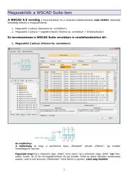
Screen layout<br />
After starting <strong>WSCAD</strong> 5, the screen typically looks as shown below:<br />
The pull down menus<br />
With the pull down menus you can select appropriate commands, or you have<br />
access to some of the most frequently used commands by clicking on an icon<br />
button. To see what the icons mean, just position the mouse pointer on each one in<br />
turn to reveal the ‘tool tip’ fly-out.<br />
13
Getting Started<br />
The mouse pointer/cursor arrow<br />
Grid<br />
The arrow or cursor location determines the actual position within the drawing. You<br />
can position the arrow or cursor with the mouse. In addition you can position with<br />
the cursor keys or by type in the specific co-ordinates. It is also possible to change<br />
the format of the cursor (e.g. to a crosshair) by using 'Settings - Options'.<br />
As a drawing aid, a grid can be displayed if required by turning it on or off with the<br />
function key . The grid spacing can be set ('Settings - Options'), the default<br />
spacing is 2.5 mm. Components are created to match the grid and automatic<br />
connection requires components to be in line with each other, it is helpful to keep<br />
the grid displayed and switch the Snap Mode 'on' with the function key .<br />
Mouse button functions<br />
The functions of the left and right mouse buttons are always displayed by the little<br />
yellow mouse at the bottom of the screen. This makes <strong>WSCAD</strong> much more easier<br />
to use. It is helpful to have a look at them frequently! The left button<br />
(corresponding to the key) is used typically to execute a command. The<br />
right button (corresponding to the key) is typically used to exit a<br />
command or to activate the property menu.<br />
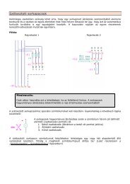
Free memory<br />
The capacity of free memory is shown as a percentage, on the right bottom edge of<br />
the <strong>WSCAD</strong> window. If available memory is getting low, the 'Compress' command<br />
in File menu should help to increase the memory capacity.<br />
Drawing co-ordinate (Path)<br />
To locate components in a drawing easily, the drawing is divided into numbered<br />
vertical strips, numbered horizontally, and this number is known as the vertical<br />
path. The width of each strip and the numbering sequence are set in 'Settings -<br />
Common Settings - Cross reference'. It is this path number that is used, along<br />
with the sheet number, to indicate the location of a cross referenced element.<br />
14
File names<br />
Enter for example an 'A' as first vertical sign.<br />
Working with <strong>WSCAD</strong> 5<br />
In the centre at the bottom of the screen, next to the current sheet size, is a<br />
number and letter that indicates the grid reference of the drawing that the cursor is<br />
currently located in.<br />
The top bar of the Windows screen displays the name of the current project and of<br />
the active drawing. If you are working in the symbol editor or selecting a<br />
component from the library, you will see the name of the active library in this field,<br />
instead of the drawing file name.<br />
Common input field<br />
When inserting text or co-ordinates with the keyboard, you will see these values<br />
appear in a box at the bottom of the screen.<br />
Status and prompt display<br />
At the lower left hand side of the screen, there is a box that displays the status of<br />
settings and commands. The letters (S, O, A) are displayed when the corresponding<br />
function is activated.<br />
15
Getting Started<br />
16<br />
The status display contains:<br />
Snap function on/off 'S' as 1st character<br />
Ortho Mode on/off 'O' as 2nd character<br />
Auto.-connecting on/off 'A' as 3rd character<br />
Mouse operation<br />
When working with a graphical user interface such as Windows it is normal to work<br />
with the mouse to move the cursor. However the cursor can also be used for other<br />
tasks as e.g. inserting components.<br />
One click with the left mouse button indicates a positive confirmation. The<br />
internal functions of <strong>WSCAD</strong> 5 allow the right button to be used for cancelling, as<br />
in the earlier version, but not in case of the main menu, because this is not<br />
compatible with standard Windows functions.<br />
Moving and sizing of individual windows are normal parts of the Windows operation<br />
and the form of the cursor gives visual hints on how to do.<br />
The right mouse button gives you also access to a very important function of the<br />
program. When you position the cursor on any object, and click the right mouse<br />
button, you will see a specific menu displaying the characteristics of the selected<br />
object. This applies not only to elements within the drawings but also to the buttons<br />
on the toolbars.<br />
You can use the mouse to mark an area (rectangle) of the drawing to (for example)<br />
move or copy the selected components.<br />
If you want to select a particular area of a drawing window to edit or to copy it,<br />
you can do by using the mouse. Click with the left mouse button on a corner of the<br />
desired area, hold the mouse button down and move the cursor with the<br />
mouse. This will cause a rectangle to be drawn and when the mouse button is<br />
released all components within the rectangle will be shown highlighted. Then you<br />
can apply the copy command to this area. To cancel the selection you simply click<br />
anywhere in the drawing window.<br />
Another useful feature is 'Panning', which moves the whole picture in the drawing<br />
window when the cursor bumps against the side of the window. However this<br />
function is only activated by holding the key down, or when you are<br />
loading a symbol or drawing a line. This prevents the screen from ‘panning’ every<br />
time you move the mouse towards the menus or toolbars.<br />
The Object properties concept provides a new and very fundamental feature. A<br />
click with the right mouse button opens a menu, which relates exactly to the object<br />
on which the cursor is located. For example, if the object is a component, you will<br />
get the component parameters menu and its applicable commands, if you click near<br />
a command toolbar you can switch them on and off. By using this feature<br />
frequently you will soon come to appreciate it’s usefulness!<br />
Mouse wheel zoom<br />
On the basis of the current cursor position the representation is constantly<br />
increased and/or reduced depending upon direction of rotation, which picture<br />
shifted after possibility in such a way that the cursor position becomes the picture
Working with <strong>WSCAD</strong> 5<br />
centre. The function is activated and/or deactivated through to press on the mouse<br />
wheel. An identical effect as over mouse wheel tricks you obtain with + and - keys<br />
Function keys<br />
Even with a graphical interface the function keys should not be forgotten, as they<br />
can also be used to give fast access to frequently used commands. For instance you<br />
will often find the key very useful for fitting your drawing to the current<br />
window, and for rapid Zooming, for Snap mode switching or<br />
for Grid display switching.<br />
Every experienced Windows user, will of course, already be familiar with function<br />
key: for On-line help or WebHelp which will give access to the whole of the<br />
reference manual and there are also “topical” hints and tips.<br />
The full list of the available function keys is shown below:<br />
Key Function<br />
On-line help<br />
Zoom in at the cursor (enlarge picture)<br />
Zoom out (reduce picture)<br />
<br />
Zoom Extents (fill the window<br />
completely)<br />
- Scale the display 1:1<br />
- Quit <strong>WSCAD</strong><br />
Toggle Snap mode on/off<br />
Toggle Orthogonal mode on/off<br />
Toggle Grid display on/off<br />
Display co-ordinates in mm/inches<br />
Cursor zero point absolute/relative<br />
Auto-connection on/off<br />
Redraw current window<br />
Full screen mode on/off<br />
Hint<br />
Don’t forget when you install the demo version you also get the complete<br />
Online Help of the licence version. This means that you can access virtually<br />
the whole of the reference manual.<br />
17
Getting Started<br />
General<br />
In addition to normal text input and the function keys, you can also access all the<br />
menu commands from the keyboard: simply press the key and the<br />
underlined letters from the menu. You also use the key to quit operations<br />
even in Windows.<br />
Important keyboard functions<br />
There are also some further keyboard functions that are very important:<br />
• The four cursor keys are equivalent to the mouse functions during drawing<br />
operations. Sometimes it is more easy to use these keys instead of the mouse for<br />
positioning. Holding down the key speeds up the cursor movement.<br />
• In most cases, the key has the same function as the left mouse button.<br />
• With or you can move through the individual sheets<br />
in a set of drawings.<br />
• With you can copy the components of a selected area (see “Mouse<br />
operation”), i.e. these components are transferred to a temporary file and onto<br />
the Windows clipboard.<br />
• With or you can re-insert this temporary file. This is the same<br />
as the command ‘insert block’.<br />
• With or you can delete the elements in the selected area.<br />
• With you can activate the UNDO function.<br />
Hint<br />
If you want to enter new text, and text is already entered in the text entry<br />
window, it is automatically selected and shown as an inverse highlight. If<br />
you wish to keep the pre-entered text and just modify it, you either<br />
position the cursor at the appropriate point and press the left mouse<br />
button, or press the key or the key. If you enter<br />
new text directly, the selected text is immediately erased. Previous entered<br />
text you can select by clicking the arrow down button located right of the<br />
text edit line.<br />
Special key combinations<br />
When drawing with destination wiring symbols (DW) the following Shortcuts are<br />
available:<br />
18<br />
Shortcut DW Elements<br />
-left arrow T left<br />
right arrow T right<br />
- up arrow T-top<br />
- down arrow T-bottom<br />
- left arrow Arrows<br />
- right arrow "<br />
- up arrow Angles<br />
- down arrow "
Configuring the screen layout<br />
Working with <strong>WSCAD</strong> 5<br />
The command toolbars and the library toolbars can be docked against the other<br />
side of the screen or placed as a free-standing window. You can try this<br />
easily: move the cursor onto a toolbar (but not onto a button), press the left mouse<br />
button and then move the cursor, keeping the mouse button pressed. The new<br />
position of the toolbar appears in outline and as soon as you release the mouse<br />
button the toolbar appears in this position.<br />
If you click once with the right mouse button on the area beside a docked toolbar or<br />
in the window header, you will get a small menu that gives you (e.g.) a list of all<br />
available library toolbars. With one mouse click you can activate or hide a library<br />
toolbar.<br />
Of course you can configure the toolbars: If you click with the right mouse button<br />
on a button, you can immediately insert a new button (or a separator) in this<br />
position. Click on the new button, select ‚Record’ and then use the relevant<br />
command from the menu bar. The command is accepted and its icon appears on<br />
the button.<br />
The buttons of the command toolbar have preset icons, but for icons on the symbol<br />
toolbars you have a completely free hand. The button is assigned via the<br />
Component Editor, because each button must be assigned to both a component<br />
name and a library. You can ‚snapshot’ the relevant icon out of the component<br />
editor and apply different background colours if you wish.<br />
Hint<br />
You can design the buttons on the library toolbars by yourself, using the<br />
symbol editor.<br />
The above description has been kept deliberately simple. If you would like to know<br />
more, please use the Online Help. Look in the section 'Working with <strong>WSCAD</strong> 5' to<br />
find further information on the individual elements of the screen layout. In the<br />
section 'Settings – Configure Screen' you will find a detailed description of<br />
creating and managing the toolbars.<br />
19
Design capture<br />
General<br />
In this chapter, you will learn about the most important features of the<br />
Professional version of <strong>WSCAD</strong> 5 by completing a small sample project. You will<br />
use the 'Favourites' 'EXAMPLE' and the database 'EXAMPLE.MDB' and you may<br />
find it helpful to study the sample drawings on the preceding pages. The complete<br />
practice example can be found as '<strong>WSCAD</strong> example project 1' in the Project<br />
Manager.<br />
Hint<br />
Please note that this sample schematic aims to answer questions of the<br />
type: "How can I ....?" It does not reflect the usual procedure for creating a project.<br />
While reading this section, please refer to the foregoing sample drawings<br />
Norm IEC 61346<br />
All examples are created referring the norm IEC 61346 which is valid since<br />
01.June.2003. This international norm changes the reference names of symbols to<br />
represent the symbols function oriented and administered.<br />
In <strong>WSCAD</strong> it is possible to draw with the “old norm” or with the “new norm”.<br />
The following example is using the “new norm”.<br />
Hint<br />
The new norm IEC 61346 contains function informed reference names. For<br />
this reason the existing reference names differ to the new reference<br />
names.<br />
e.g.: a manual motor starter have had a reference name “–Q”. Since<br />
01.June.2003 it is defined as a protection installation and now has the<br />
reference name “-F”.<br />
Setting up a project<br />
General<br />
The Project Manager is the central organizer for all your projects. It enables you<br />
for example to copy, to import and to export projects, and allows you to make<br />
auto-saves for creating regular backups. You can also set up a customer database<br />
referring back to this data later.<br />
The first step is to set up a new project. A folder is created which contains the<br />
entire files specific to the project. On the pull-down menu, select 'File – Project<br />
Manager'. This will open the Project Manager.<br />
Some example projects have already been created. To get the details of an existing<br />
project, select the project name with the mouse. In the right-hand window, all the<br />
information about that project is displayed. Now select from the menu 'Project-<br />
New', to create a new project. The following dialog appears:<br />
21
Getting Started<br />
Enter the project name as '<strong>WSCAD</strong> example'. The project name is automatically<br />
added to the preset project path. For the template, select 'A4-Horizontal..'. This<br />
template will be used for the entire project. It automatically inserts a specific frame<br />
into the drawing sheet when you are creating schematics or terminal charts.<br />
Hint<br />
Please make sure the option 'CPP – Mode' is switched off. Otherwise, you<br />
will be working in Combined Part Project mode, which is only necessary for<br />
very large projects.<br />
Exit with 'OK'.<br />
22
Design capture<br />
The project '<strong>WSCAD</strong> example' is opened automatically. You see the open project<br />
on the open book symbol! Now, in the right-hand window of the Project Manager,<br />
enter the information which has to appear on the drawing frame. Enter the<br />
following values (or something else):<br />
23
Getting Started<br />
Hint<br />
Double clicking the line 'Customer' takes you to the customer database.<br />
The project data is now complete. The next step is to create the drawing sheets.<br />
24
Creating new pages for a drawing set<br />
Design capture<br />
In order to draw a schematic diagram, start the Project Manager ('File – Project<br />
Manager') and open the directory tree for the project. Activate the project you will<br />
work with by clicking the right mouse button on 'Project name' and select 'Open'<br />
(not necessary, if the project is already open).<br />
Hint<br />
The main window of the Project Manager shows you which project is<br />
currently open.<br />
Now click with the right mouse button on 'Schematics' and select 'Create'.<br />
Hint<br />
You will also find the command 'Create' in the Project Manager menu under<br />
'Modify’. Nevertheless you must select 'Schematics' first.<br />
In this example you will be using '4' drawing sheets. Enter this number in the<br />
following dialog.<br />
25
Getting Started<br />
The next dialog already has 'File name' displayed. To open it, click the 'OK'<br />
button.<br />
If you need more sheets later on, you can add them to the existing sheets in the<br />
same way.<br />
26
Design capture<br />
Four Drawing sheets have been created and the data you entered in the Project<br />
Manager have been transferred automatically into the drawing sheets.<br />
Check the amount of pages by pressing the 'Next sheet' or 'previous page' keys<br />
to browse through the sheets.<br />
You see also the name of the drawing file and the sheet number at the top of the<br />
main window:<br />
The total number of sheets and the current page number are displayed<br />
automatically.<br />
Finally, go back to Sheet 1 of your example.<br />
27
Getting Started<br />
Adjusting the practice files<br />
If you are working with a licence version, you must now activate the example<br />
database. First, select 'Settings' on the menu, then the command 'Common<br />
Settings' and then the 'Database' tab.<br />
The display now lists the directories including information on the database.<br />
Click with the left mouse button in the database field and then click on the<br />
button.<br />
28
Design capture<br />
You will see this standard Windows dialog for selecting a file. Click on the file<br />
'example.mdb' and then 'OK'. You will automatically be returned to the<br />
'Database' tab in the 'Common Settings' dialog. You will see the name and the<br />
path of the selected file now correctly displayed. Store the setting by clicking the<br />
'OK' button. If you click 'Cancel' in the 'Common Settings' dialog, you will exit<br />
without storing any changes.<br />
Page configuration<br />
Before you begin to draw the example project, you should check some of the<br />
settings for your new project:<br />
Exit the Project Manager with 'OK' and click on 'Settings’ in the pull-down menu.<br />
Then select the command 'Options'. Check the following settings:<br />
29
Getting Started<br />
If you want to change the cursor form, then click on the relevant cursor symbol.<br />
Exit the 'Options' dialog with a mouse click on the 'OK' button.<br />
Hint<br />
Note the display in the information bar on the lower edge of the screen. It<br />
shows hints about the current command and the function of both mouse<br />
buttons.<br />
30
Placing Components<br />
General<br />
In <strong>WSCAD</strong> you have several options to load a symbol:<br />
• Load a symbol without parts<br />
• Load a symbol with parts<br />
Load a symbol without parts<br />
Details for all Versions Basic Compact & Professional version<br />
Design capture<br />
The first task is to place the main isolator switch, which is identified in the<br />
example drawing as '-Q1'. This is the so-called reference name which is<br />
incremented by automatic numbering. The component is placed without having<br />
access to the database, which is one of the functions of the Professional -<br />
version.<br />
Check whether the database access is deactivated or not. Select the menu<br />
command 'Settings– Common Settings', the tab 'Connect+Load' and disable<br />
the Option 'Take values from database'. Accept the message ('The cable<br />
manager must be ...') with 'OK' and leave the Common settings with 'OK'.<br />
31
Getting Started<br />
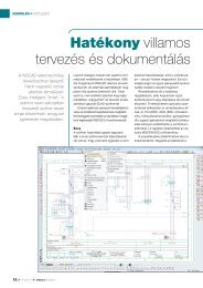
To load a component, select the 'Schematic' menu and then select 'Load symbol<br />
...'. The 'Symbol Explorer' will appear:<br />
32
Design capture<br />
The 'Symbol Explorer' offers several options to access the libraries or to load a<br />
symbol directly:<br />
• Loading a symbol directly from a library (Library)<br />
• Loading a symbol via the reference name (Designation)<br />
• Loading a symbol after a search (Search)<br />
• Loading a symbol as a favourite (Favourites)<br />
Hint<br />
In the Demo version the Symbol Explorer shows a reduced number of<br />
available libraries. The licence version contains many more libraries.<br />
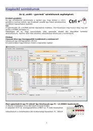
Go to the tab 'Favourites' and click on the '+' next to 'Example' if it is not yet<br />
open. All Component names are listed, choose 'Mainswitch_3pol' and you have a<br />
preview at the top of the symbol explorer.<br />
Select the component 'Mainswitch-3pol' using the left mouse button and 'OK' (or<br />
a double click).<br />
33
Getting Started<br />
Make sure that the Snap mode, (indicated by 'S', the first letter in the box on the<br />
information bar; switches it on/off) and Automatic connection ('A' is the<br />
third letter; function key switches it on/off) are turned on and displayed.<br />
34<br />
The component jumps from grid point to grid point with the snap<br />
mode on. This is necessary to ensure perfect alignment and valid<br />
connection of the components.<br />
Position the switch at the drawing (these are displayed on the status bar at the<br />
bottom right of your screen).<br />
Fix the component with the left mouse button or key. Now the symbol,<br />
explorer will be shown again and you can choose a further component. If you have<br />
finished placing components, you can press . If you have loaded the wrong<br />
component, you can delete it with 'Undo' in the menu 'Delete/Move' and load the<br />
correct one as described before.<br />
If you press the right mouse button before<br />
positioning the component, the 'Rotation' menu<br />
will appear. In addition to rotate, you can mirror the<br />
component, modify the component name and<br />
parameters, etc. or abort the command. The placed<br />
component has the reference name 'Q' and not<br />
'Q1' as shown in the completed example drawing.<br />
The number will be added later using the automatic<br />
numbering capability.<br />
Hint<br />
After placing the component the component a selection window will<br />
reappear. Simply exit by pressing .
Placing symbols with database<br />
Interesting for users of the Professional version<br />
Design capture<br />
The next task is to place additional components, but this time using the database,<br />
which is only possible with the Professional version.<br />
Hint<br />
In this example the database access does not apply to contactors and<br />
contacts.<br />
From the main menu choose 'Settings - Common Settings - Connect+Load<br />
Tab’ and tick 'Take values from database'. Also check that in the tab<br />
'Contactor and PLC Modules' the options 'Activate Contactor Manager' and<br />
'Semi-automatic' are both activated. Choose 'OK' to save the setting and exit.<br />
Also check the tab 'Cable' the option 'Activates On-line cable management'<br />
and on tab 'Connectors' the option 'Enable On-line connector management',<br />
please make sure that they are activated.<br />
Hint<br />
Only the Professional - version can access the database.<br />
35
Getting Started<br />
Now place the motor -M1. The 'Favourites' library 'EXAMPLE' contains the motor<br />
-M1. You can access the graphical component selection window again via menu<br />
'Schematic- Load Symbol ...'. You will find M1 under 'Motor~3phas' .<br />
Position the motor at the drawing. Co-ordinates can also be entered using the<br />
numeric keys. There has to be either a blank or a slash '/' between the coordinates,<br />
but not a comma. Quit using the key.<br />
Now a selection dialog is displayed, showing the available motors in the database:<br />
36
Design capture<br />
Select '1LA7083-6AA10'. The component parameters for the selected component<br />
are displayed and can be edited if desired.<br />
37
Getting Started<br />
The original component name is overwritten with the component name from the<br />
database and the part number is copied across.<br />
Text can be typed in via the common input field at the bottom of the screen in the<br />
information toolbar. The text input field is automatically activated when the<br />
program expects an input.<br />
Click on 'Function text' and enter 'Feed'. After you have pressed , the<br />
text is positioned at the cursor. Now place (click with the left mouse button) the<br />
text wherever you like below the motor. This brings you back to the component<br />
parameters. Select the 'Function text' again. A menu appears where you can<br />
choose various text properties. Select 'Alignment' and set the text alignment to<br />
'centred', place the text and leave the settings menu with a right mouse click in<br />
the drawing area or with .<br />
Hint<br />
If you have placed the motor from the library using 'Schematic-Load<br />
symbol ...', the open library reappears. Quit with 'Cancel' or .<br />
Please note that the power rating of the motor was extracted from the database<br />
and placed in Text 2 of symbol parameters. The text is also marked as invisible<br />
(using '!' as the first character). By deleting the '!' character, you can position the<br />
text to display wherever you want. (Although you can enter information into the<br />
text fields, the component editor in Text 2 already provides appropriate text, it is<br />
often better to use this value directly from the database and to make it visible in<br />
the drawing.)<br />
This applies similarly to Texts 3-16, i.e. they can be assigned to any database field.<br />
TIP<br />
Component setting 'Text2' will always be transferred from data base field<br />
'Text2'. It will be automatically visible in the drawing only if 'Text2' of the<br />
component has been set in the library (i.e. without an '!' in front of the<br />
text). You can modify this at any time by clicking the right button on<br />
components and altering 'Text2'.<br />
38
Design capture<br />
Now place another motor. This M2 should actually be the same component as M1,<br />
nevertheless this time choose type '1LA7106-6AA10' from the database selection,<br />
and modify the function text to 'Worm' (it means Worm drive). Then go back to<br />
the beginning with or a click the right mouse button.<br />
Incorrect assignments can be corrected simply and easily!<br />
Now we want to correct our "mistake" (the incorrectly assigned part number for<br />
M2): position the cursor on motor M2 and click with the right mouse button. The<br />
'Component Parameters' menu will appear, giving the most important<br />
commands for this component. With the left mouse button select the field 'Part<br />
number': the database list will reappear immediately and you can choose the<br />
correct type '1LA7083-6AA10' with a double click.<br />
Now, to protect the unit we need a 'Fuse-3pol'. Use the type '5SG5573 compl.<br />
10A', and the value for 'Text2' is nominal current '10A'.<br />
TIP<br />
Component reference names (like M, Q..) are not numbered at this point.<br />
This will be done later using the automatic numbering function.<br />
Symbols with texts supplement<br />
Interesting for user Basic - Compact and Professional version<br />
hint<br />
Text inputs are made by the general input field down in the information<br />
border. The input field is activated automatically, as soon as an input is<br />
expected.<br />
In order to write a text in a symbol, e.g. a function text, you click with the right<br />
mouse button on the symbol. Select in the parameter menu the 'function text' and<br />
insert in the input line the function text (e.g. 'load').<br />
It opens a window with all texts in the lexicon.<br />
If you would like to enter another text, then you continue to write (the suggested<br />
text overwritten). With the 'red sign' you transfer the text to the drawing. Now set<br />
the text to any position into the proximity of the symbol.<br />
If you select the function text again, a menu opens, in which you can assign<br />
different characteristics of the text. If you select 'adjustment ' and if you set the<br />
text adjustment 'centrically', set the text on a new position.<br />
39
Getting Started<br />
You have the possibility to use 16 additional texts for each symbol. Additionally you<br />
can link each of the 16 additional texts with any data base field.<br />
Hint<br />
Is there a '!' placed at the beginning of a text, the text in the drawing<br />
becomes invisible. Invisible texts you can make visible with the menu item<br />
'view-show all texts'.<br />
Editing Terminals<br />
General<br />
The terminal designations from the terminal strip -X0 cannot all be set<br />
automatically because the automatic process can only generate consecutive<br />
numbers. This also applies to the 'PE' terminals of -X1.<br />
<strong>WSCAD</strong> 5 offers a clear and simple tool to deal with this problem: the Terminal<br />
Browser.<br />
Placing Terminals<br />
Interesting for user Basic - Compact and Professional version<br />
Terminals are components with special features. They can be found in the<br />
Favourites library 'EXAMPLE'.<br />
First, the terminal -X0 is to be added to the drawing (this is the numbered<br />
reference name). To view the entire drawing sheet in the drawing frame, change<br />
the viewing scale by pressing either the function key (Fit View) or the <br />
and function keys to zoom in or out.<br />
Select the favourites library 'EXAMPLE' and select the component 'Terminal' and<br />
position it. Make sure that the terminal pin exactly matches the end of the line,<br />
overlapping should be avoided (turn Snap on!!). Press the left mouse button to<br />
position the terminal pin. Now the database selection appears, select '870-901'.<br />
Enter a complete reference name (e.g. –X0), so that the automatic functions can<br />
locate the appropriate terminal pins (which could be located on many pages<br />
throughout your diagram) and assign them to one complete terminal strip.<br />
To do this, select the 'Reference name' in the 'Component Parameters' menu,<br />
and you will be prompted, at the bottom of the screen, to input a reference<br />
name. Enter '-X0' and confirm with . Exit from the 'Component<br />
Parameters' menu by clicking with the mouse in the drawing area (or use<br />
).<br />
Hint<br />
The pin numbers entered here are only used in the example drawing.<br />
Normally the terminal pins are placed without numbering because the<br />
automatic function does the numbering for you.<br />
40
Design capture<br />
You can also modify easily the reference name of a terminal connection later. One<br />
possibility is via the command 'Modify – Reference name', but the quickest way<br />
is of course via menu 'Component Parameters': move the cursor across the<br />
component and a click with the right mouse button will show you the Component<br />
Parameters including the reference name.<br />
The designation 'L1' of the terminal connection (=pin number of the component)<br />
will be done later. At the upper end of the terminal, there is a little dot on the left.<br />
This is a visible designation for the internal destination assignment in the<br />
terminal list. You can change the destination to external by using the 'Modify -<br />
Terminal dest.' command. If you click on a terminal after selecting this command<br />
then the internal destination assignment will turn over. Note that the position of<br />
the dot changes from top to bottom.<br />
Alternative: a right button click on any terminal brings up a sub-menu including the<br />
'Terminal dest.' command, or, when placing the terminal, by pressing the right<br />
mouse button to activate the rotate/mirror sub-menu. (Modifying the assignment is<br />
not necessary on page 1 of this example, but you will see it on page 2 with the<br />
valves).<br />
Place a second terminal (preferably with the cursor keys, with Snap ON!). On this<br />
one, you do not have to enter a reference name, because the automatic function<br />
will assign terminals at the same level to the same terminal strip (like the one on<br />
the left). After placing the terminal, the menu 'Component Parameters' appears<br />
and now you select the 'Reference name' line. Clear the input line for e.g.<br />
pressing and press to confirm.<br />
In menu 'Component Parameters', the reference name is already correctly<br />
displayed. You can alter the reference at any time, e.g. when the terminal belongs<br />
to another terminal strip. Exit from menu with and you will notice that the<br />
terminal is displayed in the diagram without a reference name.<br />
You can place the other three terminals<br />
in the same manner as the second one,<br />
but it is much faster to use the 'Repeat'<br />
function within the menu<br />
'Delete/Move'. Select 'Repeat'. At the<br />
prompt 'Set start position', position<br />
the cursor and press the left mouse<br />
button (or key) three times to<br />
place three more terminals (without a<br />
reference name). Every mouse click<br />
represents a repetition at the same<br />
displacement distance. Exit the<br />
command by pressing the right mouse<br />
button (or key).<br />
Placing the terminal for terminal strip '-X1' (belonging to the motor 'M1') by using<br />
the component: 'Terminal'. This terminal is to be assigned to a different terminal<br />
strip, alter the 'Reference name' in the 'Component Parameters' to '-X1'<br />
(remember the component parameter appears after placing the terminal).<br />
The automatic function will do the pin assignments later. Place the second the<br />
third and the 'PE' terminal of the terminal strip '-X1' the same way, but clear the<br />
'Reference name'.<br />
41
Getting Started<br />
Position the first terminal for M2. Place the other terminals as for M1 in the same<br />
way. Make sure that they are at the same level as the one to the left, so you will<br />
not have to enter the reference name '-X1'.<br />
Hint<br />
The terminal components used have an additional connection in the middle,<br />
called a 'jumper pin’. This pin makes it easier for the automatic process to<br />
manage the jumper connections between the terminals. A more detailed<br />
description of this connection method is given in the electronic reference<br />
manual located on your CD in the chapter ’Terminals’ and in the Online<br />
Help.<br />
42
Terminal browser<br />
Design capture<br />
To open the Terminal browser, click with the right mouse button on a terminal<br />
of the terminal strip '-X0' and choose 'Browser'. The dialog 'Terminal browser'<br />
opens:<br />
Select '-X0' and you will see a list with all terminals from terminal strip '-X0'.<br />
Select on the right side of the dialog the sort modus 'Co-ordinate', now you see<br />
the terminals in this sequence you have been drawing in the sheet, sorted by<br />
page/path. In the column 'Number' you didn't see a terminal number for the pin.<br />
To adjust a terminal number, double click in row '1' column 'Number' and type in<br />
'L1'.<br />
43
Getting Started<br />
Confirm the input with . The terminal number was adjusted and the cursor<br />
moved to the next field. Fill in for the next number 'L2' and complete the next<br />
fields with 'L3', 'N' and 'PE'.<br />
Close the Terminal browser with 'OK' and confirm 'Save modifications?' with<br />
yes. Now all numbers are written to the terminals.<br />
44
Input via Terminal Number<br />
Interesting for user Basic - Compact and Professional version<br />
Design capture<br />
With this method, you can assign the terminal number separately for each<br />
individual terminal. In the menu, select 'Modify – Terminal / Cable numbers'<br />
and from the '-X1' terminal strip select the first terminal.<br />
At the prompt (Input Pin Number) type in '1' and confirm with . The<br />
terminal is now labelled and you are immediately prompted for the next terminal in<br />
the terminal strip. Continue until you have reached the 'PE' connection of motor<br />
M1 (M2 as well). Here enter 'PE' as the designation. (But you should increase<br />
your logical terminal numbering by one for the next terminal number).<br />
Confirm the existing inputs with (if you don't want to change it), when<br />
you reach the final connection in the terminal strip of the current drawing sheet,<br />
the input routine will be terminated.<br />
45
Getting Started<br />
Drawing macros<br />
Inserting drawing macro<br />
Interesting for user Basic - Compact and Professional version<br />
Now you will add an additional symbol to your drawing using a previously created<br />
device that has been stored as a so-called 'Drawing Macro'. Drawing Macros<br />
contain components, lines and text, etc. that have been created from existing<br />
sections of drawings, and saved as Drawing Macros (they also contain all the<br />
parameters of a sub assembly of parts).<br />
From the menu bar, select 'File – Insert drawing macro'. The available drawing<br />
macros are displayed in the Drawing macro Explorer with preview (including an<br />
example of drawing frames).<br />
Select 'Transform_24V.0000' from the menu window and place it at the drawing.<br />
46
Hint<br />
Design capture<br />
Circuit diagrams should mainly be based on macros. Set up macros<br />
whenever you can and create them that way that you can easily delete<br />
unwanted components from the macros.<br />
47
Getting Started<br />
Contactor Manager<br />
General<br />
Interesting for user Compact and Professional version<br />
The Contactor Manager coordinates the relationship between coils and<br />
contacts. The difference between the semi-automatic and fully automatic processes<br />
is as follows:<br />
• The Semi-automatic Contactor Manager allows you to assign contacts to coils<br />
(or vice versa) immediately, without any database reference (part number). The<br />
part number will be allocated later via the Contactor Browser.<br />
• The Fully-automatic Contactor Manager takes you back to the database<br />
selection as soon as the component has been placed, and a part number has to be<br />
assigned. The cross-reference to the contact is generated online and the<br />
connection names are added automatically.<br />
Semi-automatic Contactor Manager<br />
The following coils are managed with the Contactor Manager in semi-automatic<br />
mode. Please check whether the semi-automatic Contactor Manager is active or<br />
not. Select the menu command 'Settings – Common Settings', (tab)<br />
'Contactors and PLC modules' and activate the Options 'Activate contactor<br />
manager' and 'Semi-automatic'. Exit with 'OK'.<br />
Hint<br />
Do not alter the reference name; this will be automatically assigned and<br />
managed. The numbering is done automatically after the diagram is<br />
completed, using your data input.<br />
There are two possible ways using the Contactor Manager:<br />
Method 1: The coil is first positioned in the drawing and then the contacts are assigned to the coil<br />
From the menu select 'Schematic – Load symbol ...'. If no library is opened yet,<br />
select the Favourites library 'EXAMPLE'.<br />
You will find the motor circuit breaker under 'MPCB_3pol+Aux-contact'.<br />
48
Design capture<br />
The Contactor list dialogue is becomes active. Here you see all used contactors and<br />
their contacts together.<br />
49
Getting Started<br />
Select New and you'll get a reference name suggested. Please accept this<br />
suggestion and insert the function text ("!MPCB feed") in the text field on the top.<br />
Remember: the first character '!' in the function text makes it invisible in the<br />
drawing but this information will be very useful later.<br />
Leave the dialogue by pressing the OK button. Now the Symbol Parameters<br />
starts automatically. Please insert at Text2: 1 A. This text must position beneath<br />
the reference name.<br />
You're closing the Symbol Parameters and the Symbol Explorer by pressing the<br />
ESC key two times. Due to 'Auto-Connect ()' is activated; the connections<br />
to the motor are generated automatically.<br />
Hint<br />
The component parameters are displayed and you can accept the<br />
references as they are. The page and continuous numbers that make up<br />
the complete component reference number will be added automatically<br />
later.<br />
Important!<br />
50
Design capture<br />
For the assignment of coil contacts, it is necessary that the reference name<br />
is unique, e.g. with continuous numbers. Contacts that belong to a coil<br />
must have the same reference name as the coil. However, this is an easy<br />
task with the automatic contactor manager.<br />
You can now place the second MPCB 'MPCB_3pol+Aux-contact', this time using<br />
the 'Copy' command. To do this, go back in the menu to 'Delete/Move' and select<br />
'Copy immediately'. At the prompt 'Select one element…' select (click with left<br />
mouse button) the same circuit breaker as before and position it.<br />
Replace the 'Function text' input line with '!MPCB Worm' (it means a worm<br />
drive) and position it again below the circuit breaker.<br />
51
Getting Started<br />
Method 2: The contacts are placed first and the coil is assigned to the contacts later (virtual<br />
contactor)<br />
Now draw the main circuit for motors M1 and M2. For this you need three 3-pole<br />
main contacts, which you will find via 'Schematic - Load symbol ...' under<br />
'NO_3pol_power'.<br />
Create an new reference name in the Contactor list an insert a function text for<br />
the contacts.<br />
52
Design capture<br />
Make no changes in the following menu 'Component Parameters' and position<br />
the function text '!Feed forward’ anywhere.<br />
Repeat the whole procedure for the second and third 3-pole contacts, using the<br />
same procedure as above. The function text is '!Feed backward' and '!Worm on'.<br />
Hint<br />
Do not worry about the contact reference names. The Contactor Manager<br />
will first generate them, and will change them into the required form<br />
later.<br />
Contactor Manager<br />
You have now learned how to handle contacts whose coils have not yet been<br />
placed. The automatic process is handling them as a 'virtual contactor'. The<br />
assignment of contacts to contactors (also 'virtual') and the placing of contactor<br />
coils will be done later.<br />
Now look at the Contactor Manager. Click with the right mouse button on a<br />
contact or a contact and in 'Symbol Parameters' choose 'Assign anew'. In the<br />
Contactor Manager, you can see all the coils and contacts used in the drawing.<br />
53
Getting Started<br />
54
Contactor Manager symbols<br />
Symbol Description Explanation<br />
Design capture<br />
Green box Coil has item number with defined number of<br />
contacts and is already positioned on the page<br />
Green box with red<br />
cross<br />
Grey box with few<br />
points<br />
Coil is available on the page. Item number and<br />
contact are not yet determined or not positioned<br />
Contact is already positioned on the page but coils<br />
are not yet available on the page (virtual contactor)<br />
Grey box Reference name of the coil is being managed but<br />
neither contact nor coil are positioned on a page on<br />
the circuit diagram<br />
Grey box with points<br />
filled<br />
Virtual contactor: Coil not yet available on the page<br />
but the comb is fully assigned<br />
Green box filled red Various fields during the coil-to-contact-to-contactcomb<br />
assignment<br />
Green box with points<br />
filled<br />
Green contacts Contact free<br />
Red contacts Contact assigned<br />
Coils fully assigned. Addition of boxes due to<br />
expansion of the contact comb<br />
Box red with contacts Comb not available, item missing<br />
Connecting coils and contacts<br />
On page two you are going to draw the complete low voltage (control) circuit. Go<br />
back to the main menu and switch to page 2 using either the key,<br />
or 'Page up/down' command on the 'File' menu. In the appearing window you<br />
can select the page directly. Note the preview beside the selection window.<br />
On the 'File' menu, select the command 'Insert drawing macro'. Select the preprepared<br />
drawing macro ‘Val.0000’.<br />
Note<br />
Drawing Macros are pre-prepared parts of diagrams which you can insert<br />
into your diagram enabling you to quickly draw similar drawing<br />
arrangements again and again. They can be created using the command<br />
'File/save drawing macro'.<br />
Hint<br />
Note that the destination assignments of the terminal connections for –X4<br />
have been partially reversed (internal/external swapped over)<br />
55
Coil<br />
Getting Started<br />
Now select the coil 'Contactor_power' from the Favourites 'EXAMPLE' library<br />
and place it with the ‘Spacebar’.<br />
Assign the coil to the virtual contactor with the function text '!Feed<br />
forward'. After OK You will see the Component Parameters with the function<br />
text already entered. It is still marked as invisible (with a prefixed '!'), click on<br />
function text and select from following menu 'Modify' now you'll be able to delete<br />
56
Contact<br />
Design capture<br />
the '!'. Now position the text below the coil. Place the text in the same horizontal<br />
position as the function text 'Table up' and 'Table down' for the valves. Place the<br />
virtual contactor 'Feed backward' and place the function text below the<br />
coil. Now do the same for the contactor 'Worm on' .<br />
Now place an 'NC_power' from the 'Favourites' library for the blocking circuit of<br />
the reversing starter and position it above the coil 'Feed backward’. Assign it to<br />
the coil '!Feed forward' and confirm with 'OK'. Place another 'NC_power' and<br />
position it above the coil 'Feed forward'. Assign it to the coil 'Feed backward'<br />
and confirm with 'OK' again. Place two 'NO_power' and assign these to the motor<br />
circuit breakers ('Feed' and 'Worm').<br />
57
Getting Started<br />
Contactor Manager<br />
Assigning contactors to a specific manufacturer is done with the Contactor<br />
Manager. Once the manufacturer's name has been assigned, the contact comb is<br />
generated and the cross-references are created automatically. At this stage, the<br />
contactors used in the circuit diagram have no manufacturer’s reference.<br />
To open the Contactor Manager select in the menu, 'Automatic funct. –<br />
Contactor Manager - Contactor Manager'.<br />
You can of course enlarge the window if needed.<br />
You see all reference names (coil) and their contacts. If you select a contact you<br />
get information’s on the right side about them. If you set the option View /<br />
Function text you see the function texts also in the tree.<br />
58
Mark all coils (-Q..)<br />
Design capture<br />
After selecting make a double click in the Part number field at the right side.<br />
59
Getting Started<br />
The database opened with pre selected contactors.<br />
Search for 'DILM12-32(24VDC)' . Therefore choose 'Moeller GMBH' as the<br />
manufacturer from the pull down menu ‘Manufacturer’ and type in the Part<br />
number.<br />
60
Design capture<br />
After OK button the Part number will be transferred into the contactor manager.<br />
61
Getting Started<br />
Make the same with motor circuit breaker by search for part number 'PKZM0-<br />
1,6'<br />
62
Design capture<br />
Exit the Contactor Browser with 'OK'. The Contactor Manager now generates the<br />
cross-references between the contacts and coils. Note that all the connection<br />
names have been corrected automatically.<br />
Full automatic Contactor Manager<br />
Professional version: Placing components by using full automatic Contactor Manager.<br />
Hint<br />
To avoid assigning too many contacts, turn off the semi-automatic process<br />
under 'Automatic funct. – Contactor Manager – Semi-automatic'. From now<br />
on, the automatic Contactor Manager will control every contactor or<br />
contact added to the project.<br />
The assignment of coils to contacts is carried out in the fully automatic Contactor Manager.<br />
After the coil or contact is positioned, a database part number is allocated.<br />
First place a coil 'Coil' (this is an auxiliary contactor) with a click on the left mouse button. The<br />
database selection window opens. Select 'DILER-40-G(24V)'. Enter as 'Function text'<br />
'Emergency Off' and place it at the same level as the texts for the valves, centrally under the<br />
coil. Quit the settings and accept the suggested position of the contact comb with a click on the<br />
left mouse button. You don't have to move the cursor!!<br />
The next step is to load a self-holding contact 'NO_Contactor' of the 'Emergency Off'<br />
contactor. Position the 'NO_Contactor'.<br />
This brings you back to the 'Existing Values' in the Contactor list. Unlike the semi-automatic<br />
process, you can see all the available contacts.<br />
63
Getting Started<br />
Assign the 'NO_Contactor' to the 'Emergency Off' coil. After the contact has been assigned,<br />
the cross-reference is applied online to the contact and the contact comb after clicking the left<br />
mouse button anywhere in the drawing field. Exit the Symbol Explorer with 'Cancel'.<br />
Hint<br />
This procedure can also be reversed. This means that a contact can be<br />
loaded first and a part number (from the database) can be assigned. As the<br />
part is assigned, the automatic process identifies and manages the contact<br />
arrangement even when the coil is not yet positioned on the drawing<br />
sheet.<br />
Cross-reference Navigator<br />
Now you can learn how to access the position a cross-reference is pointed to,<br />
quickly and easily.<br />
Let's use the contact comb of the contactor 'Feed forward' as an example. Note<br />
the cross-reference text at the left of the comb; this represents the position of the<br />
associated contact.<br />
64
Design capture<br />
Position the cursor over the cross-reference text and click with the right mouse<br />
button: The cross-reference navigator immediately loads the correct page of your<br />
drawing and positions the cursor near to the corresponding contact.<br />
Click with the right mouse button on the cross-reference text at the left side of the<br />
contact, and the navigator brings you back to the page with the coil.<br />
Hint<br />
The cross-reference navigator also works with line related crossreferences.<br />
65
Getting Started<br />
PLC Manager<br />
General<br />
This function is in the Professional version only<br />
In the Professional version the individual Bits of the inputs and outputs of PLC<br />
modules can be loaded on different pages of the circuit diagram (page 2 of this<br />
practice example). The individual PLC inputs and outputs are collated into a central<br />
overview table, with cross-references and PLC comment texts (page 3 of this<br />
practice example).<br />
This allows very flexible design and display, not only during the design stage but<br />
also in subsequent modifications to the equipment.<br />
Hint<br />
<strong>WSCAD</strong> offers two different ways of to load PLC symbols.<br />
First you load the PLC main module<br />
One of the main advantages of the PLC manager is the clear representation of all<br />
PLC channels. To demonstrate this, go to page 3 of your practice example (via<br />
'File – page up/dn' or simply by pressing the button).<br />
First, load the drawing macro 'PLC-CPU315-2DP.0000' - 'File – Insert drawing<br />
macro' and position it. This pre-prepared macro contains the supply connections<br />
for the PLC main modules. To create proper databases select 'Automatic funct. -<br />
PLC - Create new PLC Manager file'.<br />
Next, activate the Favourites library 'EXAMPLE' then load the symbol 'Digital<br />
Input SM 321-1BH00 16x24V DC' command 'Schematic – Load symbol ...'.<br />
66
Design capture<br />
In the appearing PLC selection choose 'New' and assign a Symbol name, e.g. '-<br />
K3'.<br />
Exit from the PLC selection with OK. In the following menu 'Component<br />
Parameters' enter the function text '!Motor control'. Note the preceding '!',<br />
which makes the text invisible, and place the text anywhere you wish. Exit the<br />
Symbol Explorer with 'Exit'.<br />
Now set the individual (PLC) inputs and outputs<br />
Go back to Page 2 in order to position the individual inputs and outputs.<br />
Load the symbol 'Digital Input'. Position it with a double click (or )<br />
exactly over the coil 'Feed forward' and you will get the 'PLC selection' dialog<br />
with all available PLC main modules of the PLC manager. Select the card '!Motor<br />
Control' and you see all channels of this unit.<br />
67
Getting Started<br />
Hint<br />
The reference name is automatically entered by the PLC manager and will<br />
be put into the desired format later. Meanwhile, refer to the function text<br />
(here: !Motor control).<br />
Now assign the input symbol (an input channel) to the PLC module. Select the<br />
connection 'E0.0' (You could of course assign another input if you wish). For the<br />
comment write in 'Switch forward' and confirm it with 'OK'.<br />
The reference was generated automatically from the main element ('Digital Input<br />
SM 321-1BH00 16x24V DC') to the side element ('Digital Input'). The position<br />
of the comment and the reference are defined in the symbol editor and are shown<br />
in the correct position.<br />
Again load a 'Digital Input' and place it with a 'double' click' or .<br />
Again choose the '!Motor Control' and assign it to the connection 'E0.1'. The<br />
comment is 'Switch backward'.<br />
Close the dialog with 'OK' and quit the appearing menu 'Symbol Parameters' by<br />
clicking the left mouse button anywhere in the drawing.<br />
Loading the individual PLC channels first<br />
As with the contactors, the PLC Manager also enables you to load the inputs and<br />
outputs (side elements) before the PLC main module is loaded. The PLC Manager<br />
manages a virtual PLC main module (a 'map' of the PLC inputs and outputs).<br />
First load a digital PLC output with the 'Symbol Explorer' and place it with a<br />
single mouse click. This opens the database selection window. Select the extension<br />
module 'Digital Output SM 322-1BH00 16x24V DC' and confirm with 'OK'.<br />
Now enter the function text '!Table control' and position it where ever you like.<br />
Abort the 'Symbol Parameters' menu and assign the current connection to<br />
channel 'A0.0'. Enter as PLC-Text 'Motor Worm on' and exit the 'Symbol<br />
Explorer'.<br />
68
Hint<br />
Design capture<br />
Obviously we would not need an Input and an Output module for our small<br />
example. This serves only to demonstrate the functions of the PLC<br />
manager.<br />
You may have realized that there is no cross-reference at this time. However, as we<br />
have not yet loaded the PLC main module, cross-referencing is not yet possible.<br />
Now we have to load two digital outputs for the control of the valves -Q1 and –Q2.<br />
Place them but at this time with a double click with the left mouse button.<br />
This allows you to skip the database selection dialog (which is not needed here) and<br />
to make the channel allocation directly. (If you do accidentally activate the<br />
database, simply exit it and this will take you to the assignment menu). Assign the<br />
outputs for –Q1 or –Q2 to the digital output 'Digital Output SM 322-1BH00<br />
16x24V DC' (Function text: '!Table control'). Enter the PLC text for both valves<br />
-Q1 and -Q2 as: 'Table up' and 'Table down’.<br />
Tip<br />
A double click when loading the PLC main module takes you directly to the<br />
assignment of this symbol to a PLC module the PLC manager is already<br />
controlling. The rule is: every selection in the database menu creates a new<br />
PLC module in the 'PLC selection', so whenever you double click or quit out<br />
of the database selection window, the assignment menu will always<br />
appear. You can still delete any symbol with the 'Delete' command.<br />
The database dialog is not necessary because we have already set the parameters<br />
by inserting the individual PLC connection. Now you only need to assign the symbol<br />
to a PLC module controlled by the 'PLC selection'. Main modules which have not<br />
yet been assigned are marked with a '*'. These are 'virtual' PLC modules.<br />
Position the Output Unit<br />
Now go back to page 3 and load the symbol 'Digital Output SM 322-1BH00<br />
16x24V DC' from the library 'EXAMPLE'. Position the symbol with a double<br />
click. The 'PLC selection' dialog opens up again.<br />
69
Getting Started<br />
Select the entry 'Digital Output SM 322-1BH00 16x24V DC' and confirm the<br />
selection with 'OK'. Leave the menu 'Symbol Parameters' and cancel the<br />
'Symbol Explorer'.<br />
Please note that all used PLC channels are referenced with PLC and cross-reference<br />
text. The schedule gives you a complete overview of all PLC channels and their<br />
functions.<br />
Complete the Drawing<br />
Now complete the drawing on page 2 with the missing PLC inputs. Load two<br />
'Digital Output' for the contactor 'Feed forward' and 'Feed backward' and<br />
position them at and. The comments are 'Motor forward' and 'Motor backward'.<br />
70
Modifying the PLC byte address<br />
Function: Incrementing the Byte Address.<br />
Increment the Byte Address, as described below:<br />
Design capture<br />
Click with the right mouse button on the symbol 'Digital Output SM 322-1BH00<br />
16x24V DC'. It opens the 'symbol parameter' choose 'show assignments' and<br />
the 'PLC Manager' opens:<br />
Note that the output numbers are beginning with 'A0.0'. Change the address by<br />
entering '2' into the field 'Address'.<br />
Confirm with .<br />
71
Getting Started<br />
All Output channels changed from 'A0.0' into 'A2.0'.<br />
Hint<br />
Click with the left mouse button on a connection in the PLC Manager and<br />
you automatically get a preview of the connection page where the input or<br />
output module is located<br />
72
Inserting connections (destination wiring)<br />
General<br />
This function is in the Compact and Professional versions only<br />
Design capture<br />
At this point, you have not yet drawn any connection lines. The symbols have<br />
'only' been linked automatically to each other.<br />
The following Chapter demonstrates the use of Destination wiring elements to<br />
connect your components. You can also use the menu command 'Schematic-line'<br />
to connect the symbols<br />
The symbols of destination wiring indicate the direction of the wiring between the<br />
components.<br />
Important<br />
It is important to work with precision when using the destination wiring<br />
symbols.<br />
If the wrong symbol is used, the connection chart – which records and describes<br />
every connection between components point-by-point– will become unusable.<br />
Hint<br />
Unfortunately the red line in the following illustration (destination wiring<br />
dialog) is difficult to see. You should therefore refer to the destination<br />
73
Getting Started<br />
wiring symbol bar on the monitor whilst working through the following<br />
instructions).<br />
Buttons for the<br />
destination<br />
wiring<br />
Rule<br />
74<br />
The symbols have a common connection and 2<br />
destinations: Target 1 and Target 2. The arrow always<br />
shows the common connection and must always be<br />
connected to a component. The black line is the first<br />
destination and the red line the second destination.<br />
For example, a wire has two connection points. One end of<br />
the wire is the common connection and the other end is<br />
the first destination.<br />
The common connection must only be connected to a symbol (also possible<br />
via an angle piece). Angle pieces are disregarded in practice.<br />
Shortcuts<br />
There are several ways of loading angle pieces. As well as the library, you can also<br />
use a symbol bar.<br />
However, the most effective way is to load destination-wiring symbols is by using<br />
Shortcuts instead of selecting the DW elements with the mouse.<br />
In this way, you can increase your work rate rapidly.<br />
<strong>WSCAD</strong> supports the following shortcuts for the DW elements:<br />
Shortcut DW-Elements<br />
- Left arrow T-Pieces left<br />
- Right arrow T-Pieces right<br />
- Up arrow T-Pieces up<br />
- Down arrow T-Pieces down<br />
- Left arrow Arrows<br />
- Right arrow "<br />
- Up arrow Corners<br />
- Down arrow "<br />
A small dialog appears when using shortcuts offering<br />
the corresponding DW elements.<br />
You can also navigate using the arrow keys. Make the<br />
selection with the key and exit with the<br />
key.
Inserting corners<br />
This button activates<br />
the UNDO-function.<br />
Design capture<br />
An alternative to destination-wiring if you only<br />
have 2 connections are corners and serve only as<br />
a drawing aid. The corners connect automatically<br />
with the symbols both horizontally and<br />
vertically. When the wiring diagram is created, the<br />
corner pieces are disregarded.<br />
Go to page 1 and load first a 'Corner: bottom<br />
right'. Position it and the main switch and the<br />
angle piece will automatically be linked together<br />
with a connection line.<br />
If it is difficult to position the corner with the<br />
mouse, use the cursor keys.<br />
Another angle is placed immediately afterwards.<br />
Place two more corner pieces as given in the<br />
circuit diagram. Use the key to end the<br />
automatic loading of symbols. If the connection<br />
between the symbols is not functioning then the<br />
automatic connection process has not been<br />
activated. You can check the status at the lower<br />
left -hand side on the screen (a 'A' in the box on<br />
the left side of the information bar). Use the<br />
function key to turn it on or off.<br />
Inserting direction symbols (T-pieces)<br />
Hint<br />
If you have made a mistake whilst drawing, you<br />
can use the UNDO command (e.g. in the menu bar<br />
'Schematic') to remove the incorrect destination<br />
wiring symbols and lines.<br />
T-pieces designate the wiring between components in the control<br />
cabinet. The arrow always shows the common connection and must<br />
always be connected only to a component, the black line is the<br />
1st. Destination and the red line is the 2nd. Destination. This means<br />
that a common connection always has two wires.<br />
Now load the destination wiring symbol 'T bottom: Target 1 left -><br />
Target 2 right'. A further DW symbol is loaded.<br />
You can swap the DW symbols around very easily. Simply place another<br />
symbol in the same position (on top of it) and the existing symbol will be<br />
deleted.<br />
This also applies to diagrams from earlier versions. Simply place a DW<br />
symbol over a node. The node will then be deleted.<br />
75
Getting Started<br />
Open line ends<br />
Using destination-wiring symbols with open lines are not allowed. Connection lines<br />
always need a connection.<br />
To complete the drawing, add an 'Corner: left -> bottom' for the Motor protection<br />
circuit breaker '-F' and the fuse '-F', such that there is no open line end.<br />
76<br />
Now complete the connections for the reverse switching circuit. You need<br />
the connectors: 'T right: Target 1 top -> Target 2 right'<br />
and<br />
'T right: Target 1 bottom -> Target 2 right' and the corresponding<br />
angles.<br />
Completing the drawing sheets<br />
Now complete Sheet 1 and Sheet 2 with the connectors (destination wiring<br />
symbols), as shown in the example drawing in the appendix.<br />
The potential arrows will be added later. Please note also that the lamp '-P1' will be<br />
added to page 2 later.
Naming lines<br />
General<br />
This function is in the Compact and Professional version only<br />
Design capture<br />
Line names (wire numbers) are needed when a fixed connection is broken. This is<br />
mainly the case when for example a connecting line is carried over from page 1 to<br />
page 2. That the two line ends can be recognized as belonging together, a unique<br />
line name and a connection name must be assigned.<br />
Important<br />
This connection can only be assigned once and is essential when drawing<br />
with destination wiring symbols!<br />
Inserting potential arrows<br />
Hint<br />
Go to page 1 and load an 'Arrow to the right' (). The dialog 'Input<br />
line name' opens. Enter the name 'P11' and for connection name '1'<br />
(1. connection from 'P11' to another sheet). The data on colour, line<br />
diameter and length of wire are optional.<br />
The connection name is a unique identifier for the connection. It can<br />
contain a number or up to 19 characters.<br />
77
Getting Started<br />
78<br />
The line name is automatically written to the connection line in the<br />
right direction. Place a further 'Arrow to the right', enter the<br />
name 'N11' and for the connection name '1'. Terminate the arrow<br />
settings and go to page 2.<br />
Now insert the symbol for the incoming arrow. Load an 'Arrow from the right'<br />
and position it. The dialog 'Enter line names' opens up again. Enter the name<br />
'P11' again. In the list field 'Used connections', you can see all the connections<br />
of the potential 'P11'.<br />
Now connect the incoming end of the connection<br />
line with the existing connection line on page 1.<br />
Select the entry '1| P.1' with a double click. All<br />
the information on the existing connection is<br />
copied across. End the dialog and the line name<br />
will be automatically written in the correct position.<br />
Repeat the procedure including the assignment to Potential 'N11'.<br />
We still need the connections for the potentials for the PLC main modules on page<br />
3. Load an 'Arrow to the right' and position it as a potential 'P11' in current path<br />
8 on page 2. This again opens up the dialog for entering the line name.
Design capture<br />
Enter 'P11' as the line name and '2' as the text for the unique connection. Repeat<br />
this process for the line name 'N11' that points to page three.<br />
Go to page 3 and again connect the incoming lines with the open lines from<br />
page 2.<br />
79
Getting Started<br />
Completing the schematic<br />
General<br />
To complete the practice example you are now going to insert some more switching<br />
components on all three pages.<br />
Before you complete the circuit diagram, have a look at the sample schematics or<br />
compare the diagrams with printed out '<strong>WSCAD</strong> EXAMPLE' in the appendix.<br />
Page 3<br />
Page 2<br />
80<br />
Place a 'NO_Contactor' (with the ) and assign it to the<br />
'Emergency Off' coil.<br />
We also need a lamp ('Signal-lamp', Database: 'M22-LC-Y', Function text: 'Unit<br />
on'), a NO switch ('Push-button_1NO', Database: 'M22S-D-Y'), a NC switch<br />
('Push-button_1NC', Database: 'M22-D-R-X0/K01') and an emergency off NC<br />
switch ('Emergency_ switch_lock_1NC', Database: 'FAK-R/V/KC01/IY').<br />
Additionally load a NO switch ('Push-button_1NO', Database: 'M22-D-G-<br />
X1/K10') and place it vertically exactly above the digital input 'E0.0'. Repeat this<br />
procedure once more for the digital input 'E0.1' .
Finally, go back to page 1 of the diagram.<br />
Design capture<br />
81
Getting Started<br />
Cable Manager<br />
General<br />
This Function is in the Professional version only<br />
Activate the On-Line Cable Manager under 'Settings – Common Settings –<br />
Cable'.<br />
The cable manager controls the conductors of cables. You can assign a colour code<br />
to each conductor. This avoids duplicating conductors or overloading cables.<br />
Drawing cables with the Cable Manager<br />
Select 'Schematic-Conductor line' and draw a cable line horizontally across<br />
between the terminal '-X1' and the Motor -M1 (Feed). The dialog 'Cables in the<br />
database' appears:<br />
82
Design capture<br />
Click 'New' to load a new cable. Give the cable the designation (=Reference name)<br />
'-W101'<br />
and select from the database selection dialog the cable 'NYY-J 4x1.5 mm²'.<br />
83
Getting Started<br />
Exit the Settings menu. The dialog 'Cables in the database' will appear. As you<br />
have not yet drawn any cables, the dialog is still empty.<br />
Now assign the colour codes to the individual cable conductors with a double click<br />
on the displayed colours under 'Colour Codes'. Go ahead from left to right. Enter<br />
the sequence as 'bk'+'bl'+'bn'+ 'gn/yw', this corresponds to the DIN colour<br />
sequence black, blue, brown, yellow/green. End the allocation with 'OK'<br />
and position the reference name. The colour codes are immediately transferred to<br />
the individual conductors.<br />
Note that you are still within the function 'Draw Cables'. Draw another cable line<br />
above the Motor -'-M2' (Worm). The cable will be given the name '-W102' and is<br />
of the same type as '-W101'. The colour-coding is the same.<br />
Splitting cables<br />
A further possibility is to split the cable over multiple schematic pages.<br />
Go to page 2 and draw a cable line for 'Table up'. In the input line for the<br />
Reference Name, insert '-W103'. Choose the cable type 'NYM-J 4x1.5 mm²'. The<br />
colour of the conductor is 'bk', confirm with 'OK'.<br />
84
Design capture<br />
Draw another cable line, dismiss the prompt for the reference name and you will<br />
see the dialog for the 'Cables in the database':<br />
As you see, the cable '-W103' has three free conductors. Select the cable '-W103'<br />
and assign the colour code 'bl'. Leave the dialog with 'OK'. Create another cable '-<br />
W104' for the valve '-Q3' (Table down) in the same way.<br />
Cable shield<br />
Similarly, you can also add a shield for a cable, which will be included in the cable<br />
chart. Further information on this can be found in the manual or in the Online Help<br />
85
Getting Started<br />
Cable Browser<br />
With the Cable Browser you organize your drawn cables. Open the cables Browser<br />
you see in the left window all drawn cables. Here you can change the part number<br />
from several cables or enter the length of the cable. Select now a cable in the left<br />
window and you see the associated conductors.<br />
With one double-click you can conductor colours exchange or assign again. With the<br />
instruction 'Move to' you navigate to the selected conductor in any place in the<br />
connection diagram.<br />
Modify Object properties<br />
This function is in the Compact and Professional versions only<br />
You can modify several objects in one step with the menu item 'Modify-Object<br />
properties'. Go to page 1 to change the type of the continuous line form the<br />
'PE' into a chain dotted line.<br />
86
Design capture<br />
Now select the object which will be modified. Choose from the menu 'Modify-<br />
Object properties-Connection line'. Select 'Objects' and select all lines from<br />
the continuous 'PE' line. Finish line selection with and a click with the left<br />
mouse button. You will see this dialog:<br />
Choose as 'Line type' as chain dotted line and accept it with 'OK'. Now all 'PE'<br />
lines are changed.<br />
87
Automatic functions<br />
General<br />
<strong>WSCAD</strong> 5 provides a wide range of automatic functions, from numbering to the<br />
production of listings, which enhance your drawing and documentation. Functions<br />
can be used in different ways, depending on the configuration and settings. The<br />
different ways of controlling the program are described under the appropriate<br />
headings. Test the automatic functions for yourself and you will see the flexibility<br />
and power of <strong>WSCAD</strong> 5, especially when comparing <strong>WSCAD</strong> 5 with other ordinary<br />
CAD programs.<br />
Auto-numbering<br />
This Function is in the Compact and Professional versions only<br />
Function: Automatic component numbering<br />
With Auto-numbering, a number is added to the component reference name to<br />
uniquely identify each component.<br />
This command gives you the ability to re-number new component references (e.g.<br />
terminals, contactors).<br />
Select 'Automatic funct. - Automatic numbering' and the 'Auto numbering'<br />
dialog appears:<br />
The 'Selection' group shows the equipment to be renumbered and the 'Style'<br />
group shows the method of numbering (you see a preview in the left window).<br />
89
Getting Started<br />
First select the method of numbering from the 'Style' group. In this case 'Name #'<br />
for continuous numbering without a page number.<br />
You can choose which component types to renumber. Define the component types<br />
to be numbered in the 'Selection' group, in this case: 'Standard', 'Coil /<br />
Contact', 'Main/side elements', 'Terminals', 'Cables', 'Plug / Socket' and<br />
'PLC' .<br />
After completing your selections, click on the 'Start' button to begin the numbering<br />
process.<br />
You should answer the question 'Automatically create copies' with 'Yes'. This<br />
command creates a set of security copies which are stored in the sub directory<br />
'SAFE'.<br />
Should there be unexpected changes after the numbering, you can exit <strong>WSCAD</strong> 5<br />
and use the Explorer to copy the files from the sub directory back into your project<br />
directory, to restore them to the pre-numbered state.<br />
Hint<br />
Coils, contacts, and terminals without assigned references will cause an<br />
error.<br />
If you review your drawings, you will see that the Automatic function has altered<br />
the reference names for each component, by adding a sequential number to the<br />
existing reference letter, and has also numbered the terminals.<br />
TIP<br />
- Settings for terminals are defined under 'Settings - Common Settings -<br />
Terminals'.<br />
- Settings for cables are defined under 'Settings - Common Settings -<br />
Cables'.<br />
- A 100 page diagram would be numbered in only a few minutes, saving<br />
many man-hours on this tedious error-prone task.<br />
Auto cross reference<br />
This Is in the Compact and Professional versions only<br />
Professional version: Cross-referencing ends of lines<br />
It is possible to add a cross-reference to the ends of lines that have the same name<br />
and continue in another location, e.g. on another page.<br />
Select 'Automatic funct. - Auto. Cross-reference' and then 'Related lines'.<br />
90
Automatic functions<br />
You will be prompted with the question 'Automatically create copies'. When you<br />
answer yes (or no) the program will then carry out the cross-referencing.<br />
Line cross-references are related to the line names. On page 1 the ends of P11 and<br />
N11 are marked with the path (note the drawing frame border is divided into<br />
numbered paths) of the continuation lines (which are on page 2). The page 2<br />
potentials refer back to page 1 and forward to page 3.<br />
In the Professional version, the cross-references on contacts and coils have<br />
already been created by the contactor manager when the components are placed.<br />
Hint<br />
Remember the cross-reference navigator: simply click with the right mouse<br />
button on the cross-reference text on the line end and you are taken<br />
straight to the corresponding continuation line.<br />
Material browser<br />
Interesting for user Professional version<br />
Function: Displaying, assigning or modifying manufacturer’s component data.<br />
To make a Control Cabinet Layout (shown in the next chapter) you need data from<br />
the database. When placing the first component (Main switch -Q1) we worked<br />
without the database, so no automatic entry was made in the Component<br />
Parameters. In order to fill in this missing data, select the menu item 'Automatic –<br />
Material list' and you will see the following dialog:<br />
In the group 'Output to', select 'Browser' and under 'Sort by' click on 'Part<br />
Number'.<br />
91
Getting Started<br />
For the 'Output style' choose 'Single' Click the 'Start' button and you will see a<br />
list of all the components used in the drawing.<br />
All the components in the schematic diagram are listed, sorted by part number.<br />
On any line you see the main switch Symbol Name '!Mainswitch_3pol' and<br />
Reference Name '-Q1' .<br />
Mark in this line the field which is in the 'Part number' column and then click on<br />
the button 'Assign part number'. In the database selection click on 'T0-2-<br />
1/EA/SVB-SW' and the line will be marked with a ('*'), so that you can see which<br />
parts have been modified. You can change the function text as well. Close the<br />
dialog window with 'OK' and all the changes will be automatically copied to the<br />
component.<br />
Hint<br />
You can of course also modify the missing entry manually ('Modify -<br />
Component parameters'), but it is faster to use the 'Component<br />
parameters' menu: make a right click on the component and then click on<br />
the 'Part number' field. The database selection dialog appears again and<br />
you can select the desired part.<br />
92
Control Cabinet Layout<br />
General<br />
This function is in the Professional version only<br />
Automatic functions<br />
The Control cabinet assembly is a true-to-scale drawing of the components in the<br />
control cabinet. All existing components with a part number can be used for the<br />
control cabinet assembly.<br />
In order to create a cabinet layout you need a schematic with the file type control<br />
cabinet layout. Open the project management and a project (an opened project<br />
you recognize by the opened book). Click in the opened project with the right<br />
mouse button on the folder control cabinet and select create.<br />
93
Getting Started<br />
Inserting components<br />
Now activate the Control cabinet manager via 'Automatic funct. – Control<br />
Cabinet Manager'. This opens the following dialog:<br />
Initially the Control cabinet manager box is empty. Make sure the check-box<br />
'Show all' is NOT ticked. Select from the menu Control cabinet manager 'Settings<br />
– Options' and make the following settings:<br />
94
Automatic functions<br />
For changing the drawing scale you have to select the modify button. The option<br />
dialogue starts for setting the Scale.<br />
95
Getting Started<br />
Exit the dialog with 'OK'.<br />
Now, using the command 'Automatic – Scan drawings', import all the<br />
components used in the drawing. All the components are displayed within the<br />
Control cabinet manager.<br />
Hint<br />
Components which are excluded from the material list are not shown!<br />
Excluding unwanted components<br />
Components which are not needed in the Control cabinet layout (e.g. motors,<br />
valves, external emergency-stop switches) can be filtered out: keep the key<br />
pressed, select the unwanted components ('-S1' emergency-stop switch, '-M1'<br />
and '–M2' 3-phase current motors 50Hz/0.6KW, '-Q2' and '–Q3' and Magnetic<br />
valve 5mm 24V) and set the display lock via 'Automatic- Display lock –<br />
Set'. The selected components will disappear from the list.<br />
You can check by switching the 'Show all' toggle. The marked components will<br />
disappear from the list. You can of course reverse the procedure to display the<br />
components again.<br />
Hint<br />
When you use the Unit and Field Designations, you can select in the 'View’<br />
menu whether the components are displayed by Unit or by Field.<br />
96
Construction lines<br />
Automatic functions<br />
Using the Control cabinet menu 'Settings – Construction lines', you can display<br />
construction help-lines within the Control cabinet layout to make the layout<br />
clearer.<br />
Here are some suggested settings:<br />
Construction lines can also be created by shortcuts and deleted again. <br />
creates vertical and horizontal Construction lines where the cursor is.<br />
If you make the shortcuts again at the same cursor position, then the Construction<br />
line is removed.<br />
Exit the 'Control Cabinet Manager' with 'OK'.<br />
Hint<br />
The data is in mm and refers to the current sheet size (A4).<br />
Inserting the control cabinet<br />
Hint<br />
The next step in the assembly is to place the cabinet itself by selecting<br />
the adjacent button.<br />
If the 'Control cabinet' symbol bar is not shown, it should first be activated<br />
via the dialog 'Desktop Settings' in the main menu 'Settings – Desktop'.<br />
The database selection opens and you can choose the Control cabinet 'AE cabinet<br />
compact one door', part number, 'AE 1060600'.<br />
97
Getting Started<br />
Position the cabinet. An additional component is created immediately, and you must<br />
exit with 'Abort + remove'. Note that the dimensions of the Control cabinet are<br />
obtained from the database.<br />
Hint<br />
Of course you could use the original view of the cabinet. If you wanted to<br />
you have to load the cabinet with the 'Supplements' button in the Control<br />
Cabinet manager.<br />
Inserting the mounting plate<br />
The next step is to load the mounting plate. Note that the Compact control cabinet<br />
already contains a mounting plate.<br />
Therefore you will only need to load a 'Dummy’ entry from the database, in order<br />
to set the dimensions of the mounting plate.<br />
This part has a preceding '.' (full stop) to exclude it from the material list.<br />
Click on 'Supplements' in the open 'Control Cabinet Manager' and select the<br />
database entry 'AE cabinet compact one door' (part number<br />
'.AE1060600'). Position the mounting plate. Exit with 'Abort + remove' and quit<br />
the 'Control Cabinet Manager'.<br />
98
Drawing Cable trays, top hat rails and collection bars<br />
Automatic functions<br />
Now place the cable trays on the mounting plate. Select a cable tray via<br />
the adjacent symbol.<br />
The database selection opens again. Select 'Cable tray' with part number<br />
'KL25/60'. Ignore the activated text input field by pressing .<br />
Hint<br />
If you already know the length of the cable channel you can enter this into<br />
the input field.<br />
Draw now the cable trays. Set the start point to the desired position and pull the<br />
cable tray horizontally or vertically on the desired end position.<br />
The top hat rails are drawn in the same way as the cable trays.<br />
Load a top hat rail and select the database entry 'Top hat rail perforated'.<br />
Now we need a 'profil rail' for the PLC units. Load in the 'Control cabinet<br />
manager - Supplements' a 'DIN RAIL 15 X 5.5 MM' from the database (part<br />
number: '210-112').<br />
Hint<br />
Collection bars are drawn in the same way as top hat rails or cable<br />
trays. However our example does not require any.<br />
Inserting assembly symbols<br />
You are now going to position the first component in the assembly diagram. First<br />
check the settings in the Control Cabinet manager, which should be as follows:<br />
Also check the settings under 'Settings – Options' in the Control cabinet manager<br />
menu. These should be as follows:<br />
99
Getting Started<br />
The first component position is entered manually. Double click on '-F1' 'safety<br />
socket E27' and position the component. After the component has been positioned<br />
you can place the reference name where you want, recommended is centrally<br />
above the symbol.<br />
100<br />
Now activate the option 'Automatically' in the group<br />
'Placing' within the Control cabinet manager. Double click<br />
in the list on<br />
MPCBs, '-F2' and '-F3' and the components are positioned<br />
automatically in the Control cabinet layout. Again, position<br />
the reference name centrally above the components. Position<br />
the in the 'automatic circuit breaker 2pole' '-F4' in the<br />
same way.<br />
Next, place a symbol on the second top hat rail. Turn the<br />
automatic positioning off again. Double click on the entry<br />
'CPU 315-2 DP_MC' and place it. Set the input ('SM 321<br />
1BH00 16x24V DC') and output ('SM 322 1BH00 16x24V<br />
DC') unit as you did earlier with the MCBs, using<br />
'Automatically' placing and a 'double click'.<br />
Turn 'Automatically' off again and repeat the process for the contactors. Begin<br />
with the contactor '-K1' 'DILER-40-G'. Turn 'Automatically' on an position the<br />
coils '-Q4'; '-Q5' and '-Q6' ('DILM12-32(24VDC)') again with a 'double click'.
Automatic functions<br />
Next , place the transformer. Turn 'Automatically' off again. This time there is no<br />
corresponding symbol for the transformer in the database, so a rectangle is drawn,<br />
based on the dimensions given in the database.<br />
Inserting terminals<br />
There are various ways of inserting terminals into the layout diagram, either one by<br />
one or as a complete strip. In this example we will place a complete terminal strip.<br />
Place the first terminal '-X1, Terminal Insta. 2,5mm' without 'Automatically'<br />
placing and position it. To place further terminals, select the same terminal again in<br />
the Control cabinet manager.<br />
Note the format of the terminal number: '6/1' means that 1 of 6 terminals in the<br />
terminal strip '–X1' has been placed in the layout diagram.<br />
Turn the 'Automatically' on again and click on the '+' sign. You will get the dialog<br />
'Place several parts'. In this dialog you can enter the number of terminals to be<br />
placed.<br />
101
Getting Started<br />
Select the number '5' and the terminals will be positioned automatically one by one<br />
after confirming the position with the left mouse button. In order to move straight<br />
on to the terminal strip '-X1' or '–X2' after '-X0', the first terminal must always be<br />
placed individually. Double click on the entry '-X4' in the Control cabinet<br />
manager. The first terminal of '-X4' will be added to '-X1'. As you can see, the<br />
reference name is also displayed. The remaining terminals can now be placed with<br />
the '+' sign. Remember to select '4' in the dialog 'Place several parts'. Repeat<br />
the procedure for all terminal strips. The mounting plate assembly is now complete.<br />
Putting symbols on control cabinet door<br />
Components on the doors are not attached to a top hat rail. Turn 'Automatically'<br />
off. Select '-P1' and position it. Now place the remaining components:<br />
• '-S2', Push-button<br />
• '-S3', Push-button<br />
• '-S4', Push-button<br />
• '-S5', Push-button<br />
• '-Q1', Main switch 3 pole<br />
To position the switch exactly, turn Snap off.<br />
Calculate dimensions of the Control cabinet<br />
The Control cabinet layout is now complete. In order to determine the length of the<br />
cable trays and top hat rails, select 'Automatic – Calculate Dimensions' from<br />
the Control cabinet manager menu. With the 'Calculate' button, all the lengths<br />
used in the assembly diagram are calculated.<br />
102
Automatic functions<br />
These lengths are also included in the Material list. End the dialog with 'OK'.<br />
Drawing sheet variables<br />
This function is in the Compact and Professional versions only<br />
One feature of drawing sheet variables is to simultaneously distribute or modify a<br />
text variable over all pages of your schedule.<br />
If you have a look at the drawing frame you loaded at the beginning of the<br />
exercise, you can see some variables that are already set on your pages: date,<br />
page number and last page.<br />
Now we will use the drawing sheet variables to insert the same text on every page<br />
at the same position. Use the command 'Automatic func. - Drawing sheet<br />
variables'.<br />
The following dialog shows all the drawing sheet variables that are on your current<br />
sheet:<br />
103
Getting Started<br />
Hint<br />
Please ensure that the option 'Position and size remain unchanged' is set.<br />
Click in the field 'Variable 1' and enter 'Created with <strong>WSCAD</strong> <strong>5.2</strong>'. Then activate<br />
the option for 'Variable 1' in the 'Automatic' -group.<br />
Click on the 'Start Autom.' button to start the procedure.<br />
104<br />
As you enter a new variable (Variable 1) you must specify its<br />
position in your drawing frame. From the menu 'Variable 1'<br />
select the command 'Move' and place the text at the lower left<br />
of the drawing, outside the text field. You could also rotate the<br />
text or modify the size. Cancel the menu with or the<br />
right mouse button.<br />
The variable 1 is now distributed throughout the set of drawing pages, placed in<br />
exactly the same position as on your current page.
Foreign Languages<br />
Automatic functions<br />
The texts within the schematics can be translated automatically into another<br />
language. From the menu select 'Modify – Foreign Languages – Manage /<br />
Start translation'.<br />
The foreign language translation dialog appears:<br />
The dialog lists all the languages defined in the dictionary with the number of<br />
existing entries. Enter the 'Foreign language 1' in the 'Representation'<br />
group. In the 'State' column, double click the line marked 'DE' to translate into the<br />
German language. and select 'Foreign language 1'.<br />
105
Getting Started<br />
Repeat this process for the 'Foreign language 2'. Then, in the 'Representation’<br />
group set the languages that you want to display in the schematic. Click on 'Main<br />
language' and 'Foreign language 1' and select the button 'Set all'. Start the<br />
translation with the 'Translate' button. All the texts will be translated into the<br />
chosen language.<br />
Please you note that the switch translate word by word are activated. Push the<br />
button Translate to start the process. A dialogue opens for the selection of the<br />
diagrams and/or lists which should be translated.<br />
106
Hint<br />
Automatic functions<br />
As you can see, it is possible to show texts up to 3 languages at the same<br />
time. However, there is not enough room for this in the example drawing.<br />
In order to ensure legibility you should allow enough space for the texts<br />
when creating the drawing.<br />
107
Automated listings<br />
General<br />
In <strong>WSCAD</strong> 5 you can generate various lists. In addition to project data, revision<br />
history, terminal chart, connector chart, cable list, cable chart, wiring chart,<br />
material list and reference list you can also produce a summary of the entire<br />
project.<br />
There are several ways to generate lists.<br />
Individual listings via the 'Automatic funct.' menu<br />
This Function is in the Compact and Professional versions only<br />
With this method the list generation needs to be started manually. According to the<br />
list to be generated, you will be asked to set various options. You also have to<br />
choose a form which will contain the resulting data.<br />
Individual listings via the Project manager<br />
With the open project, click with the right mouse button on the desired list and<br />
select 'Automated List'.<br />
If this list has already been created within the project, you will NOT be prompted to<br />
make any output settings. The program starts the list generator, producing the<br />
preset list under the preset file name.<br />
109
Getting Started<br />
If you want to modify the output settings again, you should start up the list<br />
generation manually via the 'Automatic' menu or by setting the option 'Set all<br />
output parameters new' and start the analysis again.<br />
Automated listings of an entire Project<br />
General<br />
Having dealt with the automatic functions which modify drawings.<br />
We now move on to see functions which extract information from the drawing and<br />
creates an automated report.<br />
The way individual components are linked together is of course very important.<br />
<strong>WSCAD</strong> 5 offers a variety of lists for this purpose. The graphical form design<br />
gives you maximum flexibility to create a list, because this form is a "perfectly<br />
normal" <strong>WSCAD</strong> drawing containing the appropriate text allocators.<br />
The automatic process inserts the information from the drawing into these<br />
allocators.<br />
You can design your forms very freely, either viewing the completed diagram online<br />
or even making further modifications. For the practice example we have already<br />
prepared forms for all the lists. You have already defined these forms by selecting a<br />
'Template' when you create the project. You can of course modify all individual<br />
forms at any time.<br />
Specific information for the Project summary<br />
A prerequisite for the correct generation of a project summary is that for every page there<br />
should be an entry in the field 'File description' in the Project manager.<br />
To do this, open the Project manager and select the first page of the diagram in the section<br />
'Schematics'.<br />
110
Automated listings<br />
Via the 'File description' field above the preview window, enter 'Feeding' for page 1<br />
('<strong>WSCAD</strong> example.0001'):<br />
With the 'Tab - key', you can switch automatically to the input type of the next page. For<br />
page 2 ('<strong>WSCAD</strong> example.0001') enter 'PLC inputs/outputs', for page 3 'PLC<br />
overview' and for the page with the Control cabinet assembly 'Control cabinet – Layout'.<br />
Hint<br />
When creating the automated listings of an entire project, the summary is<br />
created as the final list and should also be produced as the final list after<br />
creating the individual automated listings by hand. For all lists (terminal<br />
chart, cable list …), the field 'file description' always shows the list type.<br />
111
Getting Started<br />
Starting the creation of automated listings<br />
The creation of the automated listings of an entire project is started via the Project<br />
manager. The project to be analyzed must be opened and a drawing page must<br />
be loaded.<br />
The Full project automated listings is started via the menu 'Extras –<br />
Automated <strong>Listing</strong>s…' in the Project manager.<br />
A selection dialog appears showing the lists to be generated:<br />
Select the same settings as in the dialog shown above and start the full project<br />
analysis.<br />
The full project analysis runs in the background and processes each of the selected<br />
lists in turn.<br />
Hint<br />
On the first run, in cases where no individual list settings have yet been<br />
made, you will get a dialog prompting you for settings for each list. On any<br />
subsequent run, the existing settings are used. The Automated listings<br />
runs "uninterrupted".<br />
The following description relates to the generation of automated listings from a first<br />
run of a full project analysis.<br />
Hint<br />
To modify the output settings for individual lists, restart the Automated<br />
listings and activate the option 'Reset all output parameters'.<br />
112
Project data<br />
Automated listings<br />
The project data completes the wiring documentation. It usually contains data<br />
about the project and / or the customer. The generation process updates the<br />
project data sheet using data from the Project manager.<br />
Hint<br />
You do not need to enter any data yourself.<br />
Revision history<br />
This list can be used to keep a record of any modifications which may have been<br />
made to a project. The management of modifications lists and their associated<br />
documentation is a very complex and wide-ranging topic and is thus outside the<br />
scope of this "First steps ..." manual. Information on modifications can be found<br />
in the Online help or in the electronic reference manual on your <strong>WSCAD</strong> CD.<br />
Schematics<br />
When analyzing the drawing sheets, the text allocators are updated using values of<br />
the project manager.<br />
Hint<br />
You do not need to enter any data yourself.<br />
Control cabinet layout<br />
When analyzing the drawing sheets, the text allocators are updated using values of<br />
the project manager.<br />
Hint<br />
You do not need to enter any data yourself.<br />
Begin the creation of the lists by clicking 'Start' in the dialog 'Automated listing'.<br />
113
Getting Started<br />
Terminal chart<br />
The terminal chart lists all the terminals in the diagram in summary form. On the<br />
initial run the following dialog appears to determine the way of sorting:<br />
If 'By Co-ordinates' is set, the terminals are listed in the order as they were<br />
drawn (1,2,3,PE,4...). If 'Alphabetical' is set, the terminals are sorted by pin<br />
number (1,2,...,PE,PE).<br />
Click on 'All terminal strips', to create the terminal chart of all terminal strips and<br />
to store the list as a drawing in your project directory.<br />
Hint<br />
Do not forget that the Demo version has a very limited output capability.<br />
Cable list<br />
A further automatic function is to create a cable list which includes all the cables in<br />
the drawing set with cable names and types, destination names etc. Again, the<br />
graphical form design allows a maximum flexibility.<br />
The following menu appears when you start the full project analysis for the first<br />
time:<br />
Select 'cable name' as the sort option.<br />
114
Cable chart<br />
Automated listings<br />
The cable chart is a list containing a variety of information on the individual cable<br />
conductors and the components to which these are connected.<br />
Hint<br />
You do not need to enter any data yourself.<br />
Wiring chart<br />
The wiring chart lists all the individual wires (point to point connections) in the<br />
schematic. Each individual connection is listed, with information on the first<br />
destination (connection to component 1) and the second destination (connection to<br />
component 2) including connection name, cross section, conductor colour and<br />
length.<br />
The following menu appears on the initial run:<br />
Set the sort option to 'Line name' and click 'Start'. All the connections in the<br />
schematic will be listed.<br />
115
Getting Started<br />
Material list<br />
The material list shows the components with values taken from a database. The<br />
allocators in the form determine which values are used.<br />
You can of course also work with ready-prepared graphical forms. On the initial run<br />
you will see the following dialog:<br />
Accept the settings as displayed and start the output of the Material list via 'Start'.<br />
A material list will be created which summarizes all the identical parts. The list also<br />
shows the reference names of the individual components.<br />
Reference name chart<br />
In the reference name chart you will see all connections of each symbol, including<br />
all symbols connected.<br />
116
Accept the default settings and start the output with 'OK'.<br />
Summary<br />
Automated listings<br />
This creates an overview containing specific information from every page of the<br />
project. The summary is the last list to be created in the analysis.<br />
Hint<br />
You do not need to enter any data yourself..<br />
Creating the project database<br />
With this command you can build a project related database with all the parts of<br />
your project.<br />
The database entries for all the parts (including additional parts of combinedelements-parts<br />
comprised of several actual sub-components) are<br />
copied. Components which are excluded from the material list are ignored!<br />
Hint<br />
You do not need to enter any data yourself.<br />
Output to printer<br />
Now you are ready to output your drawing to a printer or a plotter. To print the<br />
project select the open Project and start printing using the menu command<br />
'Project – Print…' in the project manager.<br />
The following dialog appears:<br />
117
Getting Started<br />
Select the required file types Start the output to the printer with 'Ok'. The printer<br />
output dialog appears in which you can see all the important information about the<br />
printer and can modify it if you need to. Make sure that the option 'Scale to fit' is<br />
activated so that the drawing will be optimally sized to suit the paper size in<br />
accordance with the margin settings.<br />
118
Hint<br />
Automated listings<br />
Remember that the Demo version only has a limited printer output.<br />
119
Creating a symbol<br />
Creating a symbol<br />
To complete the exercise we will create a symbol, for this<br />
example, a two pole circuit breaker switch.<br />
In the symbol editor it is possible to assemble several symbols together to create a<br />
new one. However, you cannot take a 1 pole circuit breaker and a 1 pole NC<br />
contact joining them together as a 2 pole switch because the automatic function<br />
would detect them as two different components!<br />
The following explains the fundamental methods of generating symbols with the<br />
symbol editor. Please follow the steps required.<br />
A symbol that can be used with the automatic functions is defined by:<br />
Component graphic determines visual shape or form of the symbol<br />
Pins<br />
determines the symbol connection points, and line<br />
breaking.<br />
Component name name in the library<br />
Reference name unique name in the drawing<br />
Component type<br />
determines how the automatic functions handle the<br />
symbol<br />
To create a symbol:<br />
From the 'Main' menu select 'Extras - Symbol editor'. After starting the Symbol<br />
Editor you will see that it has its own menu:<br />
The menu gives you quick access to the symbol editor specific commands. Within<br />
the symbol editor only one drawing window can be used. If you have several<br />
windows open in the current drawing, these will be hidden and re-activated when<br />
you finally quit the symbol editor.<br />
Hint<br />
The library toolbars remain visible, but cannot be used. Buttons in drawing<br />
toolbars bars may become inactive, depending on their function.<br />
Under 'Parameter-Options', set the Snap range to 2.5mm (refers to the minimum<br />
pin spacing). Select 'Graphics - Qty/enclosure', acknowledge the security<br />
prompt with YES.<br />
Under 'Graphics - Symbol type', select 'Standard'. This means that the switch<br />
has no special capabilities, for example cross-reference (e.g. like a coil, contact or<br />
terminal).<br />
121
Getting Started<br />
Now you are going to create the Symbol Graphics by selecting 'Draw' and the<br />
menu lists the available commands. Make sure that the 'Line type' is set to<br />
continuous and that the 'Line width' is set to '1'. Note the information bar at the<br />
bottom of your screen. There you can see and also modify the settings for line type<br />
and line width.<br />
To make it more convenient, the display scale should be larger, therefore press<br />
(this changes only the zoom factor).<br />
Using lines you can now draw the two NC contacts. Turn Snap mode on (, 'S'<br />
in the last line of the screen) and also Orthogonal mode (, 'O' as second<br />
character).<br />
Select 'Draw-Line' from the menu and draw a line from 100.0/140.0 mm to<br />
100.0/137.5 mm, and then the horizontal part to 101.5/137.5 mm. You must<br />
turn Snap off to do this! Quit the line command with the right mouse key<br />
(twice). Now you are going to copy the lines. Select 'Draw-Repeat' and position<br />
the cursor at 105.0/50.0 mm (Snap turned on) and press the left mouse key.<br />
122<br />
Now create the lower part of the NC contact by drawing a line<br />
from 100.0/132.5 mm to 100.0/135mm. Turn Orthogonal<br />
() and Snap () off and draw the second line<br />
diagonally to 101/138mm. Copy this line with 'Repeat' to<br />
105.0/132.5 mm.<br />
Draw a line to represent the pusher from 95.0/137.5 mm to 95.0/135.0 mm<br />
(Snap off, Orthogonal on) and a dashed line (change to line type 7) from<br />
95.0/136.3 mm to 105.5/136.3 mm. The graphic of the symbol are now<br />
complete.<br />
In this example, the pins are the only parts of the symbol with great importance,<br />
when using the automatic functions.<br />
To place the pins on the symbol, select Pin-Table.
Creating a symbol<br />
Enter the Pin number under Number: 1, 2, 3, 4. Set the type with the passive,<br />
the Size on 1 and the pin direction of Right. The position of the pins are very close<br />
to the symbol. In order to move the pins to the right you enter '2' for the x-pos.<br />
With the button Place new pins you 're able to place the pins to the position at<br />
the end of the closer contacts.<br />
The cursor will jump automatically to the next pin ready to enter the next<br />
number. You can, however, place the cursor on another pin e.g. when correcting a<br />
mistake. Enter the remaining pin numbers and exit by pressing the right mouse<br />
button or .<br />
The symbol requires a component name to be stored in the library. Select<br />
'Graphics - Symbol Name' and then 'Input' and enter the name e.g. !S2x NC<br />
Switch. The '!'-symbol makes the name invisible on the drawing. Position the<br />
name, remembering that the position is not important, because you cannot see it<br />
on the drawing (in the symbol editor everything is visible).<br />
For automatic numbering the symbol needs a reference name (or symbol). In the<br />
database the reference name of a switch is 'S'. In the 'Graphics' menu select<br />
'Reference Name' and then 'Input' and at the prompt enter '-S'.<br />
Position the reference name left to the symbol. Open the 'Graphics' menu select<br />
'Reference Name' again and set the alignment to 'Right'. During automatic<br />
numbering it will be located automatically. As an exercise change the size of the<br />
name, and reposition it with 'Move' using the commands on the 'Reference'<br />
menu.<br />
Individual symbols are stored in libraries. Components can be stored in any library<br />
you want to. (<strong>WSCAD</strong> 5 is supplied with several libraries containing many symbols<br />
of different types).<br />
TIP<br />
Select 'Library' on the main menu and the<br />
'Library' menu appears. You either store the<br />
symbol in the current library (refer to the library<br />
name at the lower right part of the screen), or in<br />
your own library created using the 'New library'<br />
command. When you create a new library, enter<br />
the library name without the extension '.BIB', as<br />
the program will create this automatically.<br />
To place the symbol in the library, select 'Save<br />
symbol' and you have to define the reference<br />
point. (Note the information in the status bar).<br />
With the Snap mode on, select Pin number '1'.<br />
When a symbol is placed in a drawing, the reference point of the symbol<br />
corresponds to the cursor location, and the drawing sheet path references<br />
123
Getting Started<br />
(i.e. cross references) are calculated from the co-ordinates of the Ref.<br />
Point.<br />
Press the left mouse button and the symbol will be stored in the library. It can then<br />
be placed in a drawing using the 'Load Symbol... ' command from the<br />
'Schematic' menu.<br />
Exit the Component Editor by clicking 'Exit'.<br />
IMPORTANT<br />
Make sure that when creating a symbol, the Snap grid setting matches the<br />
Snap grid of the library used.<br />
124
<strong>WSCAD</strong> Services<br />
In conclusion ...<br />
In this short exercise, it was possible to show you just a small selection of all the<br />
functions of <strong>WSCAD</strong> 5.<br />
A few important features were either not mentioned, or touched on very briefly, for<br />
example:<br />
• Copying projects<br />
• Importing and exporting projects<br />
• Saving and archiving projects<br />
• Protecting projects with a password<br />
• Managing revision history<br />
• Drawing cable shields<br />
• Import of ECAD component standards<br />
• Graphical form design including screen editing<br />
• Automatic management of unit and field designations<br />
• Combined part projects (CPP project) with unlimited page quantity<br />
• Processing data in the database<br />
• Import and update of parts files<br />
• Search + Replace over the whole drawing set<br />
• Import and export of PLC lists<br />
• Desktop modification<br />
• Creating of your own symbol buttons<br />
• Import and export of DXF drawings<br />
• Equipment label creation<br />
• Cable label creation<br />
• Terminal label creation<br />
• Dimensioning<br />
• Network operation<br />
• Component types, Main and Side elements<br />
• And a lot more.<br />
We are sure that you now have a good idea of the speed and versatility of our<br />
software.<br />
We sincerely hope that you will enjoy exploring and working with <strong>WSCAD</strong> 5.<br />
Service Software - Subscription<br />
We are constantly improving on our products. We aim to keep our software in step,<br />
or ahead of the best technology available.<br />
We understand that our customers need to keep up with technological<br />
developments and expect software tools to maintain their competitive edge.<br />
This is why it is so important to ensure that you have access to the advantages of<br />
constant product development. The availability of a Subscription contract from<br />
<strong>WSCAD</strong> will ensure that you can maintain that edge.<br />
New developments, including any necessary changes to meet new requirements,<br />
become automatically available to you as part of the subscription contract.<br />
125
Getting Started<br />
By entering into a subscription contract you are assured of the following<br />
advantages:<br />
• Continuous improvements to functionality<br />
• Amendments to the program to suit new standards<br />
• Free updates during the validity of the contract<br />
• Online access to the current program release via the internet<br />
• Quantifiable ongoing software costs<br />
• Hotline service: telephone support and priority customer care via email<br />
• Adaptation of symbols to new standards<br />
• Password-protected internet download of the latest libraries and database<br />
• Special prices for seminars<br />
• Special service rates<br />
Service Digitizing Drawings<br />
Digitizing Drawings: Transferring “Paper” Drawings into CAD<br />
From 2003 <strong>WSCAD</strong> has been offering a digitizing service which can free you from<br />
the time-consuming task of recreating drawings in CAD format.<br />
This service include the transfer of paper documentation into CAD-based circuit and<br />
installation diagrams, in accordance with your requirements, and the conversion of<br />
US and other symbol standards into other standards.<br />
The digitized CAD diagrams can be delivered in <strong>WSCAD</strong> or AutoCAD format.<br />
Prices will be quoted individually and are based on paper size, range of services<br />
provided (e.g. whether automated listings using <strong>WSCAD</strong> for Windows are needed)<br />
and quantities.<br />
This digitizing service is suitable both for individual drawings and for the conversion<br />
of entire archives. We can also digitize non-electrical schematics, like architectural<br />
plans. Our staff are always happy to give you help and advice.<br />
Contact your dealer for details and a quotation<br />
126
Epilogue<br />
<strong>WSCAD</strong> electronic GmbH was founded in 1990 by Karl Weiskircher, who<br />
continues to lead the company today. The company now has a workforce of 18 at<br />
its Head Office in Bergkirchen and a large number of sales and service partners<br />
throughout the world. <strong>WSCAD</strong> electronic GmbH develops and sells software for<br />
automation technologies and electrical installations.<br />
The company's declared mission is to create software which is as user-friendly as<br />
possible. <strong>WSCAD</strong> programs are particularly well-known for their intuitive operation.<br />
At <strong>WSCAD</strong>, we are focused on the needs of our customers. As a result, many<br />
improvements to the software arise directly from customers' suggestions. – we are<br />
constantly striving to make our programs even better and even simpler.<br />
The international orientation of the <strong>WSCAD</strong> is underlined by the availability of<br />
twelve different foreign language versions, which are in use all over the world and<br />
which guarantee the universal use of <strong>WSCAD</strong> projects. You, too, are welcome to<br />
join us: in our training centres we run <strong>WSCAD</strong> courses both for beginners and for<br />
more experienced users. Here users can learn to apply even the most complex<br />
features of the program to real-world type tasks.<br />
Our customers include major, internationally-known companies and institutions.<br />
At <strong>WSCAD</strong>, services such as technical advice and support are just as important as a<br />
comprehensive seminar programs. The seminars cater both for new users, giving<br />
them the best possible introduction to the CAD software, and for experienced users,<br />
allowing them to familiarize themselves with the latest improvements in the<br />
programs. The range of products and services is similarly extensive.<br />
Products<br />
<strong>WSCAD</strong> <strong>5.2</strong> - CAD software for control and automation technologies<br />
• FileViewer, for rapid viewing of <strong>WSCAD</strong> files<br />
• Educational versions for training centres and vocational colleges<br />
Services<br />
• Software subscription for automatic software updates<br />
• Internet downloads and much more<br />
• Seminars and user training courses in <strong>WSCAD</strong> training centres<br />
• Digitizing<br />
• Foreign language translation service<br />
127
Printout of important drawings<br />
128
129
Getting Started<br />
130
131
Getting Started<br />
132
133
Getting Started<br />
134
135
Getting Started<br />
136
137
Getting Started<br />
138
139
Getting Started<br />
140
141
Getting Started<br />
142