ALKON 50-70 INST apice a GB.pmd - Unical Lattner Condensing ...
ALKON 50-70 INST apice a GB.pmd - Unical Lattner Condensing ...
ALKON 50-70 INST apice a GB.pmd - Unical Lattner Condensing ...

Create successful ePaper yourself
Turn your PDF publications into a flip-book with our unique Google optimized e-Paper software.
00333009/a - 3 rd edition - 02/10<br />
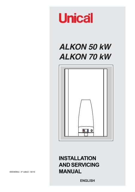
<strong>ALKON</strong> <strong>50</strong> kW<br />
<strong>ALKON</strong> <strong>70</strong> kW<br />
<strong>INST</strong>ALLATION<br />
AND SERVICING<br />
MANUAL<br />
ENGLISH
Warning: this manual contains instructions to be used exclusively by the<br />
installer and/or a competent person in accordance with the current laws in<br />
force.<br />
The end user MUST not make any alterations to the boiler.<br />
Failure to follow the instructions indicated in this manual, which is supplied<br />
with the boiler, could cause injury to persons, animals or damage to property.<br />
UNICAL shall not be held liable for any injury and/or damage.<br />
CONTENTS<br />
1 GENERAL INFORMATION ................................................................................................................................................................................... 3<br />
1.1 Symbols used in this guide .......................................................................................................................................................................... 3<br />
1.2 Correct use of the appliance ....................................................................................................................................................................... 3<br />
1.3 Water treatment ............................................................................................................................................................................................ 3<br />
1.4 IInformation to be passed over to the person in charge of the appliance ................................................................................................ 3<br />
1.5 Safety warnings ............................................................................................................................................................................................ 4<br />
1.6 Data badge .................................................................................................................................................................................................... 5<br />
1.7 General warnings ......................................................................................................................................................................................... 6<br />
2 TECHNICAL FEATURES AND DIMENSIONS ..................................................................................................................................................... 7<br />
2.1 Technical features ........................................................................................................................................................................................ 7<br />
2.2 Dimensions ................................................................................................................................................................................................... 8<br />
2.3 Main components ....................................................................................................................................................................................... 11<br />
2.4 Boiler water circuit ...................................................................................................................................................................................... 12<br />
2.5 Operating performances ............................................................................................................................................................................ 13<br />
2.6 General features ......................................................................................................................................................................................... 13<br />
3 <strong>INST</strong>RUCTIONS FOR THE <strong>INST</strong>ALLER ............................................................................................................................................................ 14<br />
3.1 General warnings ...................................................................................................................................................................................... 14<br />
3.2 Installation standards ................................................................................................................................................................................ 15<br />
3.3 Packaging .................................................................................................................................................................................................. 16<br />
3.4 Boiler location in a boiler room .................................................................................................................................................................. 16<br />
3.5 Installation on existing systems ............................................................................................................................................................... 17<br />
3.6 Gas connection ......................................................................................................................................................................................... 17<br />
3.7 Connection return and flow system pipes ............................................................................................................................................... 18<br />
3.8 Determination of primary boiler pump or boiler pump system.......................................................................................................... 19<br />
3.9 Supplemental safety, security and control devices ................................................................................................................................ 20<br />
3.10 Safety pressure relief valve ..................................................................................................................................................................... 21<br />
3.11 Working pressure...................................................................................................................................................................................... 21<br />
3.12 Mixing header filter .................................................................................................................................................................................... 22<br />
3.13 Mixing header ............................................................................................................................................................................................ 22<br />
3.14 <strong>Condensing</strong> drain ...................................................................................................................................................................................... 23<br />
3.15 Water treatment ......................................................................................................................................................................................... 24<br />
3.16 Fluing connections .................................................................................................................................................................................... 25<br />
3.17 Electrical connections ............................................................................................................................................................................... 30<br />
General warnings ...................................................................................................................................................................................... 30<br />
Connection to electrical supply 230V ...................................................................................................................................................... 30<br />
Room thermostat and/or heating controller E8 connection .................................................................................................................... 31<br />
Electrical connection of additional safety devices .................................................................................................................................. 31<br />
Electrical connection of additional safety devices for <strong>ALKON</strong> <strong>50</strong>/<strong>70</strong> in batterie ................................................................................... 32<br />
3.18 Practical connection diagrams ................................................................................................................................................................. 33<br />
3.19 Management connections diagram with E8 regulator ............................................................................................................................ 36<br />
3.20 Examples of installation (functional diagram) .......................................................................................................................................... 38<br />
3.21 Examples of installations with optional kits .............................................................................................................................................. 44<br />
3.22 Filling the system ...................................................................................................................................................................................... 48<br />
3.23 COMMISSIONING .................................................................................................................................................................................... 48<br />
Preliminary checks ................................................................................................................................................................................... 49<br />
Ignition and switching off ........................................................................................................................................................................... 49<br />
Information to be supplied to the user ..................................................................................................................................................... 49<br />
3.24 Burner adjustment ..................................................................................................................................................................................... <strong>50</strong><br />
3.25 Burner pressure adjustment .................................................................................................................................................................... 52<br />
3.26 Gas conversions....................................................................................................................................................................................... 52<br />
3.27 Programming of the operational parameters ........................................................................................................................................... 53<br />
4 SERVICING SCHEDULE .................................................................................................................................................................................... 55<br />
Instructions for checking and servicing the appliance ................................................................................................................................... 55<br />
Table of the resistance values in function of the heating and domestic sensor temperature ...................................................................... 55<br />
Verification and cleaning of the condensate evacuation siphon ..................................................................................................................... 55<br />
Sealing gasket between distributor and boiler body ........................................................................................................................................ 56<br />
5 FAULT FINDING ................................................................................................................................................................................................ 57<br />
5.1 Error codes ................................................................................................................................................................................................ 57<br />
5.2 Servicing Request ..................................................................................................................................................................................... 57<br />
5.3 Display off error codes on heating controller E8 .................................................................................................................................... 59<br />
6 DECLARATION OF CONFORMITY ............................................................................................................................................................... 62<br />
7 CE CERTIFICATE....................................................................................................................................................................................63<br />
2
1 GENERAL INFORMATION<br />
1.1 - SYMBOLS USED IN THIS GUIDE<br />
General Information<br />
When reading this guide particular care has to be given to the parts marked with the followings symbols:<br />
DANGER!<br />
Indicates serious danger<br />
for your personal safety<br />
and for your life<br />
1.2 - CORRECT USE OF THE APPLIANCE<br />
The <strong>ALKON</strong> appliance has been designed utilizing today’s heating technology and in compliance with the<br />
current safety regulations.However, following an improper use, dangers could arise for the safety and life<br />
of the user or of other people, or damage could be caused to the appliance or other objects.The appliance<br />
is designed to be used in pumped hot water central heating systems. Any other use of this appliance will be<br />
considered improper.UNICAL declines any responsibility for any damages or injuries caused by an improper<br />
use; in this case the risk is completely at the user’s responsibility.In order to use the appliance according<br />
to the scopes it was designed for it is essential to carefully follow the instructions indicated in this guide.<br />
1.3 - WATER TREATMENT<br />
WARNING!<br />
Indicates a potentially dangerous<br />
situation for the product and the<br />
environment<br />
• The hardness of the mains water supply conditions the frequency with which the heat exchanger is cleaned.<br />
• In hard water areas where the main water can exceed 15°f total hardness, a scale reducing device is<br />
recommended. The choice of this device has to be made taking into consideration the characteristics of<br />
the water.<br />
• In order to improve the resistance to lime scale it is recommended to adjust the domestic hot water temperature<br />
as near as possible to the one you really require.<br />
• We recommend you to check the state of cleanliness of the domestic hot water heat exchanger at the end of<br />
the first year and subsequently, on the basis of the lime scale found, this period can be extended to two years.<br />
1.4 - INFORMATION TO BE HANDED OVER TO THE USER<br />
NOTE!<br />
Suggestions for the<br />
user<br />
The user has to be instructed on the use and operation of his heating system, in particular:<br />
• Hand over these instructions to the end user, together with any other literature regarding this appliance,<br />
placed inside the envelope contained in the packaging. The user has to keep these documents in a safe<br />
place in order to always have them at hand for future reference.<br />
• Inform the user on the importance of air vents and of the flue outlet system, stressing the fact that is absolutely<br />
forbidden to make any alterations to the boiler.<br />
• Inform the user how to check the system’s water pressure as well as informing him how to restore the correct<br />
pressure.<br />
• Explain the function of time and temperature controls, thermostats, heating controls and radiators, to ensure<br />
the greatest possible fuel economy.<br />
• Remind the user that it is obligatory to carry out a comprehensive service annually and a combustion analysis<br />
every two years (in compliance with the national law).<br />
• If the appliance is sold or transferred to another owner or if the present user moves home and leaves the<br />
appliance installed, ensure yourself that the manual always follows the appliance so that it can be consulted<br />
by the new owner and/or installer.<br />
Failure to follow the instructions indicated in this guide, which is supplied with the boiler, could cause injury<br />
to persons, animals or damage to property. The manufacturer shall not be held liable for any such injury and/<br />
or damage.<br />
3
4<br />
General Information<br />
5 - SAFETY WARNINGS<br />
WARNING!<br />
The installation, adjustment, and servicing of this appliance must be carried out by a competent person and<br />
installed in accordance with the current standards and regulations. Failure to correctly install this appliance<br />
could cause injury to persons, animals or damage to property. The manufacturer shall not be held liable for<br />
any injury and/or damage.<br />
DANGER!<br />
Servicing or repairs of the appliance must be carried out by UNICAL authorised service technicians; UNICAL<br />
recommends drawing up a service contract. Bad or irregular servicing could compromise the safe operation<br />
of the appliance, and could cause injury to persons, animals or damage to property for which UNICAL shall not<br />
be held liable.<br />
Modifications to parts connected to the appliance<br />
Do not carry out any modifications to the following parts:<br />
- the boiler<br />
- to the gas, air, water supply pipes and electrical current<br />
- to the flue pipe, safety relief valve and its drainage pipe<br />
- to the constructive components which influence the appliance’s safe operation<br />
WARNING!<br />
When tightening or loosening the screw pipe connections, use only adequate fork spanners.<br />
The improper use and/or the use of inadequate equipment can cause damages (for example water or gas<br />
leakages).<br />
WARNING!<br />
Indications for appliances operating with propane gas<br />
Ensure yourself that before installing the appliance the gas tank has been purged.<br />
For a correct purging of the tank contact the liquid gas supplier or a competent person who has been legally<br />
authorized.<br />
If the tank has not been correctly purged problems could occur during ignition.<br />
If this occurs contact the liquid gas tank’s supplier.<br />
Smell of gas<br />
If you smell gas follow these safety indications:<br />
- Do not turn on or off electrical switches<br />
- Do no smoke<br />
- Do not use the telephone<br />
- Close the main gas tap<br />
- Open all windows and doors where the gas leakage has occurred<br />
- Inform the gas society or a company specialized in installing and servicing heating systems<br />
Explosive and easily inflammable substances<br />
Do not use or leave explosive or easily inflammable material (as for example: petrol, paint, paper) in the room<br />
where the appliance has been installed.
1.6 DATA BADGE<br />
CE Marking<br />
- The CE marking documents that the boilers satisfy:<br />
- The essential requirements of the Directive regarding gas appliances (Directive<br />
90/396/CEE)<br />
LEGEND:<br />
1 = CE Surveillance notify body<br />
2 = Boiler type<br />
3 = Boiler model<br />
4 = Number of stars (Directive 92/42/CEE)<br />
5 = (S.N°) Serial number<br />
6 = P.I.N. code<br />
7 = Approved fluing configurations<br />
8 = (N0x) N0x class<br />
A = Central Heating circuit features<br />
9 = (Pn) Nominal output<br />
10 = (Pcond) <strong>Condensing</strong> nominal output<br />
11 = (Qmax) Nominal heat input<br />
12 = (Adjusted Qn) Adjusted for nominal Heat input<br />
13 = (PMS) Max. pressure C.H. system<br />
14 = (T max) Max. C.H. temperature<br />
A<br />
B<br />
B = Domestic Hot Water circuit features<br />
15 = (Qnw) Nominal heat input in D.H.W. mode (if different from Qn)<br />
16 = (D) Specific D.H.W. flow rate according to EN 625 - EN 13203-1<br />
®<br />
3<br />
5<br />
2<br />
7 8<br />
13<br />
19<br />
9<br />
11<br />
15<br />
17<br />
C D<br />
E<br />
21 22<br />
27<br />
23<br />
General Information<br />
- The essential requirements of the ElectroMagnetic CompatibilityDirective<br />
(2004/108/CEE)<br />
- The essential requirements of the BoilersEfficiency Directive ( 92/42/CEE)<br />
- The essential requirements of the Low Voltage Directive ( 2006/95/CEE)<br />
14<br />
16<br />
18<br />
20<br />
10<br />
12<br />
24 25 26<br />
28<br />
17 = (R factor) N° taps based on the quantity of water declared EN<br />
13203-1<br />
18 = (F factor) N°stars based on the quality of water declared<br />
EN 13203-1<br />
19 = (PMW) Max. pressure D.H.W. system<br />
20 = (T max) Max. temperature D.H.W system<br />
C = Electrical features<br />
21 = Electrical power supply<br />
22 = Consumption<br />
23 = Protection grade<br />
D = Countries of destination<br />
24 = Direct and indirect country of destination<br />
25 = Gas family<br />
26 = Supply pressure<br />
E = Factory setting<br />
27 = Adjusted for gas type X<br />
28 = Space for national brands<br />
4<br />
6<br />
1<br />
5
6<br />
General Information<br />
1.7 - GENERAL WARNINGS<br />
This instruction manual is an integral and indispensable<br />
part of the product and must be retained by the person in<br />
charge of the appliance.<br />
Please read carefully the instructions contained in this manual<br />
as they provide important indications regarding the safe<br />
installation, use and servicing of this appliance.<br />
Keep this manual in a safe place for future reference.<br />
The installation and servicing must be carried out in<br />
accordance with the regulations in force according to the<br />
manufacturer’s instructions and by legally competent<br />
authorized persons.<br />
The installations for the domestic hot water production<br />
MUST be build, in their entirety, with materials (taps, pipes,<br />
fittings, etc.) approved for drinkable water.<br />
By a competent person, we imply a person who has a specific<br />
technical qualification in the field of components for central<br />
heating systems for domestic use, domestic hot water<br />
production and servicing. The person must have the<br />
qualifications foreseen by the current laws in force.<br />
Bad or irregular servicing could compromise the safe<br />
operation of the appliance, and could cause injury to persons,<br />
animals or damage to property. The manufacturer shall not<br />
be held liable for any such injury and/or damage.<br />
Before carrying out any cleaning or servicing turn off the<br />
electrical supply to the boiler by means of the ON/OFF switch<br />
and/or by means of the appropriate shutdown devices.<br />
Do not obstruct the intake/outlet terminal ducts.<br />
In the event of failure and/or faulty functioning of the appliance,<br />
switch off the boiler. Do not attempt to make any repairs:<br />
contact qualified technicians.<br />
Any repairs must be carried out by <strong>Unical</strong> authorized<br />
technicians and using only original spare parts. Nonobservance<br />
of the above requirement may jeopardize the<br />
safety of the appliance.<br />
To guarantee the efficiency and correct functioning of the<br />
appliance it is indispensable to have the boiler serviced<br />
annually by a qualified person.<br />
If the boiler remains unused for long periods, ensure that any<br />
dangerous parts are rendered innocuous.<br />
Before putting again into service an appliance which has been<br />
unused for a certain time, proceed to rinse the domestic hot<br />
water circuit, making the water flowing for the time necessary<br />
to draw the full content of the domestic circuit.<br />
If the appliance is sold or transferred to another owner or if<br />
the present user moves home and leaves the appliance<br />
installed, ensure yourself that the manual always follows the<br />
appliance so that it can be consulted by the new owner and/<br />
or installer.<br />
Only original accessories must be used for all appliances<br />
supplied with optionals or kits (including electrical ones).<br />
This appliance must be used only for the purposes for which<br />
it has been expressively designed. Any other use shall be<br />
considered incorrect and therefore dangerous.
2<br />
2.1 - TECHNICAL FEATURES<br />
The <strong>ALKON</strong> <strong>50</strong>/<strong>70</strong> boilers are a thermals gas fired units with<br />
an atmospheric fully pre-mixed burner.<br />
They are supplied only in heating version.<br />
These boilers have an input head power of: <strong>50</strong> or <strong>70</strong> kW,<br />
These boilers are designed for use on gas category II2H3P.<br />
The <strong>ALKON</strong> boilers are supplied complete with all the safety<br />
and control devices in accordance with all the current<br />
regulations and the following European directives:<br />
– Gas Directive 90/396 CEE<br />
– Efficiency Directive 92/42 CEE<br />
– Electromagnetic Compatibility Directive 2004/108 CEE<br />
– Low Voltage Directive 2006/95 CEE.<br />
Moreover, the boilers of the <strong>ALKON</strong> range are classified as<br />
“CONDENSING BOILERS” according to the Directive 92/42<br />
CEE appendix 2 (4 stars).<br />
DESCRIPTION OF COMPONENTS AND FEATURES:<br />
• Aluminium heat exchanger/condenser;<br />
Fully premixed burner working at constant CO2;<br />
Electronic ignition;<br />
Safety high limit thermostat;<br />
Flow temperature sensor;<br />
Return temperature sensor;<br />
930<br />
TECHNICAL FEATURES<br />
AND DIMENSIONS<br />
2.2 - DIMENSIONS<br />
615<br />
R CH system return 1’’ (1 ¼’’ for <strong>70</strong> kW)<br />
M CH flow system 1’’ (1 ¼’’ for <strong>70</strong> kW)<br />
G Gas Inlet Ø ¾’’<br />
Sc Outlet condensate drain siphon (corpo alluminio)<br />
Technical features and dimensions<br />
266<br />
Automatic air vent;<br />
Drain condensate siphon<br />
Control panel with electrical protection IP X4D;<br />
eBUS device;<br />
CH temperature selector switch: 30 ÷ 85°C;<br />
Flame modulation in function of the absorbed power;<br />
Pump overrun function;<br />
Additional functions : diagnostics of operation parameters<br />
and troubles, antifreeze, technical functions and digital indication<br />
of failures.<br />
Constant combustion ratio<br />
Self adapting output depending on the length of flue ducts<br />
Modulating pump for <strong>ALKON</strong> <strong>70</strong><br />
OPTIONAL KITS:<br />
Kit of manidold for additional safety devices<br />
• Kit of additional safety devices<br />
• Krömschröder controller E8/Expansion modules and<br />
modulating thermostats<br />
(case for wall mounting)<br />
• Kit of boiler pump (at constant or modulating flow rate:<br />
only for <strong>ALKON</strong> <strong>50</strong>)<br />
• Mixing bottle Kit<br />
• Chimney for single, battery or cascade mounting<br />
• Supporting frames<br />
• Kit for D.H.W. priority<br />
• Kit of blind flanges and hydraulic manifolds<br />
• Kit of wiring harness for external D.H.W. tank<br />
135<br />
VIEW FROM ABOVE<br />
430 107<br />
VIEW FROM BELOW<br />
180<br />
SV<br />
R M G<br />
78<br />
Sc Scf<br />
85 110 110 132 100 78<br />
A<br />
S<br />
125<br />
179<br />
78<br />
Scf Outlet condensate drain siphon (proveniente dal tubo scarico fumi)<br />
SV Safety valve outlet<br />
A Air intake<br />
S Flue Outlet<br />
266<br />
7
8<br />
Technical features and dimensions<br />
DIMENSIONS <strong>ALKON</strong> <strong>50</strong>/<strong>70</strong> + KIT SAFETY DEVICES + HYDRAULIC HEADER +Y FILTER KIT<br />
762<br />
<strong>50</strong>2<br />
712<br />
DIMENSIONS <strong>ALKON</strong> <strong>50</strong>/<strong>70</strong> in BATTERY (n.2 boilers) + KIT SAFETY DEVICES + HYDRAULIC HEADER +Y FILTER KIT<br />
1740<br />
1<strong>50</strong>0<br />
<strong>50</strong>0<br />
1510<br />
3040<br />
1978<br />
1972<br />
2431
1740<br />
Technical features and dimensions<br />
DIMENSIONS <strong>ALKON</strong> <strong>50</strong>/<strong>70</strong> in BATTERY (n.3 boilers) + KIT SAFETY DEVICES + HYDRAULIC HEADER +Y FILTER KIT<br />
1740<br />
1<strong>50</strong>0<br />
<strong>50</strong>0<br />
DIMENSIONS <strong>ALKON</strong> <strong>50</strong>/<strong>70</strong> in BATTERY (n.4 boilers) + KIT SAFETY DEVICES + HYDRAULIC HEADER +Y FILTER KIT<br />
1<strong>50</strong>0<br />
<strong>50</strong>0<br />
3726<br />
4630<br />
1972<br />
2475<br />
1972<br />
2510<br />
9
10<br />
Technical features and dimensions<br />
2.3 - MAIN COMPONENTS<br />
<strong>ALKON</strong> <strong>50</strong><br />
AIR<br />
VENT<br />
VALVE<br />
IGNITION<br />
ELECTRODE<br />
IGNITION<br />
TRANSFORMER<br />
OVERHEAT<br />
THERMOSTAT<br />
FLOW<br />
TEMPERATURE<br />
SENSOR<br />
GAS VALVE<br />
RETURN<br />
TEMPERATURE<br />
SENSOR<br />
SPACER PIPE<br />
REPLACEABLE<br />
FOR MOUNTING<br />
OF OPTIONAL<br />
CIRCULATOR<br />
SAFETY VALVE<br />
MODULATING<br />
FAN<br />
MIN. WATER<br />
PRESSURE<br />
SWITCH<br />
N.B.:<br />
The boiler cannot work on natural circulation<br />
AIR INTAKE<br />
OPENING<br />
(Ø80 mm)<br />
CONDENSATE<br />
DRAIN<br />
(Ø25 mm)<br />
FLUE<br />
OUTLET<br />
PIPE<br />
(Ø80 mm)<br />
ALUMINIUM HEAT<br />
EXCHANGER/<br />
CONDENSER<br />
PIPE WITH<br />
SMOKE<br />
SAMPLING AND<br />
CONDENSATE<br />
EVACUATION<br />
CONNECTION<br />
SIPHON
<strong>ALKON</strong> <strong>70</strong><br />
AIR<br />
VENT<br />
VALVE<br />
IGNITION<br />
ELECTRODE<br />
IGNITION<br />
TRANSFORMER<br />
OVERHEAT<br />
THERMOSTAT<br />
FLOW<br />
TEMPERATURE<br />
SENSOR<br />
GAS VALVE<br />
RETURN<br />
TEMPERATURE<br />
SENSOR<br />
MODULANTING<br />
PUMP<br />
SAFETY VALVE<br />
MODULATING<br />
FAN<br />
MIN. WATER<br />
PRESSURE<br />
SWITCH<br />
Technical features and dimensions<br />
AIR INTAKE<br />
OPENING<br />
(Ø80 mm)<br />
CONDENSATE<br />
DRAIN<br />
(Ø25 mm)<br />
FLUE<br />
OUTLET<br />
PIPE<br />
(Ø80 mm)<br />
ALUMINIUM HEAT<br />
EXCHANGER/<br />
CONDENSER<br />
PIPE WITH<br />
SMOKE<br />
SAMPLING AND<br />
CONDENSATE<br />
EVACUATION<br />
CONNECTION<br />
SIPHON<br />
11
12<br />
Technical features and dimensions<br />
2.4 - BOILER WATER CIRCUIT DIAGRAM<br />
3<br />
13<br />
2<br />
5<br />
8<br />
7<br />
14<br />
15<br />
R M<br />
G<br />
4<br />
ATTENTION!<br />
THE PRE-FORMING FOR THE BOILER PUMP IS<br />
ONLY FOR THE PUMP KIT SUPPLIED BY<br />
UNICAL<br />
00361320 - Kit of MODULATING PUMP, only for<br />
<strong>ALKON</strong> <strong>50</strong><br />
00361321 - Kit of CONSTANT FLOW RATE PUMP, only for<br />
<strong>ALKON</strong> <strong>50</strong><br />
6<br />
1<br />
10<br />
11<br />
12<br />
9<br />
1 Gas valve<br />
2 CH flow temperature sensor<br />
3 CH return temperature sensor<br />
4 Condensate drain siphon<br />
5 Overheat thermostat<br />
6 Heat exchanger<br />
7 Burner<br />
8 Air vent valve<br />
9 Flue outlet / Air intake<br />
10 Fan<br />
11 Premix<br />
12 Room sealed chamber<br />
13 Replaceable pipe for insertion optional pump<br />
(only for <strong>ALKON</strong> <strong>50</strong>)<br />
modulating pump only for <strong>ALKON</strong> <strong>70</strong><br />
14 Safety valve 6 bar<br />
15 Pressure switch against lack of water<br />
M C.H flow<br />
G Gas supply<br />
R C.H. return
2.5 - PERFORMANCE DATA<br />
2.6 - GENERAL FEATURES<br />
Appliance’s family gas category<br />
Min. water flow rate in CH circuit (Δt 20 °C)<br />
Min. pressure in CH circuit<br />
Max. pressure in CH circuit<br />
Min. dynamic gas pressure (natural gas)<br />
Water content in primary circuit<br />
Max operating temp. in CH mode<br />
Min operating temp. in CH mode<br />
Total volume CH expansion vessel<br />
Total pre-loading expansion vessel<br />
Max water content CH circuit (calculated for a max temp. of 82°C)<br />
Min flow rate DHW circuit<br />
Min. DHW inlet pressure<br />
Max DHW inlet pressure<br />
DHW specific flow rate ( t 30 °C)<br />
DHW flow restrictor<br />
DHW production in continuous operation with t 45 K<br />
DHW production in continuous operation with t 40 K<br />
DHW production in continuous operation with t 35 K<br />
DHW production in continuous operation with t 30 K (*)<br />
DHW production in continuous operation with t 25 K (*)<br />
DHW adjustable temperature<br />
Electrical supply /power consumption<br />
Fuse rating<br />
Maximum absorbed power (with optional modulating pump)<br />
Electrical protection<br />
Net weight<br />
Technical features and dimensions<br />
For information regarding the adjustment of: INJECTORS - BURNER PRESSURES – DIAPHRAGMS – OUTPUTS – GAS CONSUMPTIONS please refer to<br />
the paragraph ADAPTMENT TO THE USE OF OTHER GASES.<br />
Max heat input<br />
Min heat input<br />
Nominal heat outpout 80/60<br />
Minimum heat output 80/60<br />
Efficiency at nominal load 80/60<br />
Efficiency at minimal load 80/60<br />
Number of stars (according to CEE 92/42<br />
Nominal heat output in condensing mode <strong>50</strong>/30<br />
Minimal heat output in condensing mode <strong>50</strong>/30<br />
Efficiency at nominal load in condensing mode <strong>50</strong>/30<br />
Efficiency at minimal load in condensing mode <strong>50</strong>/30<br />
Combustion efficiency at nominal load<br />
Combustion efficiency at minimal load<br />
Stand-by losses with burner in operation<br />
Stand-by losses with burner off<br />
(*) Flue gas temperature tf-ta (max)<br />
Flue gas mass flow rate (max)<br />
Air excess λ<br />
Condensate production max<br />
(**) CO (min - max)<br />
2<br />
CO at 0% of O (min - max)<br />
2<br />
N0x (value according to EN 297/A3 and EN 483<br />
N0x class<br />
Flue losses with burner in operation (max)<br />
(*) Room Temperature = 20°C<br />
(**) See Table Injectors - Pressures<br />
kW<br />
kW<br />
kW<br />
kW<br />
%<br />
%<br />
n.<br />
kW<br />
kW<br />
%<br />
%<br />
%<br />
%<br />
%<br />
%<br />
°C<br />
g/s<br />
%<br />
kg/h<br />
%<br />
mg/kWh<br />
mg/kWh<br />
%<br />
mg/kWh<br />
l/min<br />
bar<br />
bar<br />
mbar<br />
l<br />
°C<br />
°C<br />
l<br />
bar<br />
l<br />
l<br />
bar<br />
bar<br />
l/min.<br />
l/min.<br />
l/min.<br />
l/min.<br />
l/min.<br />
l/min.<br />
l/min.<br />
°C<br />
V-Hz<br />
A (F)<br />
W<br />
IP<br />
kg<br />
<strong>ALKON</strong> <strong>50</strong> <strong>ALKON</strong> <strong>70</strong><br />
48,5<br />
9,6<br />
47,2<br />
9,1<br />
97,29<br />
94,9<br />
4<br />
49,3<br />
10,3<br />
101,62<br />
107,33<br />
97,80<br />
98,42<br />
0,58<br />
0,311<br />
43,6<br />
21,44<br />
26,84<br />
7,8<br />
-<br />
19,7 - 71,5<br />
33,9<br />
5<br />
2,20<br />
<strong>ALKON</strong> <strong>50</strong><br />
II2H3P 3,86<br />
0,5<br />
6<br />
10<br />
3,9<br />
85<br />
30<br />
-<br />
-<br />
-<br />
-<br />
-<br />
-<br />
-<br />
-<br />
-<br />
-<br />
-<br />
-<br />
-<br />
-<br />
230/<strong>50</strong><br />
4<br />
77 (172)<br />
X4D<br />
<strong>50</strong><br />
67,5<br />
9,6<br />
65,5<br />
9,1<br />
97,06<br />
94,9<br />
4<br />
68,5<br />
10,3<br />
101,51<br />
107,33<br />
98,39<br />
98,28<br />
0,35<br />
0,223<br />
51,3<br />
30,96<br />
26,84<br />
10,87<br />
-<br />
19,7 - 98,7<br />
34,68<br />
5<br />
2,59<br />
(Reference gas: Natural Gas G20)<br />
<strong>ALKON</strong> <strong>70</strong><br />
II2H3P 5,4<br />
0,5<br />
6<br />
10<br />
3,9<br />
85<br />
30<br />
-<br />
-<br />
-<br />
-<br />
-<br />
-<br />
-<br />
-<br />
-<br />
-<br />
-<br />
-<br />
-<br />
-<br />
230/<strong>50</strong><br />
4<br />
145 (290)<br />
X4D<br />
13
14<br />
Instructions for the installer<br />
3<br />
<strong>INST</strong>RUCTIONS FOR<br />
THE <strong>INST</strong>ALLER<br />
3.1 - GENERAL WARNINGS<br />
WARNING!<br />
This boiler has to be destined for the use for<br />
which it has been expressively designed for.<br />
Any other use shall be considered improper<br />
and therefore dangerous.<br />
This boiler is designed to heat water at a<br />
temperature inferior to boiling point at an<br />
atmospheric pressure.<br />
WARNING!<br />
These appliances are exclusively designed<br />
to be installed inside adequate boiler rooms.<br />
Therefore these appliances must not be<br />
installed and operated externally. An outdoor<br />
installation could cause malfunctioning and<br />
could be dangerous. For external<br />
installations, it is recommended to use<br />
appliances which are specifically designed<br />
and predisposed for this purpose.<br />
Before installing the boiler the following points<br />
have to be carried out by a competent engineer:<br />
a) The whole system should be thoroughly<br />
flushed in order to remove any residual dirt or<br />
grime which could compromise the correct<br />
boiler operation.<br />
b) Check that the boiler has been preset for<br />
operating with the gas type available.<br />
This is verifiable via the indication on the<br />
packaging and on the data badge;<br />
c) Check that the chimney/flue pipe has an<br />
adequate draught,does not have any<br />
constrictions, and that no other appliance’s<br />
flue outlets have been fitted, unless the chimney<br />
is serving more than one heating appliance,<br />
according to the specific standards and<br />
regulations in force.<br />
The connection between the boiler and<br />
chimney/flue outlet can be made only after this<br />
verification has been carried out.<br />
WARNING!<br />
In rooms where there is the presence of<br />
aggressive vapours or dust the appliance<br />
must operate independently from the air<br />
present in the boiler’s location room, i.e. only<br />
in Type C version.<br />
WARNING!<br />
The appliance must be installed by a qualified<br />
engineer, who complies to the technicalprofessional<br />
requirements, who, under his<br />
own responsibility, guarantees the<br />
compliance of the standards according to<br />
the latest regulations.<br />
WARNING!<br />
The appliance must be installed only on a<br />
closed, vertical flat wall, made of non<br />
combustible material.<br />
The appliance must be positioned so that at<br />
least the minimum operational and servicing<br />
clearances are provided.<br />
The boiler must be connected to a heating<br />
system which is compatible to its performance<br />
and output.
3.2 - STANDARD CODES FOR<br />
<strong>INST</strong>ALLATION<br />
The appliance must be installed in compliance to the<br />
instructions contained in this manual.<br />
The installation must be carried out by a competent qualified<br />
engineer, whom will assume the responsibility of complying<br />
to all the local and/or national regulations published in the<br />
official publications, as well as all the applicable codes of<br />
practice.<br />
Before installing the appliance please contact the gas supply<br />
company.<br />
The installation must be carried out in accordance to the codes<br />
of practice, the regulations and the requirements hereby<br />
indicated which constitute an indicative list, but not a complete<br />
one, as these continue to undergo revisions.<br />
Instructions for the installer<br />
Moreover, the boiler must be installed in accordance to all the<br />
regulations regarding the boiler room, the building regulations<br />
and the prescriptions regarding central heating plants in force<br />
in the country the boiler is installed.<br />
The appliance must be installed, commissioned and serviced<br />
according to the regulations in force. This is also valid for the<br />
hydraulic system, the flue outlet system and the boiler house.<br />
15
16<br />
Instructions for the installer<br />
3.3 - PACKAGING<br />
The <strong>ALKON</strong> <strong>50</strong>/<strong>70</strong> boiler is supplied fully assembled in a<br />
strong cardboard box.<br />
Special attention shall be paid to local regulations and laws<br />
about boiler houses and particularly to the obligation of<br />
keeping minimum clearances and empty space around the<br />
boiler. The installation shall be in compliance with all latest<br />
regulations and laws about boiler houses, installations of<br />
heating and hot-water systems, ventilation, chimneys capable<br />
of evacuating the flue gases of condensing boilers and any<br />
other applicable requirement.<br />
When selecting the position for the installation of the boiler<br />
please comply to the following safety requirements:<br />
Guarantee an easy access to the components of the boiler<br />
to facilitate the possible operations of ordinary and extraordinary<br />
maintenance.<br />
Fit the appliance in rooms protected from frost;<br />
In rooms where aggressive vapours or dust are present,<br />
the appliance must be able to operate independently from<br />
the air of the location room;<br />
The appliance must be installed exclusively on a vertical<br />
and solid wall, capable of adequately supporting the weight<br />
of the boiler;<br />
The wall must not be made of inflammable material.<br />
CONNECTIONS <strong>ALKON</strong> <strong>50</strong> <strong>ALKON</strong> <strong>70</strong><br />
M = CH system flow 1” 1’’¼<br />
R = CH system return 1” 1’’¼<br />
G = Gas Supply 3/4” 3/4”<br />
S = Condensate Drain<br />
After having unpacked the boiler check that it is<br />
intact and undamaged.<br />
Keep the packaging material (cardboard box,<br />
plastic bags, polyester protection etc.) out of<br />
the reach of children as they can be<br />
dangerous.<br />
UNICAL refuses all liability for injury to persons,<br />
animals or damage to property deriving from<br />
not having respected the above mentioned<br />
recommendations.<br />
In the packaging, in addition to the boiler, you can also find<br />
the following contents:<br />
- Service logbook<br />
- Instruction manual for the person in charge of the<br />
appliance<br />
- Instruction manual for the installer and servicing personnel<br />
- Warranty<br />
- Nr. 2 spare parts request coupons<br />
840<br />
3<strong>70</strong><br />
3.4 - BOILER LOCATION INSIDE A BOILER HOUSE<br />
715<br />
R M G<br />
85 110 110<br />
7<br />
132<br />
1025<br />
- N° 3 plastic plugs for fixing boiler<br />
- Boiler support bracket<br />
- Condensate evacuation siphon<br />
- Aluminum pipe Ø 80 mm for smoke evacuation<br />
310,5 206,5<br />
S<br />
177
3.5 - <strong>INST</strong>ALLATION ON EXISTING<br />
HEATING SYSTEMS<br />
When the appliance is installed on existing systems, ensure<br />
yourself that:<br />
- The flue outlet pipe is suitable for condensing boilers, for<br />
the temperature of the products of combustion, calculated<br />
and manufactured according to the regulations in force. It<br />
must be installed as much as possible in a straight line,<br />
tested for soundness, insulated and must not have any<br />
occlusions or restrictions.<br />
- The flue outlet pipe has a connection for the discharge of<br />
condensate.<br />
3.6 - GAS CONNECTION<br />
The gas supply pipe must be connected to the boiler via the<br />
respective pipe connection ¾” as indicated on page 13.<br />
The gas supply pipe must have a section which is identical or<br />
greater then the one used on the boiler and must assure a<br />
correct gas pressure.<br />
It is however important to comply with the specific norms and<br />
requirements in force, foreseeing on-off valves, gas filter,<br />
anti-vibrating joint etc.<br />
Before commissioning an internal gas distribution system<br />
and therefore before connecting it to the gas meter, the<br />
complete installation must be tested for gas soundness.<br />
If any part of the system is concealed from view the gas<br />
soundness test must be carried out before covering the pipes.<br />
DANGER!<br />
The gas connection must be carried out by a<br />
registered engineer who will have to respect<br />
and comply to the regulations in force and to<br />
the requirements indicated by the local gas<br />
supplier. An incorrect installation could<br />
cause injury to persons, animals or damage<br />
to property. The manufacturer shall not be<br />
held liable for any injury and/or damage.<br />
1. On-off gas supply valve<br />
2. Double membrane regulator<br />
3. Gas filter<br />
4. Anti-vibrating joint<br />
5. Selenoid valve<br />
6. On-off cock<br />
EXAMPLE OF A GAS SUPPLY SYSTEM<br />
INSIDE<br />
BOILER<br />
ROOM<br />
Instructions for the installer<br />
- The boiler room has a suitable outlet for the discharge of<br />
condensate produce by the boiler.<br />
- The electrical system has been fitted in compliance to the<br />
specific norms and the work has been carried out by a<br />
competent person.<br />
- The circulation pump’s output, the head and flow direction<br />
are suitable.<br />
- The gas feeding supply pipe and the eventual tank are<br />
constructed according to the regulations in force.<br />
- The expansion vessels assure the total absorption of the<br />
dilatation of the fluid contained in the system.<br />
- The system has been cleaned of impurities and lime scale.<br />
1 2 3 4 6<br />
5 6<br />
Before installing the boiler it is recommended<br />
to thoroughly clean all the supply piping in order<br />
to remove any eventual residual grime which<br />
could compromise the boilers correct<br />
functioning.<br />
If you smell gas:<br />
a. Do not turn on or off electrical switches, use<br />
the telephone or any other object which can<br />
provoke sparks;<br />
b. Open all doors and windows in order to<br />
allow fresh air to enter and purify the room;<br />
c. Close all gas cocks<br />
d. Contact a service engineer, qualified<br />
installer or the gas supply company.<br />
As a safety measure against gas leaks, <strong>Unical</strong><br />
recommends installing a surveillance and<br />
protective system made up of a gas leakage<br />
detector combined with an on-off selenoid<br />
valve on the gas supply line.<br />
OUTSIDE<br />
BOILER<br />
ROOM<br />
17
18<br />
Instructions for the installer<br />
3.7 - FLOW AND RETURN PIPE CONNEC-<br />
TIONS<br />
The CH flow and return circuits have to be connected to the<br />
boiler via the respective connections 1” or 1’’¼ as indicated<br />
on page 16.<br />
When determining the size of the CH circuit pipes it is<br />
essential to bear in mind the pressure losses induced by any<br />
of the system’s components and by the configuration of the<br />
same system.<br />
The route of the piping has to be conceived taking all the<br />
necessary precautions in order to avoid air locks and to<br />
facilitate the continuous purging of the system.<br />
WARNING!<br />
Before installing the boiler we recommend<br />
that the system is flushed out with a suitable<br />
product, in order to eliminate any metallic<br />
tooling or welding residues, oil and grime<br />
which could reach the boiler and affect the<br />
proper running of the boiler.<br />
Non-observance of these instructions could<br />
cause injury to persons, animals or damage<br />
to property. The manufacturer shall not be<br />
held liable for any such injury and/or damage.<br />
Ensure yourself that the system’s piping is not<br />
used as the earth clamps for the electrical or<br />
telephonic system. They are absolutely<br />
unsuitable for this use. In a short time this could<br />
cause serious damage to the piping, boiler<br />
and radiators.<br />
R<br />
M<br />
GATE<br />
VALVES<br />
WARNING!<br />
IT IS ABSOLUTELY FORBIDDEN TO FIT ON-OFF<br />
VALVES ON THE GENERATOR TO THE FORE<br />
OF THE SAFTEY DEVICES
Pressure losses (mmH2O)<br />
Instructions for the installer<br />
3.8 - DETERMINATION OF PRIMARY BOILER PUMP OR BOILER SYSTEM PUMP<br />
The boiler pump must have a delivery head which can ensure<br />
the water flow rate as shown in the diagram “Water pressure<br />
losses”.<br />
The following table gives an indication of the pump’s flow rate<br />
in function of the Ät of the primary circuit if the installation has<br />
a mixing header<br />
Power supply in kW<br />
Max flow rate<br />
demanded in l/h (ΔT 15K)<br />
Portata nominale<br />
richiesta in l/h (Δ T 20K)<br />
8000<br />
7800<br />
7600<br />
7400<br />
7200<br />
<strong>70</strong>00<br />
6800<br />
6600<br />
6400<br />
6200<br />
6000<br />
5800<br />
5600<br />
5400<br />
5200<br />
<strong>50</strong>00<br />
4800<br />
4600<br />
4400<br />
4200<br />
4000<br />
3800<br />
3600<br />
3400<br />
3200<br />
3000<br />
2800<br />
2600<br />
2400<br />
2200<br />
2000<br />
1800<br />
1600<br />
1400<br />
1200<br />
1000<br />
800<br />
600<br />
400<br />
200<br />
0<br />
<strong>ALKON</strong> <strong>50</strong><br />
<strong>ALKON</strong> <strong>50</strong><br />
49,3<br />
2826<br />
2120<br />
<strong>ALKON</strong> <strong>70</strong><br />
68,5<br />
3927<br />
2946<br />
WATER SIDE PRESSURE LOSSES<br />
<strong>ALKON</strong> <strong>70</strong><br />
0 200 400 600 800 1000 1200 1400 1600 1800 2000 2200 2400 2600 2800 3000 3200 3400 3600<br />
Q: water flow rate (l/h)<br />
The size of the pumps must be determined<br />
by installers or technical engineers<br />
according to boiler data and system<br />
design.<br />
The water side resistance curve of the<br />
boiler is shown in the following diagram.<br />
The pump is not an integral part of the<br />
boiler.<br />
It is recommended to choose a pump with<br />
the rate and delivery head at about 2/3 of<br />
its characteristic heating curve.<br />
3800 4000 4200 4400 4600 4800 <strong>50</strong>00<br />
For a ΔT 20 K, the max. water flow rate requested is 2120 l/h.<br />
From the graph of the boiler’s pressure losses, it can be determined that the pump must be able<br />
to guarantee a delivery head of at least 1,6 mH2O.<br />
NOTE: The use of a mixing header fitted between the boiler circuit and the system circuit is<br />
always advisable. It becomes INDISPENSABLE if the system requires flow rates superior to the<br />
maximum permitted boiler flow rates, which is to say lower than 15K.<br />
19
20<br />
Instructions for the installer<br />
3.9 - SUPPLEMENTAL SAFETY, PROTECTIVE AND CONTROL DEVICES PRESCRIBED BY<br />
THE GOVERNMENT DECREE 01-12-1975 AND RELATIVE APPLICABLE TECHNICAL<br />
SPECIFICATIONS (CONTAINED IN THE “RACCOLTA R EDITION 1982”)<br />
CERTIFICATION OF THE SUPPLEMENTAL SAFETY DEVICES:<br />
Several notified bodies prescribe supplemental safety<br />
devices.<br />
For the safety valves and on-off gas valves it is necessary to<br />
obtain the ISPESL (Institution for preventive measures and<br />
safety at work) calibration certificate which confirms that they<br />
are free from lead or bossing.<br />
The expansion vessels with a capacity superior to 24 litres<br />
must have be supplied with an approval booklet released by<br />
ISPESL and a manufacturers conformity declaration.<br />
All the accessories must have an ISPESL approval certificate.<br />
SAFETY DEVICES<br />
1. On-off gas valve: a device which has the function of cutting<br />
off the gas supply when the water temperature reaches the<br />
max. predetermined value. The sensible element has to be<br />
installed as nearest as possible to the generator (flow pipe)<br />
at a distance which has to be < <strong>50</strong>0 mm and must not be able<br />
to be cut-off.<br />
2. Pressure relief valve: it has the function of discharging<br />
in the atmosphere the fluid contained in the generator when<br />
this has, for whatever motive, reached the maximum working<br />
pressure.<br />
PROTECTIVE DEVICES<br />
3. Overheat thermostat: it has the function of shutting down<br />
the generator if the safety thermostat fitted in the boiler<br />
malfunctions. It must be calibrated to a value of < 100°C,<br />
which MUST not be changed.<br />
4. Safety pressure switch: it has the function of shutting<br />
down the generator if it reaches the maximum working<br />
pressure. It must be able to be reset manually.<br />
CONTROL DEVICES<br />
5. Pressure indicator with shock absorber tube and<br />
pressure gauge holder valve: it indicates the effective<br />
pressure existing in the generator. It must be graduated in<br />
“bar” and must have the maximum operating pressure in<br />
scale and be equipped with a 3-way valve with the connection<br />
for the manometer.<br />
6. Thermometer: it indicates the effective water temperature<br />
contained in the generator. It must be graduated in degrees<br />
Celsius with a temperature scale not exceeding 120°C.<br />
7. Bulb holder for a master temperature gauge: it must<br />
be fitted vertically and must have an inside dia. of 10 mm,<br />
in order to locate a mercury master thermometer.<br />
8. Calibrated expansion vessel: it permits the absorption<br />
of the increase in volume of the system’s water following an<br />
increase in temperature and its nominal maximum working<br />
pressure must be higher than the pressure relief valve’s<br />
setting.<br />
6<br />
1<br />
4<br />
6 7<br />
7<br />
3<br />
For the electrical connection of the<br />
additional safety devices make reference<br />
to the paragraph 3.17 - Connection of the<br />
additional safety devices.<br />
5<br />
9<br />
8<br />
2
3.10 - PRESSURE RELIEF VALVE DRAIN<br />
PIPE<br />
A pressure relief valve must be fitted on the flow<br />
pipe, within 0,5 m from the boiler. It must be<br />
dimensioned for the capacity of the boiler and<br />
must comply to the regulations in force,<br />
WARNING!<br />
Please remember that it is forbidden to<br />
interpose, between the boiler and the<br />
pressure relief valve, any type of cutting-off<br />
device. Moreover it is recommended to use<br />
cutting-off valves which do not exceed the<br />
maximum allowable operating pressure.<br />
WARNING!<br />
In correspondence to the heating pressure relief valve<br />
foresee the installation of a discharge pipe with a funnel<br />
and a siphon which lead to an adequate drainage. The<br />
drainage has to be controllable by sight.<br />
If this precaution is not made, an eventual intervention of<br />
the pressure relief valve could cause injury to persons,<br />
animals or damage to property. The manufacturer shall<br />
not be held liable for any injury and/or damage.<br />
3.11 - WORKING PRESSURE<br />
The boiler’s maximum allowable working pressure is set at<br />
3 bar; whilst the minimum pressure is pre-charged to 0,5 bar.<br />
WARNING!<br />
The boiler doesn‘t integrate any specific<br />
device against the lack of water, because<br />
this function is performed by the high limit<br />
thermostat (overheating).<br />
Note: On the main PCB it is alwys possible to electrically<br />
connect a minimum water pressure switch against the lack<br />
of water.<br />
Instructions for the installer<br />
21
22<br />
Instructions for the installer<br />
3.12 - MIXING HEADER FILTER<br />
UNICAL suggests the installation of a Y filter<br />
on the return pipe so that it can be cleaned if<br />
necessary.<br />
This filter will protect the boiler from the heating<br />
system dirt.<br />
3.13 - MIXING HEADER<br />
(cod. 00361333-00361499-00361<strong>50</strong>0)<br />
In order to ensure correct boiler operation it is necessary to<br />
use a mixing header which guarantees:<br />
- the separation and collection of circuit dirt<br />
- optimal air venting<br />
- hydraulic de-coupling of the two hydraulic circulation<br />
circuits<br />
- balancing of the circuits
3.14 - CONDENSATE DRAIN<br />
During the combustion process the boiler produces<br />
condensate which, through the “A” pipe, flows into the siphon.<br />
The condensate which forms inside the boiler has to be routed<br />
into an adequate drain by means of the pipe “B”.<br />
DANGER!<br />
Before commissioning the appliance fill the<br />
siphon and check the correct drainage of the<br />
condensate.<br />
If the appliance is used with the condensate<br />
drain siphon empty there could be danger of<br />
intoxication resulting from the escape of flue<br />
gasses.<br />
The connection between the appliance and the sewage<br />
system must be carried out in compliance with the specific<br />
reference standards, and in particular:<br />
- prevent the end user utilizing the condensate produced;<br />
- a siphon must be fitted (supplied with the boiler);<br />
- there must be no bottlenecks;<br />
- the connection must be made just under the bottom part of<br />
the boiler;<br />
- it must be installed so as to avoid freezing of the liquid<br />
when the boiler is operating and prevent the eventual pressurization<br />
of the sewage system;<br />
- consent the correct downflow of the appliance’s liquid discharges;<br />
- it must be made with one of the following materials which<br />
are resistant to condensate:<br />
- Grès, according to the Standards DIN 1230-1 and 6, EN<br />
295-1 or 2 or 3;<br />
- Glass (boron silicate);<br />
- Polyvinyl chloride (PVC) , according to DIN V 19534-1<br />
and 2, and DIN 19538;<br />
- Polyethylene (PE) DH type, according to DIN 19535-1<br />
and 2 and DIN 19537-1 and 2;<br />
- Polypropylene (PP) and copolymer styrene (ABS) according<br />
to DIN V 19561;<br />
- Polyesterific resin (GF-UP), according to DIN 19565-1;<br />
- Stainless steel.<br />
Instructions for the installer<br />
B<br />
Condensate<br />
drain pipe of<br />
boiler and<br />
chimney<br />
(to connect to<br />
the sewage<br />
system<br />
Condensate inlet<br />
coming from the<br />
heat exchanger<br />
A<br />
C<br />
Condensate inlet<br />
coming from the<br />
flue outlet<br />
23
24<br />
Instructions for the installer<br />
3.15 - WATER TREATMENT<br />
The chemical/physical features of the heating system’s water<br />
are fundamental for the boiler’s correct operation and safety.<br />
Among the inconvenients caused by the bad quality of the<br />
feeding water, the most frequent and the most serious is the<br />
incrustation of the boiler thermal exchange surfaces.<br />
Less frequent, but also serious, is the hydraulic circuit<br />
surfaces.<br />
It is ascertained that the boiler incrustations, due to their low<br />
thermal conductivity, highly reduce the thermal exchange, even<br />
if with a thickness of some millimetres and provoque a very<br />
dangerous localised overheating.<br />
We suggest to make the water treatment of the heating circuit<br />
in the following cases:<br />
a) When the hardness of the water is higher than 15°f;<br />
b) For C.H. installations with large water content;<br />
c) Renewal of the water system due to uncontrolled leakages;<br />
d) Subsequent refilling of the system due to maintenance<br />
works on the installation;<br />
e) Presence of different metals in the hydraulic circuit.<br />
The scope of this treatment is finalized for eliminating or<br />
substantially reducing the following problems:<br />
- lime scale deposit<br />
- corrosion sludge<br />
- deposits<br />
- microbiological growths (moulds, bacteria etc.)<br />
An appropriate treatment of the supply water will prevent<br />
the above stated problems and will maintain the correct<br />
operation and efficiency of the generator in time.<br />
For this purpose it will be necessary to fix the following<br />
chemical-physical characteristics of the water:<br />
PH include between 6,5 and 8<br />
Hardness 15° FR<br />
Therefore, before filling the heating system it will<br />
be necessary to fit the devices indicated in the<br />
figure.<br />
THE <strong>INST</strong>ALLATION MUST BE FORESEEN ON THE RETURN<br />
PIPE OF THE PRIMARY CIRCUIT DOWNSTREAM OF THE<br />
CIRCULATING PUMP.<br />
All necessary precautions must be taken for preventing the<br />
formation and localization of oxygen in the system’s water.<br />
For this reason, ensure yourself that the plastic piping used<br />
in underfloor heating systems is impermeable to oxygen.<br />
If any anti-freeze solutions are used ensure that they are<br />
compatible with aluminium and any other boiler<br />
components and materials.<br />
EXAMPLE OF SCALE REDUCING DEVICE CONNECTION FOR WATER TREATMENT<br />
1 BALL VALVE<br />
2 INSPECTION POCKET<br />
3 FILLING MANIFOLD<br />
4 DISCONNECTOR<br />
5 SCALE REDUCING DEVICE<br />
6 LITER COUNTER (Recommended)<br />
7 Y filter<br />
WARNING!<br />
Any damage caused to the boiler due to the<br />
formation of lime scale or by corrosive water<br />
will not be covered by the warranty.<br />
1 2 3 4 5 2 6<br />
7 1
3.16 - FLUE OUTLET <strong>INST</strong>ALLATION<br />
The flue system must be installed in accordance with the<br />
local and national Standards.<br />
.<br />
We recommend using only original UNICAL<br />
flue outlet systems.<br />
Damages caused by installation errors and for<br />
non-observance of the instructions given by<br />
the manufacturer will invalidate all the<br />
supplier’s contractual or extra contractual<br />
responsibilities.<br />
If the boiler has to be replaced ALWAYS replace the flue<br />
outlet system.<br />
The boiler has been approved for the following flue<br />
configurations:<br />
C13 oiler designed for connection to horizontal inlet and outlet<br />
terminals, which admit fresh air to the burner and<br />
discharge the products of combustion to the outside<br />
through concentric or twin ducts.<br />
The minimum distance between the inlet air duct and<br />
the flue outlet duct must be of 2<strong>50</strong> mm and both terminals<br />
must be positioned within a <strong>50</strong>0 mm square section.<br />
C33 Boiler designed for connection to vertical inlet and outlet<br />
terminals, which admit fresh air to the burner and<br />
discharge the products of combustion to the outside<br />
through concentric or twin ducts.<br />
The minimum distance between the air inlet duct and<br />
the flue gas outlet duct must be of 2<strong>50</strong> mm and moreover<br />
both terminals must be positioned within a <strong>50</strong>0 mm<br />
square area.<br />
C43 Boiler designed for connection to collective flue systems<br />
including two ducts, one for the air inlet and the other for<br />
the discharge of products of combustion through concentric<br />
or twin ducts.<br />
Instructions for the installer<br />
C53 Boiler with separate air inlet and products outlet. These<br />
ducts can discharge into areas with different pressure.<br />
The two terminals must not be fitted on to two opposite<br />
walls.<br />
C83 Boiler designed for connection to a terminal for the intake<br />
of combustion air and to an individual or collective<br />
chimney for the discharge of the products of combustion.<br />
The chimney must comply to the current regulations.<br />
aa<br />
aa<br />
aa<br />
aa<br />
aa<br />
aa<br />
aa<br />
aa<br />
aa<br />
aa<br />
aa<br />
aa<br />
aa<br />
aa<br />
aa<br />
aa<br />
aa<br />
aa<br />
aa<br />
aa<br />
B23 Boiler designed to be connected to an open flue which<br />
will terminate vertically through the roof. The combustion<br />
air is withdrawn directly from the room where the boiler<br />
is installed.<br />
WARNING: for this type of connection the room must<br />
comply with the same installation regulations valid<br />
for open chimney boilers.<br />
The chimney must comply to the current regulations.<br />
25
26<br />
Instructions for the installer<br />
FLUE OUTLETS Ø 80 mm Type B23<br />
Preliminary operations:<br />
Fit the smoke evacuation pipe Ø 80 mm, supplied in<br />
the carton, as shown in the picture.<br />
The total allowed linear maximum length of the<br />
smoke evacuation and air intake pipes, of Ø 80<br />
mm, is 30 m, including one wide radius curve<br />
and one evacuation terminal.<br />
ATTENTION!<br />
In the case in which danger of freezing subsists,<br />
the insulation of the smoke evacuation pipe is<br />
recommended on the whole length, in both<br />
cases, outside or in the chimney.<br />
L min = 1 m - L max = 30 m<br />
00310012<br />
00310012<br />
L min = 1 m - L max = 30 m<br />
TSC0130C<br />
TSC0130C<br />
TSC0130C<br />
KIT57<strong>70</strong>C<br />
KIT5790C<br />
KIT57<strong>50</strong>C - KIT5760C<br />
(1 m) - (0,5 m)
Instructions for the installer<br />
HORIZONTAL FLUE OUTLET WITH CONCENTRIC DUCTS Ø 80/125 mm - Type C 13<br />
Preliminary operations:<br />
- Insert the supplied pipe Ø 80 in the adapter for coaxial<br />
pipes Ø80/125 (code 00361255)<br />
- Fit the assembly pipe/adapter on the boiler as shown in<br />
figure.<br />
260<br />
00360357<br />
The minimum allowed length of the horizontal<br />
coaxial pipes is 1 meter.<br />
The maximum allowed length of the horizontal<br />
coaxial pipes is 5 meters.<br />
For every additional curve the maximum allowed<br />
length must be reduced by 1 meter; besides the<br />
duct has to have an upward inclination of 3% in<br />
the direction of exit, so that to allow the collection<br />
of the condensate in to the boiler.<br />
L min = 1 m - L max = 5 m<br />
00361255<br />
00361256<br />
27
28<br />
Instructions for the installer<br />
VERTICAL FLUE OUTLET WITH COAXIAL DUCTS Ø80/125 mm - TYPE C 33<br />
Preliminary operations:<br />
- Insert the supplied pipe Ø 80 in the adapter for coaxial<br />
pipes Ø80/125 (code 00361255)<br />
- Fit the assembly pipe/adapter on the boiler as shown in<br />
figure.<br />
L min = 1 m - L max = 7 m<br />
The minimum allowed length of the horizontal<br />
coaxial pipes is 1 meter.<br />
The maximum allowed length of the horizontal<br />
coaxial pipes is 7 meters.<br />
For every additional curve the maximum<br />
allowed length must be reduced by 1 meter.<br />
Layout NOT suitable for <strong>ALKON</strong> <strong>70</strong><br />
KIT5820C<br />
KIT5730C<br />
(1 m)<br />
00361255
Smoke evacuation by two separate ducts Ø 80 mm - Type C53<br />
Preliminary operations:<br />
- Fit the supplied pipe of Ø 80 mm, as shown in the picture.<br />
251<br />
Instructions for the installer<br />
71<br />
The maximum allowed pressure drop,<br />
independently from the type of installation,<br />
doesn’t have to overcome the value of 60 Pa.<br />
L min = 2 m (1 air intake. + not less than 1 smoke evacuation)<br />
L max = 30 m (15 air intake. + 15 smoke evacuation)<br />
KIT5780C<br />
TSC0130C<br />
TSC0130C<br />
KIT57<strong>70</strong>C<br />
29
30<br />
Instructions for the installer<br />
3.17 - ELECTRICAL CONNECTIONS<br />
Regulations in force<br />
The elctrical safety of the appliance is assured only when it is<br />
correctly earthed, according to the electrical rules in force.<br />
The gas, D.H.W. and the CH system pipes cannot be used as<br />
ground plates.<br />
Ensure that the above safety electrical requirements subsist;<br />
in case of doubt, ask for a professionally qualified technician<br />
to check the appliance’s electrical system.<br />
UNICAL refuses responsibility for any damages arising from<br />
failure to earth the boiler correctly.<br />
It is necessary that a qualified technician verifies that the<br />
electrical system is adequate to the appliance’s maximum<br />
absorbed power, indicated on the data plate, verifying in<br />
particular that the section of the system’s cables is suitable<br />
to the appliance’s maximum absorbed power.<br />
For the appliance’s general electrical supply the use of<br />
adaptors, multiple sockets and/or extension cords is strictly<br />
forbidden.<br />
The use of any power supplied equipment implies the<br />
observance of several fundamental rules, such as:<br />
- Do not touch the appliance with any wet part of your body<br />
and/or barefooted;<br />
- Do not pull the supply cables<br />
- Do not expose the boiler to sunlight, rain, etc., unless it is<br />
explicitly foreseen;<br />
- Do not permit children or inexpert people to use the<br />
appliance.<br />
Mains electrical supply connection 230V<br />
Mains electrical supply connection 230V<br />
The boiler is provided complete with a mains supply cable<br />
1,5 m long and with a cross section area of 3x0,75 mm2.<br />
The electric connections of the boiler are shown in the section<br />
named “ACTUAL WIRING DIAGRAM” (paragraph 3.18 page<br />
33)<br />
A mains supply of 230 V – <strong>50</strong> Hz is required. The wiring to the<br />
boiler must be in accordance with the current CEI regulations.<br />
WARNING!<br />
We remind you that upstream of the electrical<br />
connection, it will be necessary to foresee a<br />
service relay (NOT SUPPLIED) which, when<br />
the additional electrical safety devices (if<br />
any) intervene, shuts down the electrical<br />
supply to the on-off fuel valve fitted on the<br />
gas supply circuit, but not to the boiler so as<br />
to guarantee the running of the pump and<br />
permit the boiler to cool down.<br />
DANGER!<br />
The electrical connections must be carried<br />
out only by a qualified engineer.<br />
Before carrying out the connections or any<br />
other operation on the electrical parts,<br />
always switch off and disconnect the<br />
electricity supply and ensure yourself that it<br />
cannot be accidentally turned on.<br />
It is necessary to fit a double pole switch on the electrical<br />
supply line, having a 3 mm contact separation in both poles,<br />
in an easy accessible position in order to make quick and<br />
safe the servicing operations.<br />
FASTON BLOCKING<br />
If necessary the faston can<br />
be disconnected by slightly<br />
folding up, with a point, the<br />
blocking tongue ‘’ Á. ‘’.<br />
A
Room thermostat and/or E8 heating controller connection<br />
DANGER!<br />
Switch off and disconnect the electricity<br />
supply before carrying out any operations on<br />
the electrical parts.<br />
For the connection of the E8<br />
heating controller, to remove the<br />
“bridge wire” existing between the<br />
terminals 1 and 2.<br />
- Gain access to the Y1 terminal board<br />
- A Room Thermostat will be connected to the<br />
terminals 1 and 2 after removal of the existing bridge<br />
wire.<br />
- For the Heating Controller connection use the<br />
connecting terminals 3 and 4.<br />
Connection of the additional safety devices<br />
DANGER!<br />
Switch off and disconnect the electricity<br />
supply before carrying out any<br />
operations on the electrical parts.<br />
- For the connection remove the existing jumper.<br />
The opening of the additional<br />
safety devices doesn’t stop the<br />
boiler pump operation.<br />
Room<br />
thermostat<br />
C<br />
2 NC<br />
Thermostat Pressostat<br />
Instructions for the installer<br />
LIGHTBLUE<br />
LIGHTB LUE<br />
C<br />
LIGHTBLUE<br />
E8 heating<br />
controller<br />
Prearrangement for the<br />
connection of the<br />
additional safety devices<br />
31
32<br />
Instructions for the installer<br />
Connection of the additional safety devices for <strong>ALKON</strong> in battery<br />
DANGER!<br />
Switch off and disconnect the electricity<br />
supply before carrying out any operations on<br />
the electrical parts.<br />
- For the connection remove the existing jumper.<br />
C<br />
2 NC<br />
Thermostat Pressostat<br />
LIGHTBLUE<br />
LIGHTBLUE<br />
C<br />
LIGHTBLUE<br />
Prearrangement for the<br />
connection of the<br />
additional safety devices<br />
Boiler 1 Boiler 2 Boiler 3 Boiler 4<br />
Supplie<br />
Relais<br />
Attention<br />
To maintain isolated the contacts<br />
ISPESL of the different boilers suffers<br />
the ache operation of the same ones
3.18 - ACTUAL WIRING DIAGRAM for <strong>ALKON</strong> <strong>50</strong><br />
DK<br />
E. ACC = Ignition electrode<br />
E. RIV. = Detection electrode<br />
DK = Minimum water pressure switch<br />
SR = CH sensor<br />
SRR = CH return sensor<br />
SS = DHW sensor (optional)<br />
TL = Limit thermostat<br />
TF = Smoke thermostat (only pre-arrangement)<br />
VG = Gas valve<br />
VM = Modulating fan detection/adjustment<br />
BLACK<br />
BROWN<br />
WHITE<br />
NERO<br />
BLU<br />
MA RRONE<br />
ARANCIO<br />
VM<br />
RIL./REG. ALIM.<br />
230V<br />
5 4 2 1<br />
BLACK (-)<br />
BROWN (PWM)<br />
BLUE (TACHO)<br />
ORANGE +<br />
1 2 3<br />
BROWN (L1)<br />
LIGHT-BLUE (N)<br />
GREEN<br />
GREEN<br />
SRR SR<br />
SS<br />
LIGHT-BLUE<br />
BROWN<br />
WHITE<br />
WHITE<br />
LIGHT-BLUE<br />
LIGHT-BLUE<br />
LIGHT-BLUE<br />
BROWN<br />
BROWN<br />
BROWN<br />
LIGHT-BLUE<br />
LIGHT-BLUE<br />
Instructions for the installer<br />
VG<br />
Fs1<br />
LIGHT-BLUE<br />
TL TF<br />
E. ACC<br />
RED<br />
YELL/GREEN<br />
LIGHT-BLUE<br />
BROWN<br />
BLUE<br />
BROWN<br />
WHITE<br />
BROWN<br />
YELL/GREEN<br />
BLACK<br />
BLUE<br />
Note: The pictures shown on the actual<br />
wiring diagram, is purely indicative.<br />
N L1<br />
E. RIV.<br />
230 V - <strong>50</strong> Hz<br />
Prearrangement for the<br />
connection of the<br />
additional safety devices<br />
33
34<br />
Instructions for the installer<br />
ACTUAL WIRING DIAGRAM for <strong>ALKON</strong> <strong>70</strong><br />
VM<br />
PM<br />
YELL-GREEN<br />
DK<br />
BLACK<br />
PINK<br />
(MODULATION)<br />
BLACK<br />
BLUE<br />
BROWN<br />
ORANGE<br />
E. ACC = Ignition electrode<br />
E. RIV. = Detection electrode<br />
DK = Minimum water pressure switch<br />
MDV = Motor 3 way valve<br />
PM = Modulatin pump<br />
SR = CH sensor<br />
SRR = CH return sensor<br />
SS = DHW sensor (optional)<br />
TL = Limit thermostat<br />
TF = Smoke thermostat (only pre-arrangement)<br />
WHITE<br />
RIL./REG. ALIM.<br />
230V<br />
5 4 2 1<br />
BLACK (-)<br />
BROWN (PWM)<br />
BLUE (TACHO)<br />
ORANGE +<br />
1 2 3<br />
BROWN (L1)<br />
LIGHT-BLUE (N)<br />
GREEN<br />
GREEN<br />
SS<br />
LIGHT-BLUE<br />
BROWN<br />
BROWN<br />
LIGHT-BLUE<br />
WHITE<br />
WHITE<br />
LIGHT-BLUE<br />
VG<br />
BROWN<br />
LIGHT-BLUE<br />
LIGHT-BLUE<br />
LIGHT-BLUE<br />
BROWN<br />
BROWN<br />
LIGHT-BLUE<br />
Fs1<br />
LIGHT-BLUE<br />
TL TF<br />
E. ACC<br />
ROSSO<br />
GIA/VER<br />
BROWN<br />
BLUE<br />
WHITE<br />
BLUE<br />
BROWN<br />
YELL/GREEN<br />
BLACK<br />
N L1<br />
E. RIV.<br />
BROWN<br />
WHITE<br />
SRR SR<br />
Prearrangement for the<br />
connection of the<br />
GREY (-)<br />
additional safety devices<br />
VG = Gas valve<br />
VM = Modulating fan detection/adjustment<br />
LIGHT-BLUE<br />
BROWN<br />
Note: The pictures shown on the actual<br />
wiring diagram, is purely indicative.<br />
230 V - <strong>50</strong> Hz
Boiler pump at constant flow rate (optional cod. 00361321 <strong>ALKON</strong> <strong>50</strong>)<br />
Modulating pump (optional cod. 00361320 <strong>ALKON</strong> <strong>50</strong>)<br />
DK<br />
YELL-GREEN<br />
BROWN<br />
P<br />
LIGHT-BLUE<br />
P = Boiler pump at constant flow rate, controlled<br />
via an ON/OFF Room thermostat<br />
BROWN<br />
WHITE<br />
1<br />
RED<br />
2<br />
GREEN<br />
3<br />
MVD<br />
BLUE (-)<br />
BROWN<br />
BLUE (-)<br />
YELL-GREEN<br />
PM<br />
BROWN<br />
LIGHT-BLUE<br />
Instructions for the installer<br />
YELL-GREEN<br />
LIGHT-BLUE<br />
BROWN<br />
BROWN<br />
VM<br />
P<br />
BROWN (L1)<br />
LIGHT-BLUE (N)<br />
*<br />
LIGHT-BLUE<br />
ALIM.<br />
230V<br />
1 2 3<br />
LIGHT-BLUE<br />
BROWN<br />
VM<br />
ALIM.<br />
230V<br />
P * = Boiler pump at constant flow rate, controlled<br />
via the heating controller E8.<br />
BROWN (L1)<br />
1 2<br />
LIGHT-BLUE (N)<br />
3<br />
35
36<br />
Instructions for the installer<br />
3.19 - WIRING DIAGRAM AND MANAGEMENT WITH E8 REGULATOR (Optional)<br />
On the back side of the E8 regulator there are two terminal<br />
blocks, of which one is for the mains (230 V) connections and<br />
the other one is for the low tension connections.<br />
Power terminal assignments (230 V)<br />
N L1 L1’<br />
T1 T2<br />
n<br />
T3 T4<br />
M<br />
Terminal II<br />
1 2 3 4 5 6 7 8 9 10<br />
II A1 A2 A3 A4 A5 A6<br />
Power<br />
terminal<br />
block<br />
Sensor<br />
terminal<br />
block<br />
II<br />
N L1 L1 1 2 1<br />
Terminal VI VI<br />
1 2<br />
VI A7<br />
Terminal IV IV<br />
M<br />
1 2 3<br />
4<br />
1 2 3 4 5<br />
A8 A9 IV A10 A11<br />
4<br />
<strong>50</strong> Hz 230 V<br />
BUS<br />
L H<br />
IX<br />
3 2<br />
1<br />
Power supply<br />
230 V - <strong>50</strong> Hz<br />
N L1 L1 1 2 1<br />
1 2 3 4 5 6 7 8 9 10<br />
II A1 A2 A3 A4 A5 A6<br />
N L1 L1’<br />
FBR<br />
3 1<br />
IMP 0-10 V<br />
F17 F15<br />
3 2 III 1<br />
N: Neutral conductor, mains<br />
L1: Power supply, unit<br />
L2: Power supply to relay<br />
: heating circuit pump HK 1<br />
: heating circuit pump HK 2<br />
: Storage tank charging pump<br />
: Mixer open, heating circuit 2<br />
: Mixer closed, heating circuit 2<br />
: Mixer open, heating circuit 1<br />
: Mixer closed, heating circuit 1<br />
Multifunction relay<br />
Recycle pump / Multifunction relay<br />
The main controls, necessary for the C.H. system management<br />
and for the boiler control, as well some components<br />
which are part of the boiler house, must be connected to the<br />
terminal blocks.<br />
PT1000<br />
2 1<br />
VIII<br />
F14 F13<br />
1<br />
2<br />
3<br />
4<br />
SPF<br />
VF<br />
2 1<br />
V<br />
F12 F11<br />
M<br />
T1 T2<br />
1 2<br />
VI A7<br />
T3 T4<br />
AF KF / SPF VF<br />
Primay circuit pump<br />
D.H.W. Recycling pump<br />
1 2 3 4 5<br />
A8 A9 IV A10 A11<br />
1 2 3<br />
M<br />
FBR<br />
F9 F8 F6 F5 F3 F2 F1<br />
10 9 8 7<br />
I<br />
6 5 4 3 2 1<br />
4<br />
n<br />
GREY<br />
FA<br />
eBUS<br />
0-10 V<br />
VII<br />
2 1<br />
PINK<br />
From the<br />
boiler
Sensor terminal assignments<br />
Terminal VII VII<br />
FA<br />
eBUS<br />
0-10 V<br />
FBR<br />
FBR<br />
3 1<br />
AF KF / SPF VF<br />
SPF<br />
VF<br />
VII<br />
1<br />
2<br />
Terminal I I<br />
F9 F8 F6 F5 F3 F2 F1<br />
I<br />
9 8 7 6 5 4 3 2 1<br />
10<br />
Terminal V V<br />
2 1<br />
V<br />
F12 F11<br />
Terminal VIII<br />
PT1000<br />
2 1<br />
VIII<br />
F14 F13<br />
Terminal III III<br />
0-10 V<br />
IMP<br />
F17 F15<br />
3 2<br />
III<br />
1<br />
Morsetto IX<br />
BUS<br />
L H<br />
IX<br />
1<br />
2<br />
3<br />
4<br />
IX<br />
Connection to BCM<br />
Pin 1: eBUS (FA) or 0-10V output<br />
Pin 2: (Ground)<br />
VF<br />
VF<br />
SPF<br />
SPF<br />
KF<br />
AF<br />
AF<br />
VF<br />
SPF<br />
F13<br />
F14<br />
For connection to remote control devices<br />
Instructions for the installer<br />
Buffer storage tank low sensor<br />
Buf. stor. tank middle sensor / FBR heat. circ. 1 (room sensor)<br />
Buf. stor. tank top sensor / FBR heat. circ. 1 (set value)<br />
Pin 4: Flow sensor, heating circuit 2 (ground)<br />
Pin 5: Flow sensor, heating circuit 2<br />
Pin 6: D.H.W. Storage tank sensor<br />
Pin 7: Storage tank and boiler sensor (ground)<br />
Pin 8: Boiler sensor<br />
Pin 9: Outdoor sensor<br />
Pin 10: Outdoor sensor (ground)<br />
Pin 1: C.H. Flow sensor circuit 1 / sensor Multifunction 1<br />
Pin 2: D.H.W. Tank low sensor / sensor Multifunction 2<br />
Pin 1: Solar sensor 2 / Sensor Multifunction relay 3<br />
Pin 2: Solar sensor 1 / Sensor multifunction relay 4<br />
F15 Pin 1: FBR heating circuit 2 (room sensor) / 0-10V IN / (to be enabled)<br />
Pin 2: FBR heating circuit 2 (ground)<br />
F17 Pin 3: FBR heating circuit 2 (set value) / Pulse counter for<br />
H CAN Bus Pin 1 = H (Data communication)<br />
L<br />
-<br />
+<br />
CAN Bus Pin 2 = L (Data communication)<br />
CAN Bus Pin 3 = - (ground, Gnd)<br />
CAN Bus Pin 4 = + (12V supply)<br />
37
38<br />
Instructions for the installer<br />
3.20 - <strong>INST</strong>ALLATION EXAMPLES (functional wiring and connections description)<br />
<strong>INST</strong>ALLATION OF A BOILER WITH CONNECTION TO A DIRECT HEATING ZONE<br />
AF (9-10) outdoor sensor<br />
(4) Collector pump<br />
Expansion<br />
vessel<br />
(optional)<br />
R M G<br />
VF<br />
I<br />
10<br />
(1) Flow sensor heating circuit 1<br />
(10) Ground outdoor sensor<br />
Safety devices kit<br />
< 1 m<br />
Outside<br />
Sensor<br />
Filter<br />
AF<br />
VF<br />
VF<br />
1<br />
Mixing Header<br />
VF<br />
Heating Circuit 1<br />
NOTE!<br />
THE CONFIGURATIONS, SHOWN IN THIS MANUAL, ARE DOABLE BY USING THE E8 REGULATOR, SUPPLIED AS<br />
AN OPTION.<br />
BEFORE USING OTHER MODELS OF REGULATORS, MAKE SURE THEY ARE COMPATIBLE
VF VF<br />
1 2<br />
Instructions for the installer<br />
<strong>INST</strong>ALLATION OF A BOILER WITH CONNECTION TO TWO DIRECT HEATING ZONES + D.H.W. PRODUCTION<br />
VF<br />
(4-5) Flow sensor heating circuit 2<br />
SPF<br />
(6-7) Storage tank sensor<br />
AF (9-10) outdoor sensor<br />
n<br />
VF<br />
(4) Pump heating circuit 1<br />
(5) Pump heating circuit 2<br />
(6) Cylinder charging pump<br />
(5) Re-circulation pump storage tank<br />
I<br />
10<br />
(1) Flow sensor heating circuit 1<br />
(10) Ground outdoor sensor<br />
Expansion<br />
vessel<br />
(optional)<br />
R M G<br />
Safety devices kit<br />
< 1 m<br />
Outside<br />
Sensor<br />
Filter<br />
AF<br />
VF<br />
VF<br />
Mixing Header<br />
Heating Circuit 1 Heating Circuit 2<br />
VF<br />
n<br />
4<br />
SPF<br />
C<br />
Ric. F<br />
39
40<br />
Instructions for the installer<br />
<strong>INST</strong>ALLATION OF A BOILER WITH CONNECTION TO ONE MIXED AND ONE DIRECT HEATING ZONES + D.H.W. PRODUC.<br />
VF<br />
(4-5) Flow sensor heating circuit 2<br />
SPF<br />
(6-7) Storage tank sensor<br />
AF (9-10) outdoor sensor<br />
n<br />
(4) Pump heating circuit 1<br />
(5) Pump heating circuit 2<br />
(6) Cylinder charging pump<br />
(5) Re-circulation pump storage tank<br />
Expansion<br />
vessel<br />
(optional)<br />
R M G<br />
< 1 m<br />
Outside<br />
Sensor<br />
Safety devices kit<br />
Filter<br />
AF<br />
VF<br />
1<br />
Heating Circuit 1 Heating Circuit 2<br />
VF<br />
Mixing Header<br />
VF<br />
I<br />
10<br />
(1) Flow sensor heating circuit 1<br />
(10) Ground outdoor sensor<br />
VF<br />
VF<br />
2<br />
VF<br />
n<br />
4<br />
SPF<br />
C<br />
Ric. F
V<br />
R M G<br />
< 1 m<br />
Filter<br />
AF<br />
Sonda di<br />
caldaia<br />
VF<br />
VF<br />
VF VF<br />
1 2<br />
Instructions for the installer<br />
<strong>INST</strong>ALLATION OF A BOILER WITH CONNECTION TO TWO MIXED ZONES + D.H.W. PRODUCTION<br />
VF<br />
(4-5) Flow sensor heating circuit 2<br />
SPF<br />
(6-7) Storage tank sensor<br />
AF (9-10) outdoor sensor<br />
n<br />
(4) Pump heating circuit 1<br />
(5) Pump heating circuit 2<br />
(6) Cylinder charging pump<br />
(7) Mixer motor heating circuit 2 OPEN<br />
(8) Mixer motor heating circuit 2 CLOSE<br />
(1) Mixer motor heating circuit 1 OPEN<br />
(2) Mixer motor heating circuit 1CLOSE<br />
(5) Re-circulation pump storage tank<br />
(2) Hot water tank low / Multifunction relay sensor 2<br />
PT1000<br />
(2) PT1000 sensor solar 1 / Multifunction relay sensor 4<br />
Expansion<br />
vessel<br />
(optional)<br />
Outside<br />
Sensor<br />
Safety devices kit<br />
Mixing Header<br />
VF<br />
I<br />
10<br />
(1) Flow sensor heating circuit 1<br />
(10) Ground outdoor sensor<br />
Heating Circuit 1 Heating Circuit 2<br />
VF<br />
n<br />
4<br />
SPF<br />
C<br />
Ric. F<br />
41
42<br />
Instructions for the installer<br />
<strong>INST</strong>ALLATION OF A BOILER WITH CONNECTION TO TWO MIXED ZONES + D.H.W. PRODUCTION BY SOLAR PANELS<br />
VF<br />
(4-5) Flow sensor heating circuit 2<br />
SPF<br />
(6-7) Storage tank sensor<br />
AF (9-10) outdoor sensor<br />
(4) Pump heating circuit 1<br />
(5) Pump heating circuit 2<br />
(6) Cylinder charging pump<br />
(7) Mixer motor heating circuit 2 OPEN<br />
(8) Mixer motor heating circuit 2 CLOSE<br />
n<br />
(1) Mixer motor heating circuit 1 OPEN<br />
(2) Mixer motor heating circuit 1CLOSE<br />
(5) Re-circulation pump storage tank<br />
(4) Collector pump<br />
V (2) Hot water tank low / Multifunction relay sensor 2<br />
PT1000<br />
Expansion<br />
vessel<br />
(optional)<br />
(2) PT1000 sensor solar 1 / Multifunction relay sensor 4<br />
R M G<br />
Safety devices kit<br />
< 1 m<br />
Outside<br />
Sensor<br />
Filter<br />
AF<br />
VF<br />
VF<br />
Heating Circuit 1<br />
VF VF<br />
1 2<br />
Mixing Header<br />
For the connection to a solar installation it is<br />
necessary to change some parameters. See<br />
Table:<br />
Expert AREA ⇒ Level SOLAR / MF ⇒ MF 4<br />
FUNCTION = ‘’23’’<br />
VF<br />
I<br />
10<br />
(1) Flow sensor heating circuit 1<br />
(10) Ground outdoor sensor<br />
VF<br />
Heating Circuit 2<br />
SPF<br />
C<br />
F<br />
PT1000<br />
F14<br />
2+<br />
F12<br />
2+<br />
4<br />
5<br />
A11
VF<br />
VF<br />
Instructions for the installer<br />
<strong>INST</strong>ALLATION OF A BOILER WITH CONNECTION TO TWO MIXED ZONES + D.H.W. PRODUCTION<br />
Expansion<br />
vessel<br />
(optional)<br />
Expansion<br />
vessel<br />
(optional)<br />
R M G R M G<br />
< 1 m<br />
Outside<br />
Sensor<br />
Safety devices kit<br />
Filter<br />
KF<br />
AF<br />
Boiler<br />
sensor<br />
Connection of severa <strong>ALKON</strong> <strong>50</strong> o <strong>70</strong><br />
The electrical connection of several <strong>ALKON</strong> <strong>50</strong> in cascade<br />
must be done in parallel between the terminals 3 of Y1<br />
(<strong>ALKON</strong> <strong>50</strong> or <strong>70</strong> / 1) e 3 of Y1 (<strong>ALKON</strong> <strong>50</strong> or <strong>70</strong> / 2) ....etc;<br />
from 4 of Y1 (<strong>ALKON</strong> <strong>50</strong> or <strong>70</strong> / 1) al 4 di Y1 (<strong>ALKON</strong> <strong>50</strong> or <strong>70</strong><br />
/ 2) ....etc, of the PCBs .<br />
Y1<br />
1 2 3 4<br />
<strong>ALKON</strong> <strong>50</strong>/1<br />
Y1<br />
1 2 3 4<br />
<strong>ALKON</strong> <strong>50</strong>/2<br />
<strong>ALKON</strong> <strong>50</strong>/3<br />
Attention!<br />
Respect the polarity: BUS - / BUS -<br />
BUS + / BUS +<br />
The E8 regulator (OPTIONAL) will recognise automatically<br />
the number of boilers connected and their output .<br />
For the connection of several <strong>ALKON</strong> 90 (Max<br />
8 boilers) it is necessary to change some<br />
parameters of prearrangement (see table<br />
Regulator E8 on page 6:<br />
TIPE CR1 from ‘’2’’ to ‘’6’’<br />
CR1 BUS prearranged ‘’03’’<br />
Mixing Header<br />
Heating Circuit 1<br />
VF VF<br />
1 2<br />
VF<br />
Heating Circuit 2<br />
n<br />
4<br />
SPF<br />
Set the E8 in cascade System (see Input of the basic<br />
setting, parameter list cascade)<br />
Set the parameter SC in the <strong>ALKON</strong> <strong>50</strong>:<br />
1 st master ((sc = 00), 2 nd slave (sc = 01),<br />
3 rd slave (sc = 02), 4 th slave (sc = 03)<br />
Connections on to the MASTER controller<br />
The connections of the secondary circuit have to be done on<br />
to the MASTER controller.<br />
VF<br />
(4-5) Flow sensor heating circuit 2<br />
SPF<br />
(6-7) Storage tank sensor<br />
AF (9-10) outdoor sensor<br />
VF<br />
(4) Pump heating circuit 1<br />
(5) Pump heating circuit 2<br />
(6) Cylinder charging pump<br />
(7) Mixer motor heating circuit 2 OPEN<br />
(8) Mixer motor heating circuit 2 CLOSE<br />
(1) Mixer motor heating circuit 1 OPEN<br />
(2) Mixer motor heating circuit 1CLOSE<br />
n<br />
(5) Re-circulation pump storage tank<br />
(4) Collector pump<br />
I<br />
10<br />
(1) Flow sensor heating circuit 1<br />
(10) Ground outdoor sensor<br />
C<br />
Ric. F<br />
43
44<br />
Instructions for the installer<br />
3.21 - EXAMPLES OF CONNECTION WITH OPTIONAL KITS<br />
<strong>INST</strong>ALLATION OF A SINGLE <strong>ALKON</strong> <strong>50</strong>/<strong>70</strong><br />
DN <strong>50</strong><br />
1 - 00361366 = Supporting frame for one boiler<br />
2 - 00361314 = Manifold kit for Alkon <strong>50</strong>/<strong>70</strong><br />
3 - 00361313 = Pipe kit for additional safety devices<br />
4 - 00361316 = Safety devices kit<br />
5 - 00361333 = Mixing bottle kit<br />
9 - 00361320 = Modulating pump (only for Alkon <strong>50</strong>)<br />
- 00361321 = Constant flow rate pump<br />
(only for Alkon <strong>50</strong>)<br />
11 - 003614<strong>50</strong> = Blind flanges kit<br />
REGULATION ACCESSORIES<br />
00361332 = E8 regulator kit<br />
00361359 = Box for E8 regulator kit<br />
00361358 = BM8 remote control kit<br />
5<br />
3<br />
4<br />
9<br />
DN <strong>50</strong><br />
2<br />
DN <strong>50</strong><br />
1 - 00361366 = Supporting frame for one boiler<br />
2 - 00361314 =<br />
3 - 00361313 =<br />
4 - 00361316 =<br />
5 - 00361333 =<br />
9 - 00361320 = Modulating pump (only for Alkon <strong>50</strong>)<br />
- 00361321 = Constant flow rate pump<br />
(only for Alkon <strong>50</strong>)<br />
11 - 003614<strong>50</strong> = Blind flanges kit<br />
CONNECTION OF AN EXTERNAL D.H.W. TANK<br />
00361668 = Kit of electrical wiring for an ext. D.H.W.<br />
tank for <strong>ALKON</strong> <strong>50</strong><br />
00361736 = Kit of electrical wiring for an ext. D.H.W.<br />
tank for <strong>ALKON</strong> <strong>70</strong><br />
11<br />
1
<strong>INST</strong>ALLATION OF TWO <strong>ALKON</strong> <strong>50</strong>/<strong>70</strong> IN BATTERY<br />
DN 65<br />
5<br />
DN 65<br />
DN <strong>50</strong><br />
1 - 00361363 = Supporting frame for two boilers<br />
2 - 00361314 = Manifold kit for Alkon <strong>50</strong>/<strong>70</strong><br />
3 - 00361313 = Pipe kit for additional safety devices<br />
4 - 00361316 = Safety devices kit<br />
5 - 00361499 = Mixing bottle kit<br />
6 - 00361414 = Pipes kit for connection of mixing bottle<br />
8 - 00361361 = Smoke outlet for two boilers<br />
9 - 00361320 = Modulating pump (only for Alkon <strong>50</strong>)<br />
- 00361321 = Constant flow rate pump<br />
(only for Alkon <strong>50</strong>)<br />
11 - 003614<strong>50</strong> = Blind flanges kit<br />
SMOKE ACCESSORIES<br />
00262430 = Elbow 45° Ø 160<br />
00262431 = Elbow 87° Ø 160<br />
00262432 = Extension Ø 160 L = 2<strong>50</strong><br />
00262433 = Extension Ø 160 L = <strong>50</strong>0<br />
00262434 = Extension Ø 160 L = 1000<br />
00262435 = Extension Ø 160 L = 2000<br />
00262438 = Inspection terminal Ø 160<br />
6<br />
DN <strong>50</strong><br />
4<br />
3<br />
9<br />
2<br />
Instructions for the installer<br />
DN <strong>50</strong><br />
DN <strong>50</strong><br />
REGULATION ACCESSORIES<br />
00361332 = E8 regulator kit<br />
00361359 = Box for E8 regulator kit<br />
00361358 = BM8 remote control kit<br />
8<br />
2<br />
Note:<br />
The insulation of the battery flow and return manifolds<br />
is suggested.<br />
CONNECTION OF AN EXTERNAL D.H.W. TANK<br />
00361668 = Kit of electrical wiring for an ext. D.H.W.<br />
tank for <strong>ALKON</strong> <strong>50</strong><br />
00361736 = Kit of electrical wiring for an ext. D.H.W.<br />
tank for <strong>ALKON</strong> <strong>70</strong><br />
11<br />
1<br />
45
46<br />
Instructions for the installer<br />
<strong>INST</strong>ALLATION OF THREE <strong>ALKON</strong> <strong>50</strong>/<strong>70</strong> IN BATTERY<br />
DN 65<br />
5<br />
DN 65<br />
DN 65<br />
DN <strong>50</strong><br />
DN <strong>50</strong><br />
1 - 00361363 = Supporting frame for two boilers<br />
1a - 00361365 = Added supporting frame for one boiler<br />
2 - 00361314 = Manifold kit for Alkon <strong>50</strong>/<strong>70</strong><br />
3 - 00361313 = Pipe kit for additional safety devices<br />
4 - 00361316 = Safety devices kit<br />
5 - 00361499 = Mixing bottle kit<br />
6 - 00361414 = Pipes kit for connection of mixing bottle<br />
8 - 00361361 = Smoke outlet for two boilers Alkon<br />
8a - 00361362 = Added smoke outlet for one<br />
boiler Alkon <strong>50</strong><br />
9 - 00361320 = Modulating pump (only for Alkon <strong>50</strong>)<br />
- 00361321 = Constant flow rate pump (only for Alkon <strong>50</strong>)<br />
10 - 003614<strong>50</strong> = Blind flanges kit<br />
SMOKE ACCESSORIES<br />
00262430 = Elbow 45° Ø160<br />
00262431 = Elbow 87° Ø 160<br />
00262432 = Extension Ø 160 L = 2<strong>50</strong><br />
00262433 = Extension Ø 160 L = <strong>50</strong>0<br />
00262434 = Extension Ø 160 L = 1000<br />
00262435 = Extension Ø 160 L = 2000<br />
00262438 = Inspection terminal Ø 160<br />
6<br />
3<br />
4<br />
9<br />
8<br />
2<br />
DN <strong>50</strong><br />
2<br />
DN <strong>50</strong><br />
Note:<br />
The insulation of the battery flow and return manifolds<br />
is suggested.<br />
EGULATION ACCESSORIES<br />
00361332 = E8 regulator kit<br />
00361359 = Box for E8 regulator kit<br />
00361358 = BM8 remote control kit<br />
1a<br />
8a<br />
2<br />
DN <strong>50</strong><br />
CONNECTION OF AN EXTERNAL D.H.W. TANK<br />
00361668 = Kit of electrical wiring for an ext. D.H.W.<br />
tank for <strong>ALKON</strong> <strong>50</strong><br />
00361736 = Kit of electrical wiring for an ext. D.H.W.<br />
tank for <strong>ALKON</strong> <strong>70</strong><br />
11<br />
1
<strong>INST</strong>ALLATION OF FOUR <strong>ALKON</strong> <strong>50</strong>/<strong>70</strong> IN BATTERY<br />
DN 100<br />
5<br />
DN 100<br />
DN 100<br />
DN <strong>50</strong><br />
6<br />
1 - 00361363 = Supporting frame for two boilers<br />
1a - 00361365 = Added supporting frame for one boiler<br />
2 - 00361314 = Manifold kit for Alkon <strong>50</strong>/<strong>70</strong><br />
3 - 00361313 = Pipe kit for additional safety devices<br />
4 - 00361316 = Safety devices kit<br />
5 - 00361<strong>50</strong>0 = Mixing bottle kit<br />
6 - 00361415 = Pipes kit for connection of mixing bottle<br />
8 - 00361361 = Smoke outlet for two boilers<br />
8a - 00361362 = Added smoke outlet for one<br />
boiler Alkon <strong>50</strong><br />
9 - 00361320 = Modulating pump (only for Alkon <strong>50</strong>)<br />
- 00361321 = Constant flow rate pump (only for Alkon <strong>50</strong>)<br />
11 - 003614<strong>50</strong> = Blind flanges kit<br />
SMOKE ACCESSORIES<br />
00262430 = Elbow 45° Ø 160<br />
00262431 = Elbow 87° Ø 160<br />
00262432 = Extension Ø 160 L = 2<strong>50</strong><br />
00262433 = Extension Ø 160 L = <strong>50</strong>0<br />
00262434 = Extension Ø 160 L = 1000<br />
00262435 = Extension Ø 160 L = 2000<br />
00262438 = Inspection terminal Ø 160<br />
4<br />
DN <strong>50</strong><br />
3<br />
9<br />
8<br />
2<br />
DN <strong>50</strong><br />
2<br />
Instructions for the installer<br />
1a<br />
DN <strong>50</strong><br />
8a<br />
DN <strong>50</strong><br />
Note:<br />
The insulation of the battery flow and return manifolds<br />
is suggested.<br />
REGULATION ACCESSORIES<br />
00361332 = E8 regulator kit<br />
00361359 = Box for E8 regulator kit<br />
00361358 = BM8 remote control kit<br />
2<br />
1a<br />
8a<br />
2<br />
DN <strong>50</strong><br />
CONNECTION OF AN EXTERNAL D.H.W. TANK<br />
00361668 = Kit of electrical wiring for an ext. D.H.W.<br />
tank for <strong>ALKON</strong> <strong>50</strong><br />
00361736 = Kit of electrical wiring for an ext. D.H.W.<br />
tank for <strong>ALKON</strong> <strong>70</strong><br />
11<br />
1<br />
47
48<br />
Instructions for the installer<br />
3.22 - FILLING THE SYSTEM<br />
Warning!<br />
Do not mix the CH system’s water with antifreeze<br />
or anti-corrosion solutions using wrong<br />
concentrations! It could cause damage to the<br />
washers and could provoke noise during<br />
normal boiler operation.<br />
UNICAL refuses all liability for injury to persons,<br />
animals or damage to property deriving from<br />
not having respected the above mentioned<br />
recommendations.<br />
Once all the connections are made, it is possible to fill the<br />
circuit.<br />
This operation has to be performed very carefully, by observing<br />
the following steps (boiler in Off position):<br />
- open the radiator bleeds and make ascertain the good<br />
operation of the automatic air vent fitted in the boiler .<br />
Filling group<br />
EXAMPLE OF FILLING-UP SYSTEM MANIFOLD<br />
- open progressively the filling valve and make sure the<br />
automatic air vent, in the system, work properly.<br />
- close the bleeders of the radiators when water starts to<br />
come out.<br />
- control via the manometer (bargraph) that the water<br />
pressure has reached a minimum value of 0.8/1 bar.<br />
- close the filling valve and bleed again all the radiators.<br />
- inspect for the soundness all the hydraulic connections.<br />
- after the commissioning of the boiler and the reaching<br />
of the normal operation temperature, switch off the operation<br />
of the boiler and the pump and repeate the bleed operation.<br />
- let the installation cool down and, if necessary, add<br />
water in order to reach the minimum presure of 0.8/1 bar.
3.23 - INITIAL LIGHTING<br />
PRELIMIARY CHECKS<br />
The first ignition must be carried out by a<br />
qualified technician. Failure to do so could<br />
cause injury to persons, animals or damage<br />
to property. UNICAL shall not be held liable<br />
for any injury and/or damage.<br />
Before lighting the boiler check that:<br />
- the boiler installation has been carried out in accordance<br />
with the specific Standards and regulations in force for<br />
the gas part and for the electrical part;<br />
- the air supply and the discharge of the products of<br />
combustion are carried out in the correct way in<br />
accordance to the specific Standards and regulations in<br />
force;<br />
- the gas supply system is correctly dimensioned for the<br />
boiler’s output and is fitted with all the safety and control<br />
devices prescribed by the regulations in force;<br />
- the electrical supply must be 230 V - <strong>50</strong> Hz;<br />
- the system has been filled with water (pressure<br />
registered on the gauge 0,8/1 bar with pump not running);<br />
- any on-off valves of the system are open;<br />
- the mains supply gas corresponds to the one which the<br />
boiler has been calibrated for: otherwise convert the boiler<br />
to use the available gas (refer to section: “GAS<br />
CONVERSION”); this operation must be carried out by a<br />
qualified technician in compliance to the regulations in<br />
force;<br />
- the gas supply cock is open;<br />
- there are no gas leaks;<br />
- the external mains supply switch is on;<br />
- the system’s safety valve on the boiler is not blocked and<br />
that it is connected to the sewage system;<br />
- the condensate drain siphon has been filled with water;<br />
Instructions for the installer<br />
DANGER!<br />
Before firing the appliance fill up the siphon<br />
through the filling hole and check the correct<br />
drainage of the condensate.<br />
If the appliance is used with the condensate<br />
drain siphon empty this could lead to danger<br />
of<br />
- there are no water leaks;<br />
- all the necessary ventilation conditions and minimum<br />
clearance distances are guaranteed for subsequent<br />
servicing.<br />
LIGHTING AND SHUTTING DOWN PROCEDURES<br />
For lighting and shutting down the boiler refer to the<br />
“<strong>INST</strong>RUCTIONS GUIDE FOR THE PERSON IN CHARGE OF<br />
THE APPLIANCE”<br />
Information to be passed on to the user.<br />
The usert be instructed on the use and operation of the<br />
boiler and in particular:<br />
- Hand the booklet: “USER’S OPERATING<br />
<strong>INST</strong>RUCTIONS”, as well as all the other literature relative<br />
to the appliance, and placed in the envelope contained in<br />
the packaging, to the user.<br />
The user must retain this literature for any future<br />
reference.<br />
- Inform the user of the importance of the air vents and of<br />
the flue outlet system, stressing the fact that absolutely no<br />
modification can be made.<br />
- Inform theuser regarding the control of the system water<br />
pressure and how to restore it to the correct value.<br />
- Explain and demonstrate to the user the correct function<br />
and adjustment of the temperature, thermostats and<br />
radiators for the economic use of the system.<br />
- Remind the user that a comprehensive service and the<br />
measurement of thecombustion efficiency should be<br />
carried out regularly (as requested by the national law).<br />
- If the appliance is sold or transferred to another owner<br />
or if the present user moves home and leaves the<br />
appliance installed, ensure yourself that the manual<br />
always follows the appliance so that it can be consulted<br />
by the new owner and/or installer.<br />
49
<strong>50</strong><br />
Instructions for the installer<br />
3.24 - BURNER ADJUSTMENT<br />
WARNING!<br />
All the instructions indicated below are for the<br />
exclusive use of qualified UNICAL service<br />
technicians or installers.<br />
All the boilers are supplied already calibrated<br />
and tested. If it is necessary to change the<br />
calibration due to gas conversion or adaptation<br />
to the mains supply system, the gas valve must<br />
be re-calibrated.<br />
A) Max output adjustment<br />
- Connect a suitable C0 2 gas analyser to the sampling<br />
point in the flue inlet/outlet terminal.<br />
- Pressing simultaneously the keys + (plus) and –<br />
(minus) for at least 3 seconds the boiler will operate<br />
in the CH mode at the maximum output (led 1<br />
illuminated).<br />
V<br />
I<br />
O<br />
L<br />
A<br />
G<br />
I<br />
A<br />
L<br />
L<br />
O<br />
1<br />
- Check that the C0 2 values are within the values<br />
indicated in the table “Burner pressures”<br />
- If necessary correct the value by turning the adjustment<br />
screw “A” in a CLOCKWISE direction to decrease the<br />
value and in an ANTICLOCKWISE direction in order to<br />
increase it.<br />
A<br />
Z<br />
Z<br />
U<br />
R<br />
R<br />
O<br />
B<br />
L<br />
U<br />
B) Min output adjustment<br />
V<br />
I<br />
O<br />
L<br />
A<br />
G<br />
I<br />
A<br />
L<br />
L<br />
O<br />
V<br />
I<br />
O<br />
L<br />
A<br />
G<br />
I<br />
A<br />
L<br />
L<br />
O<br />
1<br />
1<br />
MAXIMUM OUTPUT<br />
ADJUSTMENT SCREW (A)<br />
- By pressing the key “- decrease” again the boiler will<br />
operate at the minimum output (led 1 blinking).<br />
-To disenable the CHIMNEY SWEEPER MODE<br />
press the keys + (increase) and – (decrease)<br />
simultaneously (led 1 off).<br />
- Check that the C0 2 values are within the values indicated<br />
in the table “Burner pressures”<br />
A<br />
Z<br />
Z<br />
U<br />
R<br />
R<br />
O<br />
B<br />
L<br />
U<br />
A<br />
Z<br />
Z<br />
U<br />
R<br />
R<br />
O<br />
B<br />
L<br />
U
- If necessary correct the value by turning the adjustment<br />
screw “B” in a CLOCKWISE direction to increase the value<br />
and in an ANTICLOCKWISE direction in order to decrease<br />
it.<br />
<strong>ALKON</strong> <strong>50</strong><br />
<strong>ALKON</strong> <strong>70</strong><br />
20<br />
37<br />
FL e FH = parameter<br />
48,5-9,6<br />
48,5-9,6<br />
MINIMUM OUTPUT<br />
ADJUSTMENT<br />
SCREW (B)<br />
Tighten the maximum adjustment screw “A”<br />
in a clockwise direction until you arrive to<br />
the abutting end, than slacken for 7 turns.<br />
Verify the boiler ignition; if the boiler goes<br />
into lockout slacken the screw “A” again of<br />
one turn, than retry the ignition. If the boiler<br />
goes into lockout again, carry out the above<br />
indicated operations until the boiler is<br />
lighted.<br />
At this point carry out the burner adjustment<br />
as previously indicated.<br />
INJECTORS – PRESSURES<br />
Gas Type Supply<br />
pressure<br />
(mbar)<br />
Nat. Gas (G20)<br />
LPG (G31)<br />
Heat<br />
input<br />
(kW)<br />
Collector<br />
Diaphragm<br />
(Ø and n°<br />
holes )<br />
-<br />
-<br />
C02 levels<br />
(%)<br />
min<br />
9,5<br />
11,0<br />
Gas Type Supply<br />
pressure<br />
Heat<br />
input<br />
Collector<br />
Diaphragm<br />
C02 levels<br />
(mbar) (kW) (Ø and n° (%)<br />
holes ) min<br />
Nat. Gas (G20) 20 67,5-9,6 - 9,5<br />
LPG (G31) 37 67,5-9,6 - 11,0<br />
Instructions for the installer<br />
C) COMPLETION OF THE BASIC ADJUSTMENTS<br />
- Check the C0 2 values at the minimum and maximum<br />
outlet<br />
- If necessary make the required adjustments<br />
To ensure correct operation the C0 2 values<br />
have to be adjusted with extreme care<br />
respecting the values indicated in the table.<br />
- Close the sampling test point in the flue inlet/outlet<br />
terminal with the appropriate cap C.<br />
Check the C0 2 levels often, especially at low flow rate<br />
C02 levels<br />
Fan<br />
speed<br />
Mixer Flue outlet<br />
injectors diaphragm<br />
Min.<br />
gas<br />
Max<br />
gas<br />
(%) % (Ø mm) (Ø mm) consumpconsump- max FL (min) FH (max)<br />
tiontion 9,5 26 95 5,6 - 1,02 m³/h 5,13 m³/h<br />
11,0 24 92 5,6 - 0,75 kg/h 3,76 kg/h<br />
Start<br />
output<br />
%<br />
C02 levels<br />
Fan<br />
speed<br />
Mixer Flue outlet<br />
injectors diaphragm<br />
Min.<br />
gas<br />
Max<br />
gas<br />
Start<br />
out-<br />
(%) % (Ø mm) (Ø mm) consumpconsumpput max FL (min) FH (max)<br />
tiontion %<br />
9,5 20 99 9,0 - 1,02 m³/h 7,14 m³/h <strong>50</strong><br />
11,0 20 90 9,0 - 0,75 kg/h 5,24 kg/h 60<br />
40<br />
45<br />
51
52<br />
Instructions for the installer<br />
3.25 - VARIATION OF OUTPUT RANGE<br />
It is possible to adjust the maximum input by<br />
reducing the fan speed.<br />
Modify the parameter FH from the boiler panel<br />
board:<br />
Parameter FH<br />
100<br />
90<br />
80<br />
<strong>70</strong><br />
60<br />
<strong>50</strong><br />
40<br />
30<br />
20<br />
10<br />
Output range<br />
3.26 - ADAPTATION FOR THE USE OF OTHER GASES<br />
The boilers are specifically produced for the type of gas<br />
requested at the ordination phase.<br />
DANGER!<br />
The transformation of the boiler for the<br />
operation with a type of gas different than<br />
that<br />
specifically requested when the order has<br />
been placed, must be performed by<br />
professionally qualified personnel, in<br />
conformity to the norms and rules in force.<br />
The manufacturer cannot be considered<br />
responsible for any damages consequential<br />
to the transformation not correct or not<br />
performed in conformity with the norms in<br />
force<br />
or instructions given by the manufacturer.<br />
ATTENTION!<br />
After having performed the transformation for<br />
the operation of the boiler with a type of<br />
gas, different (e.g. gas propane) than that<br />
specifically requested at the order stage.<br />
the appliance can work only with such new<br />
type of gas.<br />
Maximum imput (kW)<br />
Factory parameter (access code)<br />
For example: <strong>ALKON</strong> <strong>50</strong> with parameter FH set on 72 (G 20)<br />
the correspondent maximum input will be of 34,8 kW.<br />
For example: <strong>ALKON</strong> <strong>70</strong> with parameter FH set on 76 (G 20)<br />
the correspondent maximum input will be of <strong>50</strong> kW.<br />
<strong>ALKON</strong><br />
R <strong>50</strong><br />
0<br />
0 5 10 15 20 25 30 35 40 45 <strong>50</strong> 55 60 65 <strong>70</strong><br />
1. Remove the front casing<br />
<strong>ALKON</strong><br />
R <strong>70</strong><br />
ATTENTION!<br />
Indications for appliances working on<br />
Propane<br />
Be sure that, before the installation of boiler,<br />
the reservoir of Propane has been bleeded.<br />
For a correct bleeding of the reservoir revert<br />
to supplier of the gas and, however, to<br />
trained personnel.<br />
If the reservoir has not been properly bleeded<br />
lighting problems can rise.<br />
In such a case revert your self to the supplier<br />
of the reservoir.<br />
For the conversion of the boiler from a gas<br />
to an other one it is necessary to proceed as<br />
follows:<br />
2. Set the maximum pressure adjusting screw (A.) at<br />
approximately half range and screw of a turn the minimum<br />
pressure adjusting screw (B), as shown on page <strong>50</strong>.<br />
3. Try to ignite the boiler: if it fails proceed unscrewing of a<br />
turn the maximum pressure adjusting screw (A) and retry<br />
the ignition. Repeat more times the operation, till the ignition<br />
of the boiler.<br />
4. Adjust the CO 2 value according to the type of gas as<br />
described in the paragraph “3.24 - Adjustment of the<br />
burner.”
3.27 - PROGRAMMING OF THE OPERATING PARAMETERS<br />
Instructions for the installer<br />
WARNING! THESE OPERATIONS ARE ACCESSIBLE TO TRAINED <strong>INST</strong>ALLERS AND SERVICE ENGINEERS<br />
ONLY FOR CHANGING THE PARAMETER SETTINGS<br />
Press the YELLOW key and the LIGHT BLUE key simultaneously<br />
to enter in the service mode SE and change the values<br />
of the pre-set operating parameters.<br />
V I<br />
O LA<br />
G IALL<br />
O<br />
eBUS IDENTIFICATION CODE<br />
By pressing the YELLOW key you have access to the first<br />
adjustable parameter eBUS IDENTIFICATION CODE (SC).<br />
Standard setting 0<br />
V I<br />
O LA<br />
G IALL<br />
O<br />
(Operation A)<br />
By pressing the YELLOW key again the standard parameter<br />
setting is displayed.<br />
V I<br />
O LA<br />
G IALL<br />
O<br />
(Operation B)<br />
By pressing the keys + (increase) or – (decrease) a number<br />
of times the parameter can be changed.<br />
V I<br />
O LA<br />
G IALL<br />
O<br />
A ZZ<br />
U<br />
R<br />
R<br />
O<br />
B<br />
L<br />
U<br />
A ZZ<br />
U<br />
R<br />
R<br />
O<br />
B<br />
L<br />
U<br />
A ZZ<br />
U<br />
R<br />
R<br />
O<br />
B<br />
L<br />
U<br />
A ZZ<br />
U<br />
R<br />
R<br />
O<br />
WARNING!<br />
DO NOT CHANGE THE PARAMETER<br />
B<br />
L<br />
U<br />
(Operation C)<br />
After setting the desired value pressing the YELLOW key stores<br />
this new value in the memory.<br />
BURNER MODULATION LEVEL IN IGNITION<br />
Continue to change the parameters by pressing the – key<br />
(decrease).<br />
The successive parameter which can be changed is: BURNER<br />
MODULATION LEVEL IN IGNITION (IG)<br />
V I<br />
O LA<br />
G IALL<br />
O<br />
PUMP OVERRUN<br />
Continue to change to the parameters by pressing the – key<br />
(decrease).<br />
The successive parameter which can be changed is: PUMP<br />
OVERRUN (Po).<br />
V I<br />
O LA<br />
G IALL<br />
O<br />
V I<br />
O LA<br />
G IALL<br />
O<br />
Repeat the operations A-B-C for setting the desired value<br />
from 0 to 99%.<br />
<strong>50</strong> kW <strong>70</strong> kW<br />
Standard Natural Gas setting 40 % <strong>50</strong> %<br />
Standard LPG setting 45 % 60 %<br />
Repeat the operations A-B-C for setting the desired value<br />
from 1 to 10 minutes.<br />
Standard setting: 5 minutes<br />
A ZZ<br />
U<br />
R<br />
R<br />
O<br />
B<br />
L<br />
U<br />
A ZZ<br />
U<br />
R<br />
R<br />
O<br />
B<br />
L<br />
U<br />
A ZZ<br />
U<br />
R<br />
R<br />
O<br />
B<br />
L<br />
U<br />
53
54<br />
Instructions for the installer<br />
MODULATING PUMP MODULATING CAPACITY<br />
Continue to change the parameters by pressing the – key<br />
(decrease).<br />
The successive parameter which can be changed is:<br />
MODULATING PUMP MODULATING CAPACITY (Pr).<br />
V I<br />
O LA<br />
G IALL<br />
O<br />
Repeat the operations A-B-C for setting the desired value<br />
from 20 to 99%.<br />
Standard setting: 99%<br />
MODULATING PUMP MINIMUM MODULATION LEVEL<br />
Continue to change to the parameters by pressing the – key<br />
(decrease).<br />
The successive parameter which can be changed is:<br />
MODULATING PUMP MINIMUM MODULATION LEVEL (PL).<br />
V I<br />
O LA<br />
G IALL<br />
O<br />
Repeat the operations A-B-C for setting the desired value<br />
from 0 to 99%.<br />
Standard setting: 19 % per <strong>ALKON</strong> <strong>50</strong><br />
25 % per <strong>ALKON</strong> <strong>70</strong><br />
SETTING OF THE MINIMUM HEATING TEMPERATURE<br />
Continue to change to the parameters by pressing the – key<br />
(decrease).<br />
The successive parameter which can be changed is: SETTING<br />
OF THE MINIMUM HEATING TEMPERATURE (HL).<br />
V I<br />
O LA<br />
G IALL<br />
O<br />
Repeat the operations A-B-C for setting the desired value<br />
from 20 to 60°C<br />
Standard setting: 35°C<br />
A ZZ<br />
U<br />
R<br />
R<br />
O<br />
B<br />
L<br />
U<br />
A ZZ<br />
U<br />
R<br />
R<br />
O<br />
B<br />
L<br />
U<br />
A ZZ<br />
U<br />
R<br />
R<br />
O<br />
B<br />
L<br />
U<br />
SETTING OF THE MAXIMUM HEATING TEMPERATU-<br />
RE<br />
Continue to change to the parameters by pressing the – key<br />
(decrease).<br />
The successive parameter which can be changed is: SETTING<br />
OF THE MAXIMUM HEATING TEMPERATURE (HH<br />
V I<br />
O LA<br />
G IALL<br />
O<br />
Repeat the operations A-B-C for setting the desired value<br />
from 65 to 85°C<br />
Standard setting: 80°C<br />
SETTING OF THE MINIMUM DHW TEMPERATURE (only<br />
if combined with an external storage tank)<br />
Continue to change to the parameters by pressing the – key<br />
(decrease).<br />
The successive parameter which can be changed is: SETTING<br />
OF THE MINIMUM DHW TEMPERATURE (dL).<br />
V I<br />
O LA<br />
G IALL<br />
O<br />
Repeat the operations A-B-C for setting the desired value<br />
from 35 to 45°C<br />
Standard setting: 40°C<br />
SETTING OF THE MAXIMUM DHW TEMPERATURE<br />
(only if combined with an external storage tank)<br />
Continue to change to the parameters by pressing the – key<br />
(decrease).<br />
The successive parameter which can be changed is: SETTING<br />
OF THE MAXIMUM DHW TEMPERATURE (dH).<br />
V I<br />
O LA<br />
G IALL<br />
O<br />
Repeat the operations A-B-C for setting the desired value<br />
from <strong>50</strong> to 65°C<br />
Standard setting: 60°C.<br />
A ZZ<br />
U<br />
R<br />
R<br />
O<br />
B<br />
L<br />
U<br />
A ZZ<br />
U<br />
R<br />
R<br />
O<br />
B<br />
L<br />
U<br />
A ZZ<br />
U<br />
R<br />
R<br />
O<br />
B<br />
L<br />
U
4 INSPECTION AND SERVICING SCHEDULE<br />
To ensure the continued safe and efficient<br />
operation of the boiler it is highly<br />
recommended that it is checked at regular<br />
intervals and serviced when necessary, and<br />
that only original spare parts are used.<br />
Regular attention will prolong the life of the<br />
boiler.<br />
If the boiler is not checked and serviced<br />
regularly it could cause material and personal<br />
damages.<br />
For this reason UNICAL recommends that a servicing contract<br />
should be made with our authorized After Sales Service<br />
Assistance Centre.<br />
The boiler must have regular maintenance and cleaning in<br />
order to ensure reliable and efficient operation. Regular<br />
attention will prolong the life of the boiler.<br />
The frequency of servicing will be determined by the service<br />
engineer and will depend on the appliance’s state of condition.<br />
Relationship between the temperature (°C) and the nominal<br />
resistance (Ohm) of the CH sensor and the DHW sensors.<br />
Servicing schedule<br />
<strong>INST</strong>RUCTIONS FOR INSPECTION AND<br />
SERVICING<br />
To ensure a long life to all your boiler<br />
components and in order not to alter the<br />
conditions of the approved product, only<br />
original UNICAL spare parts must be used.<br />
Before servicing always carry out the following steps:<br />
- Disconnect the mains electricity supply.<br />
- Separate the appliance from the electrical supply by means<br />
of a separating device with an opening contact of at<br />
least 3 mm (for example safety devices or power switches)<br />
and ensure yourself that it cannot be accidentally reinserted.<br />
- Close the on-off valve fitted upstream of the boiler.<br />
- If necessary, and in function of the type of work to be carried<br />
out, close any on-off valves fitted on the CH flow and<br />
return pipes, as well as the cold water inlet valve.<br />
- Remove the appliance’s front panel.<br />
After having carried out all the necessary maintenance work<br />
always follow these steps:<br />
- Open the CH flow and return valves as well as the cold<br />
inlet valve (if previously closed),<br />
- Purge and, if necessary, proceed with restoring the heating<br />
system’s pressure until a pressure of 0,8/1 bar is reached.<br />
- Open the on-off gas cock.<br />
- Reconnect the appliance to the electrical supply and switch<br />
on the mains electrical supply.<br />
- Test for gas soundness, on the gas side and on the water<br />
side.<br />
- Replace the appliance’s front panel.<br />
IMPORTANT:<br />
After having performed the maintenance of<br />
the appliance remember to reset the<br />
counter by selecting “Cr” from the<br />
parameters menù and introducing the<br />
relevant resetting code.<br />
TABLE OF RESISTANCE VALUES AS A FUNCTION OF THE HEATING SENSOR (SR) AND DHW (SS) TEMPERATURE SENSORS<br />
T°C 0 1 2 3 4 5 6 7 8 9<br />
0 32755 31137 29607 28161 26795 25<strong>50</strong>2 24278 23121 22025 20987<br />
10 20003 19072 18189 17351 16557 15803 1<strong>50</strong>88 14410 13765 13153<br />
20 12571 12019 11493 10994 10519 10067 9636 9227 8837 8466<br />
30 8112 7775 7454 7147 6855 6577 6311 6057 5815 5584<br />
40 5363 5152 4951 4758 4574 4398 4230 4069 3915 3768<br />
<strong>50</strong> 3627 3491 3362 3238 3119 3006 2897 2792 2692 2596<br />
60 2<strong>50</strong>4 2415 2330 2249 2171 2096 2023 1954 1888 1824<br />
<strong>70</strong> 1762 1<strong>70</strong>3 1646 1592 1539 1488 1440 1393 1348 1304<br />
80 1263 1222 1183 1146 1110 1075 1042 1010 979 949<br />
90 920 892 865 839 814 790 766 744 722 <strong>70</strong>1<br />
Example: At 25°C, the nominal resistance is 10067 Ohm<br />
At 90°C, the nominal resistance is 920 Ohm<br />
55
56<br />
Servicing schedule<br />
CLEANING THE CONDENSATE DRAIN<br />
SIPHON<br />
In order to check and clean the siphon carry out the following<br />
steps:<br />
- disconnect the transparent pipe (1) check that no deposits<br />
have accumulated inside the siphon (2).<br />
- unscrew the plastic nuts (3) and (4) and to remove the<br />
siphon;<br />
- Verify if there are any deposits flush them out with clean<br />
water;<br />
- reassemble the siphon in reverse order.<br />
Danger!<br />
Before commissioning the appliance fill the<br />
siphon via the filling hole and check the<br />
correct drainage of the condensate.<br />
If the appliance is used with the condensate<br />
drain siphon empty, the combustion<br />
adjustments could result completely wrong.<br />
Furthermore this could lead to danger of<br />
intoxication following the escape of flue<br />
gasses.<br />
SEALING GASKET BETWEEN DISTRIBUTOR<br />
AND BOILER BODY<br />
DANGER!<br />
It is absolutely necessary to replace the<br />
gasket at any time the inspection or maintenance<br />
is made on the burner.<br />
When refitting the mixer tighten the nuts<br />
progressively and in crossed way, by using a<br />
dynamometric wrench adjusted at 10 Nm (1<br />
kgm).<br />
Mixer<br />
Gasket<br />
between<br />
mixer and<br />
boiler body.<br />
Burner<br />
Body<br />
4<br />
1<br />
3
5<br />
Code:<br />
FAULT FINDING<br />
5.1 - ERROR CODES<br />
The boiler is fitted with an integrated diagnostic readout which,<br />
in case of malfunction, consents the immediate individuation<br />
of the type of fault directly on the control panel display<br />
In the following fault finding table our purpose is to give some<br />
technical information regarding the solutions to any problems<br />
Description: Air in the pump (only for pump with<br />
Sensor Logic<br />
Corrective action: Manually bleed the air from<br />
the circuit<br />
Code: Description: DHW sensor failure (only if the boiler<br />
is combined with an external storage tank)<br />
Corrective action: Check the sensor’s efficiency<br />
and/or its wiring<br />
Code: Description: Mains voltage < 190 Vac<br />
Corrective action: Check that the mains voltage<br />
is 35°C.<br />
Corrective action: Check the installation<br />
Codice: Description:<br />
Jammed pump (only for pump with<br />
SensorLogic)<br />
Corrective action:<br />
After removal of the central plug of the pump<br />
body turn with a screw driver the pump rotor<br />
and replace the plug.<br />
Fault finding<br />
which could occur during boiler operation or commissioning<br />
of the boiler.<br />
When the fault signalling led (1) is on, press the LIGHT BLUE<br />
key (2) to check the error code on the display (3).<br />
Code: Description:<br />
Failure on the pump wiring (only for pump with<br />
SensorLogic)<br />
Code:<br />
Codice:<br />
Code:<br />
Code:<br />
Code:<br />
V I<br />
O LA<br />
G IALL<br />
O<br />
3<br />
Corrective action:<br />
Verify the wiring<br />
Description: Failure of the heating return sensor<br />
(SRR)<br />
Corrective action: Check the efficiency of the<br />
sensor and/or wiring<br />
Description:<br />
Insufficient water circulation<br />
Corrective action:<br />
Verify the installation<br />
1<br />
Description: Over high temperature detected by<br />
the heating sensor (SR) (>95°C)<br />
Corrective action: Check the system’s water<br />
circulation<br />
Description: Loss of flame signal during boiler<br />
operation<br />
Corrective action: Press the reset key on the panel<br />
Description: No flame detected during the ignition<br />
phase.<br />
Corrective action: Press the reset key on the<br />
control panel<br />
A ZZ<br />
U<br />
R<br />
R<br />
O<br />
B<br />
L<br />
U<br />
2<br />
57
58<br />
Code:<br />
Code:<br />
Code:<br />
Code:<br />
Fault finding<br />
Description: Lack of water (only for pump<br />
equipped with SensorLogic)<br />
Corrective action: Fill-up the water circuit<br />
Description: Main heat exchanger frozen<br />
Corrective action: Carefully de-frost the exchanger<br />
Code: Description: Intervention of the high limit<br />
thermostat (TL)<br />
Code:<br />
Description: Modulating fan failure<br />
Corrective action: Check the fan’s wiring<br />
Description: Modulating fan failure<br />
Corrective action: Check the fan’s wiring<br />
Corrective action: Press the reset key on the<br />
control panel<br />
Description: Heating sensor failure<br />
Corrective action: Check the sensor’s efficiency<br />
and/or wiring<br />
Code: Description: Alteration of the operating<br />
parameters caused by EMC disturbances<br />
Corrective action: Restore the factory parameters<br />
Code: Description: Flame signal detected before the<br />
ignition cycle<br />
Corrective action: Disconnect the detection<br />
electrode’s wire from the control board; if the error<br />
code disappears replace the cable, otherwise<br />
replace the control board.<br />
Code: Description: Flame detected after burner OFF<br />
Code:<br />
Corrective action: Disconnect the gas valve’s wire<br />
from the control board; if the error code<br />
disappears replace the control board, otherwise<br />
replace the gas valve.<br />
Description: Internal failure<br />
Corrective action: Replace the control board<br />
5.2 - REQUEST OF MAINTENANCE<br />
The boiler has an integrated system that, after 10.000<br />
switching On or 2.000 hours of operation of the burner,<br />
provides to signal that the boiler needs maintenance.<br />
Such information is indicated on the display by the lighting<br />
of the code .<br />
The flashing of the code doesn’t inhibit the<br />
normal operation of the boiler.<br />
Service the appliance and subsequently reset the counter<br />
by selecting “Cr” from the parameters menù and introducing<br />
the relevant resetting code.
5.3 - DISPLAY OF ERROR CODES ON HEATING CONTROLLER E8<br />
Code: Description:<br />
Air in the pump (only for pump with Sensor<br />
Logic<br />
E 41<br />
Corrective action:<br />
Manually bleed the air from the circuit<br />
Code: Description:<br />
DHW sensor failure (SS) (only if the boiler is combined<br />
with an external D.H.W. tank)<br />
E 13 E 14<br />
Code:<br />
E 32<br />
E 2<br />
E 15<br />
E 42<br />
18<br />
24<br />
12<br />
6<br />
Corrective action:<br />
Check the sensor’s efficiency and/or its wiring<br />
Code: Description:<br />
Insufficient gas pressure<br />
Corrective action:<br />
Check the pressure, if the pressure is correct<br />
control the gas switch and/or its wiring.<br />
Code: Description:<br />
Difference between the temperature of the CH<br />
sensor (SR) and the temperature of the heating<br />
return sensor (SRR) > 35°C.<br />
Code:<br />
Description:<br />
Mains supply < 190 Vac<br />
Corrective action:<br />
Check that the mains supply is < 190Vac. If the<br />
mains supply is correct replace the control board.<br />
Corrective action:<br />
Examine the system.<br />
Description:<br />
Jammed pump (only for pump with<br />
SensorLogic)<br />
Corrective action:<br />
After removal of the central plug of the pump<br />
body turn with a screw driver the pump rotor<br />
and replace the plug.<br />
Fault finding<br />
In case of fault, on the display of the regulator a blinking triangle<br />
with its error code will appear<br />
Here below you will find the E8 error codes, the relevant<br />
meaning and corrective actions.<br />
For the error codes related to the heating system, make<br />
reference to the paragraph “Fault finding” of the “User<br />
Instruction manual” supplied with the E8.<strong>50</strong>64 heating<br />
controller.<br />
Codice: Description:<br />
Failure on the pump wiring (only for pump with<br />
SensorLogic)<br />
E 43<br />
Code:<br />
Code:<br />
E 40<br />
Code:<br />
E 6<br />
Code:<br />
E 5<br />
Code:<br />
E 4<br />
Corrective action:<br />
Verify the wiring<br />
Description:<br />
Failure of the heating return sensor (SRR)<br />
Corrective action:<br />
Check the efficiency of the sensor and/or its wiring<br />
Description:<br />
Bad water circulation<br />
Corrective action:<br />
Examine the system<br />
Description:<br />
Water temperature too high detected by the CH<br />
sensor (SR) (>95°C)<br />
Corrective action:<br />
Check adequate flow of water through boiler<br />
Description:<br />
Loss of flame signal during boiler operation<br />
Corrective action:<br />
Press the reset button on the control panel<br />
Description:<br />
No flame detected during the ignition phase<br />
Corrective action:<br />
Press the reset button on the control panel<br />
59
60<br />
Code:<br />
Fault finding<br />
E 24<br />
Code:<br />
E 26<br />
Code: Description:<br />
Lack of water (only for pump with SensorLogic)<br />
E 8<br />
Code:<br />
E 16<br />
Code:<br />
E 1<br />
Code:<br />
E 12<br />
Description:<br />
Modulating fan failure<br />
Corrective action:<br />
Check the fan’s wiring<br />
Description:<br />
Modulating fan failure<br />
Corrective action:<br />
Check the fan’s wiring<br />
Corrective action:<br />
Fill the hydraulic circuit<br />
Description:<br />
Main heat exchanger frozen<br />
Corrective action:<br />
Carefully de-frost the exchanger<br />
Description:<br />
Intervention of the overheat safety thermostat (TL)<br />
Corrective action:<br />
Press the reset key on the control panel<br />
Description:<br />
Fault at the heating flow sensor (SR)<br />
Corrective action:<br />
Corrective action: Check the efficiency of the<br />
sensor and/or its wiring<br />
Code: Description:<br />
Alteration of the operating parameters<br />
caused by EMC disturbances<br />
E 30<br />
Code: Description:<br />
Flame detected before the starting of the<br />
ignition cycle<br />
E 11<br />
Corrective action:<br />
Disconnect the lead of the ionisation probe<br />
from the control PCB; if the error code<br />
disappears replace the lead,otherwise replace<br />
the control PCB.<br />
Code: Description:<br />
Flame detected after burner extinction<br />
E 20<br />
Corrective action:<br />
Disconnect the cable of the valve gas from the<br />
control PCB; if the error code disappears to<br />
replace the cable, otherwise replace the gas<br />
valve.<br />
Code: Description:<br />
Internal fault<br />
E 10<br />
Corrective action:<br />
Restore the factory parameters<br />
Corrective action:<br />
Replace the Control PCB.
DICHIARAZIONE DI CONFORMITA’ / DECLARATION OF CONFORMITY<br />
AG s.p.a<br />
con sede / with headquarters in Castel d’ Ario (MN) - via Roma, 123<br />
in qualità di azienda costruttrice di caldaie a gas a condensazione / as gas fired condensing boiler manufacturers<br />
che tutti i modelli delle gamme / that all the models of the ranges:<br />
Sono inoltre marcate /<br />
All these boiler ranges have<br />
the following<br />
<strong>Unical</strong> AG s.p.a.<br />
Castel d’ Ario, 13 Gennaio / January 2009<br />
DICHIARA / DECLARE<br />
<strong>ALKON</strong> 18 R - <strong>ALKON</strong> 24 R - <strong>ALKON</strong> 24 C - <strong>ALKON</strong> 28 C<br />
<strong>ALKON</strong> 35 R - <strong>ALKON</strong> 35 C - <strong>ALKON</strong> 35S R - <strong>ALKON</strong> 35S C - <strong>ALKON</strong> 35S ELT<br />
<strong>ALKON</strong> <strong>50</strong> (Questo modello viene commercializzato anche con potenza termica di 34,8 kW)<br />
<strong>ALKON</strong> MASTER <strong>50</strong> - <strong>ALKON</strong> <strong>70</strong><br />
<strong>ALKON</strong> CARGO 35 - <strong>ALKON</strong> CLIPPER 28<br />
non appartengono a nessuna delle categorie dell’art.9 del Decreto Legislativo n. 93 del 25 febbraio 2000, in attuazione<br />
della direttiva 97/23/CE (in materia di attrezzature a pressione) e che tutti i modelli sopra citati sono completi di tutti<br />
gli organi di sicurezza e di controllo previsti dalle norme vigenti in materia e rispondono, per caratteristiche tecniche<br />
e funzionali, alle prescrizioni delle norme: / do not belong to any of the categories specified in clause 9 of the European<br />
Directive 97/23/EC (regarding pressure equipment) and that all the a.m. models are fully equipped with all the safety and<br />
control instruments foreseen by the latest relevant regulations, and comply, with regards to the technical and operating<br />
characteristics, to the requirements stated in the following Standards and Directives:<br />
UNI EN 677 Caldaie di riscaldamento centrale alimentate a combustibili gassosi. Requisiti specifici per<br />
caldaie a condensazione con portata termica nominale non maggiore di <strong>70</strong> kW / Gas-fired<br />
central heating boilers - Specific requirements for condensing boilers with a nominal heat input<br />
not exceeding <strong>70</strong> kW.<br />
UNI EN 483 Caldaie per riscaldamento utilizzanti combustibile gassoso - Caldaie di tipo C con portata<br />
termica nominale non superiore a <strong>70</strong> kW / Gas-fired central heating boilers - Type C boilers of<br />
nominal heat input not exceeding <strong>70</strong> kW<br />
UNI EN 625 Caldaie a gas per riscaldamento centrale - Prescrizioni specifiche per la funzione acqua<br />
(Dove applicabile) calda sanitaria delle caldaie combinate con portata termica nominale non maggiore di <strong>70</strong> kW<br />
(Where’s applicable) / Gas fired central heating boilers - Specific requirements for domestic hot water operation of<br />
combination boilers of nominal heat input not exceeding <strong>70</strong> kW.<br />
90/396/EEC Direttiva Gas / Gas Appliances Directive<br />
92/42/EEC Direttiva Rendimenti / Boiler Efficiency Directive<br />
2006/95/EC Direttiva Bassa Tensione / Low Voltage Directive<br />
2004/108/EC Direttiva Compatibilità Elettromagnetica / Electromagnetic Compatibility Directive<br />
Gli apparecchi sopra menzionati hanno ottenuto i requisiti di rendimento energetico corrispondente a 4 “Stelle”,<br />
secondo la Direttiva Rendimenti 92/42/EEC, dall’Ente Omologante CERTIGAZ / The a.m. appliances, with output up to<br />
400 kW, have obtained the 4 stars efficiency classification, according to the Efficiency Directive 92/42/EEC, from the<br />
notified body CERTIGAZ.<br />
PIN n° 1312BQ4306<br />
IT In attuazione del decreto ministeriale 18 febbraio 2007 e successive modifiche e integrazioni,attuativo della legge Finanziaria 2007<br />
Gli apparecchi sopra menzionati hanno un rendimento termico utile,con carico pari al 100% della potenza utile nominale, maggiore o uguale a 93 + 2log Pn,<br />
(dove log Pn è il logaritmo in base 10 della potenza ulile nominale del singolo generatore, espressa in kW), come richiesto dal comma 1a dell’art. 9.<br />
La <strong>Unical</strong> AG s.p.a. DECLINA ogni responsabilita’ per sinistri a persone, animali o cose derivanti da manomissioni<br />
dell’apparecchio da parte di terzi non autorizzati, ovvero da un’errata installazione, od una manutenzione o riparazione<br />
carente o irregolare.<br />
/ <strong>Unical</strong> declines any responsibility for injuries to persons, animals or to property deriving from wrong handling of the boiler by<br />
unauthorized third parties, or by bad installation or servicing.<br />
Nota: E’ possibile che alcuni prodotti descritti, non siano commercializzati.<br />
Note: It is possible that some of the product indicated above will not be commercialised.<br />
Direttore Tecnico / Technical Manager<br />
Dino Lanza<br />
61
AG S.P.A.<br />
46033 casteldario - mantova - italia - tel. 0376/5<strong>70</strong>01 (r.a.) - fax 0376/660556<br />
www.unical.ag - info@unical-ag.com<br />
The <strong>Unical</strong> declines every responsibility for the possible inaccuracies if owed to errors of transcript or press. Also<br />
reserves the right to bring those changes that it will hold necessary to it own products or profits, without jeopardizing its<br />
essential characteristics.