ALKON 50-70 INST apice a GB.pmd - Unical Lattner Condensing ...
ALKON 50-70 INST apice a GB.pmd - Unical Lattner Condensing ...
ALKON 50-70 INST apice a GB.pmd - Unical Lattner Condensing ...

Create successful ePaper yourself
Turn your PDF publications into a flip-book with our unique Google optimized e-Paper software.
20<br />
Instructions for the installer<br />
3.9 - SUPPLEMENTAL SAFETY, PROTECTIVE AND CONTROL DEVICES PRESCRIBED BY<br />
THE GOVERNMENT DECREE 01-12-1975 AND RELATIVE APPLICABLE TECHNICAL<br />
SPECIFICATIONS (CONTAINED IN THE “RACCOLTA R EDITION 1982”)<br />
CERTIFICATION OF THE SUPPLEMENTAL SAFETY DEVICES:<br />
Several notified bodies prescribe supplemental safety<br />
devices.<br />
For the safety valves and on-off gas valves it is necessary to<br />
obtain the ISPESL (Institution for preventive measures and<br />
safety at work) calibration certificate which confirms that they<br />
are free from lead or bossing.<br />
The expansion vessels with a capacity superior to 24 litres<br />
must have be supplied with an approval booklet released by<br />
ISPESL and a manufacturers conformity declaration.<br />
All the accessories must have an ISPESL approval certificate.<br />
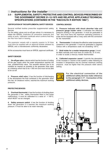
SAFETY DEVICES<br />
1. On-off gas valve: a device which has the function of cutting<br />
off the gas supply when the water temperature reaches the<br />
max. predetermined value. The sensible element has to be<br />
installed as nearest as possible to the generator (flow pipe)<br />
at a distance which has to be < <strong>50</strong>0 mm and must not be able<br />
to be cut-off.<br />
2. Pressure relief valve: it has the function of discharging<br />
in the atmosphere the fluid contained in the generator when<br />
this has, for whatever motive, reached the maximum working<br />
pressure.<br />
PROTECTIVE DEVICES<br />
3. Overheat thermostat: it has the function of shutting down<br />
the generator if the safety thermostat fitted in the boiler<br />
malfunctions. It must be calibrated to a value of < 100°C,<br />
which MUST not be changed.<br />
4. Safety pressure switch: it has the function of shutting<br />
down the generator if it reaches the maximum working<br />
pressure. It must be able to be reset manually.<br />
CONTROL DEVICES<br />
5. Pressure indicator with shock absorber tube and<br />
pressure gauge holder valve: it indicates the effective<br />
pressure existing in the generator. It must be graduated in<br />
“bar” and must have the maximum operating pressure in<br />
scale and be equipped with a 3-way valve with the connection<br />
for the manometer.<br />
6. Thermometer: it indicates the effective water temperature<br />
contained in the generator. It must be graduated in degrees<br />
Celsius with a temperature scale not exceeding 120°C.<br />
7. Bulb holder for a master temperature gauge: it must<br />
be fitted vertically and must have an inside dia. of 10 mm,<br />
in order to locate a mercury master thermometer.<br />
8. Calibrated expansion vessel: it permits the absorption<br />
of the increase in volume of the system’s water following an<br />
increase in temperature and its nominal maximum working<br />
pressure must be higher than the pressure relief valve’s<br />
setting.<br />
6<br />
1<br />
4<br />
6 7<br />
7<br />
3<br />
For the electrical connection of the<br />
additional safety devices make reference<br />
to the paragraph 3.17 - Connection of the<br />
additional safety devices.<br />
5<br />
9<br />
8<br />
2