ALKON 50-70 INST apice a GB.pmd - Unical Lattner Condensing ...
ALKON 50-70 INST apice a GB.pmd - Unical Lattner Condensing ...
ALKON 50-70 INST apice a GB.pmd - Unical Lattner Condensing ...

Create successful ePaper yourself
Turn your PDF publications into a flip-book with our unique Google optimized e-Paper software.
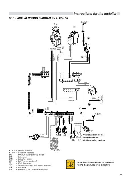
3.18 - ACTUAL WIRING DIAGRAM for <strong>ALKON</strong> <strong>50</strong><br />
DK<br />
E. ACC = Ignition electrode<br />
E. RIV. = Detection electrode<br />
DK = Minimum water pressure switch<br />
SR = CH sensor<br />
SRR = CH return sensor<br />
SS = DHW sensor (optional)<br />
TL = Limit thermostat<br />
TF = Smoke thermostat (only pre-arrangement)<br />
VG = Gas valve<br />
VM = Modulating fan detection/adjustment<br />
BLACK<br />
BROWN<br />
WHITE<br />
NERO<br />
BLU<br />
MA RRONE<br />
ARANCIO<br />
VM<br />
RIL./REG. ALIM.<br />
230V<br />
5 4 2 1<br />
BLACK (-)<br />
BROWN (PWM)<br />
BLUE (TACHO)<br />
ORANGE +<br />
1 2 3<br />
BROWN (L1)<br />
LIGHT-BLUE (N)<br />
GREEN<br />
GREEN<br />
SRR SR<br />
SS<br />
LIGHT-BLUE<br />
BROWN<br />
WHITE<br />
WHITE<br />
LIGHT-BLUE<br />
LIGHT-BLUE<br />
LIGHT-BLUE<br />
BROWN<br />
BROWN<br />
BROWN<br />
LIGHT-BLUE<br />
LIGHT-BLUE<br />
Instructions for the installer<br />
VG<br />
Fs1<br />
LIGHT-BLUE<br />
TL TF<br />
E. ACC<br />
RED<br />
YELL/GREEN<br />
LIGHT-BLUE<br />
BROWN<br />
BLUE<br />
BROWN<br />
WHITE<br />
BROWN<br />
YELL/GREEN<br />
BLACK<br />
BLUE<br />
Note: The pictures shown on the actual<br />
wiring diagram, is purely indicative.<br />
N L1<br />
E. RIV.<br />
230 V - <strong>50</strong> Hz<br />
Prearrangement for the<br />
connection of the<br />
additional safety devices<br />
33