ALKON 50-70 INST apice a GB.pmd - Unical Lattner Condensing ...
ALKON 50-70 INST apice a GB.pmd - Unical Lattner Condensing ...
ALKON 50-70 INST apice a GB.pmd - Unical Lattner Condensing ...

Create successful ePaper yourself
Turn your PDF publications into a flip-book with our unique Google optimized e-Paper software.
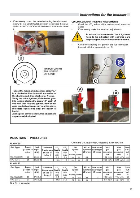
- If necessary correct the value by turning the adjustment<br />
screw “B” in a CLOCKWISE direction to increase the value<br />
and in an ANTICLOCKWISE direction in order to decrease<br />
it.<br />
<strong>ALKON</strong> <strong>50</strong><br />
<strong>ALKON</strong> <strong>70</strong><br />
20<br />
37<br />
FL e FH = parameter<br />
48,5-9,6<br />
48,5-9,6<br />
MINIMUM OUTPUT<br />
ADJUSTMENT<br />
SCREW (B)<br />
Tighten the maximum adjustment screw “A”<br />
in a clockwise direction until you arrive to<br />
the abutting end, than slacken for 7 turns.<br />
Verify the boiler ignition; if the boiler goes<br />
into lockout slacken the screw “A” again of<br />
one turn, than retry the ignition. If the boiler<br />
goes into lockout again, carry out the above<br />
indicated operations until the boiler is<br />
lighted.<br />
At this point carry out the burner adjustment<br />
as previously indicated.<br />
INJECTORS – PRESSURES<br />
Gas Type Supply<br />
pressure<br />
(mbar)<br />
Nat. Gas (G20)<br />
LPG (G31)<br />
Heat<br />
input<br />
(kW)<br />
Collector<br />
Diaphragm<br />
(Ø and n°<br />
holes )<br />
-<br />
-<br />
C02 levels<br />
(%)<br />
min<br />
9,5<br />
11,0<br />
Gas Type Supply<br />
pressure<br />
Heat<br />
input<br />
Collector<br />
Diaphragm<br />
C02 levels<br />
(mbar) (kW) (Ø and n° (%)<br />
holes ) min<br />
Nat. Gas (G20) 20 67,5-9,6 - 9,5<br />
LPG (G31) 37 67,5-9,6 - 11,0<br />
Instructions for the installer<br />
C) COMPLETION OF THE BASIC ADJUSTMENTS<br />
- Check the C0 2 values at the minimum and maximum<br />
outlet<br />
- If necessary make the required adjustments<br />
To ensure correct operation the C0 2 values<br />
have to be adjusted with extreme care<br />
respecting the values indicated in the table.<br />
- Close the sampling test point in the flue inlet/outlet<br />
terminal with the appropriate cap C.<br />
Check the C0 2 levels often, especially at low flow rate<br />
C02 levels<br />
Fan<br />
speed<br />
Mixer Flue outlet<br />
injectors diaphragm<br />
Min.<br />
gas<br />
Max<br />
gas<br />
(%) % (Ø mm) (Ø mm) consumpconsump- max FL (min) FH (max)<br />
tiontion 9,5 26 95 5,6 - 1,02 m³/h 5,13 m³/h<br />
11,0 24 92 5,6 - 0,75 kg/h 3,76 kg/h<br />
Start<br />
output<br />
%<br />
C02 levels<br />
Fan<br />
speed<br />
Mixer Flue outlet<br />
injectors diaphragm<br />
Min.<br />
gas<br />
Max<br />
gas<br />
Start<br />
out-<br />
(%) % (Ø mm) (Ø mm) consumpconsumpput max FL (min) FH (max)<br />
tiontion %<br />
9,5 20 99 9,0 - 1,02 m³/h 7,14 m³/h <strong>50</strong><br />
11,0 20 90 9,0 - 0,75 kg/h 5,24 kg/h 60<br />
40<br />
45<br />
51