The Discontinuous Conduction Mode Sepic and ´ Cuk Power
The Discontinuous Conduction Mode Sepic and ´ Cuk Power
The Discontinuous Conduction Mode Sepic and ´ Cuk Power

You also want an ePaper? Increase the reach of your titles
YUMPU automatically turns print PDFs into web optimized ePapers that Google loves.
SIMONETTI et al.: SEPIC AND ĆUK POWER FACTOR PREREGULATORS 631<br />
(a) (b)<br />
(c) (d)<br />
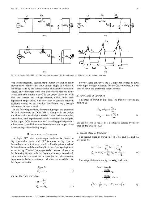
Fig. 3. A <strong>Sepic</strong> DCM–PFP. (a) First stage of operation. (b) Second stage. (c) Third stage. (d) Inductor currents.<br />
loop is not necessary. Second, input–output isolation is easily<br />
implemented. Finally, the input current ripple is defined at<br />
the design stage by the correct choice of magnetic component<br />
values. <strong>The</strong> converters work with zero-current turn-on in the<br />
switch <strong>and</strong> zero-current turn-off in the output diode, but with<br />
high rms current <strong>and</strong> voltage stresses, which limits their<br />
application range. Also, it is necessary to consider inherent<br />
problems caused by an isolation transformer (e.g., leakage<br />
inductance) if one is used.<br />
In the following sections, the operating stages are presented<br />
for both converters as DCM–PFP’s, along with the design<br />
equations <strong>and</strong> a small-signal model. Some design examples,<br />
simulations, <strong>and</strong> experimental results complete the analysis.<br />
In this paper, DCM means that each switching period presents<br />
a time interval in which neither the switch nor the output diode<br />
is conducting (freewheeling stage).<br />
II. ANALYSIS OF OPERATION<br />
A <strong>Sepic</strong> PFP with input–output isolation is shown in<br />
Fig. 1(a), <strong>and</strong> a similar Ćuk PFP is shown in Fig. 1(b). In<br />
the analysis, the output stage is referred to the primary side of<br />
the transformer, <strong>and</strong> the resulting <strong>Sepic</strong> <strong>and</strong> Ćuk topologies are<br />
shown in Fig. 2(a) <strong>and</strong> (b), respectively. Because of space, in<br />
the following figures, only the <strong>Sepic</strong> operation is considered,<br />
but a similar development can be made for the Ćuk converter.<br />
Equations for both converters are identical, provided that, for<br />
the <strong>Sepic</strong> converter,<br />
<strong>and</strong> for the Ćuk converter,<br />
(1)<br />
(2)<br />
For the <strong>Sepic</strong> converter, the capacitor voltage is equal<br />
to the input voltage, whereas, for the Ćuk converter, it is the<br />
sum of input <strong>and</strong> (referred) output voltage.<br />
A. First Stage of Operation<br />
This stage is shown in Fig. 3(a). <strong>The</strong> inductor currents are<br />
defined as<br />
<strong>and</strong> can be seen in Fig. 3(d). This stage is defined by the ON<br />
time of the switch ( ).<br />
B. Second Stage of Operation<br />
<strong>The</strong> second stage is shown in Fig. 3(b), <strong>and</strong> <strong>and</strong><br />
are given by<br />
This stage finishes when <strong>and</strong> lasts<br />
Authorized licensed use limited to: ELETTRONICA E INFORMATICA PADOVA. Downloaded on April 12, 2009 at 16:08 from IEEE Xplore. Restrictions apply.<br />
(3)<br />
(4)<br />
(5)