The Discontinuous Conduction Mode Sepic and ´ Cuk Power
The Discontinuous Conduction Mode Sepic and ´ Cuk Power
The Discontinuous Conduction Mode Sepic and ´ Cuk Power

You also want an ePaper? Increase the reach of your titles
YUMPU automatically turns print PDFs into web optimized ePapers that Google loves.
SIMONETTI et al.: SEPIC AND ĆUK POWER FACTOR PREREGULATORS 633<br />
<strong>The</strong>refore, can be obtained considering the specified<br />
maximum current ripple:<br />
<strong>and</strong><br />
(24)<br />
(25)<br />
( normally is a percentage of the fundamental input current<br />
.)<br />
H. <strong>The</strong> Design of the Intermediate Capacitor<br />
In conventional <strong>Sepic</strong> <strong>and</strong> Ćuk converters, the capacitor<br />
voltage is assumed to be constant. When operating as a PFP,<br />
the capacitor voltage is under the following two conflicting<br />
constraints: 1) to present a nearly constant value within a<br />
switching period <strong>and</strong> 2) to follow the input voltage profile<br />
within a line period. Its value has a significant influence in the<br />
input current waveform. <strong>The</strong> resonant frequency of , ,<br />
<strong>and</strong> must be much greater than the line frequency to avoid<br />
input current oscillations at every line half cycle. Also, the<br />
resonant frequency between <strong>and</strong> must be lower than<br />
the switching frequency to assure almost constant voltage in<br />
a switching period. A good initial approximation for is<br />
given by [9]<br />
where<br />
(26)<br />
(27)<br />
An isolated Ćuk converter presents an additional resonance<br />
caused by the transformer magnetizing inductance that might<br />
constitute a major problem [10]. In the <strong>Sepic</strong> converter, the<br />
magnetizing inductance is usually used as the inductor .<br />
I. Small-Signal <strong>Mode</strong>l<br />
A small-signal model can be easily obtained using the<br />
CIECA approach [11]. <strong>The</strong> following small-signal perturbations<br />
will be applied to both input <strong>and</strong> output average currents:<br />
where the caret means steady-state value <strong>and</strong> means<br />
the introduced perturbation (small-signal value). Applying<br />
the perturbations in (10) <strong>and</strong> performing the small-signal<br />
approximation ( ) results in<br />
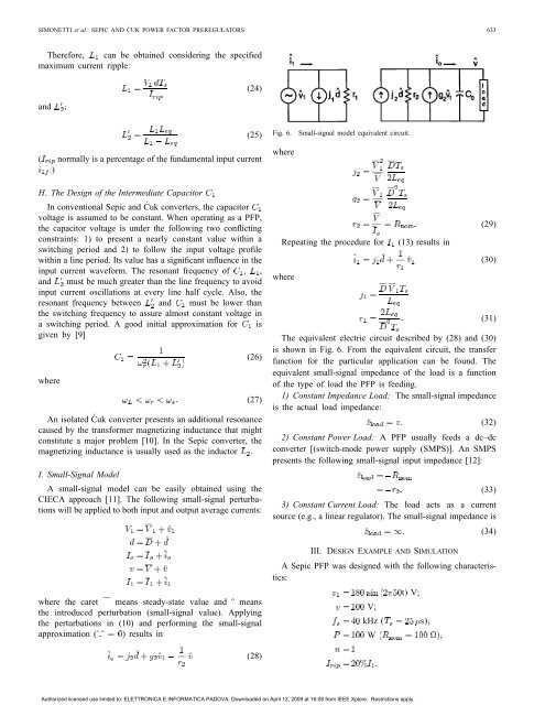
(28)<br />
Fig. 6. Small-signal model equivalent circuit.<br />
where<br />
Repeating the procedure for (13) results in<br />
where<br />
(29)<br />
(30)<br />
(31)<br />
<strong>The</strong> equivalent electric circuit described by (28) <strong>and</strong> (30)<br />
is shown in Fig. 6. From the equivalent circuit, the transfer<br />
function for the particular application can be found. <strong>The</strong><br />
equivalent small-signal impedance of the load is a function<br />
of the type of load the PFP is feeding.<br />
1) Constant Impedance Load: <strong>The</strong> small-signal impedance<br />
is the actual load impedance:<br />
(32)<br />
2) Constant <strong>Power</strong> Load: A PFP usually feeds a dc–dc<br />
converter [(switch-mode power supply (SMPS)]. An SMPS<br />
presents the following small-signal input impedance [12]:<br />
(33)<br />
3) Constant Current Load: <strong>The</strong> load acts as a current<br />
source (e.g., a linear regulator). <strong>The</strong> small-signal impedance is<br />
(34)<br />
III. DESIGN EXAMPLE AND SIMULATION<br />
A <strong>Sepic</strong> PFP was designed with the following characteristics:<br />
t V;<br />
V;<br />
kHz s<br />
W<br />
Authorized licensed use limited to: ELETTRONICA E INFORMATICA PADOVA. Downloaded on April 12, 2009 at 16:08 from IEEE Xplore. Restrictions apply.